

Page 1

AC1200 Smart Dual-band WiFi Router
Model: AC5
User Guide
Page 2

Copyright Statement
All rights reserved © 2017 Shenzhen Tenda Technology Co., Ltd.
No part of this publication can be reproduced, transcribed, transmitted, or translated into any language in any
form or by any means without the prior written permission of Shenzhen Tenda Technology Co., Ltd.
is a registered trademark legally held by Shenzhen Tenda Technology Co., Ltd. Other brand and
product names mentioned herein are trademarks or registered trademarks of their respective holders.
This document will be updated aperiodically for version upgrade or other reasons. Unless otherwise provided, all
information herein is for references only, which do not constitute a warranty of any kind, express or implied.
This guide provides detailed descriptions about how to use AC5 and set its functions, without attention to
onscreen instructions or simple information review.
Page 3

Item
Presentation
Example
Menu
Bold
Click menu Start.
Button
Bold
Click OK.
Cascading menus
>
Click System Settings > Time Settings.
Parameter and value
Bold
Set User Name to Tom.
Symbol
Meaning
This format is used to highlight information of importance or special interest. Ignoring
this type of note may result in ineffective configurations, loss of data or damage to
device.
This format is used to highlight a procedure that will save time or resources.
Acronym or
Abbreviation
Full Spelling
ISP
Internet Service Provider
DNS
Domain Name System
SSID
Service Set Identifier
DHCP
Dynamic Host Configuration Protocol
VPN
Virtual Private Network
L2TP
Layer 2 Tunneling Protocol
Preface
Thank you for choosing Tenda! Please read this user guide before you start with AC5.
Conventions
Pictures, IP addresses and other data herein are for references only. Specific requests are subject to actual
situations.
The formats that may be found in this document are defined as follows.
The symbols that may be found in this document are defined as follows.
Acronyms and Abbreviations
Page 4

Acronym or
Abbreviation
Full Spelling
MPPE
Microsoft Point-to-Point Encryption
PPP
Point To Point Protocol
PPTP
Point to Point Tunneling Protocol
IPTV
Internet Protocol Television
DDNS
Dynamic Domain Name System
DMZ
Demilitarized Zone
Hotline
Global: (86) 755-27657180
Email
support@tenda.com.cn
United States: 1-800-570-5892
Canada: 1-888-998-8966
Hong Kong: 00852-81931998
Australia: 1300787922
New Zealand: 800787922
Website
http://www.tendacn.com
Skype
tendasz
Additional Information
For more information, please go to Tenda website http://www.tendacn.com.
Technical Support
For more help, contact us by any of the following means. We will be glad to assist you as soon as possible.
Page 5

Contents
Introduction ......................................................................................................................................................... 6 1
1.1 Overview ........................................................................................................................................................ 6
1.2 Features ......................................................................................................................................................... 6
1.3 Appearance .................................................................................................................................................... 7
1.3.1 Front Panel .......................................................................................................................................... 7
1.3.2 Rear Panel ........................................................................................................................................... 8
1.3.3 Label at the Bottom ............................................................................................................................ 9
Quick Setup for the Internet .............................................................................................................................. 10 2
2.1 Setting the New Router to Access the Internet ........................................................................................... 10
2.1.1 Example: Smart Phone ...................................................................................................................... 10
2.1.2 Example: Computer .......................................................................................................................... 16
2.2 Renewing the Original Router by AC5 ......................................................................................................... 19
2.2.1 Example: Smart Phone ...................................................................................................................... 19
2.2.2 Example: Computer .......................................................................................................................... 26
Web UI Description ............................................................................................................................................ 30 3
3.1 Log in to the Web UI of the Router .............................................................................................................. 30
3.2 Logging out of the Web UI of the Router .................................................................................................... 31
Internet Status ................................................................................................................................................... 32 4
4.1 Viewing Network Status .............................................................................................................................. 32
4.2 Viewing Online Devices ............................................................................................................................... 33
4.2.1 Adding to Blacklist ............................................................................................................................ 34
4.2.2 Removing from Blacklist ................................................................................................................... 34
4.3 Viewing WiFi Information ............................................................................................................................ 34
4.4 Viewing Other Status Information ............................................................................................................... 36
Internet Settings ................................................................................................................................................ 37 5
5.1 Overview ...................................................................................................................................................... 37
5.2 Setting Up an Internet Connection with PPPoE ........................................................................................... 39
5.3 Setting Up an Internet Connection with a Dynamic IP Address .................................................................. 41
5.4 Setting Up an Internet Connection with a Static IP Address ....................................................................... 42
1
Page 6

WiFi Settings ...................................................................................................................................................... 44 6
6.1 WiFi Name & Password ............................................................................................................................... 44
6.1.1 Overview ........................................................................................................................................... 44
6.1.2 Modifying WiFi Name and Password ................................................................................................ 45
6.2 WiFi Schedule .............................................................................................................................................. 47
6.2.1 Overview ........................................................................................................................................... 47
6.2.2 Example............................................................................................................................................. 48
6.3 Wireless Repeating ...................................................................................................................................... 49
6.3.1 Overview ........................................................................................................................................... 49
6.3.2 Example............................................................................................................................................. 50
6.4 Channel & Bandwidth .................................................................................................................................. 53
6.4.1 Overview ........................................................................................................................................... 53
6.4.2 Changing Channel ............................................................................................................................. 55
6.5 WPS.............................................................................................................................................................. 56
6.5.1 Overview ........................................................................................................................................... 56
6.5.2 Connecting Devices to the WiFi ........................................................................................................ 57
6.5.3 Example............................................................................................................................................. 61
6.6 Beamforming+ ............................................................................................................................................. 64
6.6.1 Overview ........................................................................................................................................... 64
6.6.2 Setting Beamforming+ ...................................................................................................................... 65
6.7 AP Mode ...................................................................................................................................................... 65
6.7.1 Overview ........................................................................................................................................... 65
6.7.2 Enabling AP Mode ............................................................................................................................. 66
6.7.3 Example............................................................................................................................................. 67
6.8 Anti-interference ......................................................................................................................................... 68
Guest Network ................................................................................................................................................... 70 7
7.1 Overview ...................................................................................................................................................... 70
7.2 Setting Guest Network................................................................................................................................. 71
Parental Control ................................................................................................................................................. 72 8
8.1 Overview ...................................................................................................................................................... 72
8.2 Setting a Parental Control Rule .................................................................................................................... 72
8.2.1 Scenario 1: The Device Has Connected to the Router ...................................................................... 72
2
Page 7

8.2.2 Scenario 2: The Device has not Connected to the Router ................................................................ 73
8.3 Example ....................................................................................................................................................... 75
VPN .................................................................................................................................................................... 77 9
9.1 PPTP Server .................................................................................................................................................. 77
9.1.1 Overview ........................................................................................................................................... 77
9.1.2 Example............................................................................................................................................. 79
9.2 Online PPTP Users ....................................................................................................................................... 84
9.3 PPTP/L2TP Client .......................................................................................................................................... 85
9.3.1 Overview ........................................................................................................................................... 85
9.3.2 Example............................................................................................................................................. 86
Advanced Settings ............................................................................................................................................. 88 10
10.1 Bandwidth Control .................................................................................................................................... 88
10.1.1 Overview ......................................................................................................................................... 88
10.1.2 Example .......................................................................................................................................... 89
10.2 Tenda App .................................................................................................................................................. 90
10.2.1 Example .......................................................................................................................................... 90
10.3 Sleeping Mode ........................................................................................................................................... 94
10.4 LED Control ................................................................................................................................................ 95
10.5 Filter MAC Address .................................................................................................................................... 96
10.5.1 Overview ......................................................................................................................................... 96
10.5.2 Adding a MAC Address Filter Rule .................................................................................................. 97
10.5.3 Deleting a MAC Address Filter Rule ................................................................................................ 97
10.5.4 Example .......................................................................................................................................... 98
10.6 Firewall .................................................................................................................................................... 100
10.7 IPTV.......................................................................................................................................................... 101
10.7.1 Overview ....................................................................................................................................... 101
10.7.2 Example ........................................................................................................................................ 102
10.8 Static Route ............................................................................................................................................. 103
10.8.1 Overview ....................................................................................................................................... 103
10.8.2 Example ........................................................................................................................................ 104
10.9 DDNS ....................................................................................................................................................... 107
10.9.1 Overview ....................................................................................................................................... 107
3
Page 8

10.9.2 Adding a DDNS Rule ...................................................................................................................... 108
10.9.3 Example ........................................................................................................................................ 110
10.10 Virtual Server ........................................................................................................................................ 113
10.10.1 Adding a Virtual Server Rule ....................................................................................................... 114
10.10.2 Deleting a Virtual Server Rule ..................................................................................................... 115
10.10.3 Example ...................................................................................................................................... 115
10.11 DMZ Host............................................................................................................................................... 118
10.12 UPnP ...................................................................................................................................................... 119
System Settings ............................................................................................................................................... 120 11
11.1 LAN Settings ............................................................................................................................................ 120
11.1.1 Overview ....................................................................................................................................... 120
11.1.2 Modifying the LAN IP Address ...................................................................................................... 121
11.2 DHCP Reservation .................................................................................................................................... 122
11.2.1 Adding a DHCP Reservation Rule .................................................................................................. 123
11.2.2 Deleting a DHCP Reservation Rule ................................................................................................ 124
11.3 WAN Settings ........................................................................................................................................... 124
11.3.1 Overview ....................................................................................................................................... 124
11.3.2 Modifying MTU Value ................................................................................................................... 125
11.3.3 Changing the MAC Address of the WAN Port ............................................................................... 125
11.4 Time Settings ........................................................................................................................................... 126
11.5 Login Password ........................................................................................................................................ 127
11.5.1 Overview ....................................................................................................................................... 127
11.5.2 Changing the Login Password ....................................................................................................... 127
11.6 Reboot and Reset .................................................................................................................................... 128
11.6.1 Overview ....................................................................................................................................... 128
11.6.2 Rebooting the Router ................................................................................................................... 129
11.6.3 Resetting the Router ..................................................................................................................... 129
11.7 Firmware Upgrade ................................................................................................................................... 129
11.7.1 Overview ....................................................................................................................................... 129
11.7.2 Steps for Local Upgrade ................................................................................................................ 130
11.7.3 Steps for Online Upgrade .............................................................................................................. 131
11.8 Backup/Restore ....................................................................................................................................... 132
4
Page 9

11.8.1 Overview ....................................................................................................................................... 132
11.8.2 Steps for Back Up .......................................................................................................................... 132
11.8.3 Steps for Restoring the Configuration ........................................................................................... 132
11.9 Remote Management .............................................................................................................................. 133
11.9.1 Overview ....................................................................................................................................... 133
11.9.2 Configuring Remote Management ............................................................................................... 134
11.9.3 Example ........................................................................................................................................ 134
11.10 System Status ........................................................................................................................................ 136
11.10.1 Information ................................................................................................................................. 136
11.10.2 WAN Status ................................................................................................................................. 137
11.10.3 LAN Status ................................................................................................................................... 138
11.10.4 WiFi Status .................................................................................................................................. 138
11.11 System Log............................................................................................................................................. 139
11.12 Automatic Maintenance ........................................................................................................................ 140
11.12.1 Overview ..................................................................................................................................... 140
11.12.2 Configuring System Reboot Schedule ......................................................................................... 141
5
Page 10

1
Introduction
1.1 Overview
Tenda AC5 is a dual-band WiFi router dedicated to fiber users with small and medium apartments. Adopting
brand new 11AC Wave2.0 technology, four 5dBi high-gain external antennas, AC5 offers simultaneous dual-band
WiFi speed as high as 1167 Mbps. With Beamforming+ technology, AC5 features robust wall penetration capacity,
creating faster and better network for users.
1.2 Features
Support 802.11ac wave2 standard.
Support 4 megabit auto-negotiation ports.
With 4 omni external antennas.
Support the WiFi Schedule function. Users can set the WiFi off in specified period.
Support enabling/disabling the router by clicking WiFi on/off button on the rear panel of the router.
Support 9 V, 1 A power input.
With wireless transmission speed as high as 1167 Mbps.
Support the Wireless Repeating, and Bandwidth Control functions.
Support immigration of ISP username and password, helping users complete internet settings quickly.
Support remote management using Tenda APP.
6
Page 11
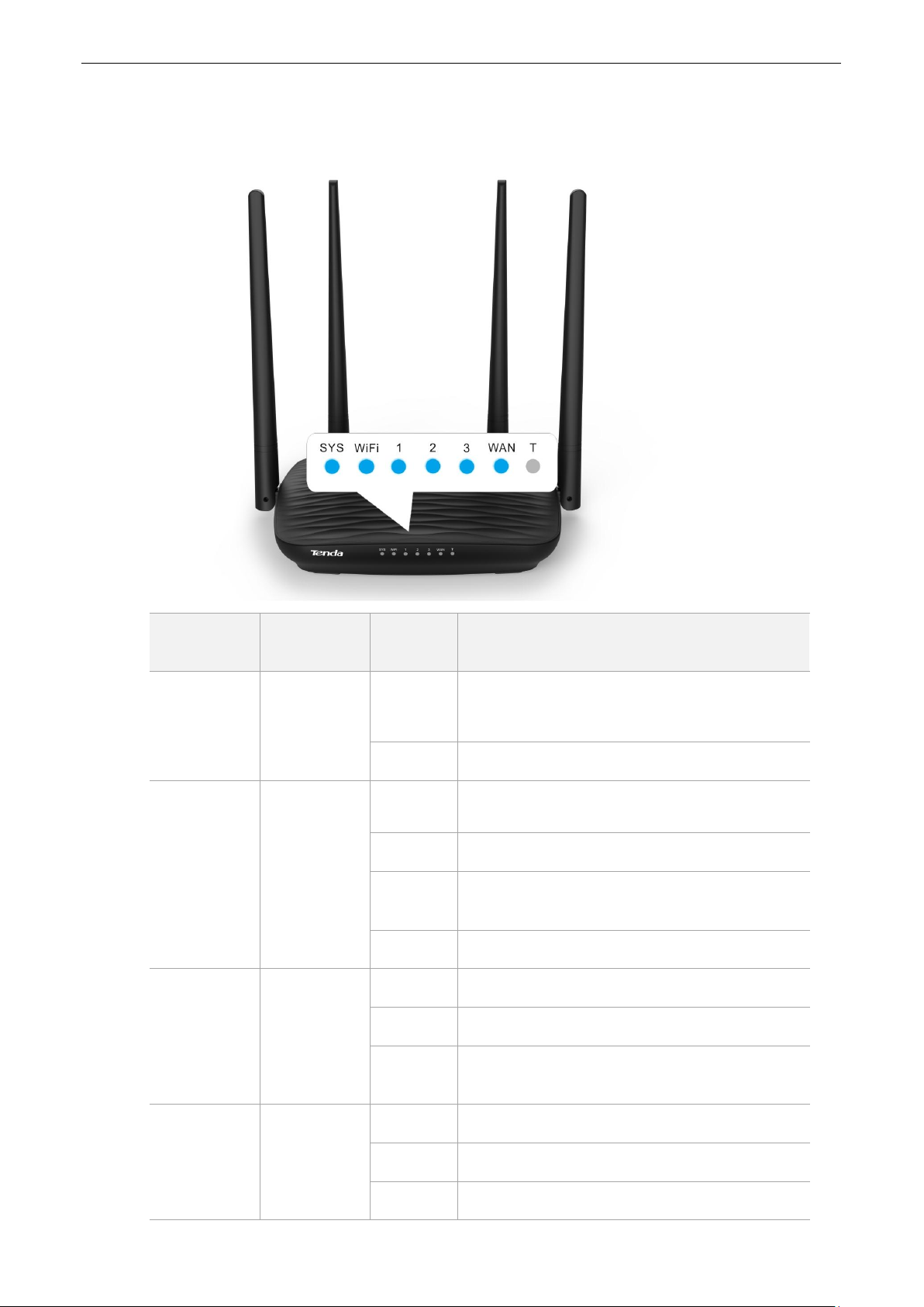
1.3 Appearance
LED Indicator
LED Indicator
Name
Status
Description
SYS
System
indicator
Solid on
The router is starting.
The system is faulty after startup.
Blinking
The system is working properly.
WIFI
WiFi/WPS
indicator
Solid on
At least the 2.4 GHz or 5 GHz WiFi network is
enabled.
Blinking
Data is transmitting wirelessly.
Slow
blinking
The router is performing WPS negotiation.
Off
The wireless function is disabled.
1/2/3
LAN port
indicator
Solid on
The LAN port is connected properly.
Blinking
Data is transmitting over the LAN port.
Off
The LAN port is unconnected or connected
improperly.
WAN
WAN port
indicator
Solid on
The WAN port is connected properly.
Blinking
Data is transmitting over the WAN port.
Off
The WAN port is unconnected or connected
1.3.1 Front Panel
7
Page 12
LED Indicator
LED Indicator
Name
Status
Description
improperly.
T
Reserved
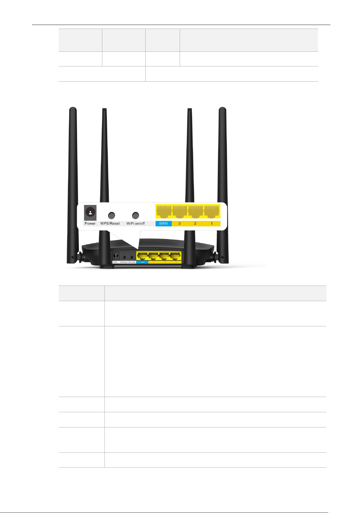
1.3.2 Rear Panel
Port/Button
Description
Power
Used to power on/off the router using the power adapter included with the
package.
WPS/Reset
Used to start the WPS negotiation process of the router, or to restore the router to
the factory settings.
WPS: Press the button of the router. Then enable the WPS function of
another device within 2 minutes to establish a WPS connection.
Reset: Hold the button down for 8 seconds, and wait until all LED indicators
blink once to restore the factory settings of the router.
WiFi on/off
You can enable/disable WiFi of the router by clicking this button.
WAN
Used to connect this router to the internet.
3
By default, it functions as a LAN port. But after the IPTV function of the router is
enabled, it functions only as an IPTV port used to connect to a set-top box.
2/1
Used to connect to devices such as computers and switches.
8
Page 13
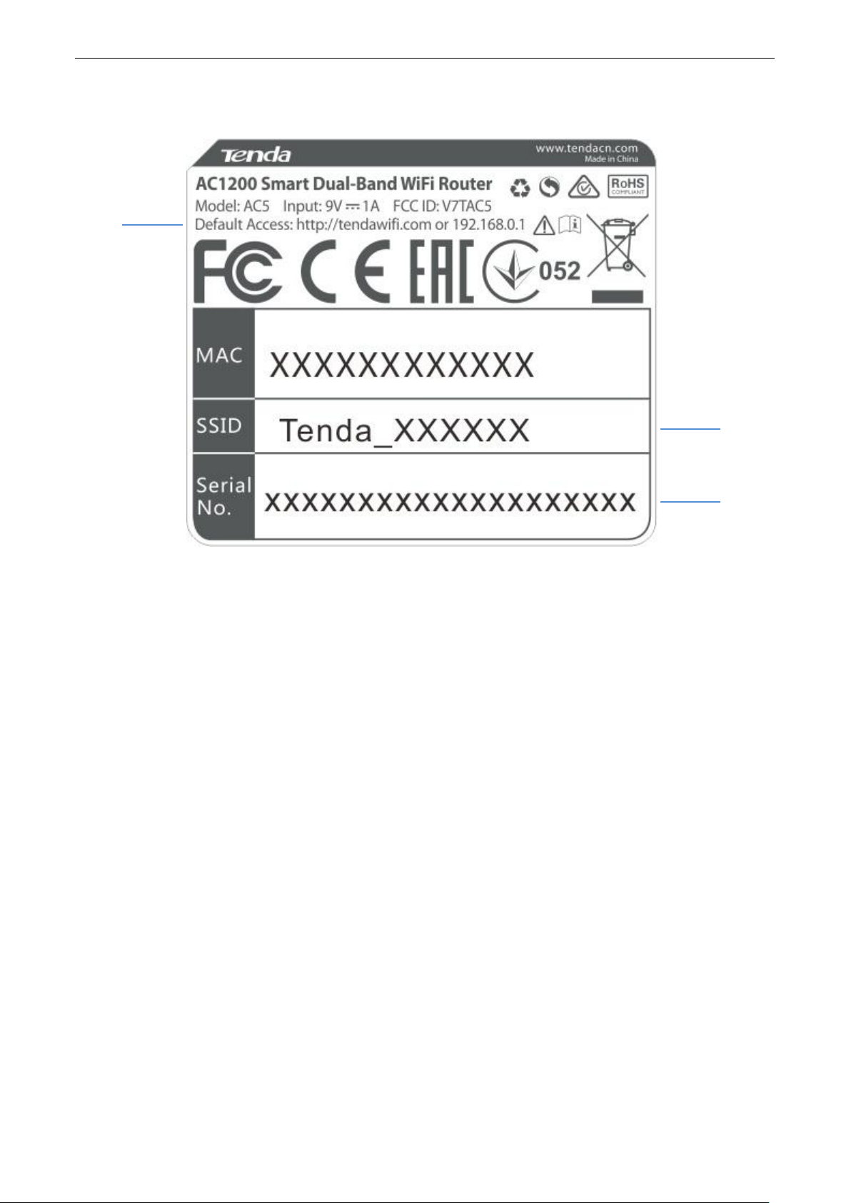
1.3.3 Label at the Bottom
(1)
(2)
(3)
The label shows the SSID, and login IP address of the router. Read for reference if needed.
(1): Login IP address of the router. You can use this IP address to access the web UI of the router.
(2): Default WiFi name of the router.
When you use the router for the first time, search and connect wireless devices (such as smart
phones) to this SSID to log in to the web UI of the router for internet settings.
After the router is connected to the internet, if this SSID is unchanged, wireless devices (such as
smart phones) can search and connect to this SSID to access the internet.
(3): Serial number of the router. If the router is faulty, you need to provide this serial number when sending the
router for repair.
9
Page 14

2
Quick Setup for the
Internet
2.1 Setting the New Router to Access the Internet
2.1.1 Example: Smart Phone
Step 1 Connect devices.
(1) Power on the new router AC5 using the power adapter included with the package.
(2) Plug the Ethernet cable that has connected to the internet into the WAN port of the router.
(3) Connect your smart phone to the SSID shown on the bottom label. By default, this wireless
network has no WiFi password.
10
Page 15
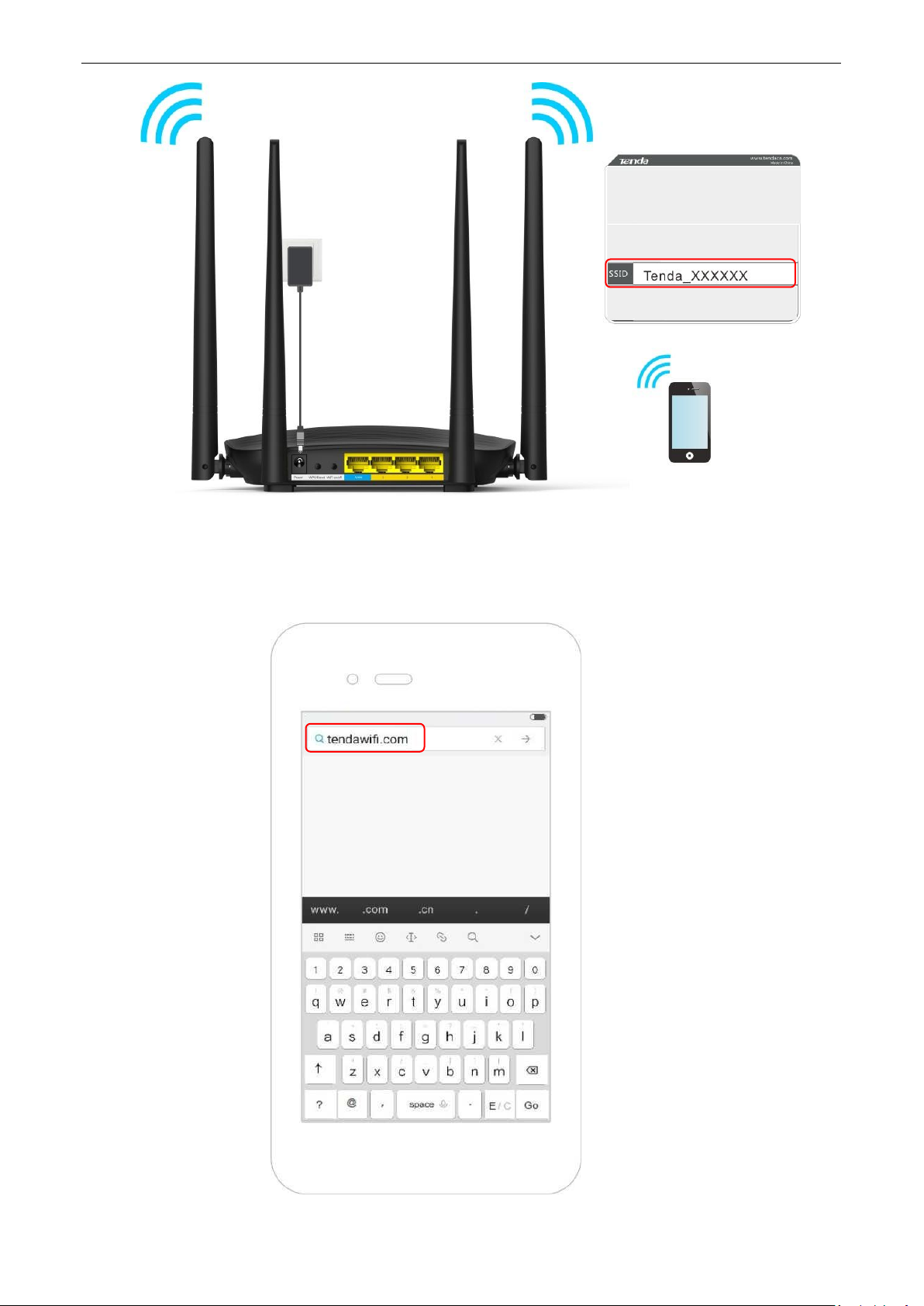
Step 2 Log in to the web UI of the router for internet setup.
(1) Start a web browser on the phone that has connected to the router’s WiFi, and enter
tendawifi.com or 192.168.0.1.
(2) Tap on the Search symbol.
11
Page 16

(3) Tap on Start.
12
Page 17
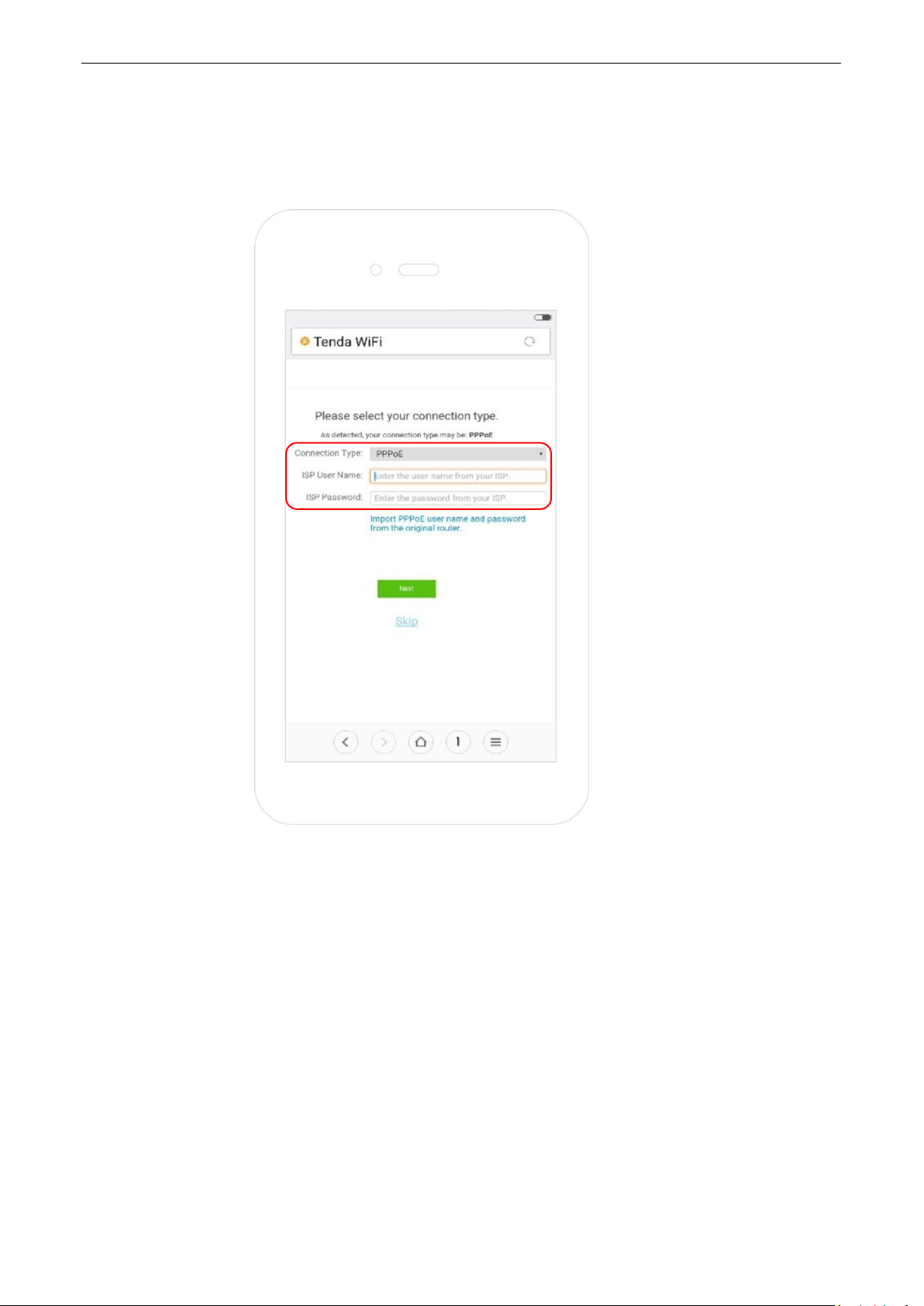
(4) System detects your connection type automatically. Complete your setup according to the
onscreen instructions. (Taking PPPoE as an example in the following procedures)
(5) ISP User Name: Enter the user name provided by your ISP.
(6) ISP Password: Enter the password provided by your ISP.
(7) Tap on Next.
13
Page 18
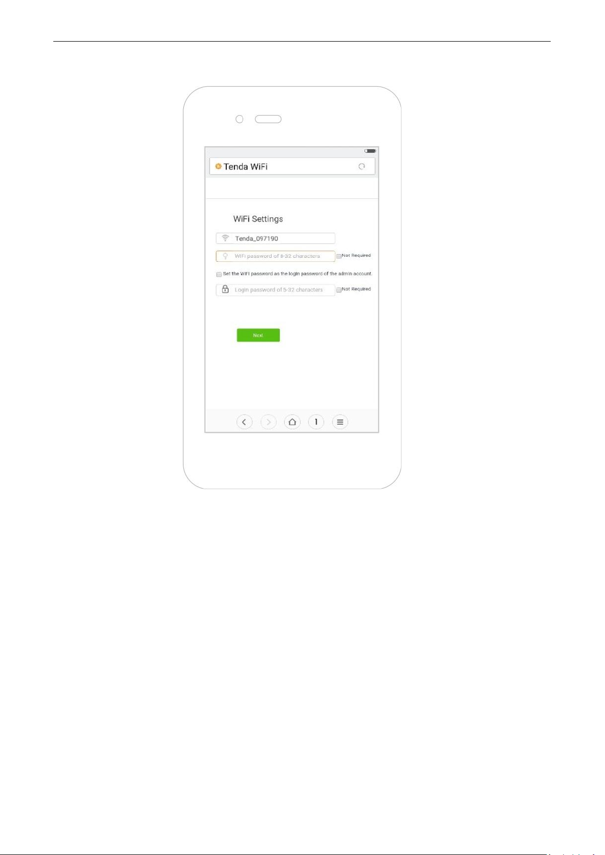
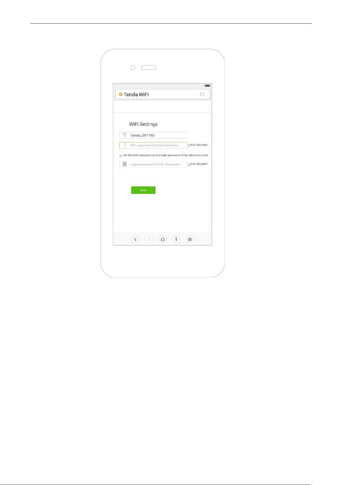
(8) Set WiFi name, WiFi password, and login password.
(9) Tap on Next.
14
Page 19

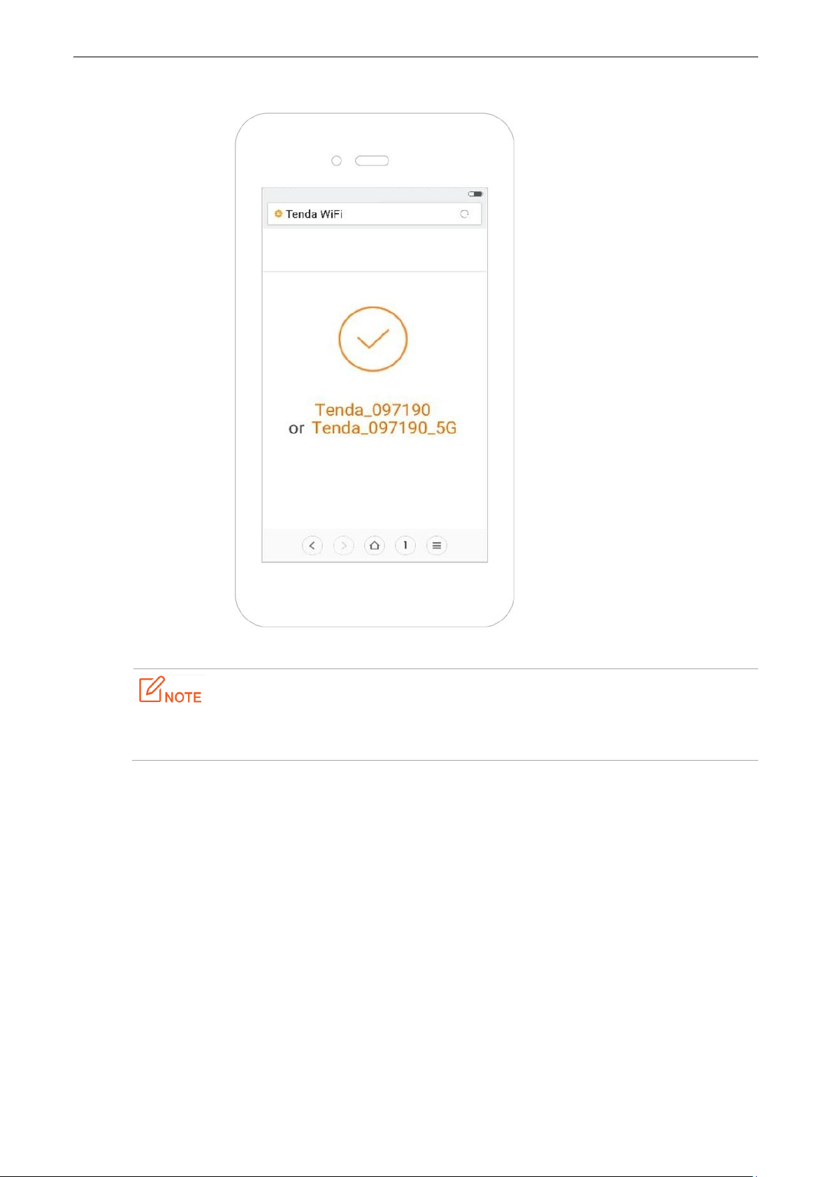
(10) Wait a moment until the router accesses the internet successfully. Wireless devices, such as
phones, need to connect to the WiFi again to access the internet.
—End
If the WiFi name and the WiFi password have been changed, connect your devices to the wireless
network of the router again using the new WiFi name and WiFi password.
For more product and function details, refer to relevant contents in this user guide.
15
Page 20

2.1.2 Example: Computer
Step 1 Connect devices.
(1) Power on the router using the power adapter included with the package.
(2) Plug the Ethernet cable that has connected to the internet into the WAN port of the router.
(3) Connect your computer to a LAN port (1/2/3) of the router using an Ethernet cable.
If a desktop computer is used to connect to the router’s WiFi network, you need to install a wireless
adapter on it first.
16
Page 21
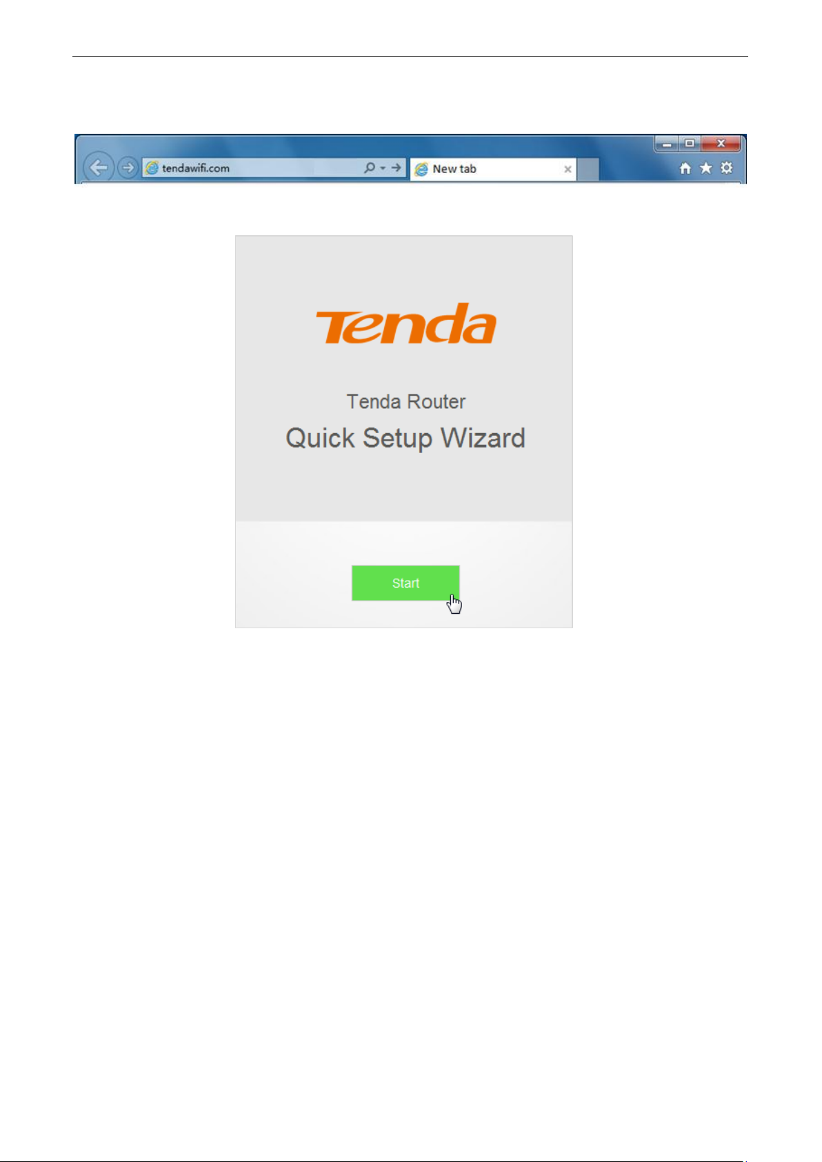
Step 2 Log in to the web UI of the router for internet setup.
(1) Start a web browser on the computer that has connected to the router. Enter tendawifi.com or
192.168.0.1, and press Enter.
(2) Click Start.
17
Page 22

(3) System detects your connection type automatically. Complete your setup according to the
onscreen instructions. (Taking PPPoE as an example in the following procedures)
(4) ISP User Name: Enter the user name provided by your ISP.
(5) ISP Password: Enter the password provided by your ISP.
(6) Click Next.
(7) Set WiFi name, WiFi password, and login password.
(8) Click Next.
18
Page 23

(9) Connected. If you want to configure more functions of the router, click More.
—End
If your desktop connects to the router’s WiFi network, and the WiFi name and the WiFi password have
been changed, connect the desktop to the WiFi network of the router again using the new WiFi name
and WiFi password.
2.2 Renewing the Original Router by AC5
This setup method applies to users who renew their original routers using AC5 for the internet and their
connection types are PPPoE. The method supports migration of ISP user name and password from the original
router to AC5 quickly.
2.2.1 Example: Smart Phone
Step 1 Connect devices.
(1) Power on the original router and AC5.
(2) Connect the WAN port of the original router to a LAN port (1/2/3) of AC5 using an Ethernet cable.
When the LAN and WAN indicators of the new router are solid on for 3 seconds after fast blinking,
the ISP user name and password of the original router are migrated to the new router
successfully.
(3) Remove the original router.
19
Page 24

(4) After successful migration, plug the Ethernet cable that has connected to the internet into the
WAN port of AC5.
(5) Connect wireless clients such as phones to the WiFi of AC5. By default, this WiFi has no password.
20
Page 25

Step 2 Log in to the web UI of the router for internet setup.
(1) Start a web browser on the phone that has connected to the router’s WiFi. Enter tendawifi.com
or 192.168.0.1.
(2) Tap on the Search symbol.
21
Page 26

(3) Tap on Start.
22
Page 27
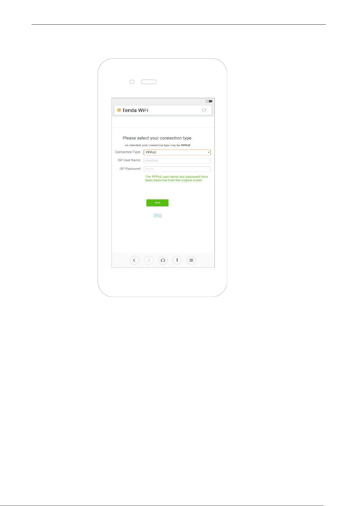
(4) The system enters the ISP user name and ISP password on this page automatically. Assume that
the user name in this example is chenhao, and password is 1234567.
(5) Tap on Next.
23
Page 28
(6) Set WiFi name, WiFi password, and login password.
(7) Tap on Next.
24
Page 29
(8) Wait a second until the router accesses the internet successfully. Wireless devices, such as phones,
need to connect to the WiFi of the router again to access the internet.
—End
If the WiFi name and the WiFi password have been changed, connect your devices to the WiFi network
of the router again using the new WiFi name and WiFi password.
25
Page 30
2.2.2 Example: Computer
Step 1 Connect devices.
(1) Power on the original router and AC5.
(2) Connect the WAN port of the original router to a LAN port (1/2/3) of AC5 using an Ethernet cable.
When the LAN and WAN indicators of the new router are solid on for 3 seconds after fast blinking,
the ISP user name and password of the original router are migrated to the new router
successfully.
(3) Remove the original router.
(4) After successful migration, plug the Ethernet cable that has connected to the internet into the
WAN port of AC5.
(5) Connect your computer to a LAN port (1/2/3) of the router using an Ethernet cable.
If a desktop is used to connect to the router’s WiFi network, you need to install a wireless adapter on it
first.
26
Page 31

Step 2 Log in to the web UI of the router for internet setup.
(1) Start a web browser on the computer that has connected to the router. Enter tendawifi.com or
192.168.0.1, and press Enter.
(2) Click Start.
27
Page 32

(3) The system enters the ISP user name and ISP password on this page automatically. Assume that
the user name in this example is chenhao, and password is 1234567.
(4) Click Next.
28
Page 33

(5) Set WiFi name, WiFi password, and login password.
(6) Click Next.
(7) Connected. If you want to configure more functions of the router, click More.
—End
If your desktop connects to the router’ WiFi network, and the WiFi name and the WiFi password have
been changed, connect the computer to the WiFi of the router again using the new WiFi name and WiFi
password.
29
Page 34

3
Web UI Description
3.1 Log in to the Web UI of the Router
If you use the router for the first time, refer to Chapter 2 Quick Setup for the internet for login method. To log
in to the web UI of the router after quick setup, refer to the following sections.
1. Start a web browser on the device that has connected to the router. Enter tendawifi.com or
192.168.0.1, and press Enter.
2. Enter your login password. Click Login.
—End
If the figure does not appear, set the local area connection of your computer to Obtain an IP address
automatically and Obtain DNS server address automatically. Then try to log in again. For steps to set the local
area connection of your computer, refer to A1 Setting the IP Address of Your Computer in appendixes.
30
Page 35

Log in to the web UI of the router successfully.
3.2 Logging out of the Web UI of the Router
If you log in to the web UI of the router and perform no operation within 5 minutes, the router logs you out. In
addition, clicking Exit on the upper right corner of the web UI can log out as well.
31
Page 36

Parameter
Description
Current Speed
It specifies the download and upload speed of the router’s WAN port.
WAN IP Address
It specifies the IP address of the router’s WAN port.
Firmware Version
It specifies the current firmware version of the router. After performing firmware
upgrade based on the procedures in 11.7 Firmware Upgrade, you can check
whether the upgrade succeeds here.
4
This module enables you to view the network status of the router, online devices, WiFi information and other
status information.
Internet Status
4.1 Viewing Network Status
The Internet Status page shows the current network status of the router.
When the internet icon is displayed, the router is connected to the internet successfully and devices can
access the internet through the router.
Parameter descriptions
32
Page 37

When Connection failed is displayed, click Connection failed for Internet Settings page. Follow the
onscreen instructions to resolve the issue.
4.2 Viewing Online Devices
On the right part of the Internet status page, you can view the number of online devices and get to know
about WiFi extender.
33
Page 38

Clicking Online enables you to view detailed information about the connected devices. See the following figure.
4.2.1 Adding to Blacklist
When detecting an unknown device in Attached Devices, you can click Add to Blacklist to add it to blacklist.
Devices in blacklist cannot access the internet through the router.
4.2.2 Removing from Blacklist
To remove a device from the blacklist, choose Internet Status > Online to open the Manage Device page.
Locate the device you want to remove from the blacklist, and click Remove. Devices removed from the blacklist
can access the internet through the router again.
4.3 Viewing WiFi Information
The upper-right of the Internet Status page shows the WiFi names at the 2.4 GHz/5 GHz networks. After the
router has connected to the internet, wireless devices, such as smart phones, can access the internet by
connecting to the wireless networks.
34
Page 39
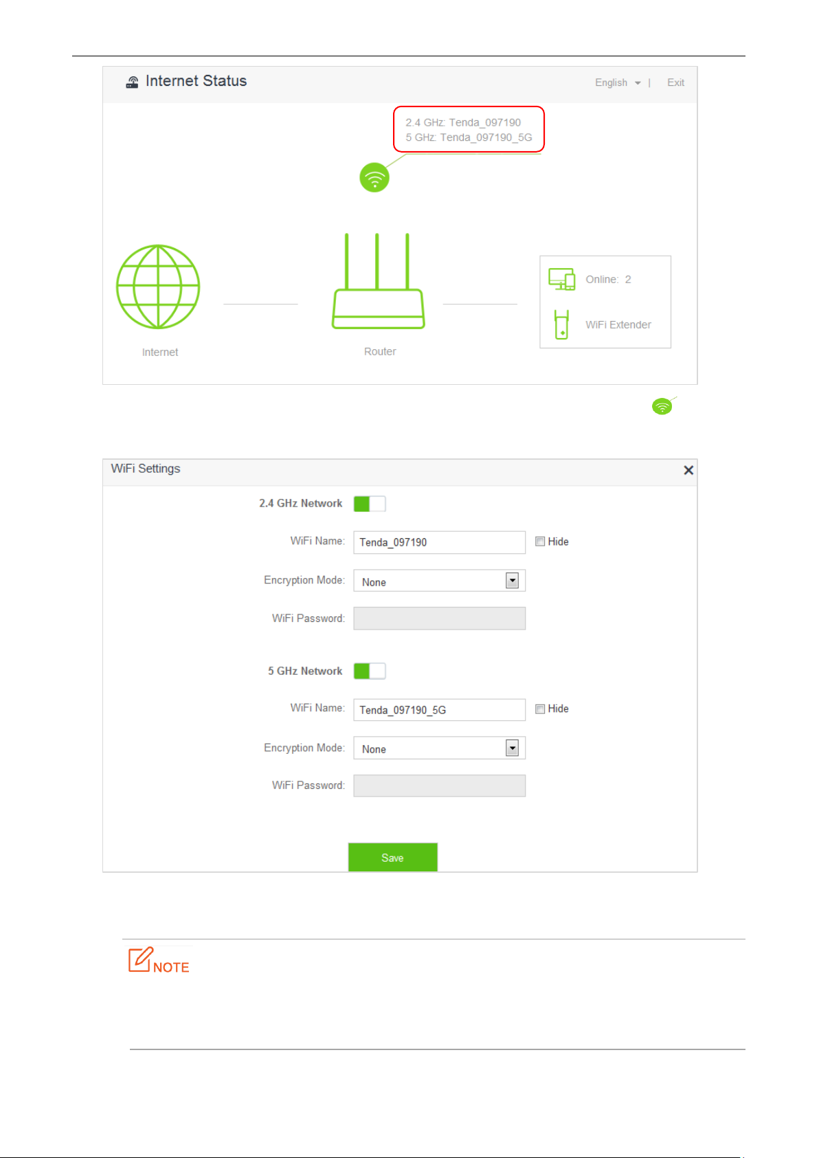
To change the WiFi name or WiFi password at 2.4 GHz/5 GHz network, click Internet Status > to access
the WiFi Settings page. See the figure below.
Set the parameters as required and click Save. For detailed instructions, refer to WiFi Name & Password in
Chapter 6 WiFi Settings.
Only devices compatible with 5 GHz signal can search and connect to the 5 GHz signal.For security of
your wireless network, you are strongly recommend to select a encryption mode and set a WiFi
password for your router.
35
Page 40

4.4 Viewing Other Status Information
Clicking enables you to view the system status, including basic information, WAN status, LAN status and
WiFi status of the router. For detailed parameter descriptions, refer to 11 System Settings.
36
Page 41

Internet
Connection
Type
Description
PPPoE
ISP provides a user name and a password.
Dynamic IP
Address
ISP provides no user name, password, or any information about IP address.
Static IP
Address
ISP provides IP address, subnet mask, default gateway, primary DNS server. And the
secondary DNS server is optional.
5
Internet Settings
5.1 Overview
This module enables you to set internet parameters.Usually, when you use the router for the first time or after
you reset the router, the router detects your internet connection type automatically. You are recommended to
select the detected type and follow the Quick Setup Wizard instructions to configure internet settings.
If you need to change the internet parameters, you can configure them on the Internet Settings page.
The following table may help you understand your internet connection type. If you are still uncertain about
your internet connection type, consult your ISP.
37
Page 42

To access the Internet Settings page, click Internet Settings. PPPoE is taken as an example here for better
guidance. Assume that the ISP user name in this example is chenhao, and password is 1234567. The following
page appears after you finish the configuration.
38
Page 43

Parameters descriptions
Parameter
Description
WAN Port
The current status of the WAN port, including Ethernet cable connected and
Ethernet cable disconnected.
Connection Type
It specifies how the router is connected to internet. This router supports three
connection types. They are PPPoE, Dynamic IP Address, and Static IP Address.
Please select one according to your need.
ISP User Name
Enter the user name provided by your ISP.
ISP Password
Enter the password provided by your ISP.
DNS Settings
It specifies how the router obtains DNS information. This item is only needed
when you choose to connect the internet by PPPoE or Dynamic IP Address.
Automatic: The router obtains DNS information from superior device
automatically.
Manual: You need to enter correct DNS information manually.
IP Address
The information is needed only when you choose to connect the internet by Static
IP Address. You need to enter the IP address and other information provided by
your ISP.
Subnet Mask
Default Gateway
Primary DNS
Server
Secondary DNS
Server
Connection Status
It specifies whether the router is connected to the internet. If the Connected. You
can access the internet now. message appears after a while, the router is
connected to the internet successfully and you can access the internet through
your router.
When other messages appear, the router fails to connect the internet. Please
perform according to onscreen instructions.
Connected
Duration
It specifies how long the router is connected to the internet successfully this time.
5.2 Setting Up an Internet Connection with PPPoE
Procedures:
1. To access the configuration page, click Internet Settings.
2. Connection Type: Choose PPPoE.
39
Page 44

3. ISP User Name: Enter the user name provided by your ISP.
4. ISP Password: Enter the password provided by your ISP.
5. Click Connect.
—End
Verification
Assume that the ISP user name is chenhao, and password is 1234567. If the Connected. You can access the
internet now. message appears after a while, you can access the internet through the router in a wired or
wireless manner.
40
Page 45

5.3 Setting Up an Internet Connection with a
Dynamic IP Address
Procedures:
1. To access the configuration page, click Internet Settings.
2. Connection Type: Choose Dynamic IP Address.
3. Click Connect.
—End
Verification
If the Connected. You can access the internet now. message appears after a while, you can access the internet
through the router in a wired or wireless manner.
41
Page 46

5.4 Setting Up an Internet Connection with a Static
IP Address
Procedures:
1. To access the configuration page, click Internet Settings.
2. Connection Type: Choose Static IP Address.
3. IP Address, Subnet Mask, Default Gateway and Primary/Secondary DNS Server: Enter the related
information provided by your ISP. Assume that the IP address in this example is 192.168.20.1, subnet
mask 255.255.255.0, default gateway and primary DNS server 192.168.20.100.
4. Click Connect.
—End
Verification
If the Connected. You can access the internet now. message appears after a while, you can access the internet
through the router in a wired or wireless manner.
42
Page 47

43
Page 48

6
This module includes the WiFi Name & Password, WiFi Schedule, Wireless Repeating, Channel & Bandwidth,
WPS, Beamforming+, AP Mode, and Anti-interference functions.
WiFi Settings
6.1 WiFi Name & Password
6.1.1 Overview
The router supports both 2.4 GHz and 5 GHz WiFi signals, featuring strong anti-interference performance.
The features of these two networks are listed as follows:
2.4 GHz signal has longer transmission distance than 5 GHz signal.
2.4 GHz signal has better wall penetration capacity than 5 GHz signal.
5 GHz signal has higher transmission speed than 2.4 GHz signal.
2.4 GHz network owns a more crowded environment and has more interference than 5 GHz network.
The WiFi Name & Password function enables you to configure the WiFi names, encryption modes, and
passwords for both frequencies.
To access the configuration page, click WiFi Settings > WiFi Name & Password.
44
Page 49

Parameter descriptions
Parameter
Description
2.4 GHz/5 GHz
Network
It specifies whether to enable the 2.4 GHz/5 GHz network.
WiFi Name
It specifies the names of 2.4 GHz and 5 GHz network. You can change them if needed.
After the router accesses the internet, wireless clients like smart phones can access the
internet using these wireless names.
Encryption
Mode
This router supports the following encryption modes:
None: It indicates that wireless network is not encrypted and any clients can
access the network. This option is not recommended as it leads to low
network security.
WPA-PSK: It indicates that WPA-PSK/AES is adopted to authenticate users.
WPA2-PSK: It indicates that WPA2-PSK/AES is adopted to authenticate users.
WPA/WPA2-PSK (recommended): It indicates that both WPA-PSK/AES and
WPA2-PSK/AES are adopted to authenticate users.
WiFi Password
It specifies the password required when a client accesses the wireless network of the
router.
Hide
It specifies whether to prevent a WiFi name from being detected by wireless devices. If
this function is enabled, the corresponding WiFi signal is not broadcast. Therefore, the
name is not displayed on available wireless networks list of a wireless device. To
connect a wireless device such as a smart phone to the WiFi network, you need to
manually enter the WiFi name of the network on the device.
6.1.2 Modifying WiFi Name and Password
Assume that you modify the WiFi name and password of 2.4 GHz network to Tenda_2.4G and 123456789, WiFi
name and password of 5 GHz network to Tenda_5G and 987654321.
Procedures:
Step 1 Click WiFi Settings > WiFi Name & Password.
Step 2 Modify 2.4 GHz WiFi network information.
(1) WiFi Name: Enter Tenda_2.4G.
(2) Encryption Mode: You can configure it manually based on your requirement. Assume that the
mode in this example is WPA/WPA2-PSK (recommended).
(3) WiFi Password: Enter 123456789.
Step 3 Modify 5 GHz network WiFi information.
(1) WiFi Name: Enter Tenda_5G.
(2) Encryption Mode: You can configure it manually based on your requirement. Assume that the
mode in this example is WPA/WPA2-PSK (recommended).
(3) WiFi Password: Enter 987654321.
45
Page 50

Step 4 Click Save.
—End
Verification
Wait a moment for the modification to complete successfully. You can find on the Internet Status page that the
WiFi names and passwords have been changed.
46
Page 51

Parameter
Description
WiFi Schedule
It specifies whether to enable the WiFi Schedule function.
Turn Off
During
It specifies the period when the WiFi is off. The WiFi is inaccessible to clients during
that period but accessible out of the period.
In
It specifies the schedule type.
Every Day: The WiFi is off in Turn Off During every day.
Specified Day: The WiFi is off in Turn Off During on the specified day.
6.2 WiFi Schedule
6.2.1 Overview
This router supports the WiFi schedule function, which allows you to disable the WiFi during a specified period.
Then the network will recover after that period. By default, this function is disabled.
To access the configuration page, click WiFi Settings > WiFi Schedule.
The following figure appears when WiFi Schedule is enabled.
Parameter descriptions
47
Page 52

6.2.2 Example
Application Scenario
Michael bought an AC5 for network coverage. For a healthier sleeping environment, he wants to disable the
WiFi during 23:00 to 7:00 every day.
The WiFi Schedule function can address this requirement.
Procedures:
1. To access the configuration page, click WiFi Settings > WiFi Schedule.
2. WiFi Schedule: Switch to .
3. Turn Off During: Set the period according to your requirement, which is 23:00-07:00 in this example.
4. In: Select the schedule type according to your requirement, which is Every Day in this example.
5. Click Save.
—End
Verification
The WiFi of the router is disabled during 23:00- 07:00 every day.
48
Page 53
6.3 Wireless Repeating
6.3.1 Overview
The Wireless Repeating function enables the router to function as a wireless repeater which extends WiFi
coverage by connecting to network of an upstream router. You can use this router to extend wireless network
coverage in the WISP or Client+AP mode.
If you want to repeat the WiFi hotspot provided by your ISP, the WISP mode is recommended; otherwise,
select WISP or Client+AP mode.
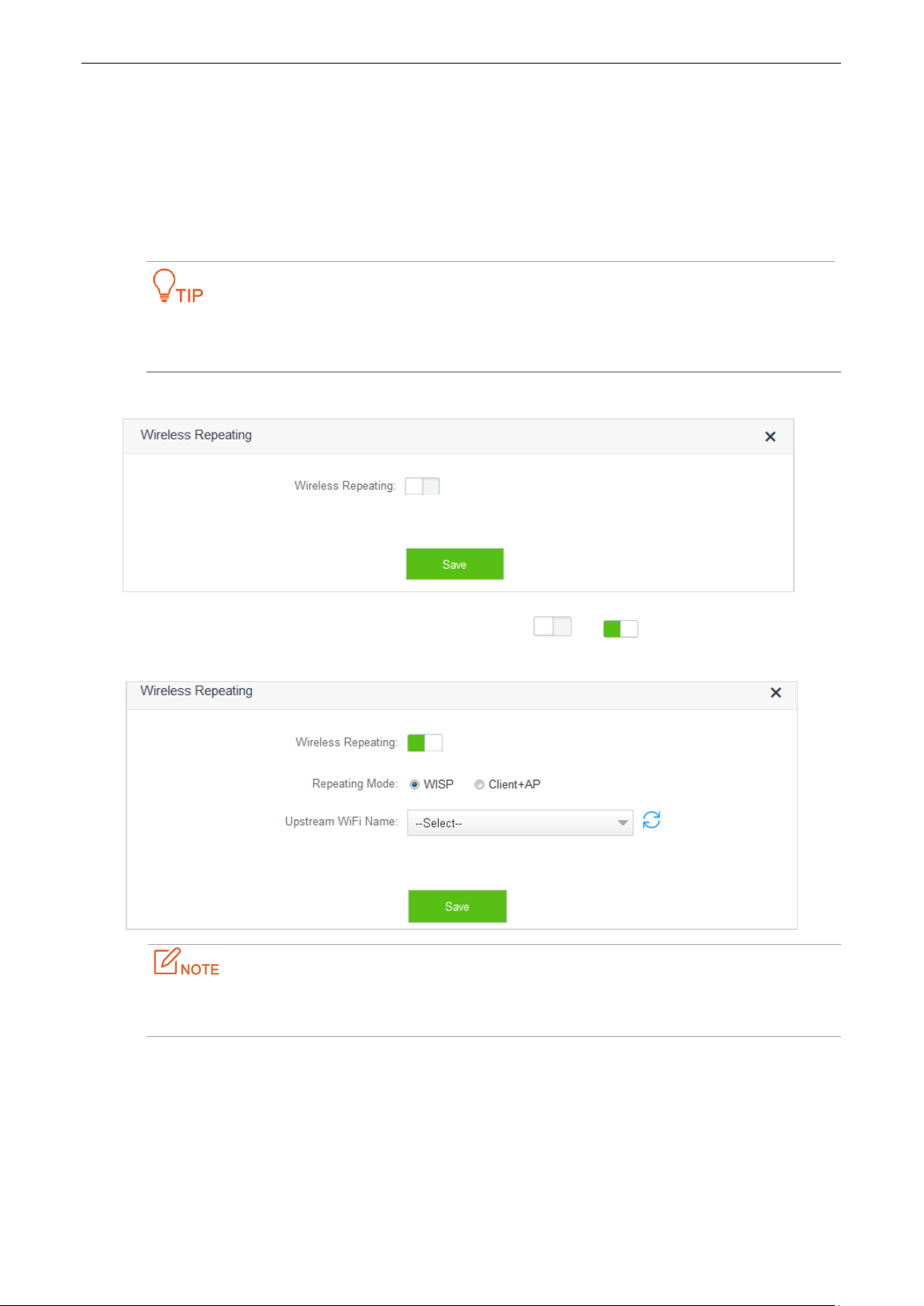
To access the configuration page, click WiFi Settings > Wireless Repeating. By default, the function is disabled.
Enable the function by switching the Wireless Repeating button to . The configuration page is
shown as follows.
If the Wireless Repeating function is enabled, the Sleeping Mode, IPTV, Guest Network, WPS, and WiFi
Schedule functions become unavailable. For details, refer to messages on the web UI of the router.
49
Page 54

Parameter descriptions
Parameter
Description
Wireless Repeating
It specifies whether to enable the Wireless Repeating function.
represents the function is disabled, and is enabled.
Repeating Mode
It specifies the two modes for wireless repeating.
WISP: In this mode, the router repeats wireless signal or wireless
hotspot provided by ISP.
Client+AP: In this mode, the router repeats wireless signal.
Upstream WiFi
Name
It specifies the SSID of the network you want to repeat.
6.3.2 Example
Application Scenario
Michael subscribes to broadband service and purchases a wireless router for network coverage. The router is
placed in the living room. WiFi signals are strong in the living room and master bedroom, but too poor in the
other bedrooms and restrooms to access the internet. Now he wants to extend the wireless network coverage,
ensuring clients to access the internet everywhere.
Solution
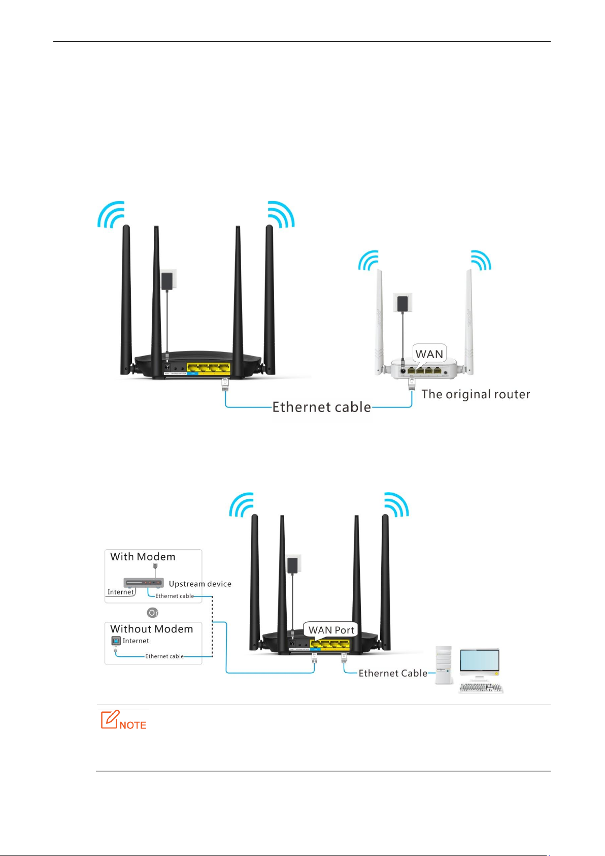
Michael can add an AC5 and configure the Wireless Repeating function of the router to extend WiFi network
coverage of the original router, so clients can access the internet through the WiFi network of AC5. The following
figure shows the application scenario.
50
Page 55

Procedures:
1. To access the configuration page, click WiFi Settings > Wireless Repeating.
2. Wireless Repeating: Switch the button to .
3. Repeating Mode: Select the WISP or Client+AP mode, which is WISP in this example .
4. Upstream WiFi Name: Select WiFi name of the original router from the drop-down list box, which is
Tenda_2 in this example.
5. Upstream WiFi Password: Enter WiFi password of the original router, which is 12345678 in this example.
(If the password is not set on the original router, leave this text box blank.)
6. Click Save.
51
Page 56

7. Click OK.
—End
Verification
After the first figure below appears on the Internet Status page and the second on the Internet Settings,
you can access the internet through the WiFi network of AC5.
52
Page 57

If the original router sets connection type as Dynamic IP Address, the new router obtains
the connection information from the original router automatically. If the connection type
is Static IP Address, you need to configure the connection settings manually.
In the WISP mode, if the LAN IP address of the new router is in the same network segment
as that of the original router, an IP conflict occurs. In that case, the new router replaces
its LAN IP address with another that belongs to another network segment. You can log in
to the web UI of the new router directly by using tendawifi.com.
In the Client+AP mode, the LAN IP address of AC5 changes and you can obtain the new
address from the DHCP Client List of the original router.
6.4 Channel & Bandwidth
6.4.1 Overview
The Channel and Bandwidth function enables you to change network mode, WiFi channel, and WiFi bandwidth
of either 2.4 GHz or 5GHz network. Please retain the default channel and bandwidth settings if you set without
professional guidance. To access the configuration page, click WiFi Settings > Channel & Bandwidth.
53
Page 58

Paremeter
Description
Network
Mode
It specifies a protocol adopted for wireless transmission. You are recommended to
keep the default setting. For 2.4 GHz networks, 11b/g, 11b/g/n, and 11n protocols are
available. For 5 GHz networks, the 11ac and 11a/n/ac are available.
11b/g: It indicates that clients compliant with 802.11b or 802.11g protocol can
connect to the router.
11b/g/n: It indicates that all clients working at 2.4 GHz and compliant with
802.11b, 802.11g, or 802.11n protocol can connect to the router.
11n: It indicates that clients working at 2.4 GHz and compliant with 802.11n can
connect to the router.
11ac: It indicates that clients complaint with 802.11ac protocol can connect to
the router.
11a/n/ac: It indicates that clients working at 5 GHz and compliant with 802.11a,
802.11n or 802.11ac protocol can connect to the router.
WiFi
Channel
It specifies the operating channel of a WiFi network. By default, the channel is chosen as
Auto. It represents the router will view utilization rates of channels and selects one
suitable. But you can change it as required. A channel different from nearby channels and
with less interference are recommended for better wireless transmission efficiency. You
can use a third-party tool to identify the channels different from nearby channels and with
less interference.
Paremeter descriptions
54
Page 59

Paremeter
Description
WiFi
Bandwidth
It specifies bandwidth of the operating channel of a WiFi network. Change the default
settings only when necessary.
20: It indicates that the channel bandwidth of a router is 20 MHz.
40: It indicates that the channel bandwidth of a router is 40 MHz.
20/40: It specifies that a router can switch its channel bandwidth between 20
MHz and 40 MHz based on the ambient environment. This option is available only
to a router working at 2.4 GHz.
80: It indicates that the channel bandwidth of a router is 80 MHz. This option is
available only to a router working at 5 GHz.
20/40/80: It specifies that a router can switch its channel bandwidth among 20
MHz, 40 MHz, and 80 MHz based on the ambient environment. This option is
available only to a router working at 5 GHz.
6.4.2 Changing Channel
Assume that the channel at 2.4 GHz network is required to change to channel 11, and 5 GHz network to
channel 157.
Procedures:
1. To access the configuration page, click WiFi Settings > Channel & Bandwidth.
2. WiFi Channel: In the 2.4 GHz Network part, select Channel 11 from the drop-down list box of WiFi
Channel.
3. WiFi Channel: In the 5 GHz Network part, select Channel 157 from the drop-dwon list box of WiFi
Channel. ( If there is no special requirement about other parameters, retain the default settings.)
4. Click Save.
55
Page 60

—End
6.5 WPS
6.5.1 Overview
The WPS function enables wireless devices, such as smart phones, to connect the WiFi of the router easily and
quickly. To access the configuration page, click WiFi Settings > WPS, then follow the onscreen instructions to
perform.
56
Page 61

6.5.2 Connecting Devices to the WiFi
Smart phones can connect to the router in a WPS manner only if they support the WPS
function.
Desktops or laptops can connect to the router in a WPS manner only if they are installed with
wireless adapters. For detailed information, please refer to the user guide of relevant wireless
adapter.
Method 1: Setting on the Web UI of the Router
1. To access the configuration page, click WiFi Settings > WPS.
2. Click Click Here, then the router’s WIFI LED indicator on the front panel is blinking slowly.
3. Set WPS on a smart phone or computer within two minutes after you click Click Here.
—End
Verification
The smart phone or computer is connected to the WiFi of the router successfully after a while.
57
Page 62
Method 2: Setting via the WPS Button on the Router
1. Press the WPS button on the router.
2. Set WPS on a smart phone or computer within two minutes after you press the button.
—End
Verification
The smart phone or computer is connected to the WiFi successfully after a while.
58
Page 63
Method 3: Setting via Pin Code of the Router
If use this method on a computer, you are recommended to install it with a wireless adapter with PIN.
For more information, refer to the user guide of corresponding wireless adapter.
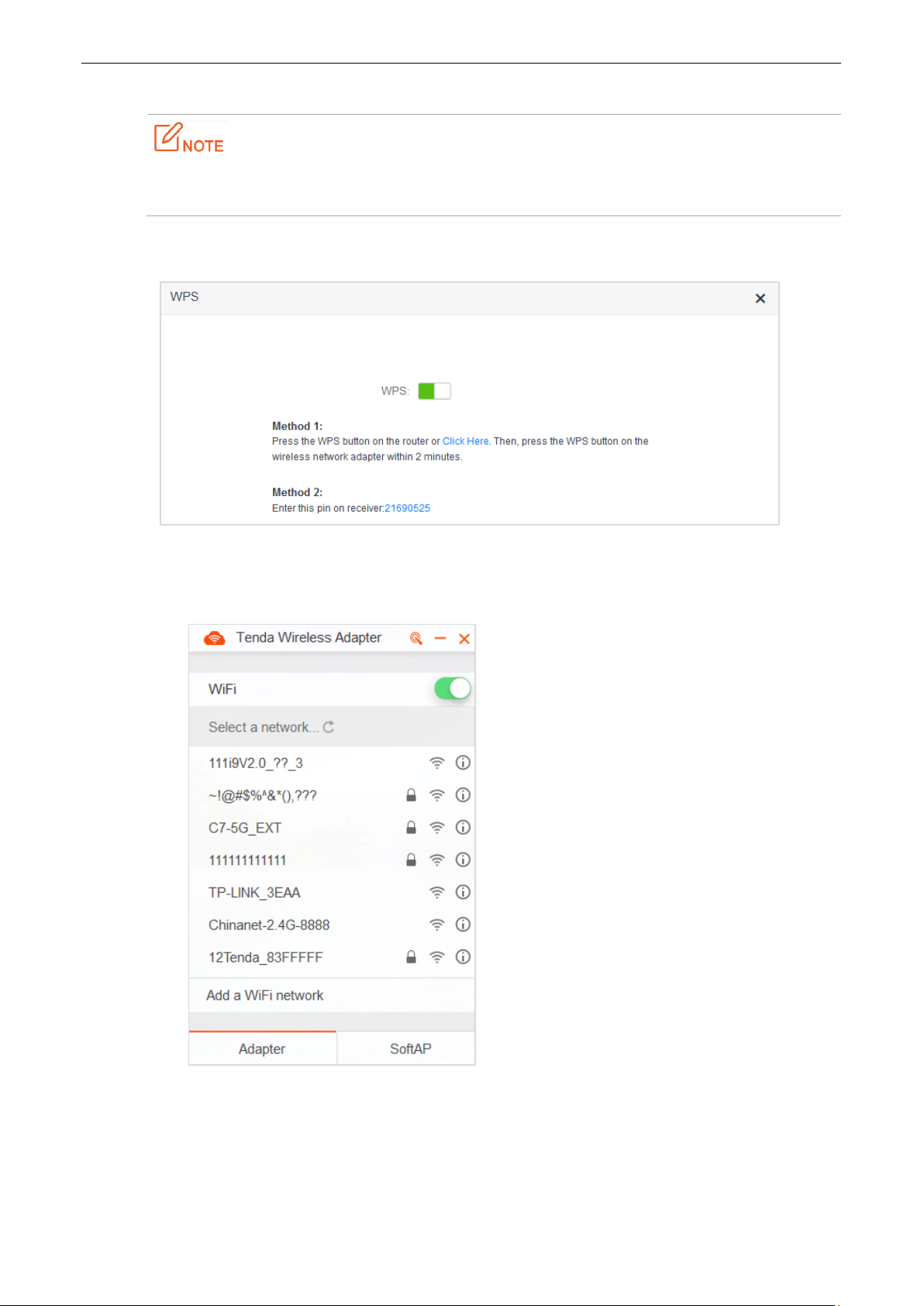
1. To access the configuration page, click WiFi Settings > WPS.
2. Record the WPS PIN code of the router, which is 21690525 in this example.
3. Enter the PIN code on the device for connection. (Taking a computer with a wireless adapter as an
example)
(1) Open the wireless adapter app on your computer.
59
Page 64

(2) Click the icon on the upper right part of the app. Then the figure below appears.
(3) On the item Connection Type, click the drop-down list button, and choose PIN Code.
(4) Enter the Pin code, which is 21690525 in this example. Click Connect.
60
Page 65

(5) Connected. Your computer can access the internet through the router.
—End
6.5.3 Example
Application Scenario
Michael purchases an AC5 for wireless network and he has set the WiFi password. But he hopes to access the
internet through the router without entering password. Assume that the WiFi name of the router is
Tenda_097190.
The WPS function can address this requirement.
Procedures:
1. Set the router.
(1) To access the configuration page, click WiFi Settings > WPS.
(2) Click Click Here.
61
Page 66

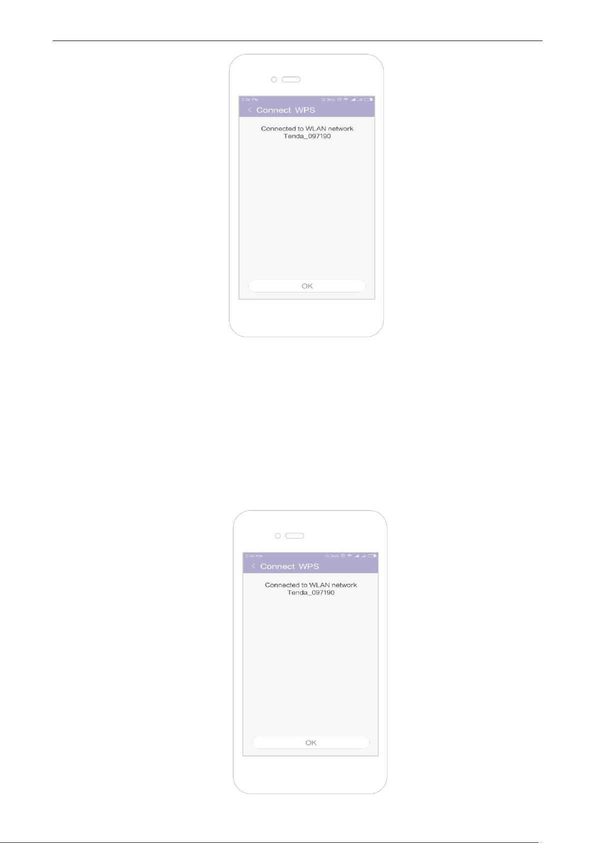
2. Set WPS on a smart phone, which is Redmi Note 4X in this example.
(1) Choose Settings on the homepage of the smart phone.
(2) Then click WLAN > Advanced Settings > Connect WPS.
62
Page 67

(3) The smart phone is performing WPS negotiation with the router.
—End
Wait a moment for the connection to complete.
Verification
The smart phone connects to the WiFi of the router successfully.
63
Page 68

6.6 Beamforming+
6.6.1 Overview
As a wireless signal optimization technology, the location-oriented Beamforming could transmit wireless
signals to wireless devices precisely, offering users with better internet connection, such as faster download or
playback of HD videos.
Wireless routers broadcast signals to all directions if they do not support Beamforming+.
Wireless routers supporting Beamforming+ could transmit wireless signals toward the location of
each client, improving users’ internet experiences.
The following figure shows the wireless transmission when Beamforming+ is disabled.
64
Page 69

The following figure shows the wireless transmission when Beamforming+ is enabled.
6.6.2 Setting Beamforming+
To access the configuration page, click WiFi Settings > Beamforming+.
By default, the Beamforming+ function is enabled. It is recommended to retain default settings.
6.7 AP Mode
6.7.1 Overview
In the AP mode, the router functions as a wireless access point (AP), and WAN port of the router functions as a
LAN port. Usually, in the AP mode, when the router connects to the upstream router using an Ethernet cable, the
router extends the wireless network coverage of the upstream router, or transforms the wired signals to wireless
ones.
65
Page 70

To access the configuration page, click WiFi Settings > AP Mode. By default, this function is disabled.
6.7.2 Enabling AP Mode
1. To access the configuration page, click WiFi Settings > AP Mode.
2. AP Mode: Switch the button to .
3. Click Save.
—End
After the AP Mode is enabled, the Internet Settings, IPTV, Parental Control, Bandwidth Control,
Virtual Server functions become unavailable.
The LAN IP address of the router changes once the AP Mode is enabled. Please log in to the
web UI of the router by tendadwifi.com, or you could log in to the web UI of the upstream
router to view the new IP address of the router, and try logging in again.
66
Page 71

6.7.3 Example
Application Scenario
Michael could access the internet through his optical modem using Ethernet cable. But now he wants to access
the internet by WiFi.
Solution
AC5 in the AP mode enabled could address this requirement. After configuration, wireless devices such as
smart phones can access the internet through the WiFi of AC5.
The following figure shows the application scenario.
Connect the optical modem to any port of the router using an Ethernet cable. Connect smart phones to the
router’s WiFi and the computer to the router using Ethernet cable.
Procedures:
1. To access the configuration page, click WiFi Settings > AP Mode.
2. Switch the AP mode button to .
3. Click Save.
67
Page 72

4. Click Ok in the following window that appears.
—End
Verification
Computers connected to the router using cable, or wireless devices such as smart phones, connected to the
router’s WiFi could access the internet normally.
6.8 Anti-interference
This router supports the Anti-interference function. By default, this function is auto. When you have bad
internet experience, please try to modify the Anti-interference settings.
To access the configuration page, click WiFi Settings > Anti-interference.
68
Page 73

When you choose Auto, the router will adjust receiving sensitivity automatically based on the
current interference. Please keep Auto if you do not have special requirements.
When you choose Disable, the router has wider WiFi coverage. But if the interference is strong in
your environment, you are recommended to choose Auto or Enable.
When you choose Enable, the router has better anti-inference ability but smaller WiFi coverage.
69
Page 74
Parameter
Description
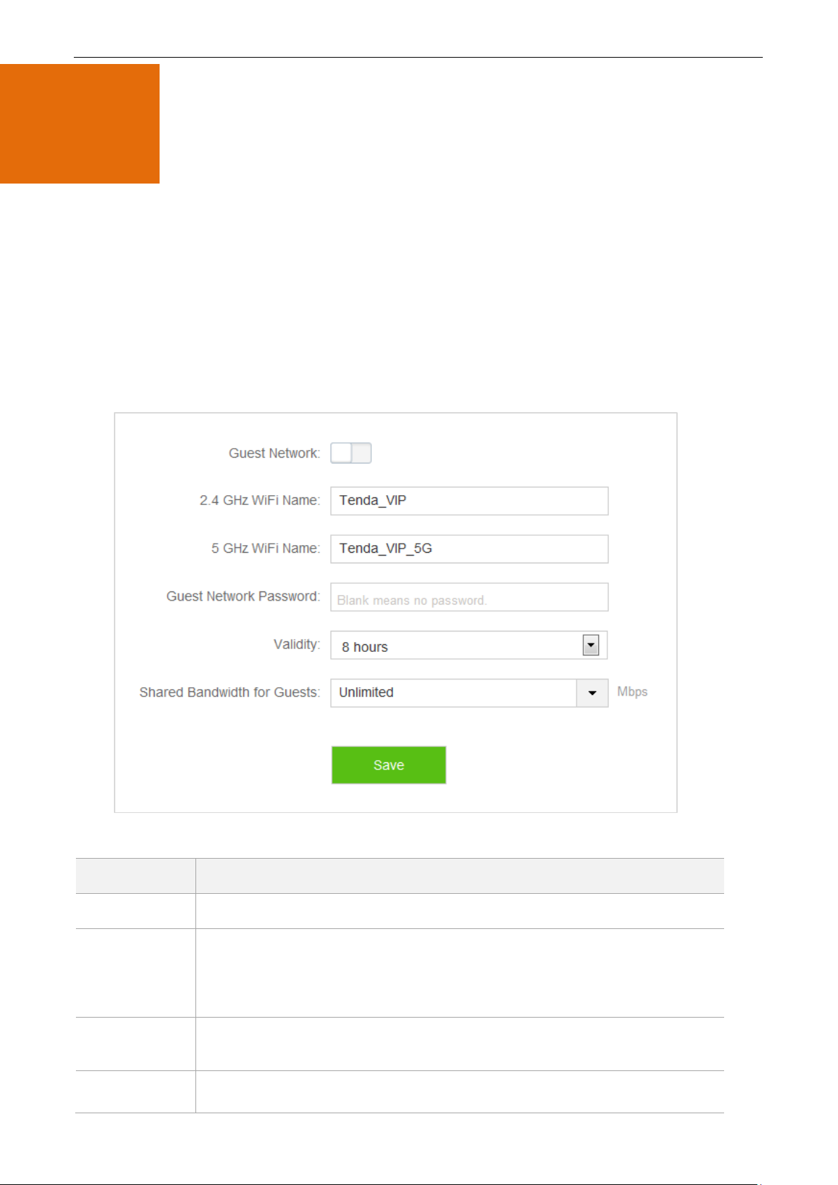
Guest Network
It specifies whether to enable the Guest Network function.
2.4 GHz /5 GHz
WiFi Name
It specifies the 2.4 GHz/5 GHz WiFi name of the guest network. By default, Tenda_VIP
is for 2.4 GHz network and Tenda_VIP_5G for 5 GHz network. You can change WiFi
names if required. To distinguish guest network from non-guest network, you are
recommended not to set the same names for these two networks.
Guest Network
Password
It specifies the passwords for the router’s two guest networks. Please set according
to your requirements.
Validity
It specifies the validity of guest network. It represents the Guest Network function
will be disabled automatically in specified time so wireless devices will not search it.
7
Guest Network
7.1 Overview
This module makes you enable/disable the Guest Network function and change Guest Network’s WiFi name
and password.
Devices connected to the guest network can access to the internet and communicate with each other, but
cannot access the router’s web UI or the master network. This function enables guests to access the internet and
ensures security of the master network.
To access configuration page, click Guest Network. The Guest Network function is disabled by default.
Parameter descriptions
70
Page 75
Parameter
Description
Please set according to your requirements.
Shared
Bandwidth for
Guests
It specifies downloading speed of guest network devices, with a unit Mbps. By
default, the speed is not limited. You can set according to your requirements.
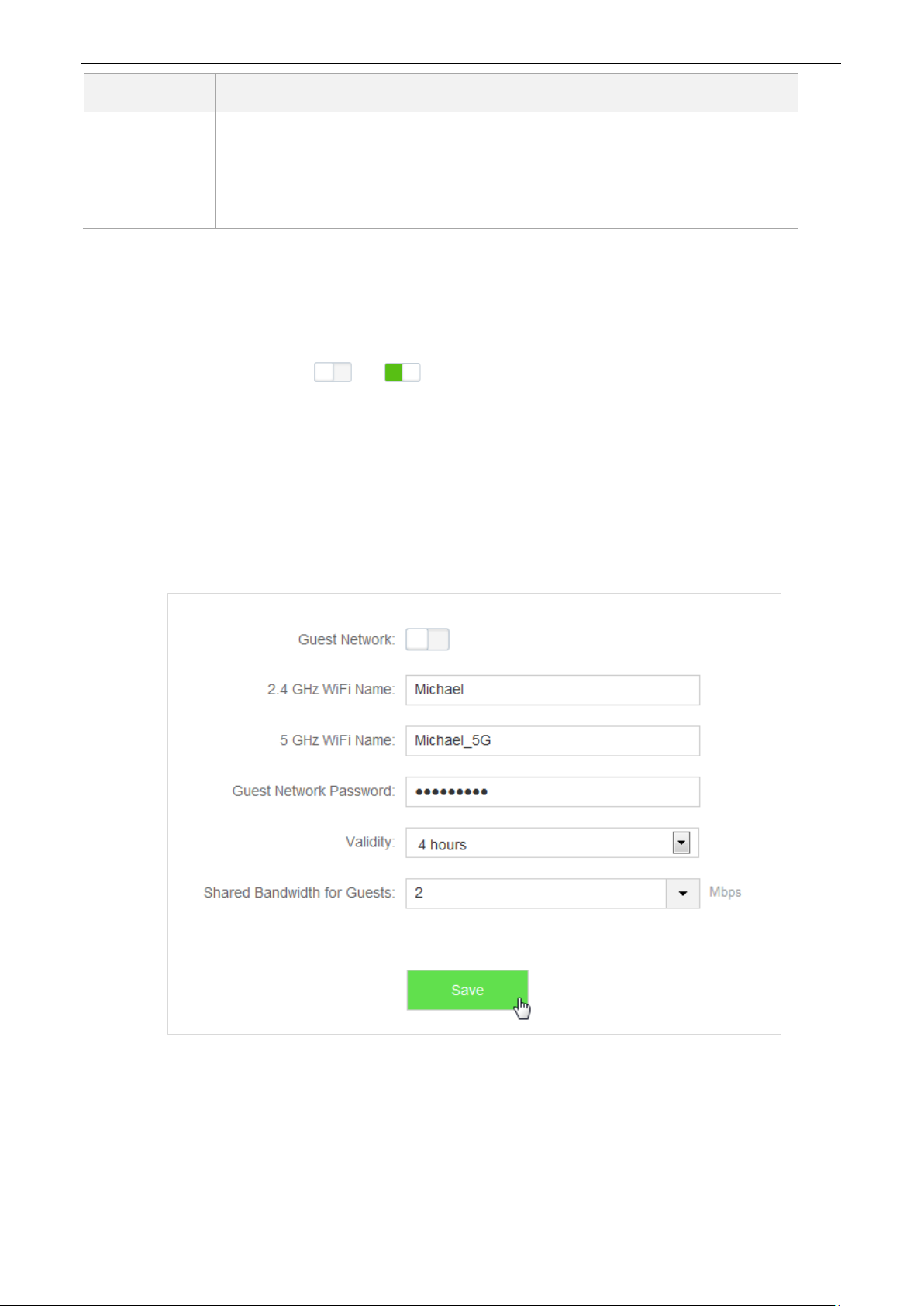
7.2 Setting Guest Network
1. To access the configuration page, click Guest Network.
2. Guest Network: Switch to .
3. 2.4GHz WiFi Name: Change the WiFi name, which is Michael in this example.
4. 5GHz WiFi Name: Change the WiFi name, which is Michael_5G in this example.
5. Guest Network Password: Set password, which is 987654321 in this example.
6. Validity: Select from the drop-down list box, which is 4 hours in this example.
7. Shared Bandwidth for Guests: Click drop-down box, and select 2.
8. Click Save.
—End
After configuration, wireless devices, such as smart phones, connected to Michael or Michael_5G share a
downloading speed up to 2 Mbps, and can access the internet consecutively for4 hours.
71
Page 76

Parameter
Description
Device Name
It specifies name of the device connected to the router.
MAC Address
It specifies MAC address of the device connected to the router.
Uptime
It specifies the time that has elapsed since the device was previously connected to
the router.
Operation
Click to set limits for devices to access the internet through the router.
+New
Click +New to add devices and set limits for them.
8
Parental Control
8.1 Overview
This module enables you to set the internet accessibility of devices in LAN network, including specified time for
surfing the internet, websites allowed or banned to visit.
To access configuration page, click Parental Control. The following page shows a device connected to the
router currently.
Parameter descriptions
8.2 Setting a Parental Control Rule
8.2.1 Scenario 1: The Device Has Connected to the Router
1. Click Parental Control.
2. In device list, locate the device you want to apply the rule to, click .
72
Page 77
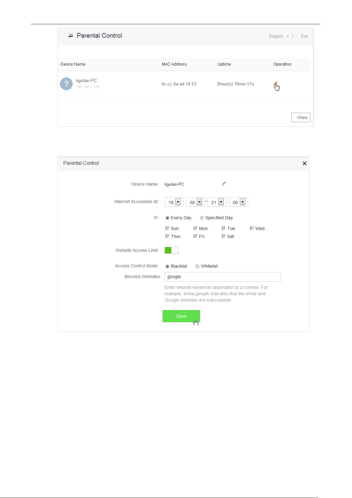
3. Set valid time for internet connection, and accessible or inaccessible websites.
4. Click Save.
—End
8.2.2 Scenario 2: The Device has not Connected to the Router
1. Click Parental Control.
2. Click +New.
73
Page 78
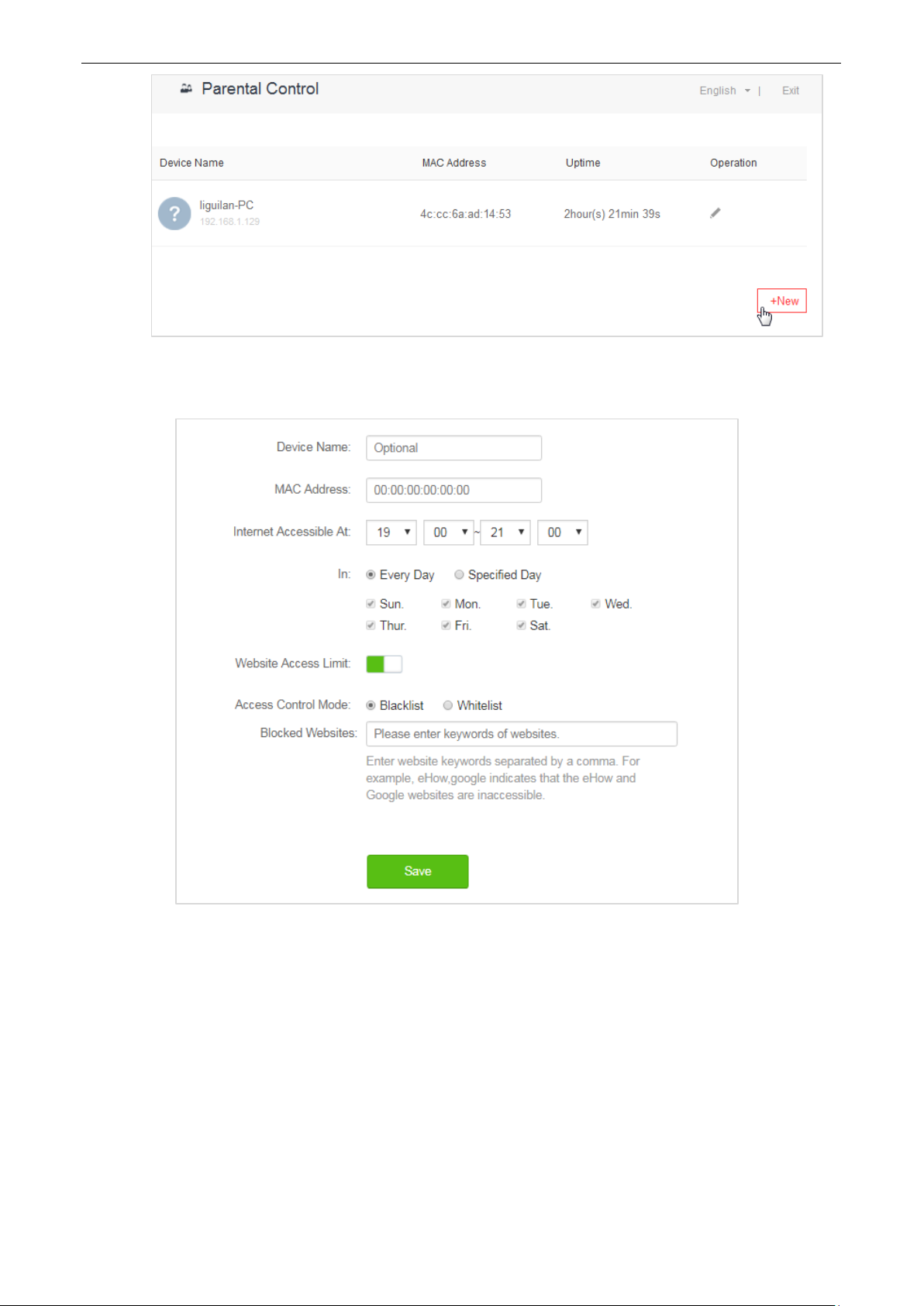
3. Set device name, MAC address, time limit for internet access and limit for website access as required.
4. Click Save.
—End
74
Page 79

Parameter descriptions
Parameter
Description
Device Name
It specifies name of the device you want to apply the rule to.
MAC Address
It specifies MAC Address of the device you want to apply the rule to.
Internet Accessible
At
It specifies specific time for devices to access the internet through the router.
In
It specifies dates for devices to access the internet.
Website Access
Limit
It specifies whether to enable the website access limit function. By default, this
function is enabled.
Access Control
Mode
It specifies modes for website access limit in parental control rules.
Blacklist: Only this device is banned to visit the websites listed in the
rules.
Whitelist: This device is only allowed to visit the websites listed in the
rules.
Blocked/Unblocked
Websites
It specifies the websites that devices are banned/ allowed to visit in Internet
Accessible At.
8.3 Example
Application Scenario
Michael bought an AC5 for network, but his children always visited websites on the phone connected to the
router. For the good of his children’s learning, he intends to allow his children to access Google during 8:00-22:00
from Monday to Friday.
Solution
The Parental Control function of AC5 can address this requirement.
Procedures:
1. Click Parental Control.
2. In device list, locate the device you want to apply the rules to and click .
75
Page 80

3. Internet Accessible At: Set time period for devices to access the internet, which is 08:00-20:00 in this
example.
4. In: Select Specified Day, and choose Monday-Friday as well.
5. Access Control Mode: Choose Whitelist.
6. Unblocked Websites: Enter the website accessible to the device, which is google in this example.
7. Click Save.
—End
Verification
The device could access Google only during 8:00-20:00 from Monday to Friday.
76
Page 81

9
The VPN module includes PPIP Server, Online PPTP Users, and PPTP/L2TP Client.
VPN (Virtual Private Network) is a dedicated network across the shared or public network (usually the internet).
However, since this dedicated network does not have physical lines but only exists logically, it is called the virtual
private network. VPN technology allows employees at a branch of an enterprise and employees at the
headquarters to exchange resources conveniently without exposing these resources to other internet users.
VPN
9.1 PPTP Server
9.1.1 Overview
On the PPIP Server page, you can set the router as PPIP server.
PPTP server allows the specified VPN users to dial in.
For example, enabling the PPTV server function of the headquarter’s router allows staffs on business trip to
access the headquarter’s resources through VPN dialing up.
To access the configuration page, choose VPN > PPTP Server.
77
Page 82

Parameter
Description
PPTP Server
It specifies whether to enable the PPTP server function. If the function is enabled,
the router functions as a PPTP server.
IP Address
Pool
It specifies the range of IP addresses that PPTP server can assign to devices.
MPPE
Encryption
It specifies whether to enable MPPE encryption function.
User Name
Set user name and password that is allowed to dial in PPTP server. This name and
password is used when device is connected to PPTP server.
Password
Connection
Status
It specifies the status of a VPN connection.
Operation
The following operations can be performed on the rules:
: It is used to add PPTP users.
: It is used to disable PPTP users.
: It is used to enable PPTP users.
: It is used to delete PPTP users.
Enable PPIP Server. The figure below shows the dialog box that appears after the function is enabled.
Parameter descriptions
78
Page 83

9.1.2 Example
Application Scenario
Michael bought an AC5 for network. He needs to access the resources on his computer’s FTP server at home.
Solution
The PPTP server function of AC5 can address this requirement.
Set PPTP Server function on the router. He can access to resources on the computer’s FTP server by VPN
dialing up on business trip. Assume that the IP address of the FTP server is 192.168.0.104:21, and the WAN IP
address of the router is 113.88.112.220. After the PPTP server function of the router is enabled, the WAN IP
address becomes the address of the PPTP server.
Procedures:
1. To access the configuration page, choose VPN > PPTP Server.
2. PPTP Server: set to .
3. IP Address Pool: Set the range of IP addresses that the PPTP server assigns to devices. You are
recommended to keep default settings.
4. MPPE Encryption: Enable MPPE encryption, and set the number of MPPE encryption bits, which is 128
in this example.
5. User Name, Password: Set user names and passwords that devices use for VPN dialing up, both of
which are admin1 in this example.
6. Click +New.
7. Click Save.
—End
79
Page 84

Verification (Example: Windows 7)
On business trip, Michael succeeds in accessing resources on his computer’s FTP server at home. The following
describes the steps:
1. Click at the bottom-right corner of the desk, and click Open Network and Sharing Center.
2. Click Set up a new connection or network.
80
Page 85

3. Click Connect to a workplace > Next.
4. Click Use my Internet connection (VPN). If a dialog box appears, you can follow the onscreen instruction
to perform operations.
81
Page 86

5. Enter the IP address of the PPTP server in the Internet address text box, which is 113.88.112.220 in this
example. Then click Next.
6. Enter the user name and password for connecting to the PPTP server, which are admin1 in this example.
Click Create.
82
Page 87

7. Click Connect Now after a while.
8. Access the resources on the FTP Server at home by the server here or My Computer.
Method: “ftp: //Server IP address: Service port number”, which is ftp: //192.168.0.104:21 in this example.
83
Page 88

Access successfully. See the following figure.
Parameter
Description
User Name
It specifies the name for a user to dial in the PPTP server.
Dial-In IP
Address
It specifies device’s IP address. If the client is a router, IP address of the WAN port
which enables VPN function will be showed.
Assigned IP
Address
It specifies the IP address that the PPTP server assigns to device.
9.2 Online PPTP Users
On the Online PPTP Users page, you can have detailed information about the VPN clients dialed in the PPTP
server.
To access the configuration page, select VPN > Online PPTP Users.
Parameter descriptions
84
Page 89

Parameter
Description
Uptime
It specifies the time that has elapsed since the PPTP device previously dialed in the
server successfully.
9.3 PPTP/L2TP Client
9.3.1 Overview
You are allowed to set router as a PPTP/L2TP client on the PPTP/L2TP Client page.
The router can connect to the PPTP/L2TP server after the PPTP/L2TP Client function is enabled. Example: If
users subscribe to the VPN service provided by their ISP when having broadband, they can dial in their ISP’s VPN
network through the PPTP/L2TP Client function of the router. To access the configuration page, click VPN >
PPTP/L2TP Client.
Enable PPTP/L2TP Client. See the following figure.
85
Page 90

Parameter descriptions
Parameter
Description
PPTP/L2TP Client
It specifies whether to enable PPTP/L2TP client function. If the function is
enabled, the router functions as a VPN client.
Client Type
It specifies whether the router is a PPTP client or an L2TP client.
Server IP Address
/Domain Name
It specifies the IP address or domain name of the PPTP/L2TP server to which the
router is to be connected.
User Name
It specifies the user name and password assigned by the PPTP/L2TP server to the
PPTP/L2TP client.
Password
Status
It specifies the current connection status of a VPN client.
9.3.2 Example
Application Scenario
Michael subscribed to VPN service (PPTP or L2TP) provided by ISP when he had broadband, which is PPTP
service in this example. Assume that the VPN service information provided by his ISP is as follows:
PPTP Server Address: 1.1.1.1
User name/Password: 123
Michael bought an AC5 for network. He wants to access the VPN resources provided by his ISP.
Solution
The PPTP Client function could address this requirement. Set the PPTP Client function on the router. Clients in
LAN network could access the VPN resources provided by the ISP.
Procedures:
1. To access the configuration page, click VPN > PPTP/L2TP Client.
2. PPTP/L2TP Client: Switch the button to .
3. Client Type: Select client type, which is PPTP in this example.
4. Server IP/Domain Name: Enter PPTP server IP address or domain name, which is 1.1.1.1 in this
example.
5. User Name, Password: Set user name and password client uses for VPN dialing up, which are 123 in this
example.
6. Click Connect.
86
Page 91
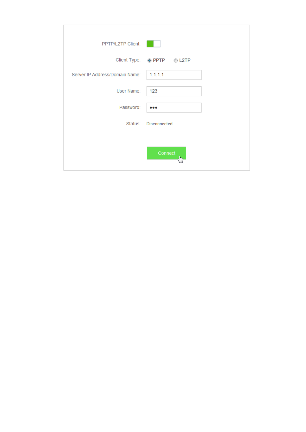
—End
Verification
Clients in LAN network could access the VPN resources provided by the ISP.
87
Page 92

Parameter
Description
Device Name
It presents information about a client that has connected to the router, including
name, IP address. Name of a client can be changed if you click .
Upload/Download
Speed
It specifies the current upload and download speeds of a device.
Upload/Download
Limit
It specifies the maximum upload/download speed of a client. You can set the
maximum upload/download speed for a device by clicking drop-down box, and
selecting speed you prefer or entering speed manually.
10
This module includes: Bandwidth Control, Tenda App, Sleeping Mode, LED Control, Filter MAC Address,
Firewall, IPTV, Static Route, DDNS, Virtual Server, DMZ Host, and UPnP.
Advanced Settings
10.1 Bandwidth Control
10.1.1 Overview
On the Bandwidth Control page, you can view information about online devices, and set upload limit or
download limit for clients if needed. To access the configuration page, click Advanced Settings > Bandwidth
Control.
Parameter descriptions
88
Page 93
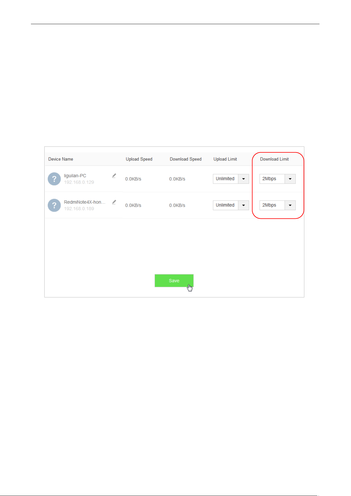
10.1.2 Example
Application Scenario
Michael bought an AC5 for network after having broadband. He needs to set download limit for every device
to ensure all family members have good internet experience.
Procedures:
1. To access the configuration page, click Advanced Settings > Bandwidth Control.
2. Set Download Limit to a value for the devices in the list, which is 2 Mbps in this example.
3. Click Save.
—End
Verification
The maximum download speed for each device in the list is 2Mbps, which allows each device to see HD videos
and surf the internet properly.
89
Page 94
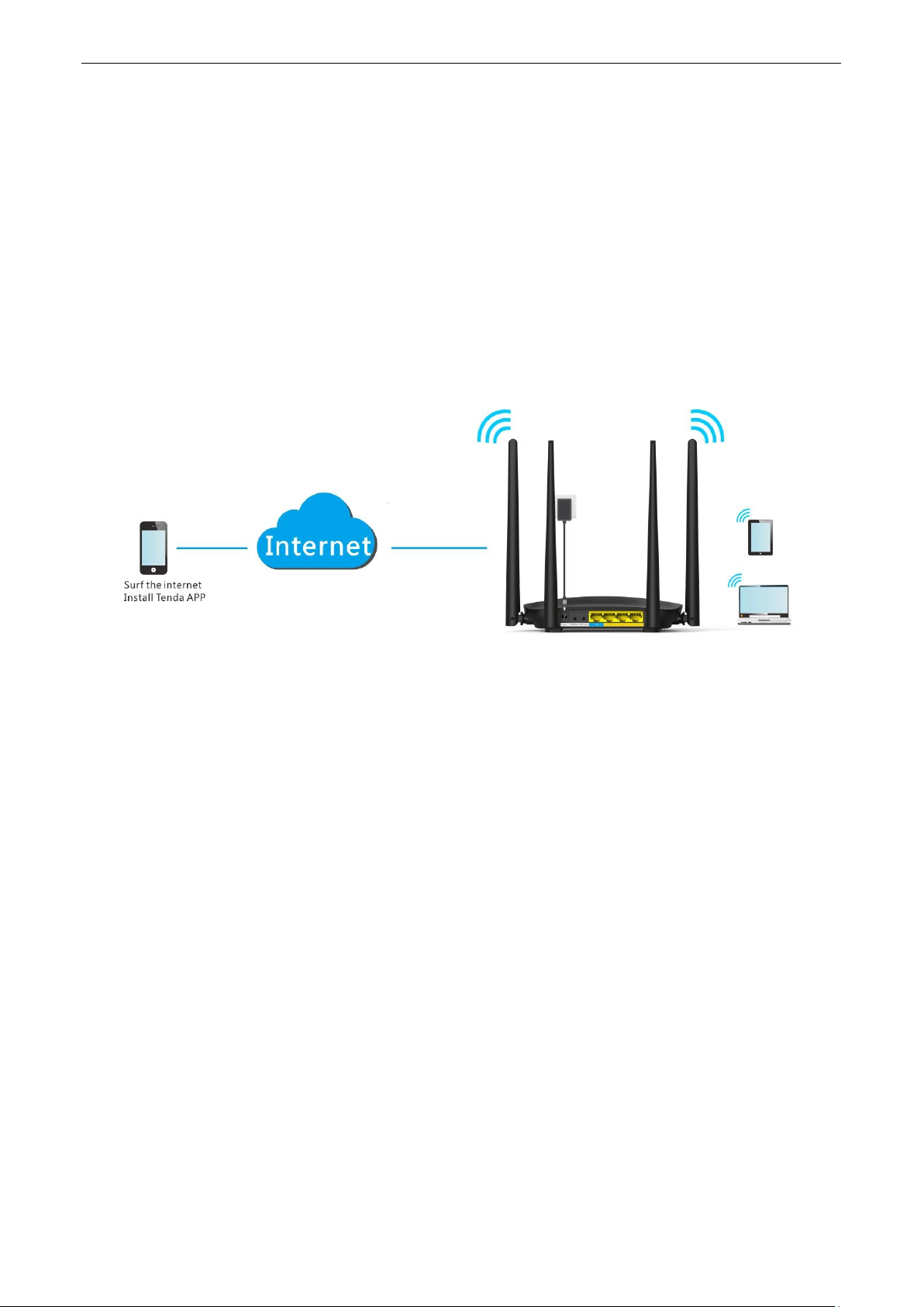
10.2 Tenda App
This router supports app management, so you can manage it wherever and whenever you are. You can use
Tenda WiFi app to:
Manage router in LAN.
Manage router remotely over the internet.
To access the configuration page, click Advanced Settings > Tenda App.
10.2.1 Example
The following figure may help you understand the application scenario. (Example: Managing the router remotely)
Procedures:
1. Install Tenda WiFi app.
(1) Download Tenda WiFi in app store of your phone.
2. Register a Tenda account.
(1) Open Tenda WiFi and enter the login password of your router (if any) in the password box.
(2) Click Login.
90
Page 95
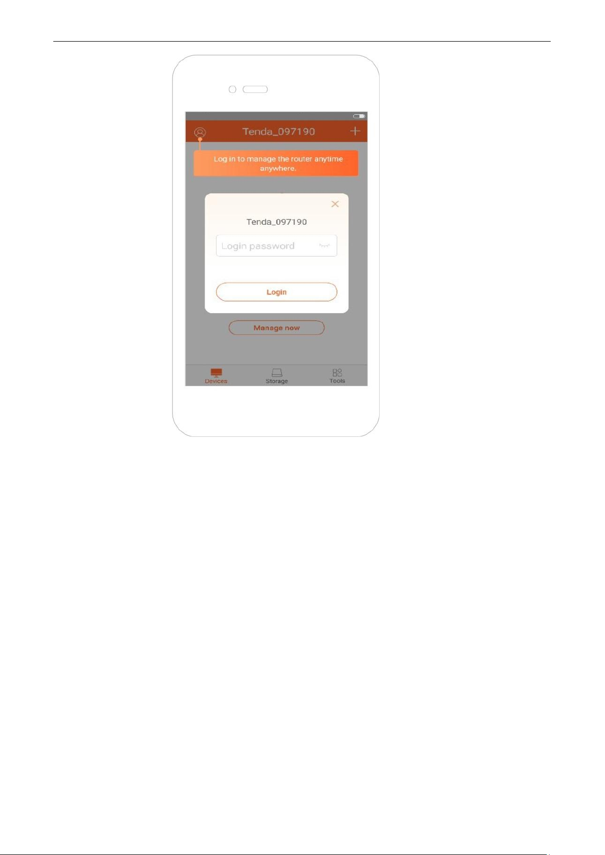
91
Page 96

(3) Choose for registration.
(4) Email Address: Enter the email address you want to set as account name. Assume that the email
address in this example is 12345678901@163.com.
(5) Password: Set password for your Tenda account.
(6) Click Register.
(7) The activation email has sent to your email address. Please tap click here to confirm to activate in
valid time.
(8) Your account is activated successfully.
92
Page 97

3. Log in to the web UI of the router, and enable the Tenda App function.
(1) Click Advanced Settings > Tenda App.
(2) Manage with Tenda App: Switch the button to .
(3) Account: Enter the account registered in your Tenda WiFi on phone, which is email address in this
example.
(4) Click Save.
When you are not at home, you can have Tenda app to manage the router by connecting smart phone to WiFi
or traffic.
93
Page 98

Parameter
Description
Sleeping Mode
It specifies whether to enable/disable the Sleeping Mode function.
When the router is in Sleeping mode, you can enable the WiFi function by pressing
10.3 Sleeping Mode
This router supports the Sleeping Mode function. When the function takes effect, the LED indicators and WiFi
will be turned off.
The Sleeping Mode function works based on time settings. If the system time of the router is not
synchronized with the internet time, the function cannot work properly.
To access the configuration page, click Advanced Settings > Sleeping Mode. By default, the function is disabled.
The figure below shows the page after this function is enabled.
Parameter descriptions
94
Page 99

Parameter
Description
the WiFi on/off button on the rear panel of the router or using Tenda app. For details
about how to enable this WiFi function by Tenda app, refer to the Tenda app usage.
Sleeping Time
It specifies time when the Sleeping Mode function is effective.
Delay
If Delay enabling the Sleep mode when there is an online user option is
selected and client exchanges data with the router in a WAN speed of no more
than 3KB/s within 30 minutes, the router enters Sleeping mode. If no client
exchanges data with the router, and the traffic is less than 3 KB/s within 3
minutes, the router enters Sleeping mode.
If Delay enabling the Sleep mode when there is an online user option is not
selected, the router enters Sleeping mode during Sleeping Time after Sleeping
Mode is enabled.
Parameter
Descriptions
Always on
It indicates that all the LED indicators are on.
Always off
It indicates that all the indicators are off.
Schedule
It specifies that all the LED indicators are off in the period Turn Off During and become
enabled when the periods expire.
10.4 LED Control
On the LED Control page, you can set the on/off status of the router’s LED indicators.
To access the configuration page, click Advanced Settings > LED Control.
Parameter descriptions
95
Page 100
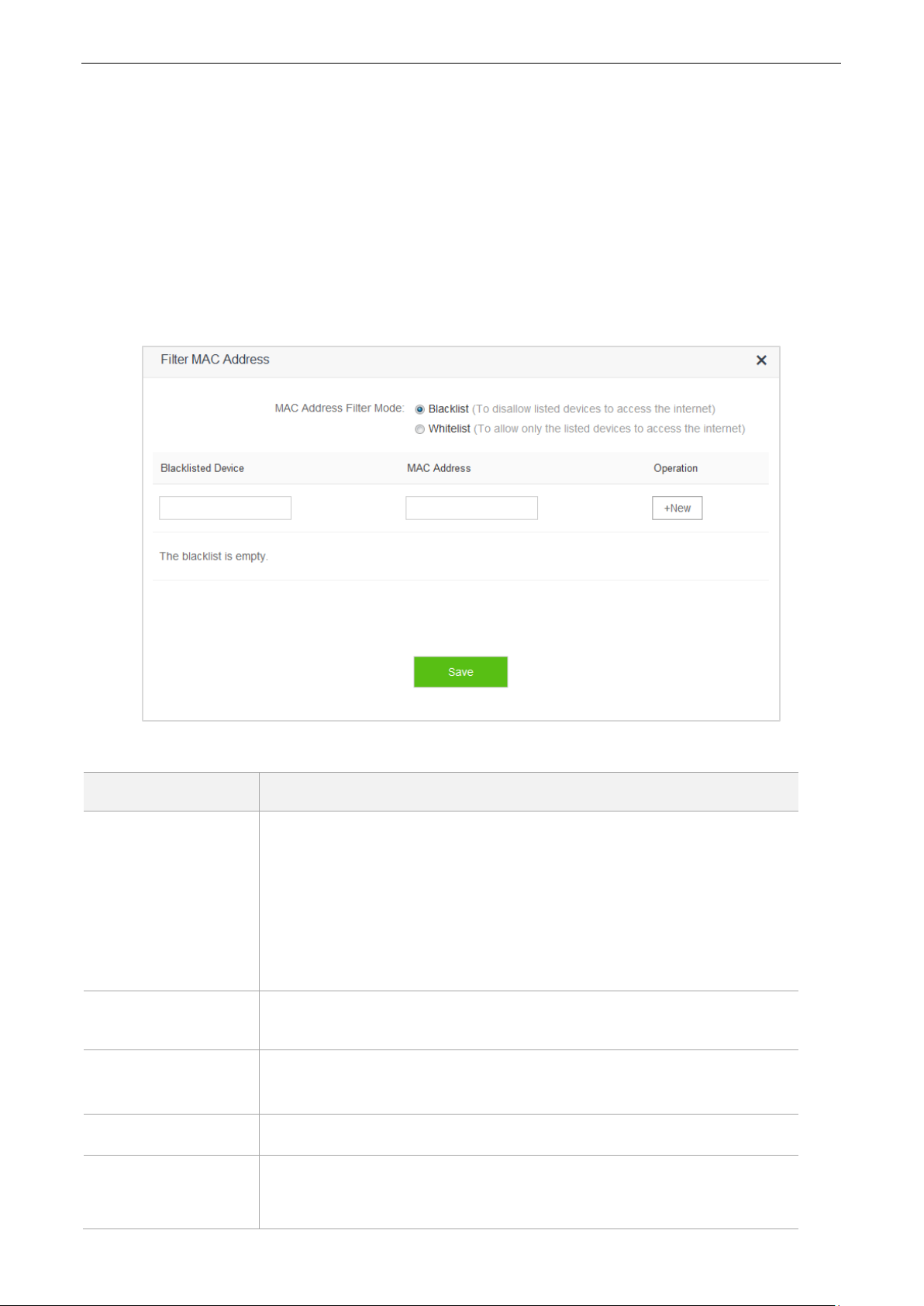
10.5 Filter MAC Address
Parameter
Description
MAC Address Filter
Mode
It specifies whether the listed devices are allowed to access the internet
through the router.
Whitelist: It specifies that only the listed devices can access the
internet through the router.
Blacklist: It specifies that the listed devices cannot access the
internet through the router.
Blacklisted/Whitelisted
Device
It specifies that you can set devices you want to add in blacklist or whitelist.
MAC Address
It specifies that you can enter MAC addresses of devices you want to add in
blacklist or whitelist.
Operation
It specifies that you can add clients in blacklist/whitelist by clicking +New.
Add all online devices
to whitelist
This option is only available for Whitelist.
It specifies that you can add all online devices to whitelist by clicking this link.
10.5.1 Overview
Computers and smart phones have their own MAC addresses.
On the Filter MAC Address page, you can add filter rule and set limit for MAC address to access the internet,
including To disallow listed devices to access the internet and To allow only the listed devices to access the
internet.
To access the configuration page, click Advanced Settings > Filter MAC Address.
Parameter descriptions
96
 Loading...