

Page 1

Install Guide
Copyright Statement
is the registered trademark of Shenzhen Tenda
Technology Co., Ltd. All the products and product names
mentioned herein are the trademarks or registered trademarks of
their respective holders. Copyright of the whole product as
integration, including its accessories and software, belongs to
Shenzhen Tenda Technology Co., Ltd. No part of this publication
can be reproduced, transmitted, transcribed, stored in a retrieval
system, or translated into any language in any form or by any
means without the prior written permission of Shenzhen Tenda
Technology Co., Ltd. If you would like to know more about our
product information, please visit our website at
http://www.tendacn.com
Disclaimer
Pictures, images and product specifications herein are for
references only. To improve internal design, operational function,
and/or reliability, Tenda reserves the right to make changes to the
products described in this document without obligation to notify
any person or organization of such revisions or changes. Tenda
does not assume any liability that may occur due to the use or
application of the product or circuit layout(s) described herein.
Every effort has been made in the preparation of this document
to ensure accuracy of the contents, but all statements,
information and recommendations in this document do not
constitute the warranty of any kind, express or implied.
i
Page 2

Install Guide
Preface
Brief Introduction to This Manual:
Chapter 1 Product Overview
Introduction to switch features and its physical description.
Chapter 2 Preparation
Introduction to the installation site, notes for installation and tools for
installation.
Chapter 3 Installation
Introduction to the switch’s installation, power supply connection,
interface cable connection and check-ups after the installation.
Chapter 4 Starting the Device
Introduction to the switch’s starting and configuration, including the
configuration preparation, console cable connection, port settings
on the terminal, the device starting, etc.
Chapter 5 Web Login
Introduction to the switch’s login methods.
Chapter 6 Troubleshooting
Information about troubleshooting the switch.
ii
Page 3

Install Guide
Safety Guidelines
Use the following safety guidelines to ensure your own personal
safety and to help protect your system from potential damage.
Basic
1. Keep the device strictly dry while storing, shipping and using;
2. Keep the device from fierce collision;
3. Follow the instructions provided in this manual to install the
device;
4. Please contact the specified maintenance staff rather than
remove the device on your own if any fault happens.
5. We reserve the right to revise this publication and to make
changes in the content hereof without obligation to notify any
person or organization of such revisions or changes;
Environmental Requirements
1. Temperature - Install the switch in a dry area, with ambient
temperature between 0 and 40ºC (32 and 104ºF). Keep the
switch away from heat sources such as direct sunlight, warm
air exhausts, hot-air vents, and heaters.
2. Operating humidity - The installation location should have a
maximum relative humidity of 90%, non-condensing.
3. Ventilation - Do not restrict airflow by covering or obstructing air
inlets on the sides of the switch. Keep it at least 10cm free on
all sides for cooling. Be sure there is adequate airflow in the
room or wiring closet where the switch is installed.
4. Operating conditions - Keep the switch away from nearest
source of electromagnetic noise, such as a photocopy machine,
microwaves, cellphones, etc.
iii
Page 4

Install Guide
Use Notes
1. Use the provided accessories, such as the cable, mounting kit,
etc.
2. Ensure the basic supply voltage standard must be met.
3. Keep the power plug clean and dry in case of electric shock or
other dangers.
4. Keep your hands dry while plugging cables.
5. Shut down the device and power it off before plugging cables.
6. Disconnect the power supply and pull out all cables, such as
the power cord, fiber, Ethernet cable, etc. in lightening days.
7. Disconnect the power supply and pull out the plug if the device
is out of use for a long time.
8. Keep the device far from water or other liquids.
9. Contact the specified maintenance staff if any problem occurs.
10. Do Not thread on, drag or excessively bend its cable.
11. Do Not use broken or aged cables.
12. Do Not look the fiber interface in your eyes in case of eye
damage.
13. Prevent some matters, such as metals, from entering the
device through the ventilation hole.
14. Do Not scrape or fray the device shell in case of abnormal
operation or human body allergic.
15. Keep the device out of children’s reaches.
Cleaning Notes
1. Shut down the device and pull out all cables before cleaning it.
2. Use soft clothes to clean the device shell.
Environmental Protection
1. Throw the discarded device or batteries into the specified
recycling places.
2. Observe local relevant packages, wasted batteries and
discarded device processing acts and supports recycling action.
iv
Page 5

Install Guide
Contents
Chapter 1 Product Overview ................................................................. 1
1.1 Overview ............................................................................................ 1
1.2 Physical Description ......................................................................... 1
1.2.1 Front Panel ............................................................................... 1
1.2.2 Back Panel ................................................................................ 2
1.3 Specifications .................................................................................... 2
1.3.1 Hardware Specification ........................................................... 2
1.3.2 Software Specification ............................................................ 4
1.3.3 Processor and Memory ........................................................... 6
1.3.4 Interface .................................................................................... 6
1.4 Device Hardware Interfaces ............................................................ 7
1.4.1 LEDs .......................................................................................... 7
1.4.2 Interfaces .................................................................................. 8
1.4.3 Fan ........................................................................................... 10
1.5 Interface Serial Number ................................................................. 11
Chapter 2 Preparation .......................................................................... 12
2.1 Safety Caution ................................................................................ 12
2.2 Site Requirements .......................................................................... 12
2.3 Tools ................................................................................................. 13
Chapter 3 Installation ........................................................................... 14
3.1 Installing the Switch in a Rack ...................................................... 14
3.2 Installing the Switch on a Flat Workbench .................................. 15
3.3 Connecting to Protective Grounding Line ................................... 15
3.3.1 With Grounding Bar ............................................................... 16
3.3.2 Without Grounding Bar ......................................................... 16
3.4 Connecting the power cord ........................................................... 18
3.5 Connecting to Interface Cable ...................................................... 18
3.5.1 Connecting to Console Port ................................................. 18
3.5.2 Connecting to RJ-45 ports .................................................... 19
3.5.3 Connecting to SFP ports....................................................... 19
v
Page 6

Install Guide
3.5.4 Connecting to PDs ................................................................. 20
3.6 Checking the Installation ............................................................... 20
Chapter 4 Starting the Device ............................................................. 21
4.1 Configuration Preparation ............................................................. 21
4.1.1 Connecting switch to a terminal........................................... 21
4.1.2 Terminal Configuration .......................................................... 21
4.2 Starting the device .......................................................................... 25
4.2.1 Checking the device .............................................................. 25
4.2.2 Starting Procedures ............................................................... 25
Chapter 5 Web Login ............................................................................ 27
5.1 Preparation ...................................................................................... 27
5.2 Configuration Preparation ............................................................. 27
Chapter 6 Troubleshooting ................................................................. 29
6.1 Power Supply Troubleshooting ..................................................... 29
6.2 Terminal Troubleshooting .............................................................. 29
6.2.1 No info Displayed on the Terminal ...................................... 29
6.2.2 Error Codes Displayed on the Terminal .............................. 30
6.3 LED Troubleshooting ..................................................................... 30
Appendix Safety and Emission Statement ....................................... 31
vi
Page 7
Install Guide
Chapter 1 Product Overview
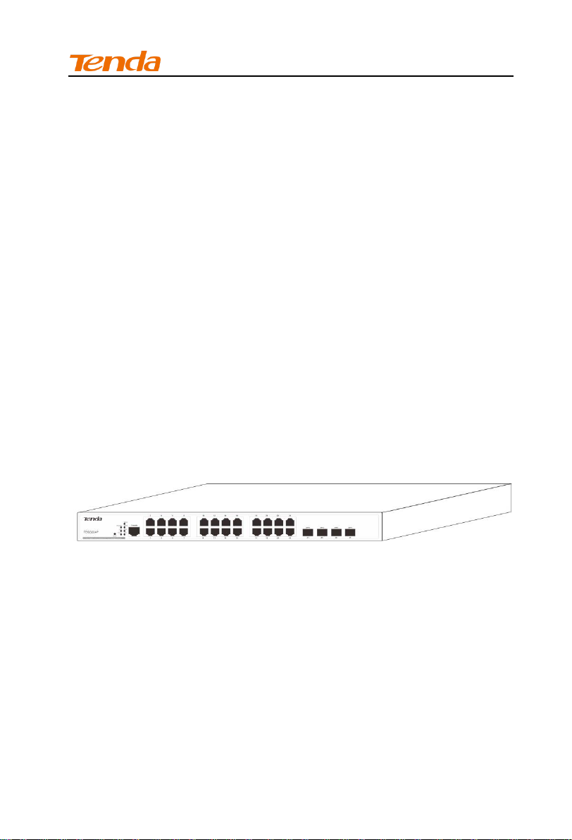
1.1 Overview
This device, a 24-port Smart Gigabit PoE Switch, provides 24
10/100/1000Mbps auto-negotiation RJ-45 ports, 4 1000Mbps
Combo (copper/fiber) ports and one Console port. All its RJ45 ports
support PoE feature and it can connect up 24 devices (15.4W)
based on IEEE 802.3af or up to 12 IEEE 802.3at devices (30W). In
addition, it supports VLAN, QoS, DHCP, IGMP snooping, ACL, STP,
RSTP, MSTP, port mirroring and other features. Aiming at solving
the safety problems in LAN, it provides management VLAN, ARP
attack defense, worm attack defense, DoS attack defense, MAC
attack defense, IP+MAC+PORT+VLAN Bind, MAC filter and other
safety settings through visual WEB interface operations. With high
performance and low cost, it is ideal for hotels and enterprises.
1.2 Physical Description
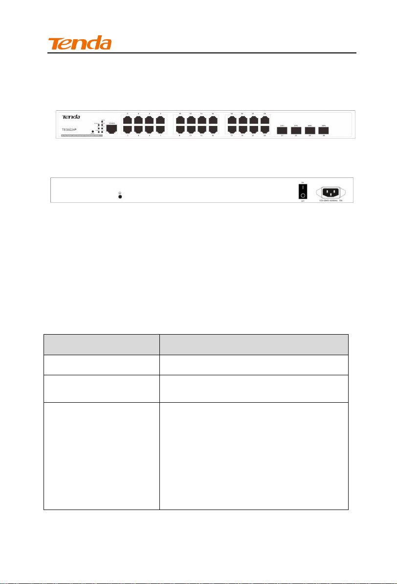
1.2.1 Front Panel
The front panel contains the following:
24 RJ-45 connectors for 10/100/1000Mbps Ethernet switching
ports;
Four SFP ports;
One Console interface;
Reset button to restart the device;
Port LEDS;
1
Page 8
Install Guide
Item
Specification
Input Voltage
176 - 264VAC 50/60Hz 6A
Power Consumption
15W(no load);
390W(full load);
PoE
24 10/100/1000Mbps auto-sensing
RJ-45 ports supporting PoE feature,
and every single port’s maximum output
can be 30W;
It supports static or dynamic power
allocation and can connect up 24
devices (15.4W) based on IEEE
802.3af or up to 12 IEEE 802.3at
devices (30W);
• System LEDs.
1.2.2 Back Panel
A grounding stud for lightning protection;
A 176-264VAC 50/60 Hz 6A universal input, which is a standard
AC power receptacle for accommodating the supplied power
cord;
A power switch for opening and cutting off power supply.
1.3 Specifications
1.3.1 Hardware Specification
2
Page 9

Install Guide
Interface
24 RJ-45 10/100/1000 auto-sensing
Giga switching ports;
4 1000Mbps SFP ports;
Management Interface
One Console port
Operating
Temperature
0℃ - 40℃
Storage Temperature
-40℃ - 70℃
Operating Humidity
10% - 90% RH, non-condensing
Storage Humidity
5% - 90% RH, non-condensing
Safety
UL 60950-1
CAN/CSAC22.2 No 60950-1
IEC 60950-1
EN 60950-1/A11
AS/NZS 60950-1
EN 60825-1
EN 60825-2
EMC
EN 55024;1998+A1:2001+A2:2003
EN 55022:2006
ICES-003:2004
EN 61000-3-2:2000+A1:2001+A2:2005
EN 61000-3-3:1995+A1:2001+A2:2005
AS/NZS CISPR 22:2004
FCC PART 15:2005
ETSI EN 300 386 V1.3.3:2005
MTBF
> 100,000h
Dimension
440mm * 284mm * 44mm
Weight
< 7.5kg
3
Page 10

Install Guide
Features
Specification
Switch Volume
(Full-duplex)
56Gbps
Packet Forwarding
Rate
35.7Mpps
MAC Address Table
8K
VLAN
1. VLAN distribution based on ports. Up to
24 can
2. beconfigured;
3. IEEE 802.1Q VLAN. Up to 128 can be
configured;
4. Protocol VLAN. Up to 16 can be
configured;
5. MAC VLAN. Up to 64 can be
configured;
6. 5. Voice VLAN;
DHCP
DHCP Snooping, DHCP Relay, and
DHCP Client
Multicast
1. IGMP Snooping V1/V2;
2. Up to 128 can be configured;
3. 3. Fast leave;
Broadcast Storm
Constrain
1. Broadcast storm constrain based on
ports;
2. Multicast storm constrain based on
ports;
3. 3. Unknown unicast storm constrain
based on ports;
1.3.2 Software Specification
4
Page 11

Install Guide
STP
1. IEEE 802.1d STP;
2. IEEE 802.1w fast STP;
3. IEEE 802.1s multiple-STP protocol. In
MSTP mode, up to 16 STP instances
can be configured;
4. Edge port;
5. P2P port;
6. 6. STP BPDU packets statistics;
ACL
1. MAC ACL. Up to 100 entries can be
configured;
2. IPv4 ACL. Up to 100 entries can be
configured;
3. 3. Time range limit;
Safety
1. ARP attack defense, worm attack
defense, DoS attack defense and
MAC attack defense;
2. User grading management and SSL
certification;
3. Management VLAN;
4. IP+MAC+PORT+VLAN Bind. Up to 200
entries can be configured;
5. interface isolation;
MAC Filter
1. Unicast MAC filter;
1. 2. Up to 1000 entries can be
configured;
QoS
1. 802.1P port trust mode;
2. IP DSCP port trust mode;
3. Bandwidth control;
2. 4. Up to 4-queue QoS mapping;
Certification
1. IEEE 802.1X based on ports;
2. IEEE 802.1X based on MAC;
3. 3. Up to 256 MAC can be certificated;
Upgrade
TFTP(Trivial File Transfer Protocol)
5
Page 12

Install Guide
Management
1. Telnet configuration;
2. Console interface configuration;
3. SNMP (Simple Network Management
Protocol);
4. 4. WEB;
PoE
1. IEEE 802.3at and IEEE 802.3af;
2. Maximum power consumption: 385W;
Maintenance
Ping\Tracert\Cable check-up;
Item
Description
Processor
32 bits CPU(200MHz)
Flash
16MB
Memory
DDR 64MB
LED/Button/I
nterface
Description
POWER
Device LEDs
SYS
System LEDs
SFP 1~4
1000Mbps SFP LEDs
RJ-45 1~24
RJ-45 auto-sensing 10/100/1000M LEDs
RESET
Pressing it for over 5 seconds to restore default
factory settings
1.3.3 Processor and Memory
1.3.4 Interface
6
Page 13

Install Guide
Console
Interface
Connecting manager PC or other terminal
devices’ Consoles to this device’s Console
interface to manage and configure the switch.
Power
Interface
AC power interface
Power Switch
Open and cut off power supply
LED
Number
Color
Status
Description
POWER
1
Green
Off
Improper connection to
power supply.
Solid
Proper connection to
power supply.
SYS
1
Green
Blinking
System is functioning
properly.
Solid
System is functioning
improperly.
Off
System is functioning
improperly.
PoE-MAX
1
Green
Solid
Reaching max power
budget (354.2W) and no
more power available for
another new PD
Off
Power available for
additional PDs.
Link/Act
1-24
24
Orange
Off
An invalid link is
established.
1.4 Device Hardware Interfaces
1.4.1 LEDs
The following table describes the port LED designations.
7
Page 14

Install Guide
LED
Number
Color
Status
Description
Solid
A valid link is established.
Blinking
Transmitting packet.
PoE 1-24
24
Green
Off
The PoE powered device
(PD) is connected and the
port is supplying power
successfully.
Solid
No PoE-powered device
(PD) connected.
SFP1 -
SFP4
4
Green
Solid
Packet transmission or a
valid link is established on
the port.
Off
An invalid link is
established on the port.
1.4.2 Interfaces
1.4.2.1 Console Interface
This switch, with a RS232 asynchronous console port, can be used
for connecting PCs to test, configure, maintain and manage the
system. The console cable is an 8-core cable. One end of the
RJ-45 plug is used to connected to the Console port on the switch;
while the other end of the DB-9 plug, connected to 9-core console
outlet.
8
Page 15

Install Guide
RJ-45
Signal
Direction
DB-9
3
TXD ← 3
5
GND - 5
6
RXD → 2
Speed Rate
Working Mode
10Mbps (auto-sensing)
Half/Full duplex
auto-negotiation
100Mbps (auto-sensing)
Half/Full duplex
auto-negotiation
1000Mbps (auto-sensing)
Full duplex auto-negotiation
Console Cable Connection Relation:
1.4.2.2 Ethernet Interface
(1) Ethernet interface overview
This device has 24 RJ-45 10/100/1000M auto sensing Gigabit
Ethernet switching ports and 4 1000M SFP fiber ports.
Speed rate and working mode in RJ-45 port mode:
Note:
SFP fiber ports can only work in full-duplex auto-negotiation
mode.
(2) RJ-45 Connector
The RJ-45 physical connector, adopting CAT5 cable, is used for
connecting 10/100/1000Mbps auto-sensing RJ-45 ports as shown
below:
9
Page 16

Install Guide
(3) SFP Connector
SFP connector, mainly for detachable connection between optical
channels, is very convenient for the test and maintenance of the
optical system. This device, with its 1000Mbps Combo (copper/fiber)
ports, supports gigabit SFP connector.
1.4.2.3 RESET Button
To restore factory defaults, press and hold the button for more than
5 seconds when switch functions correctly. When pressing it for a
while, SYS LED will be off and POWER LED is solid. The device will
restart and all LEDs will be on. When the rebooting finished, SYS
LED will be blinking, indicating restoring to default factory settings.
1.4.3 Fan
This device has three fans for heat dissipation, one for mainboard
and two for power supply to ensure stable power supply.
10
Page 17

Install Guide
1.5 Interface Serial Number
1-24: 24 10/100/1000Mbps auto-sensing RJ-45 ports
21-24/SFP1-SFP4: 1000Mbps SFP ports
Console: RS232 asynchronous serial port
11
Page 18

Install Guide
Chapter 2 Preparation
2.1 Safety Caution
To avoid any equipment damage or bodily injury caused by
improper use, read the following safety recommendations before
installing the switch. Note that the recommendations do not cover
every possible hazardous condition.
Do not place the switch on an unstable case or desk. The
switch might be severely damaged in case of a fall.
Ensure rack or operation desk is sturdy enough to support the
switch and attached accessories.
Make sure that the operating voltage is in the range labeled on
the power module of the switch.
Ensure the switch is well earthed. To avoid electrical shocks,
do not open the chassis when the switch is operating or when
the switch is just powered off.
Ensure proper ventilation of the equipment room and keep the
ventilation vents of the switch free of obstruction.
Protect it against strong current or lightning.
Ensure power supply is stable. If PoE power supply is
supported, keep the Ethernet cable within 100 meters.
2.2 Site Requirements
To keep the switch in optimum working condition and prolong its life
time, follow the instructions below for installation:
Mounting:
Desktop installations - Provide a flat table or shelf surface.
Rack-mount installations - Use a 19-inch (48.3-centimeter) EIA
standard equipment rack that is grounded and physically
secure. The rack-mount kit supplied with the switch is also
required.
12
Page 19

Install Guide
Power source:
Ensure operating power supply accords with rated input
standard.
Environmental:
Temperature - Install the switch in a dry area and well
ventilated environment. Keep the switch away from heat
sources such as direct sunlight, warm air exhausts, hot-air
vents, and heaters.
Operating humidity - The installation location should have a
maximum relative humidity of 90%, non-condensing.
Ventilation - Do not restrict airflow by covering or obstructing air
inlets on the sides of the switch. Keep at least 2 inches (5.08
centimeters) free on all sides for cooling. Be sure there is
adequate airflow in the room or wiring closet where the switch
is installed.
Operating conditions - Keep the switch at least 6 feet (1.83 m)
away from nearest source of electromagnetic noise, such as a
photocopy machine. And make sure there is more than 1.5
centimeters vertical distance free between devices that overlap
each other.
2.3 Tools
Phillips Screwdriver:P2-150mm;
Anti-electrostatic Wrist; Anti-electrostatic Gloves
Note:
The above-mentioned tools have not been provided, you need
to prepare them by yourself.
13
Page 20

Install Guide
Chapter 3 Installation
The smart Switch can be installed on a flat surface or in a standard
19-inch rack.
Note:
There is a Tenda unpacking seal on one of the screws. If you
want the local reseller maintain your device, the seal should be
kept unbroken.
3.1 Installing the Switch in a Rack
To install the switch in a rack, use the following procedures. To
perform this procedure, you need the 19-inch rack-mount kit
supplied with switch.
1. Keep the kit well-earthed and stable;
2. Insert the screws provided in the rack-mount kit through each
bracket and into the bracket mounting holes in the switch.
3. Tighten the screws with the Phillips screwdriver to secure the
switch in the rack.
14
Page 21

Install Guide
3.2 Installing the Switch on a Flat Workbench
If a standard 19-inch rack is not available, place the switch on a
clean, flat workbench. First attach the included 4 rubber feet to
corresponding position of the switch bottom to avoid potential
sliding and vibration. Ensure good ventilation proper clearance
around the switch for heat dissipation. See figure below:
Note:
1. Please keep the switch in a dry and well ventilated
environment.
2. Keep the workbench stable and well-earthed.
3. Do not restrict airflow by covering or obstructing air inlets
of the switch. Keep more than 10 centimeters free on all
sides for cooling. Be sure there is adequate airflow in the
room or wiring closet where the switch is installed.
4. Don’t put heavy articles on the Switch.
5. Make sure there is more than 1.5 centimeters vertical
distance free between devices that overlap each other.
3.3 Connecting to Protective Grounding Line
Proper connection of protective grounding line is important for
lightning protection and anti-interference. Proper connection is as
follows:
15
Page 22

Install Guide
3.3.1 With Grounding Bar
Connect the yellow-green color protective grounding cable to
binding post on the grounding bar and fix the screws.
(1) AC power input
(2) Grounding terminal connection
(3) Grounding cable protection
Note:
Firefighting hoses and building lightning rods are not the
proper options for grounding bar. The grounding cable on the
switch should be connected to the grounding bar in the IT
room.
3.3.2 Without Grounding Bar
1) With mud land nearby and allowed to bury grounding bar.
Bury an angle iron or steel pipe (≥0.5m) into the mud land. The
yellow-green color protective grounding cable should be welded to the
angle iron or steel pipe and the welding point should be embalmed.
16
Page 23

Install Guide
(1) AC power receptacle (2) Binding post
(3) Protective grounding cable (4) Earth
(5) Angle iron
2) Not allowed to bury grounding bar.
If the device supports AC power supply, you can connect it to the
grounding bar through the PE line of the AC power and ensure the
PE line in the switchgear room or beside the AC power supply
transformer is well-grounded.
17
Page 24

Install Guide
(1) Power Transformer (2) Three-core Cable
(3) Protective Grounding Cable
3.4 Connecting the power cord
Step1: Connecting one end of the included power cord to the switch
and the other end to a nearby AC power outlet.
Step2: Verify the power LED on switch's front panel. An illuminated
light indicates a proper power connection.
Note:
As for the power cord, different countries have different
standards. Please determine whether to install the card slot to
fix the power cord according to the actual situation.
3.5 Connecting to Interface Cable
3.5.1 Connecting to Console Port
Follow below steps to connect the PC or terminal to the switch (The
terminal can be the emulation program with RS232 console or a PC.
Here take the PC for example):
1. Connect the DB-9 plug on the console cable to the PC;
2. Connect the RJ-45 connector to the console port on the switch
18
Page 25

Install Guide
3.5.2 Connecting to RJ-45 ports
The switch provides auto MDI/MDIX feature on each RJ45 ports.
PCs or other terminals can simply connect to any such ports of the
switch via CAT.5, CAT.5e, or UTP cables.
1. Connect one end of the Ethernet cable to the Ethernet interface
on the switch and the other end to the remote device;
2. Check PoE LED status. For LED status, please refer to 1.4.1
LEDs.(Page 7)
3.5.3 Connecting to SFP ports
The small form-factor pluggable (SFP) is a compact, hot-pluggable
transceiver used for optical signal transmission. The module bay is
a combo port, sharing a connection with an RJ-45 port. Being a
combo port, only one type of connection can be active at any given
time. For example, both copper and fiber port cannot be used at the
same time. If both connectors are plugged in at the same time, the
fiber port becomes active.
The SFP module accommodates a standard SFP module with an LC
connector.
19
Page 26

Install Guide
3.5.4 Connecting to PDs
Connect PDs (PoE powered devices, for example, 802.3at-/802.3
af-compliant AP, IP telephone or IP camera) to switch. The power
supply mode is dynamic, PoE power supply is enabled and the power
supply standard is 802.3at by default.
3.6 Checking the Installation
Before applying power perform the following:
Inspect the equipment thoroughly.
Verify that all cables are installed correctly.
Check cable routing to make sure cables are not damaged or
creating a safety hazard.
Ensure all equipment is mounted properly and securely.
20
Page 27

Install Guide
Chapter 4 Starting the Device
4.1 Configuration Preparation
4.1.1 Connecting switch to a terminal
4.1.2 Terminal Configuration
Open your PC and run the Hyper Terminal (such as the Terminal in
Windows3.1 OS and the Hyper Terminal on Windows
95/98/NT/2000/XP OS). The following operations are under
Windows XP OS.
1) Click Start>All Programs>Accessories>Communications>
Hyper Terminal and enter the new connection’s name, say Test.
21
Page 28

Install Guide
2) Select the connected console port, say COM 1(The selected
port should be the same with the actual connected console
port).
22
Page 29

Install Guide
3) Configure port settings. Bits per second: 115200, Data bits: 8,
Parity: None, Stop bits: 1, Flow control: None. (Note: Click
Restore Defaults to restore default settings.)
23
Page 30

Install Guide
4) Click OK and the following dialog box appears.
5) Configure the hyper terminal’s properties. Click File>Properties>
Settings, select VT100 in the Emulation drop-down list and click
OK.
24
Page 31

Install Guide
4.2 Starting the device
4.2.1 Checking the device
Checking the device before connecting to power source:
1) The power cord and grounding line is correctly connected.
2) The operating power supply should accord with rated input
standard.
3) The Console cable should be correctly connected and the
terminal configurations have been completed.
4.2.2 Starting Procedures
1) After connecting the device to power supply, all
indicators(POWER、SYS、PoE-MAX、PoE 1~24、Link/Act 1~
24、SFP1~4) will light up. Then the SYS LED turns off. When
the starting is completed, the SYS LED will be blinking. The
system is functioning properly.
2) Then the device will initialize memory. When the initialization is
completed, the system will read and self-extract application
files until the terminal screen prompts you to enter the
username and password as shown below.
25
Page 32

Install Guide
3) Enter the username and password (The default is admin/admin)
and press the Enter button. Then you can configure the switch.
26
Page 33

Install Guide
Item
Caption
PC
Gigabit Ethernet NIC installed
IP and Subnet
Mask
PC’s IP and the switch’s IP should be in
the same network segment.
WEB Browser
Microsoft IE 8.0 or higher
Ethernet
Cable
One CAT.5 RJ-45 cable
Chapter 5 Web Login
5.1 Preparation
5.2 Configuration Preparation
1. Launch the browser, enter http://192.168.0.1 and then press
Enter. The login page of the switch would appear as shown
below.
2. Enter the user name and password (the default values are admin),
and then click Login to log in to the switch’s configuration
interface.
27
Page 34

Install Guide
28
Page 35

Install Guide
Chapter 6 Troubleshooting
6.1 Power Supply Troubleshooting
You can know whether there’s something wrong with the power
supply system according to the POWER LED status on the front
panel. When the system is functioning properly, the POWER LED is
solid; when the POWER LED is off, please verify that:
The power cord is correctly connected and the power switch is
enabled.
Make sure power source meets switch power specification: AC
176-264V 50/60Hz.
6.2 Terminal Troubleshooting
If the system is functioning properly, the starting info will appear on
the terminal; if any fault occurs, no info or error codes will appear on
the terminal.
6.2.1 No info Displayed on the Terminal
When powering the switch, and if the terminal displays no info,
verify that:
The power cord is correctly connected and the power switch is
enabled.
The Console cable is correctly connected.
If some faults still occur, there may be something wrong with the
console cable or the port settings of the hyper terminal and you
need to check them correspondingly.
29
Page 36

Install Guide
6.2.2 Error Codes Displayed on the Terminal
If error codes are displayed on the terminal, there may be
something wrong with the port settings of the terminal. Please verify
the following settings:
Bits per second: 115200;
Data bits: 8;
Parity: None
Stop bits: 1;
Flow control: None.
Emulation: VT100
6.3 LED Troubleshooting
Link/Act LED is off:
Check the power cord connections for the switch at the switch
and the connected device.
Ensure all cables are used correctly and comply with the Ethernet
specifications (The standard length is 100m).
PoE LED is off:
Check the crimp on the connectors and make sure that the plug is
properly inserted and locked into the port at both the PoE switch
and the connecting PD device.
Ensure all cables are used correctly and comply with the Ethernet
specifications.
Ethernet specifications limit the cable length between the switch
and the attached device to 100 m (328 ft.). Make sure the cable
between switch and the attached device is within this length.
30
Page 37

Install Guide
Appendix Safety and Emission
Statement
CE Mark Warning
This is a Class A product in a domestic environment, this product
may cause radio interference, in which case the user may be
required to take adequate measures
NOTE: (1) The manufacturer is not responsible for any radio or TV
interference caused by unauthorized modifications to this
equipment. (2) To avoid unnecessary radiation interference, it is
recommended to use a shielded RJ45 cable.
FCC Statement
This equipment has been tested and found to comply with the
limits for a Class B digital device, pursuant to part 15 of the FCC
Rules. These limits are designed to pro-vide reasonable protection
against harmful interference when the equipment is operate din a
commercial environment. This equipment generates, uses, and
can radiate radiofrequency energy and, if not installed and used in
31
Page 38

Install Guide
accordance with the instruction manual, may cause harmful
interference to radio communications. Operation of this equipment
in a residential area is likely to cause harmful interference in which
case the user will be required to correct the interference at his own
expense.
FCC Caution: Any changes or modifications not expressly
approved by the party responsible for compliance could void the
user's authority to operate this equipment.
This device complies with part 15 of the FCC Rules.
Operation is subject to the following two conditions:
(1) This device may not cause harmful interference, and (2) this
device must accept any interference received, including
interference that may cause undesired operation. The
manufacturer is not responsible for any radio or TV interference
caused by unauthorized modifications to this equipment.
NOTE: (1) The manufacturer is not responsible for any radio or TV
interference caused by unauthorized modifications to this
equipment. (2) To avoid unnecessary radiation interference, it is
recommended to use a shielded RJ45 cable.
32
 Loading...