

Page 1

AV1000 AC Wi-Fi Powerline Extender Kit
Model: PH10
User Guide
1
Page 2

Copyright Statement
© 2018 Shenzhen Tenda Technology Co., Ltd. All rights reserved.
is a registered trademark legally held by Shenzhen Tenda Technology Co., Ltd.
Other brand and product names mentioned herein are trademarks or registered trademarks of
their respective holders. Copyright of the whole product as integration, including its accessories
and software, belongs to Shenzhen Tenda Technology Co., Ltd. No part of this publication can be
reproduced, transmitted, transcribed, stored in a retrieval system, or translated into any language
in any form or by any means without the prior written permission of Shenzhen Tenda Technology
Co., Ltd.
Disclaimer
Pictures, images and product specifications herein are for references only. To improve internal
design, operational function, and/or reliability, Tenda reserves the right to make changes to the
products without obligation to notify any person or organization of such revisions or changes.
Tenda does not assume any liability that may occur due to the use or application of the product
described herein. Every effort has been made in the preparation of this document to ensure
accuracy of the contents, but all statements, information and recommendations in this document
do not constitute a warranty of any kind, express or implied.
i
Page 3
Item
Presentation
Example
Cascading menus
>
System > Live Users
Parameter and value
Bold
Set User Name to Tom.
Variable
Italic
Format: XX:XX:XX:XX:XX:XX
UI control
Bold
On the Policy page, click the OK button.
Message
“ ”
The “Success” message appears.
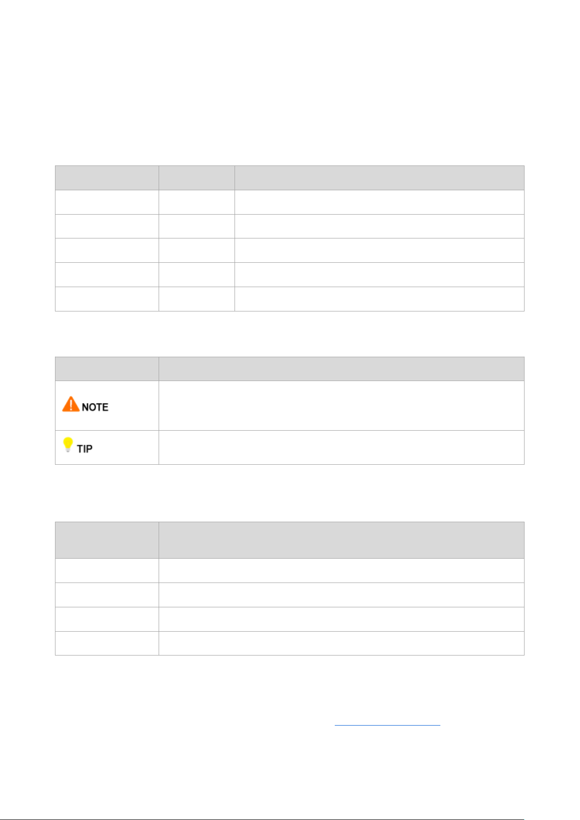
Symbol
Meaning
This format is used to highlight information of importance or special interest.
Ignoring this type of note may result in ineffective configurations, loss of data or
damage to device.
This format is used to highlight a procedure that will save time or resources.
Acronym or
Abbreviation
Full Spelling
ISP
Internet Service Provider
IPTV
Internet Protocol Television
PLC
Powerline Communication
STB
Set Top Box
Preface
Thank you for choosing Tenda! Please read this user guide before you start with PH10.
Conventions
The typographical elements that may be found in this document are defined as follows.
The symbols that may be found in this document are defined as follows.
Acronyms and Abbreviations
Additional Information
For more information, search this product model on our website at http://www.tendacn.com.
ii
Page 4

Hotline
USA hotline: 1-800-570-5892
Email
support@tenda.com.cn
Canada hotline: 1-888-998-8966
HongKong Hotline: 00852-81931998
Website
http://www.tendacn.com
Skype
tendasz
Technical Support
If you need more help, contact us by any of the following means. We will be glad to assist you as soon as
possible.
iii
Page 5

Contents
1 Introduction .............................................................................................................................................. 1
1.1 Overview ........................................................................................................................................................... 1
1.2 Features ............................................................................................................................................................ 1
1.3 LED Indicators, Port and Button ......................................................................................................................... 2
2 Hardware Installation ................................................................................................................................ 3
2.1 Installation Instruction ....................................................................................................................................... 3
2.2 Plug and Play ..................................................................................................................................................... 4
2.3 WiFi Clone (Optional) ........................................................................................................................................ 5
3 Pair the Devices......................................................................................................................................... 7
3.1 Setting up a Secure Powerline Network. ............................................................................................................. 7
3.2 Adding More Powerline Adapters to a Secure Powerline Network ...................................................................... 7
4 Configuring via Web UI .............................................................................................................................. 8
4.1 Login ................................................................................................................................................................. 8
4.2 Internet Status ................................................................................................................................................... 9
4.3 Wi-Fi ............................................................................................................................................................... 13
4.4 Guest Network ................................................................................................................................................ 17
4.5 Powerline ........................................................................................................................................................ 18
4.6 System Settings ............................................................................................................................................... 19
Appendix ........................................................................................................................................................ 25
FAQ ....................................................................................................................................................................... 25
iv
Page 6
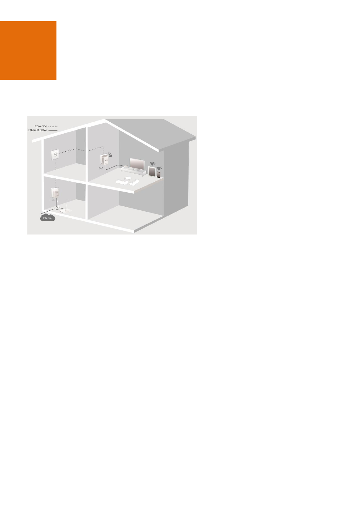
1 Introduction
1.1 Overview
AV1000 AC Wi-Fi Powerline Extender Kit
extends 650 Mbps dual band WiFi to any room
in your house using existing electrical wiring.
With 1000 Mbps Homeplug AV2 powerline
technology and gigabit Etherner port, PH10
can offer better HD/UHD IPTV and online
gaming experiences.
1.2 Features
Extending WiFi using your home's existing electrical wiring
Up to 1000 Mbps powerline transmission speed
AC650 dual band WiFi technology
Gigabit Ethernet port for wired device
Compliant with HomePlug AV, HomePlug AV2 and IEEE 1901 standards
Wi-Fi Clone for copying WiFi configuration of your router using one button
1
Page 7
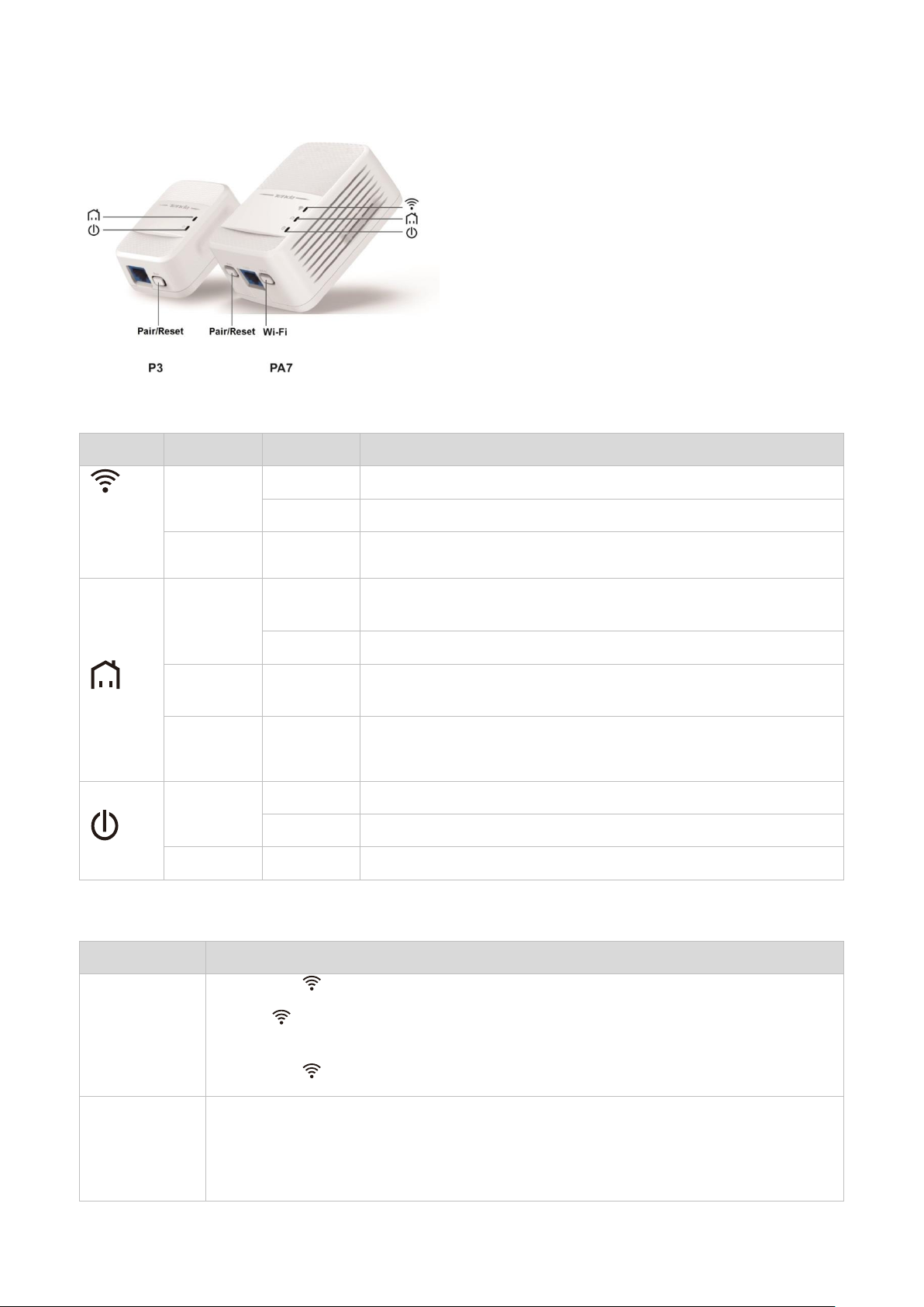
LED
Color
Status
Description
*Available
only on
PA7
Green
Solid on
The WiFi is enabled.
Blinking
The device is performing WiFi cloning.
/
Off
The WiFi is disabled.
Green
Solid on
The device is connected to a powerline network, and in good
condition.
Blinking
The device is pairing with another powerline device.
Red
Solid on
The powerline network connection is poor. Try changing another wall
receptacle until the light turns green.
/
Off
The device fails to pair with another powerline device.
The device works in power saving mode.
Green
Solid on
The device is powered on, and works properly.
Blinking
The device works in power saving mode.
/
Off
The device is not powered on, or cannot be started.
Button
Description
Wi-Fi
*Available only
on PA7
When the LED indicator is on, press it (within 3 seconds) to perform WiFi cloning.
If the LED indicator is off after the device is powered on for about 20 seconds, pressing
it (within 3 seconds) can enable WiFi.
When the LED indicator is on, hold it down for 6 seconds to disable WiFi.
Pair
After the device is powered on for about 20 seconds, press it (within 3 seconds) to pair with
another powerline device.
After the device is powered on for about 20 seconds, hold down this button for 6 seconds
to restore factory settings.
1.3 LED Indicators, Port and Buttons
LED Indicator
Port & Button
2
Page 8

2 Hardware Installation
2.1 Installation Instruction
To ensure optimum performance of PH10 and significantly improve the transmission capacity of the network, use
PH10 in the following environment:
Operating Temperature: 0 °C - 40°C
Operating Humidity: (10% - 90%) RH, non-condensing
Plug P3 and PA7 directly into wall receptacles.
Ensure that PA7 is vertical to the ground.
Ensure that all powerline adapters you want to add to the same network should be in the same electrical
circuit.
3
Page 9
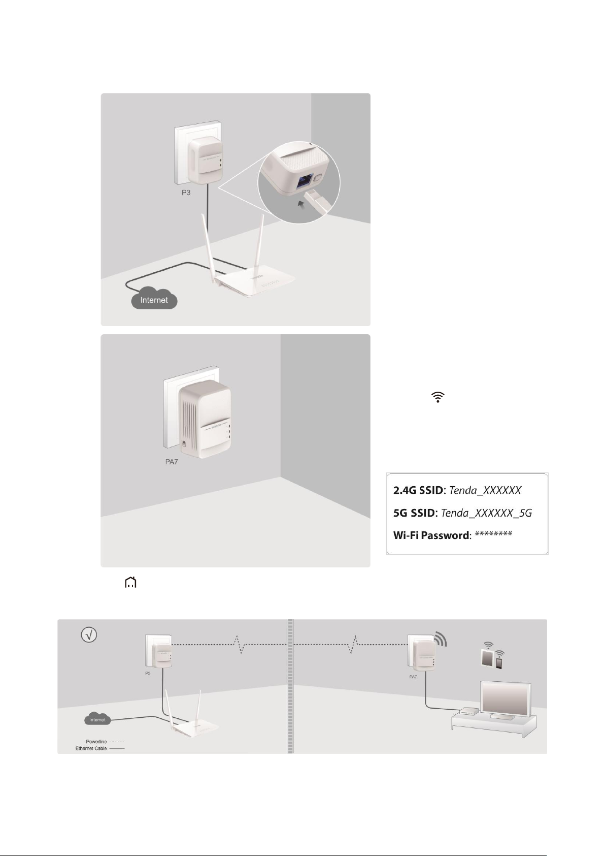
Step 1 Connect P3 to a LAN port of
your router, and plug it into a wall
receptacle nearby.
Step 2 Connect PA7 to your wired
device, such as a set-top box of a TV,
and plug it to a wall receptacle nearby.
After the LED indicator turns solid
on, connect your wireless devices to
the WiFi networks of PA7 using WiFi
names and password on the included
label in the box.
2.2 Plug and Play
Wait until the LED indicators on both P3 and PA7 turn solid on. Then your wired and wireless devices can
access the internet.
--End
4
Page 10
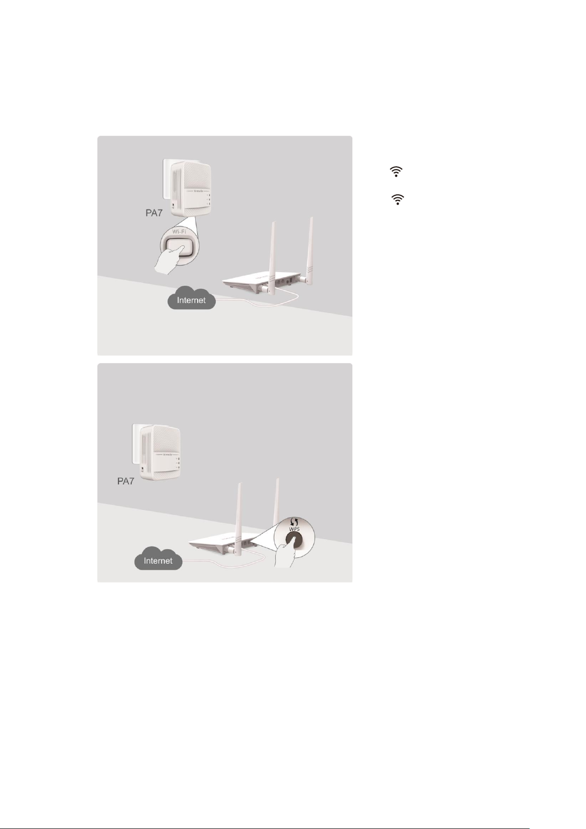
Step 1 Plug PA7 into a wall receptacle
near your wireless router, wait until
the LED lights up, then press the
Wi-Fi button on PA7.
The LED blinks.
Step 2 Press the WPS button on your
wireless router.
2.3 WiFi Clone (Optional)
If your router has no WPS button, this function is not available.
If you want to set only one WiFi signal in your house, perform the following procedure:
5
Page 11

When the LED on PA7 turns
solid on again, the WiFi name and
password of PA7 have been changed
to the same as those of your wireless
router.
Then move PA7 to a place where you
need WiFi coverage.
Now, you can connect to the WiFi
network using the WiFi name and
password of your wireless router for
internet access.
--End
If your wireless router has no WPS button, but you want to change the WiFi name and password of PA7,
refer to 4.3.1 Changing WiFi Name and Password.
6
Page 12

3 Pairing the Devices
PH10 can automatically set up a powerline network with other HomePlug AV/Homeplug AV2 compliant
powerline adapters in the same electrical circuit. If you only want specified powerline adapters to set up a secure
powerline network, or set up several different powerline networks under the same electrical circuit, you can use
the Pair button.
3.1 Setting up a Secure Powerline Network.
You can pair P3 and PA7 using the Pair button to set up a secure powerline network.
Step 1 Press the Pair button on P3, and the LED starts blinking.
Step 2 Within two minutes after step 1, press the Pair button on PA7, and the LED starts blinking.
Step 3 Wait until the LEDs on both P3 and PA7 turn solid on.
It indicates that P3 and PA7 have paired with each other successfully.
--End
3.2 Adding More Powerline Adapters to a Secure
Powerline Network
You can add more powerline adapters to an existing powerline network, only two powerline adapters can pair
with each other at a time.
Step 1 Press the Pair button on the newly added powerline adapter, and the LED starts blinking.
Step 2 Within two minutes after step 1, press the Pair button on P3 or PA7, and the LED starts
blinking.
Step 3 Wait until the LEDs on both the new added powerline adapter and P3 or PA7 turn solid on.
It indicates that the new added powerline adapter have added to the powerline network
successfully.
7
Page 13

4 Configuring via Web UI
You can manage WiFi network of PA7 and powerline network including PA7 using the web UI. Or you can
download Tenda PLC utility (and User Guide of Tenda PLC Utility if necessary) from http://www.tendacn.com to
manage PH10.
4.1 Login
Step 1 Connect your computer to PA7 using an Ethernet cable, or connect your computer or mobile device to
the WiFi network of PA7 (the default WiFi name and password are on the included label).
Step 2 Start a web browser, enter plc.tendawifi.com in the address bar, and press Enter.
Step 3 Enter the login password (admin by default), and click Login.
--End
8
Page 14

4.2 Internet Status
You can check internet status, WiFi network name and password, wireless devices connected to PA7, and
powerline devices including to the current powerline network here. Meanwhile, you can also blacklist the
unknown devices connected to the WiFi network of PA7, change WiFi name or password, and log in to the web
UI of your wireless router.
Choose Internet Status to enter this page.
4.2.1 Checking or Blacklisting the Attached Wireless Devices
If you want to check whether there are unknown devices connected to your wireless network, you can choose
Internet Status > Attached Devices to check the wireless devices list.
Click Add to add the unknown devices to blacklist if necessary. Wireless devices in blacklist cannot connect to the
WiFi network of PA7.
9
Page 15

4.2.2 Removing a Device from Blacklist
If you want a wireless device in blacklist to access the internet via the WiFi network of PA7, choose Internet
Status > Blacklist, and click Remove.
4.2.3 Changing the WiFi Settings of PA7
Choose Internet Status and click to enter the WiFi settings page. Refer to 4.3.1 Changing WiFi
Name and Password for configuration procedure.
10
Page 16

4.2.4 Logging in to the Wireless Router
You can log in to the wireless router by clicking the icon of Router on the page.
4.2.5 Powerline Devices
Choose Internet Status and click the icon of Powerline Devices . You can check the information of powerline
devices belonging to the same network as PA7.
11
Page 17

Parameter
Description
Device Name
It specifies the name of the powerline device.
MAC Address
It specifies the MAC address of the powerline device.
Tx Rate
It specifies the transmit rate of the powerline device.
Rx Rate
It specifies the receive rate of the powerline device.
Parameters Description
4.2.6 Basic Information of PA7
Choose Internet Status and click the icon of PA7 . The following page appears:
12
Page 18

Parameter
Description
Information
It displays the basic information of PA7 including system time, running time and
firmware version.
2.4G Wi-Fi Status
It displays the basic information of 2.4 GHz WiFi network.
5G Wi-Fi Status
It displays the basic information of 5 GHz WiFi network.
Parameters Description
4.3 Wi-Fi
Wi-Fi page allows you to change 2.4 GHz and 5GHz WiFi names and passwords, and set a WiFi schedule and
other wireless parameters.
Choose Wi-Fi to enter this page.
13
Page 19

Parameter
Description
WiFi Name
It specifies the wireless network name of PA7.
Security Mode
It specifies the security mode of the WiFi network of PA7. The device supports none,
WPA2-PSK and WPA/WPA2/PSK. We recommend you to keep the default settings
unless necessary.
WiFi Password
It specifies the wireless network password of PA7.
Hide
If this option is selected, wireless clients cannot search the wireless network of PA7
on their WiFi list. You must manually enter the WiFi name on your wireless clients to
connect them to the WiFi network.
4.3.1 Changing WiFi Name and Password
Step 1 Choose Wi-Fi to enter the configuration page.
Step 2 Customize your 2.4 GHz or 5 GHz WiFi name and WiFi password.
Step 3 Click OK on the bottom of this page to apply the settings.
--End
You need to reconnect your wireless device to the WiFi network of PA7 after you change the WiFi
settings.
Parameters Description
14
Page 20

4.3.2 Setting a WiFi Schedule
You can use the Wi-Fi Schedule function to specify when to disable the WiFi network.
Step 1 Choose Wi-Fi, and locate the Wi-Fi Schedule part.
Step 2 Click the button.
Step 3 Specify a period when you want to disable the WiFi, which is 11:00 pm - 06:30 am in this example.
Step 4 Select the days to which this rule applies, which are Sunday to Saturday in this example.
Step 5 Click OK on the bottom of this page to apply the settings.
--End
4.3.3 Wireless Parameters
You can try changing other wireless parameters according to the description in the following form if necessary.
15
Page 21

Parameter
Description
Mode
11b/g/n: Only 802.11b, 802.11g, and 802.11n devices are allowed to connect the WiFi.
11b/g: Only 802.11b and 802.11g devices are allowed to connect the WiFi.
11b: Only 802.11b devices are allowed to connect the WiFi.
11g: Only 802.11g devices are allowed to connect the WiFi.
11ac: Only 802.11ac devices are allowed to connect the WiFi.
11a/n/ac: Only 802.11a, 802.11n, 802.11ac devices are allowed to connect the WiFi.
Wi-Fi
Channel
Do not change the channel unless you experience wireless connection failures or slow data
transmission. If this happens, try different channels to identify the optimal channel.
Wi-Fi
Bandwidth
Auto: This is the default channel bandwidth. Keep the default value.
20: Select this bandwidth if you experience wireless connection failures.
40: Select this bandwidth to maximize the wireless throughput at 2.4 GHz.
80: Select this bandwidth to maximize the wireless throughput at 5 GHz.
Parameters Description
16
Page 22

4.4 Guest Network
A guest network is a network dedicated to guests. Clients connected to a guest network can access the internet,
but cannot access the router web UI or the non-guest network. This enables guests to access the internet and
meanwhile ensures security of the non-guest network.
You can set a WiFi name for the 2.4 GHz network and 5 GHz network each. These networks share the same
password. To distinguish between the non-guest WiFi networks of the router and the guest WiFi networks of the
router, do not adopt the same name for the networks.
Choose Guest Network to enter the configuration page.
Click the button to enable this function.
17
Page 23

Parameter
Description
Guest Network
Click this button to enable/disable the guest network.
2.4G Wi-Fi Name/5G
Wi-Fi Name
It specifies the wireless network name at 2.4 GHz/5 GHz.
Wi-Fi Password
It specifies the wireless password for 2.4 GHz wireless network and 5 GHz wireless
network.
Use 2.4G Wi-Fi name
Select this option to change 5 GHz wireless network to the same as that of 2.4 GHz
wireless network.
User Isolation
Enable: if the “Enable” option is selected, wireless devices connected to the guest
network cannot communicate with each other.
Disable: if the “Disable” option is selected, wireless devices connected to the guest
network can communicate with each other.
Parameters Description
4.5 Powerline
The Powerline page allows you to check or change powerline network parameters.
Choose Powerline to enter the configuration page.
18
Page 24

Parameter
Description
Network Name
It specifies the name of the powerline network where PA7 resides. The default
powerline network name is HomePlugAV which indicates an unencrypted powerline
network.
The powerline devices that share a same network name belong to a same
powerline network. And the powerline devices in different powerline networks
cannot communicate with each other.
Powerline devices which are compliant with HomePlugAV standard can
establish an unencrypted powerline network named HomePlugAV.
Default
Clicking Default button restores the default powerline network name.
MAC Address
It specifies the MAC address of this PA7.
Parameter
Description
Device Name
It specifies the name of the powerline device. You can change this name if there are
multiple powerline devices in the powerline network for easy recognition.
MAC Address
It specifies the MAC address of the powerline device.
Tx Rate
It specifies the transmission rate of the powerline device.
Rx Rate
It specifies the receiving rate of the powerline device.
Parameters Description
Powerline Network Settings
Powerline Device List
4.6 System Settings
4.6.1 Changing the Login Password
The Login password is used to log in to the web UI of PA7. The default one is admin.
Perform the following steps if you want to change it.
Step 1 Choose System, and move to the Login Password part.
19
Page 25

Step 2 Set Old Password to the current password admin.
Step 3 Set New Password to a new password.
Step 4 Set Confirm Password to the new password again.
Step 5 Click OK on the bottom of this page to apply the settings.
--End
4.6.2 Configuring Network Settings
If P3 is connected to a router that can access the internet properly, and PA7 has paired with P3, PA7 obtains an IP
address from the router. Then you can access the internet after connecting to PA7. In this case, you do not need
to configure the network settings of PA7.
If the router cannot assign IP addresses to its clients, you need to enable the DHCP Client function of PA7 to
assign IP addresses to its clients.
20
Page 26

Parameter
Description
Always On
It indicates that all the LED indicators of PA7 are in ordinary states.
Always Off
It indicates that all the LED indicators of PA7 are turned off.
Schedule
It indicates that all the LED indicators of PA7 are turned off in specified periods and
return to their ordinary states when the periods expire.
Turn Off During
It allows you to specify a period to turn off the LED indicators of PA7.
Turn Off On
It allows you to specify days to turn off the LED indicators of PA7.
4.6.3 LED Control
The following figure shows the available LED indicator control modes. Select one of the modes as required and
click OK.
Parameters Description
4.6.4 Time Settings
Time-based functions, such as Wi-Fi Schedule and LED Control, require correct time zone settings.
To set the time zone of PA7, perform the following steps:
Step 1 Choose System, and move to the Time Settings part.
Step 2 Select your time zone, and click OK on the bottom of this page to apply the settings.
After the settings are saved, check whether the time displayed in Current Time is correct.
21
Page 27

4.6.5 Rebooting PA7
When the parameters you set cannot take effect or PA7 cannot be used normally, please try rebooting it to solve
these problems. Note that when PA7 is rebooting, do not unplug it.
Step 1 Choose System and move to the Reboot part.
Step 2 Click Reboot.
Step 3 Click Reboot on the pop-up window.
--End
4.6.6 Resetting PA7
Hold down the Pair hardware button for 6 seconds to reset PA7, or perform the following steps to reset it:
Step 1 Choose System.
Step 2 Move to the Reset part, and click Reset.
Step 3 Click Reset on the pop-up window.
--End
You are recommended not to reset PA7 unless:
You forget the login password of the web UI of PA7.
PA7 does not work well, and you want to reconfigure it.
You cannot access the internet, and Tenda technical support recommends you to restore factory
default settings.
22
Page 28

4.6.7 Upgrading PA7
Tenda website offers the latest firmware version for PA7. Perform the following steps to upgrade PA7:
Online Upgrade:
The device is set to online upgrade by default. The device will detect whether your firmware is latest. If not, you
can update it to the latest.
Local Upgrade:
Step 1 Start a web browser, and visit www.tendacn.com.
Step 2 Enter PA7 in the search box, and download the latest firmware to your local host.
Step 3 Log in to the web UI of PA7, and choose System.
Step 4 Move to the Firmware Upgrade part, and click Upgrade.
Step 5 Select Local Upgrade.
23
Page 29

Step 6 Select the firmware you saved, and click Upgrade.
--End
4.6.8 Exporting System Logs
When encountering a problem, you can export the system logs and send them to Tenda technical support for
troubleshooting.
Step 1 Choose System.
Step 2 Move to the Export System Log part, and click Export.
--End
24
Page 30

Appendix
FAQ
Q1: The LEDs are off when both P3 and PA7 are powered on. What should I do?
A1: Try the following methods:
Verify that P3 and PA7 use a same electric meter.
Press the Pair button on P3, and its LED blinks. Within 2 minutes after pressing Pair button on P3, press
the Pair button on PA7, and its LED blinks. Wait until both LEDs turn solid on.
Reset P3 and PA7. Method: hold down the Pair/Reset button for 6 seconds to restore factory settings.
Q2: My wireless router does not support WPS, or WiFi clone fails. What should I do if I want to change the
WiFi name and password of PA7?
A2: You can log in to the web UI of PA7 to change the WiFi name and password.
Method:
① Connect your computer to PA7 wirelessly or via an Ethernet cable.
② Start a web browser, and visit http://plc.tendawifi.com.
③ Log in to the web UI with default login password admin, and go to Wi-Fi Settings page to change the WiFi
name and password.
Q3: I cannot access the internet, but the internet status on web UI of PA7 is normal. What should I do?
A3: Check whether your wireless router enables some restriction function, such as MAC address filtering,
parental control, PPPoE server, and so on.
Q4: How to reset P3 or PA7
A4: After the device is powered on for about 20 seconds, hold down the Pair button for 6 seconds. When the
LED indicator turns off, P3 or PA7 restores to factory settings successfully.
25
Page 31

CE Mark Warning
This is a Class B product. In a domestic environment, this product may cause radio interference, in which case the
user may be required to take adequate measures.
Operations in the 5.15-5.25GHz band are restricted to indoor use only.
This equipment should be installed and operated with minimum distance 20cm between the radiator & your
body.
NOTE: (1) The manufacturer is not responsible for any radio or TV interference caused by unauthorized
modifications to this equipment. (2) To avoid unnecessary radiation interference, it is recommended to use a
shielded RJ45 cable.
Declaration of Conformity
Hereby, SHENZHEN TENDA TECHNOLOGY CO. LTD. declares that the radio equipment type PA7 is in compliance
with Directive 2014/53/EU.
The full text of the EU declaration of conformity is available at the following internet address:
http://www.tendacn.com/en/service/download-cata-101.html
Operate Frequency:
2.4 GHz: EU/2400-2483.5 MHz (CH1-CH13)
5 GHz: 5150-5250 MHz
EIRP Power (Max.):
2.4 GHz: 19.3 dBm
5 GHz: 22.1 dBm
Software Version: V1.0.0.5
RECYCLING
This product bears the selective sorting symbol for Waste electrical and electronic equipment (WEEE). This
means that this product must be handled pursuant to European directive 2012/19/EU in order to be recycled or
dismantled to minimize its impact on the environment.
User has the choice to give his product to a competent recycling organization or to the retailer when he buys a
new electrical or electronic equipment.
-for PLUGGABLE EQUIPMENT,the socket-socket shall be installed near the equipment and Shall be easily
accessible.
26
Page 32

FCC Statement
This equipment has been tested and found to comply with the limits for a Class B digital device, pursuant to Part
15 of the FCC Rules. These limits are designed to provide reasonable protection against harmful interference in a
residential installation. This equipment generates, uses and can radiate radio frequency energy and, if not
installed and used in accordance with the instructions, may cause harmful interference to radio communications.
However, there is no guarantee that interference will not occur in a particular installation. If this equipment does
cause harmful interference to radio or television reception, which can be determined by turning the equipment
off and on, the user is encouraged to try to correct the interference by one or more of the following measures:
— Reorient or relocate the receiving antenna.
— Increase the separation between the equipment and receiver.
— Connect the equipment into an outlet on a circuit different from that to which the receiver is connected.
— Consult the dealer or an experienced radio/TV technician for help.
This device is restricted to be used in the indoor.
Operation is subject to the following two conditions: (1) this device may not cause harmful interference, and (2)
this device must accept any interference received, including interference that may cause undesired operation.
Radiation Exposure Statement
This device complies with FCC radiation exposure limits set forth for an uncontrolled environment and it also
complies with Part 15 of the FCC RF Rules.
This equipment should be installed and operated with minimum distance 20cm between the radiator & your
body.
Caution:
Any changes or modifications not expressly approved by the party responsible for compliance could void the
user's authority to operate this equipment.
This transmitter must not be co-located or operating in conjunction with any other antenna or transmitter.
NOTE: (1) The manufacturer is not responsible for any radio or TV interference caused by unauthorized
modifications to this equipment. (2) To avoid unnecessary radiation interference, it is recommended to use a
shielded RJ45 cable.
27
 Loading...