

Page 1

2Km Outdoor Point to Point CPE
User Guide
1
Page 2

Copyright Statement
© 2019 Shenzhen Tenda Technology Co., Ltd. All rights reserved.
is a registered trademark legally held by Shenzhen Tenda Technology Co., Ltd. Other
brand and product names mentioned herein are trademarks or registered trademarks of their
respective holders. Copyright of the whole product as integration, including its accessories and
software, belongs to Shenzhen Tenda Technology Co., Ltd. No part of this publication can be
reproduced, transmitted, transcribed, stored in a retrieval system, or translated into any language
in any form or by any means without the prior written permission of Shenzhen Tenda Technology
Co., Ltd.
Disclaimer
Pictures, images and product specifications herein are for references only. To improve internal
design, operational function, and/or reliability, Tenda reserves the right to make changes to the
products without obligation to notify any person or organization of such revisions or changes.
Tenda does not assume any liability that may occur due to the use or application of the product
described herein. Every effort has been made in the preparation of this document to ensure
accuracy of the contents, but all statements, information and recommendations in this document
do not constitute a warranty of any kind, express or implied.
i
Page 3
Item
Presentation
Example
Cascading menus
>
System > Live Users
Parameter and value
Bold
Set User Name to Tom.
Variable
Italic
Format: XX:XX:XX:XX:XX:XX
UI control
Bold
On the Policy page, click the OK button.
Message
“ ”
The “Success” message appears.
Symbol
Meaning
This format is used to highlight information of importance or special interest.
Ignoring this type of note may result in ineffective configurations, loss of data or
damage to device.
This format is used to highlight a procedure that will save time or resources.
Acronym or
Abbreviation
Full Spelling
AP
Access Point
ARP
Address Resolution Protocol
AES
Advanced Encryption Standard
CPE
Customer Premises Equipment
CCQ
Client Connection Quality
DHCP
Dynamic Host Configuration Protocol
DNS
Domain Name System
DDNS
Dynamic Domain Name Server
Preface
Thank you for choosing Tenda! Please read this user guide before you start.
Conventions
The typographical elements that may be found in this document are defined as follows.
The symbols that may be found in this document are defined as follows.
Acronyms and Abbreviations
ii
Page 4

Acronym or
Abbreviation
Full Spelling
GMT
Greenwich Mean Time
IP
Internet Protocol
ICMP
Internet Control Message Protocol
LAN
Local Area Network
MAC
Media Access Control
PoE
Power Over Ethernet
P2MP
Point-to-MultiPoint
PVID
Port-based VLAN ID
RADIUS
Remote Authentication Dial In User Service
SSID
Service Set Identifier
TCP
Transmission Control Protocol
TKIP
Temporal Key Integrity Protocol
UDP
User Datagram Protocol
VLAN
Virtual Local Area Network
WAN
Wide Area Network
WEP
Wired Equivalent Privacy
WLAN
Wireless Local Area Networks
WMM
Wi-Fi multi-media
WPA-PSK
WPA-Preshared Key
WPA
Wi-Fi Protected Access
iii
Page 5

Hotline
Global: (86) 755-27657180
Toll Free: Mon - Fri 9 am - 6 pm
(China Time Zone)
Email
support@tenda.com.cn
United States: 1-800-570-5892
Toll Free: Daily-9am to 6pm EST
Canada: 1-888-998-8966
Toll Free: Mon - Fri 9 am - 6 pm PST
Hong Kong: 00852-81931998
Toll Free: Mon - Fri 9 am - 6 pm
(China Time Zone)
Website
http://www.tendacn.com
Additional Information
For more information, search this product model on our website at http://www.tendacn.com.
Technical Support
If you need more help, contact us by any of the following means. We will be glad to assist you as
soon as possible.
iv
Page 6

Contents
1 Introduction .................................................................................................................................. 1
1.1 Overview ................................................................................................................................ 1
1.2 Getting to know your device .................................................................................................. 1
2 Quick setup ................................................................................................................................... 4
2.1 AP mode ................................................................................................................................. 4
2.2 Client mode ............................................................................................................................ 7
2.3 Example of AP mode and client mode ................................................................................. 10
2.4 Universal repeater mode ..................................................................................................... 16
2.5 WISP mode ........................................................................................................................... 22
2.6 Repeater mode ..................................................................................................................... 31
2.7 P2MP mode .......................................................................................................................... 41
2.8 Example of repeater mode and P2MP mode ....................................................................... 45
2.9 Router mode ........................................................................................................................ 52
3 Web UI ......................................................................................................................................... 56
3.1 Login ..................................................................................................................................... 56
3.2 Logout .................................................................................................................................. 58
3.3 Web UI layout ....................................................................................................................... 59
3.4 Common buttons ................................................................................................................. 59
4 Status ........................................................................................................................................... 60
4.1 System status ....................................................................................................................... 60
4.2 Wireless status ..................................................................................................................... 63
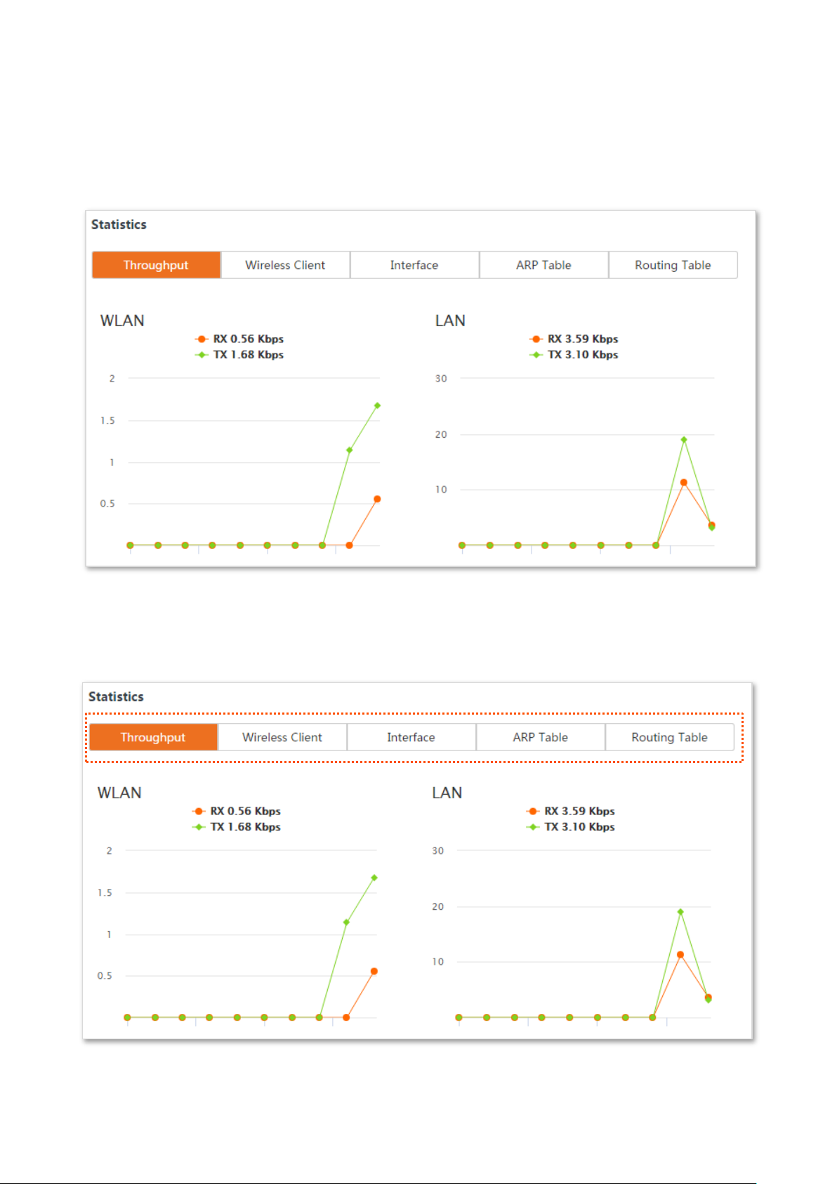
4.3 Statistics ............................................................................................................................... 65
5 Network....................................................................................................................................... 70
5.1 LAN setup ............................................................................................................................. 70
5.2 MAC clone ............................................................................................................................ 77
5.3 DHCP server ......................................................................................................................... 79
v
Page 7

5.4 DHCP client ........................................................................................................................... 81
5.5 VLAN settings ....................................................................................................................... 82
6 Wireless ....................................................................................................................................... 86
6.1 Basic ..................................................................................................................................... 86
6.2 Advanced ............................................................................................................................ 114
6.3 Access control .................................................................................................................... 118
7 Advanced ................................................................................................................................... 121
7.1 LAN rate .............................................................................................................................. 121
7.2 Diagnose ............................................................................................................................. 123
7.3 Bandwidth control .............................................................................................................. 130
7.4 Port forwarding .................................................................................................................. 133
7.5 MAC filter ........................................................................................................................... 137
7.6 Network service ................................................................................................................. 141
8 Tools .......................................................................................................................................... 159
8.1 Date & time ........................................................................................................................ 159
8.2 Maintenance ...................................................................................................................... 161
8.3 Account .............................................................................................................................. 166
8.4 System log .......................................................................................................................... 169
Appendix .......................................................................................................................................... 170
A.1 FAQ ..................................................................................................................................... 170
A.2 Default parameters ............................................................................................................ 173
vi
Page 8
LED Indicator
Status
Description
PoE/LAN
Solid on
The device is being powered properly, and no data is being
transmitted.
Blinking
Data is being transmitted over the port.
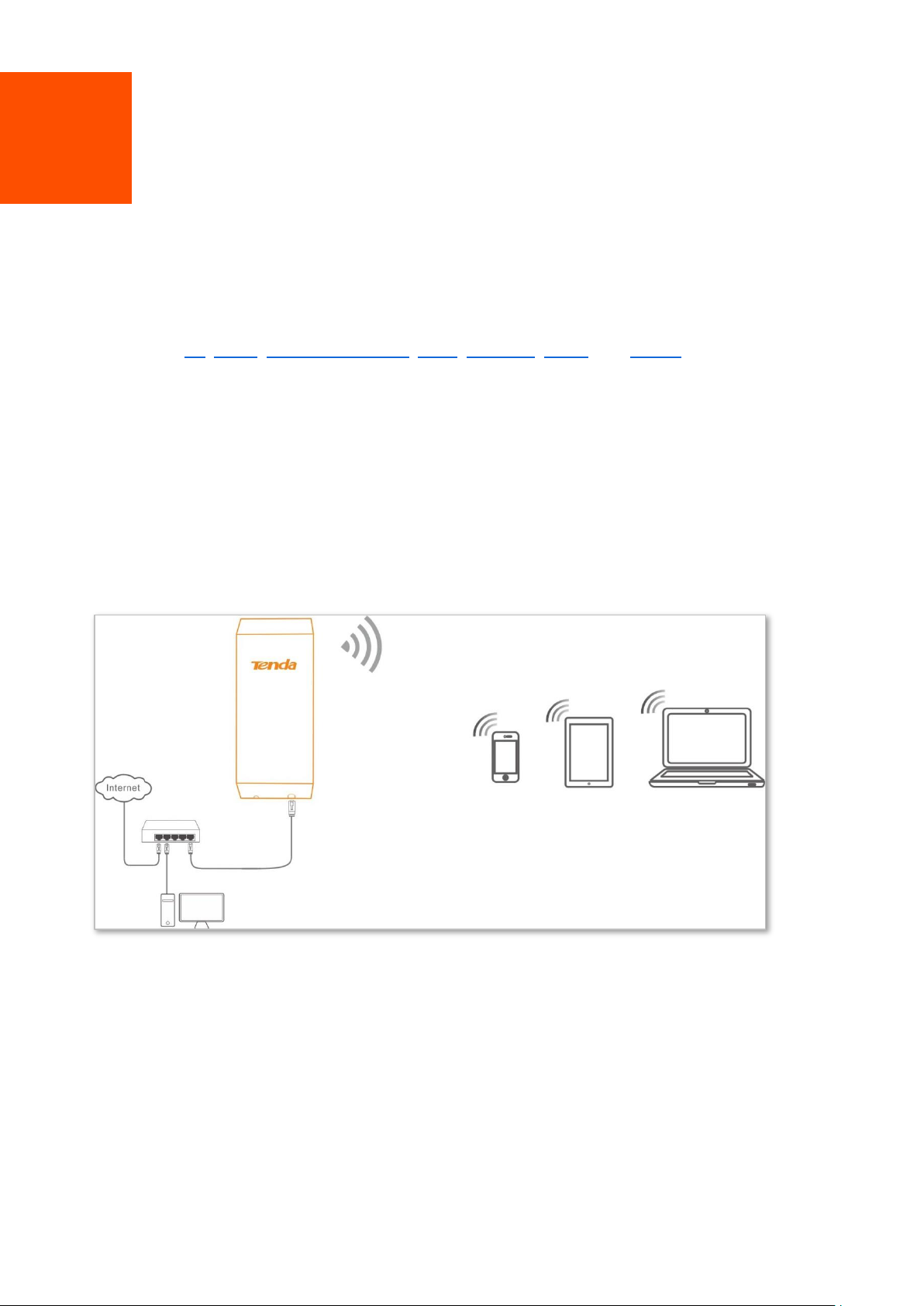
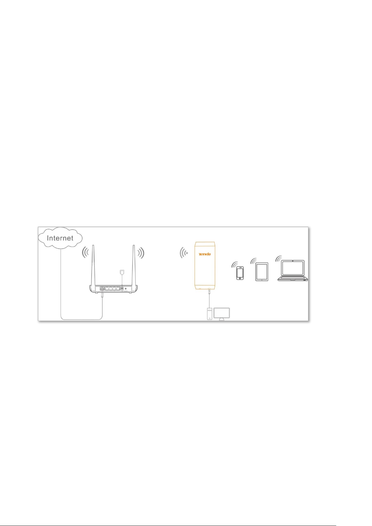
1 Introduction
1.1 Overview
The Tenda outdoor point to point CPE is dedicated for ISP and CCTV surveillance. Featured 12 dBi
directional antennas, it offers strong and stable WiFi signals and a wireless connection up to 2
kilometers. The industry grade waterproof and dustproof housing allows it to work properly even
in harsh environments. With auto-bridging technology, two CPEs can connect to each other
automatically to make setup a breeze.
1.2 Getting to know your device
LED indicators
1
Page 9
LED Indicator
Status
Description
Off
The device is not powered on.
WiFi
Solid on
The wireless function is enabled, but no data is being transmitted.
Blinking
Data is being transmitted in a wireless manner.
Off
The wireless function is disabled.
LED1, LED2, LED3
(Signal strength LED)
Solid
on/Blinking
Signal strength LED indicators. Solid on indicates the device works in
AP, P2MP, Repeater or Router mode, while blinking indicates the
device works in Client, Universal Repeater or WISP mode. The
corresponding LED indicator lights up when the received signal
strength reaches the threshold of the corresponding LED indicator
which is set on the Wireless > Advanced page. The default threshold
for LED1, LED2, and LED3 are -90 dBm, -80 dBm, and -70 dBm
respectively.
LED1, LED2 and LED3 are solid on/blinking: Good signal
LED1 and LED2 are sold on/blinking, and LED3 is off: Fair signal
LED1 is solid on/blinking, and LED2 and LED3 are off: Weak signal.
Please adjust the direction or location of your devices.
Off
The received signal does not reach the minimum threshold of the
signal strength LED indicator.
⑥①②
③
⑤
④
Button and ports
2
Page 10
ID
Port/Button
Description
①
DC
Power jack. Use the included power adapter to connect this jack to a power
source for power supply.
②
Reset
Reset Button. After the device is powered on for 1 minute, hold down this
button for about 8 seconds. When all the LED indicators on the device light
up, the device is restored factory settings.
③
PoE/LAN
This port is used to supply power or transmit data.
To power on the device using PoE, connect this port to the PoE port of the
included PoE injector.
If the device is powered on using a DC power adapter, this port functions as
a LAN port, and can be connected to a switch.
④ / Ethernet cable inlet.
⑤ / Power cord inlet.
⑥ / Press this button to uncover the device.
①
②
③ ④ ⑤
⑥
Product label
①Product name of the device
②Product model of the device
③Default login IP address of the device
④Default login user name of the device
⑤Default login password of the device
⑥Power input standard of the device
3
Page 11
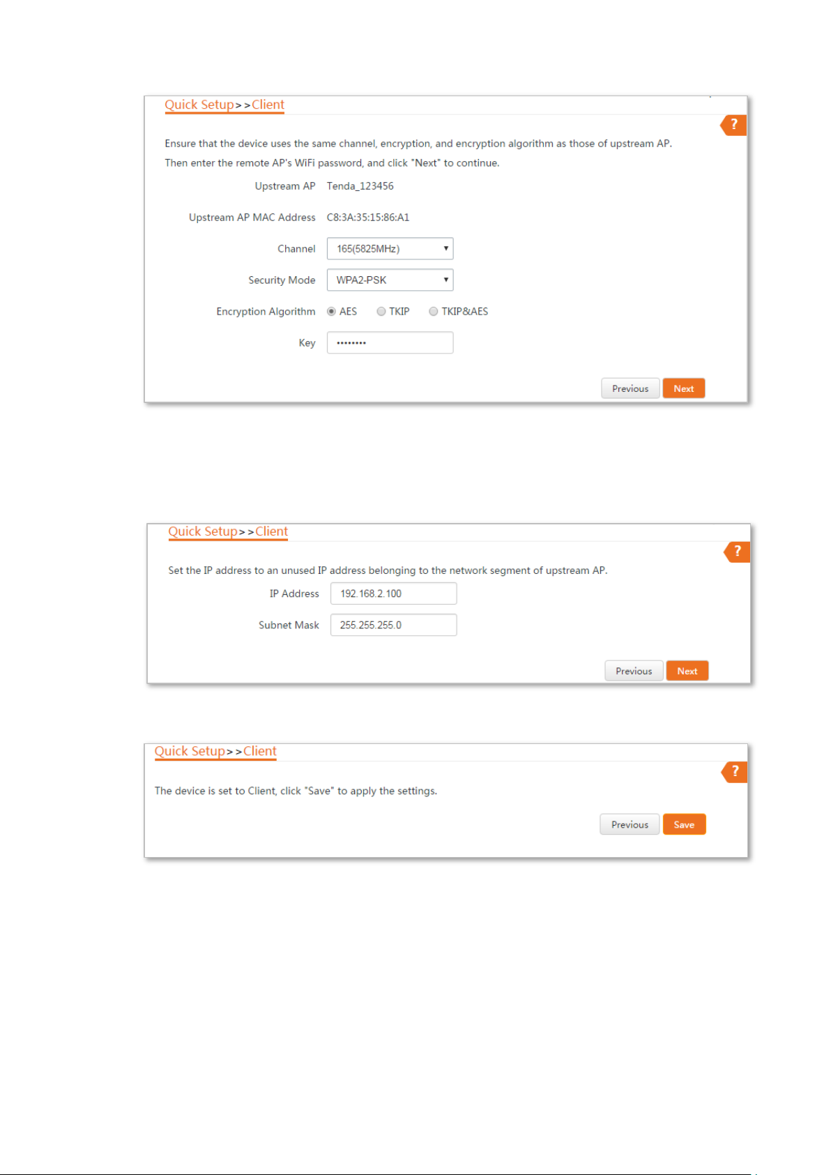
AP mode
Router
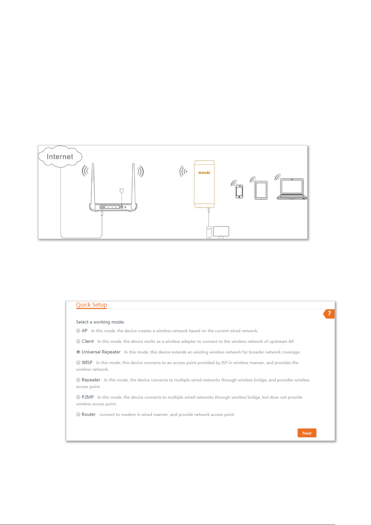
2 Quick setup
This module enables you to quickly configure the device or change the working mode of the device
to deploy your wireless network.
O2 supports AP, Client, Universal Repeater, WISP, Repeater, P2MP, and Router modes.
2.1 AP mode
In AP mode, this device connects to a wired network, and provides a wireless network for wireless
clients.
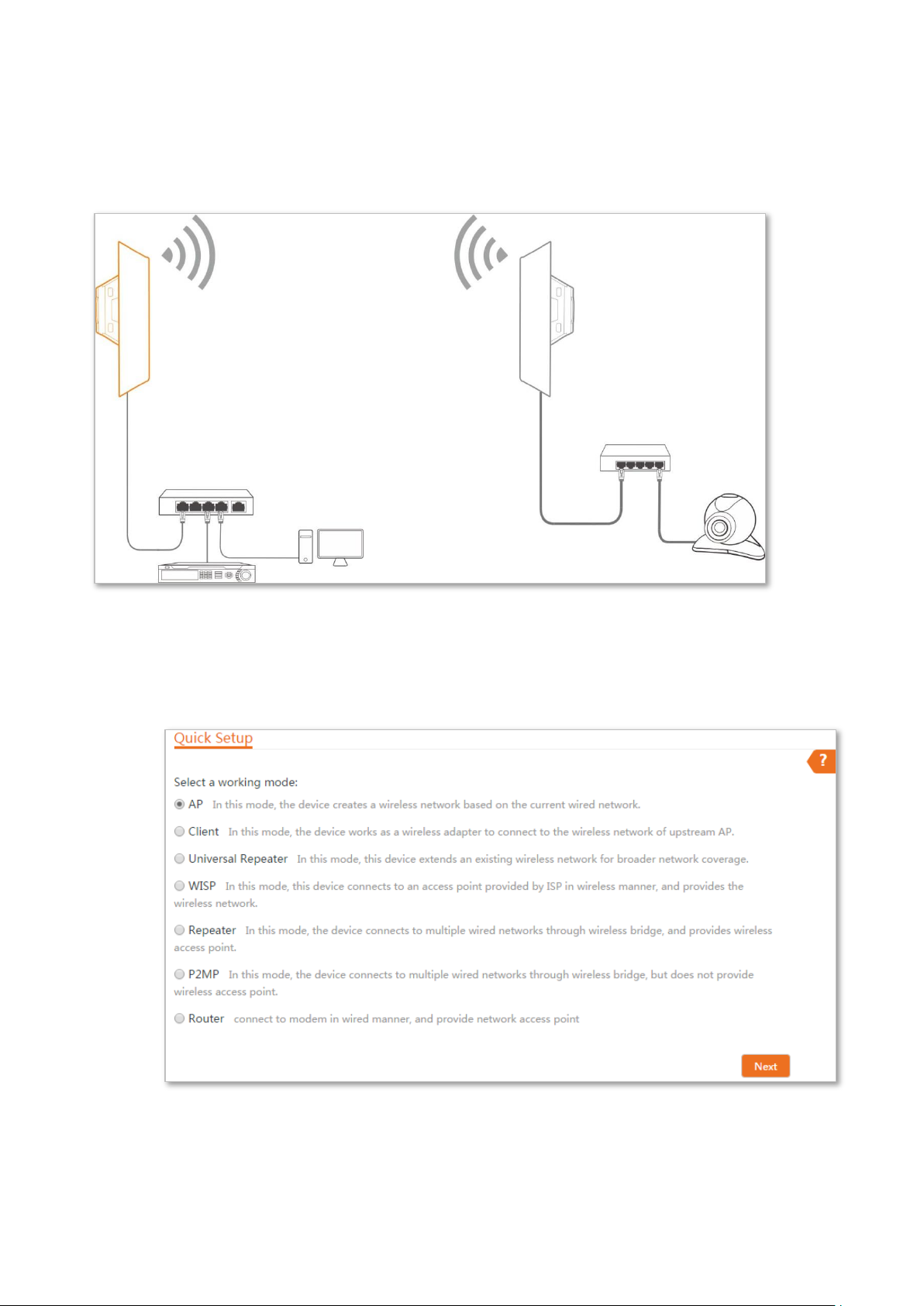
Application scenario 1
Network requirement: You want to transform your wired network to a wireless one for your
wireless devices to access the internet.
4
Page 12
AP mode
Client mode
Switch
NVR
Computer
Switch
IP Camera
Application scenario 2
Network requirement: You want to establish a CCTV surveillance network, and use the CPE to
connect to the NVR.
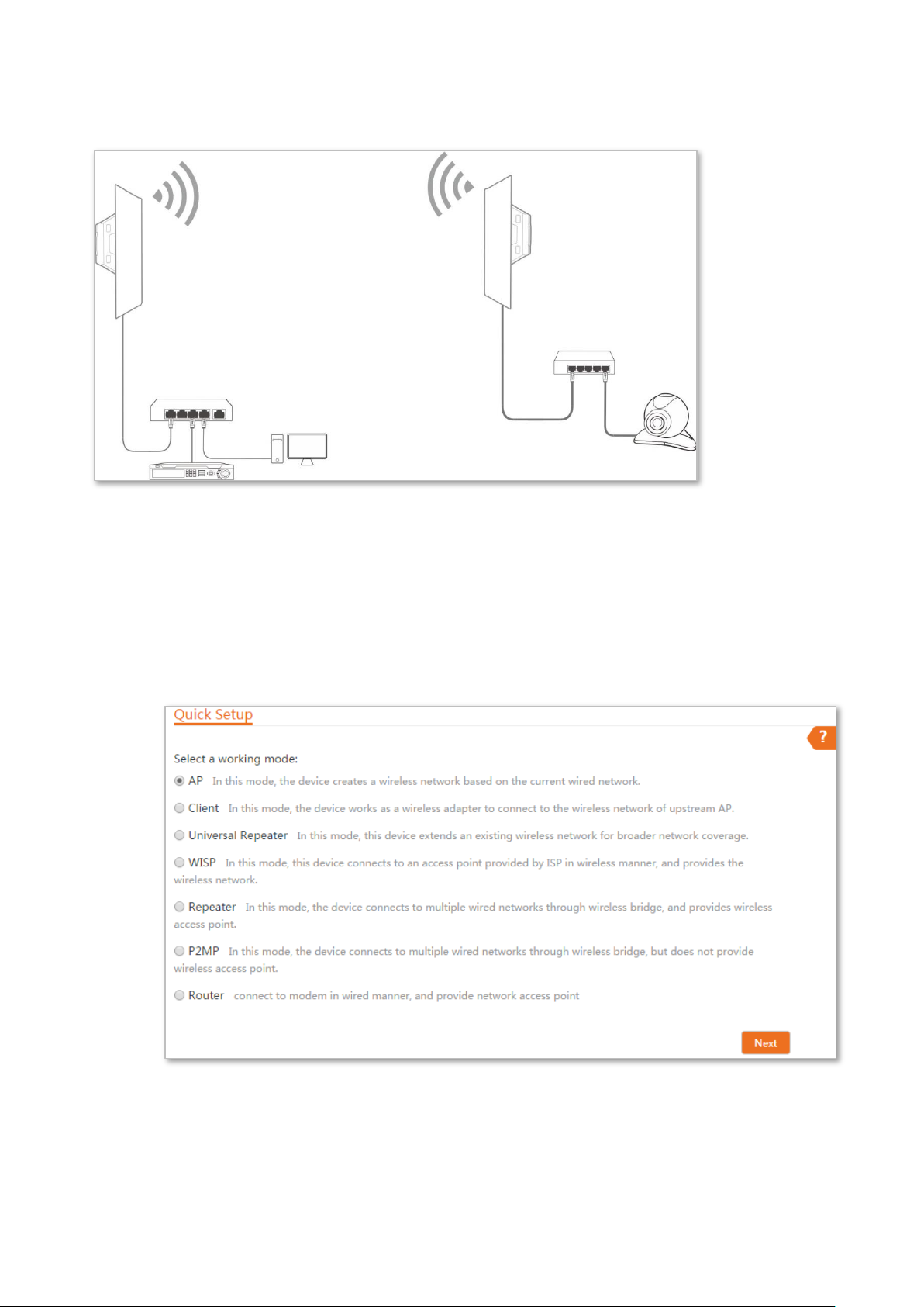
Configuration procedure of setting AP mode
Step 1 Log in to the web UI of the CPE and choose Quick Setup to enter the configuration page.
Step 2 Select AP mode and click Next.
Step 3 Set an SSID, Security Mode (WPA2-PSK is recommended) and Key, and click Next.
5
Page 13
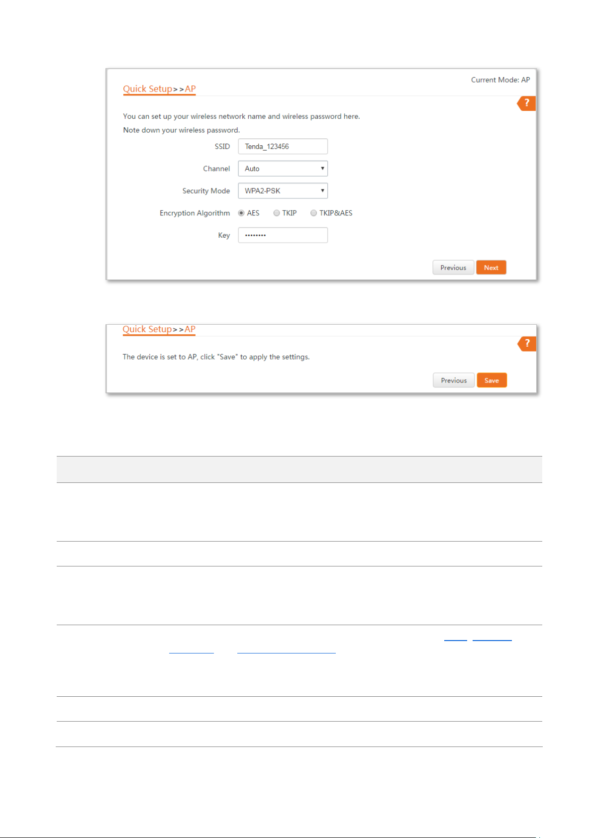
Name
Description
Working modes
It specifies the working mode of this device.
AP mode: in this mode, the device creates a wireless network based on the current
wired network.
SSID
It specifies the wireless network name of this device.
Channel
It specifies the operating channel of this device.
Auto: It indicates that the device automatically adjusts its operating channel according
to the ambient environment.
Security Mode
It specifies the security mode of the wireless network, including: None, WPA-PSK,
WPA2-PSK, and Mixed WPA/WPA2-PSK.
Clicking the hyperlink navigates you to the elaborated description of the
corresponding security mode.
Encryption Algorithm
It specifies the encryption method of the wireless network.
Key
It specifies the WiFi password of the wireless network.
Step 4 Click Save, and wait until the device reboots automatically to activate the settings.
----End
Parameters description
6
Page 14
AP mode
Client mode
Switch
Switch
IP camera
Computer
NVR
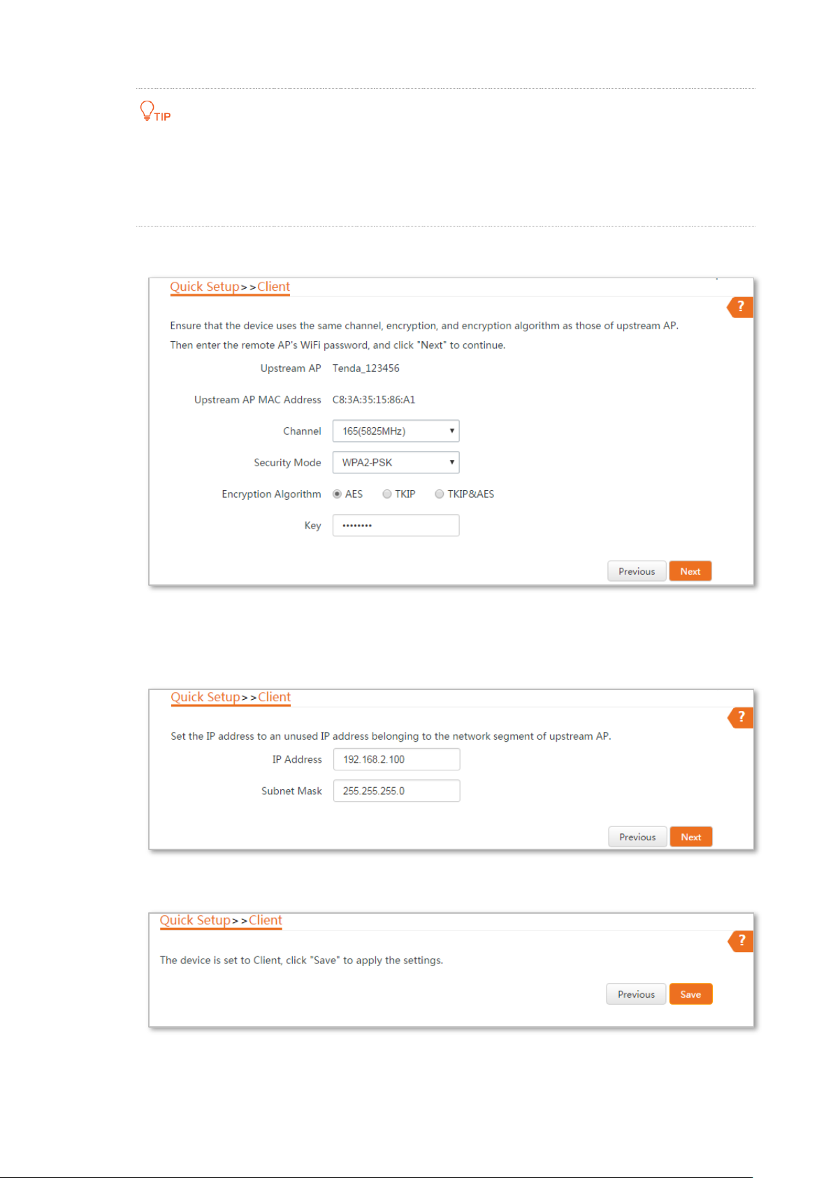
2.2 Client mode
In Client mode, this device servers as a wireless adapter, and connects to a wireless network of
upstream AP.
Application scenario
Network requirement: you want to establish a CCTV surveillance network, and use the CPE to
connect to IP cameras.
Configuration procedure of setting Client mode
Step 1 Log in to the web UI of CPE and choose Quick Setup to enter the configuration page.
Step 2 Select Client, and click Next.
7
Page 15
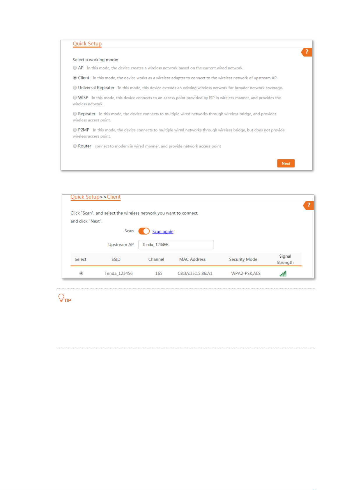
Step 3 Select the SSID of the peer device and click Next.
If you cannot find any SSID from the list, choose Wireless > Basic and enable the wireless function.
Then try again.
If you cannot find the SSID of CPE1 from the list, adjust the direction of CPE2, and move it close to
the CPE1.
Step 4 Enter the WiFi password you set on the peer device in the Key text box, and click Next.
8
Page 16
Step 5 Set the IP address to an unused IP address belonging to the same network segment as
that of the peer device. For example, if the IP address of the peer device is 192.168.2.1,
you can set the IP address of the device to 192.168.2.X (X ranges from 2 to 254). Then
click Next.
Step 6 Click Save, and wait until the device reboots to activate the settings.
----End
When LED1, LED2, and LED3 of the peer device are solid on, and LED1, LED2, and LED3 of the CPE
are blinking, the bridging succeeds.
9
Page 17

Name
Description
Working modes
It specifies the working mode of this device.
Client mode: in this mode, the device works as a wireless adapter to connect to the
wireless network of upstream AP, and does not provide wireless access point.
Upstream AP
It specifies the wireless network name (SSID) of the upstream AP.
Channel
It specifies the operating channel of the WiFi network to be bridged. It will be
automatically populated when you select an SSID to bridge.
Security Mode
It specifies the security mode of the WiFi network to be bridged. It will be automatically
populated when you select an SSID to bridge. If the WiFi network to be bridged has a
WiFi password, you need to enter the password manually.
If you cannot find any SSID from the list, choose Wireless > Basic and enable the wireless function.
Then try again.
If you cannot find the SSID of CPE1 from the list, adjust the direction of CPE2, and move it close to
the CPE1
Parameters description
2.3 Example of AP mode and client mode
Network requirement
You want to use two CPEs to establish a CCTV surveillance network.
Solution
− Set CPE1 to the AP mode, and connected it to the NVR.
− Set CPE2 to the Client mode, and connected it to IP cameras.
10
Page 18
Switch
Computer
CPE1: AP mode
CPE2: Client mode
Switch
IP camera
Network topology
Configuration procedure
Step 1 Set up CPE1.
1. Log in to the web UI of CPE1, and choose Quick Setup to enter the configuration page.
2. Select AP mode and click Next.
3. Set an SSID, which is Tenda_123456 in this example, Security Mode (WPA2-PSK is
recommended) and Key, and click Next.
11
Page 19
4. Click Save, and wait until the device reboots automatically to activate the settings.
Step 2 Set up CPE2.
1. Log in to the web UI of CPE2 and choose Quick Setup to enter the configuration page.
2. Select Client, and click Next.
3. Select the SSID of the CPE1, which is Tenda_123456 in this example, and click Next.
12
Page 20

13
Page 21
If you cannot find any SSID from the list, choose Wireless > Basic and enable the wireless function.
Then try again.
If you cannot find the SSID of CPE1 from the list, adjust the direction of CPE2, and move it close to
the CPE1.
4. Enter the WiFi password you set on CPE1 in the Key text box, and click Next.
5. Set the IP address to an unused IP address belonging to the same network segment as
that of CPE1. For example, if the IP address of CPE1 is 192.168.2.1, you can set the IP
address of the device to 192.168.2.X (X ranges from 2 to 254). Then click Next.
6. Click Save, and wait until the device reboots to activate the settings.
----End
14
Page 22

When LED1, LED2, and LED3 of CPE1 are solid on, and LED1, LED2, and LED3 of CPE2 are
blinking, the bridging succeeds.
You can check the SSID and key of CPE2 by choosing Wireless > Basic after logging in to
the web UI.
Verification
Surveillance videos can be seen on the computer in the side of CPE1.
15
Page 23
Universal repeater mode
Router
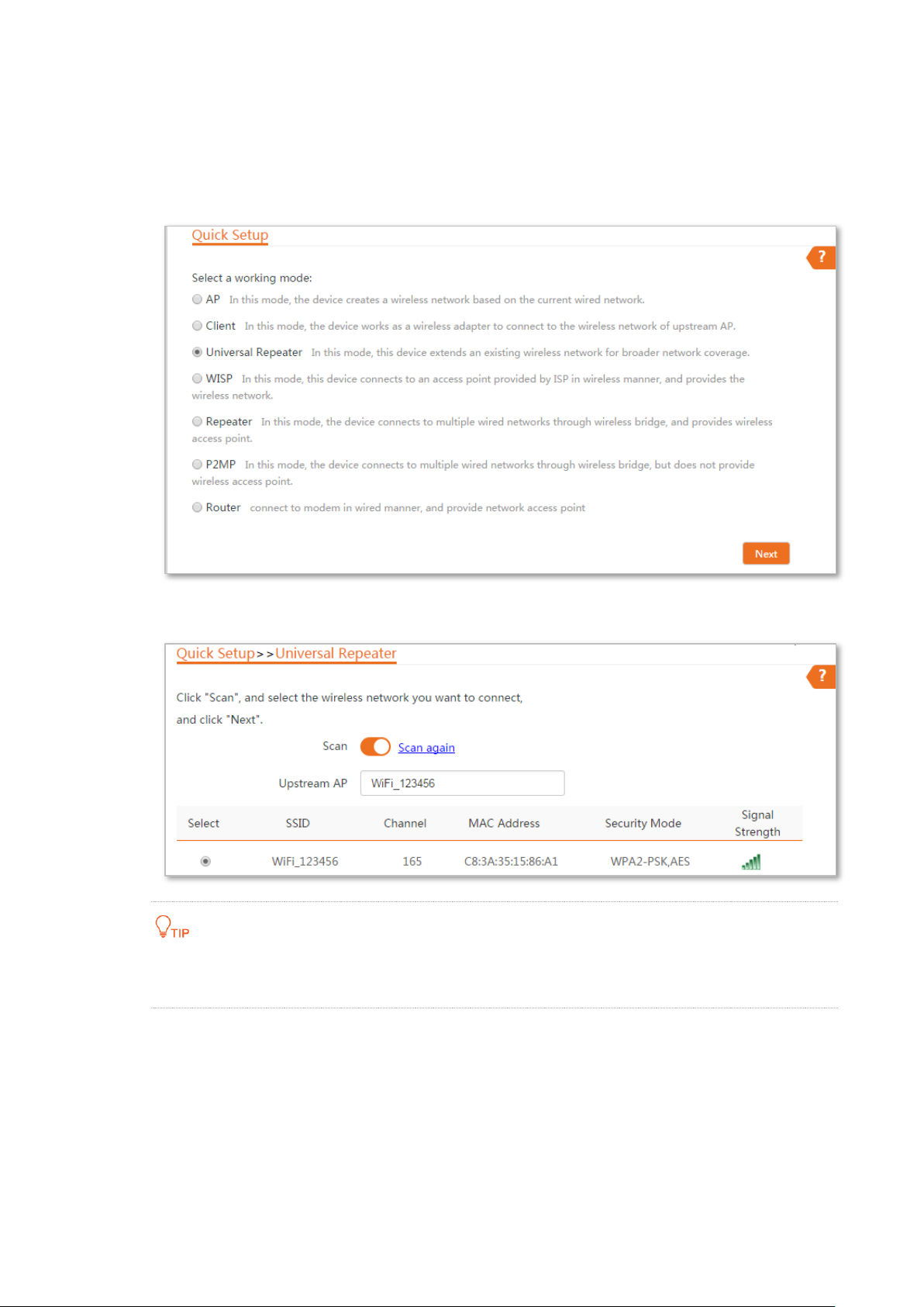
2.4 Universal repeater mode
In Universal Repeater mode, this device expands your WiFi network for broader network coverage.
Advantage of Universal Repeater compared with Repeater mode: This mode does not require that
the upstream AP supports WDS function.
Application scenario
Network requirement: You want to use the CPE to extend your existing wireless network. And your
existing router does not support WDS mode.
Configuration procedure of setting Universal Repeater mode
Step 1 Log in to the web UI of the CPE and choose Quick Setup to enter the configuration page.
Step 2 Select Universal Repeater, and click Next.
16
Page 24
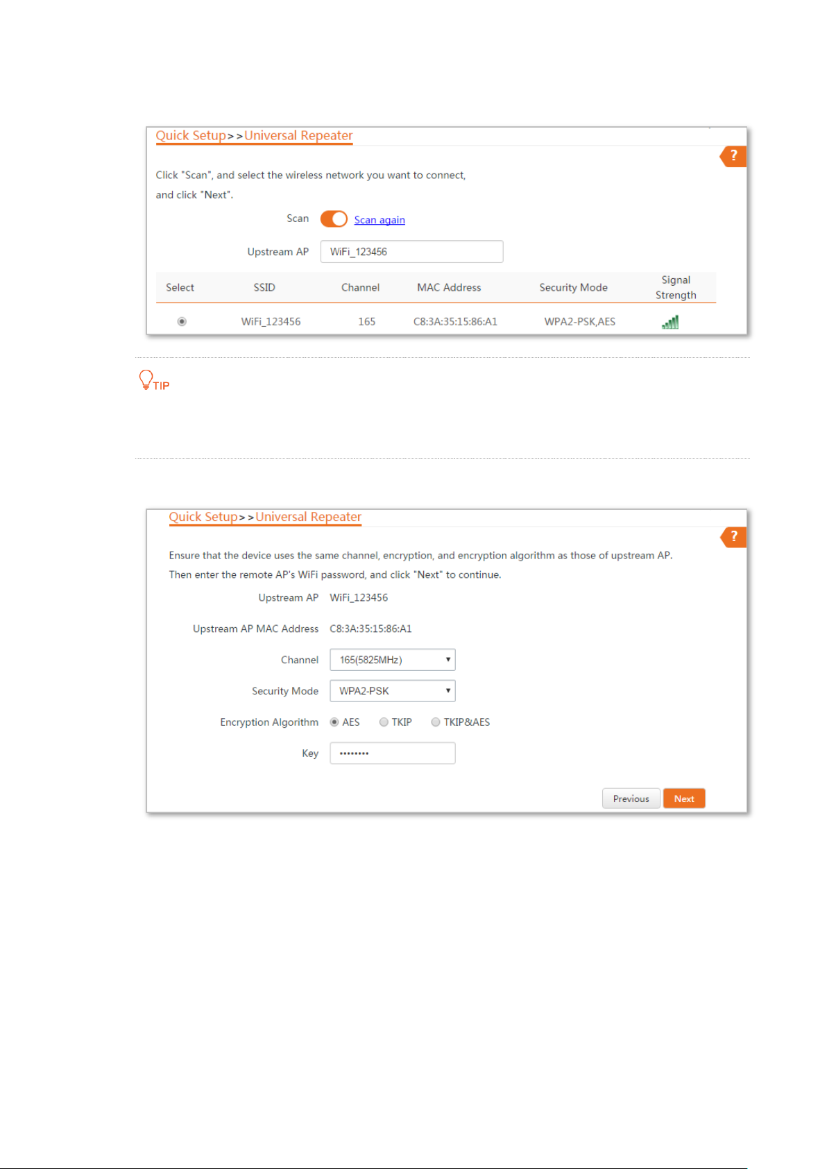
Step 3 Select the SSID of the router and click Next.
If you cannot find the SSID of the router from the list, ensure that the 5 GHz WiFi network
of the router is enabled. Only the WiFi networks at 5 GHz band will be displayed in the list.
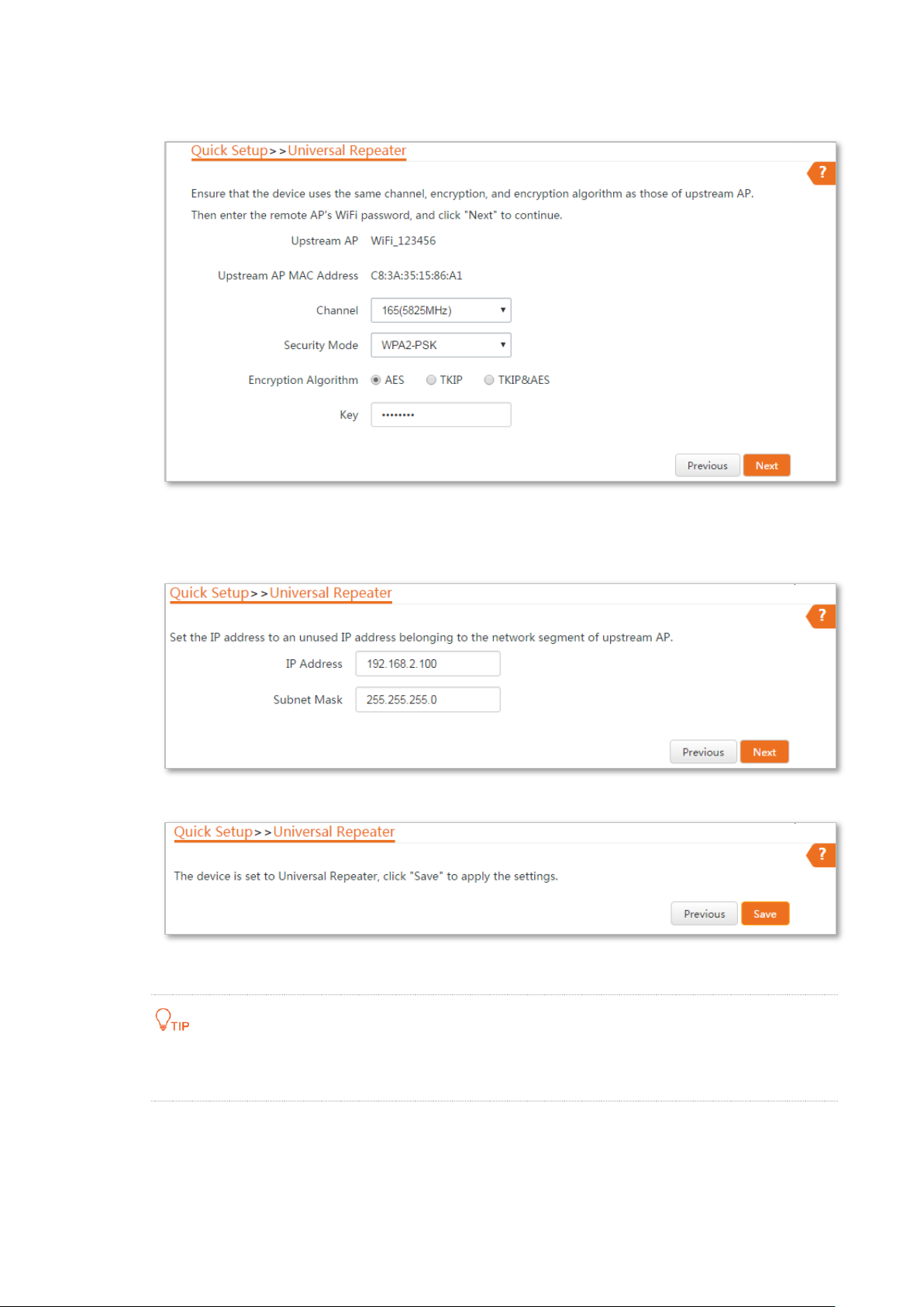
Step 4 Enter the WiFi password of the router in the Key text box, and click Next.
17
Page 25
Name
Description
Working modes
It specifies the working mode of this device.
Universal Repeater mode: in this mode, the device expands your WiFi network for
broader network coverage.
Advantage of Universal Repeater compared with Repeater mode: This mode does not
require that the upstream AP supports WDS function.
Upstream AP
It specifies the wireless network name (SSID) of the upstream AP.
Channel
It specifies the operating channel of the WiFi network to be bridged. It will be
automatically populated when you select an SSID to bridge.
Security Mode
It specifies the security mode of the WiFi network to be bridged. It will be automatically
populated when you select an SSID to bridge. If the WiFi network to be bridged has a WiFi
password, you need to enter the password manually.
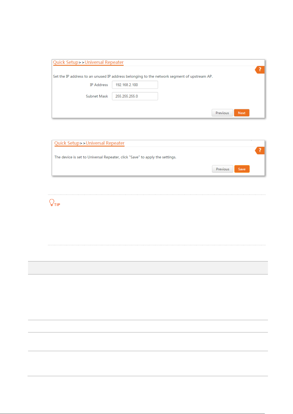
Step 5 Set the IP address to an unused IP address belonging to the same network segment as
that of the router. For example, if the IP address of the router is 192.168.2.1, you can set
this device’s IP address to 192.168.2.X (X ranges from 2 to 254). Then click Next.
Step 6 Click Save, and wait until the device reboots to activate the settings.
----End
If you cannot find any SSID from the list, choose Wireless > Basic and enable the wireless function.
Then try again.
If you cannot find the SSID of CPE1 from the list, adjust the direction of CPE2, and move it close to
the CPE1
Parameters description
18
Page 26
SSID: WiFi_123456
Password: 12345678
CPE: Universal Repeater mode
Computer
Example of universal repeater mode
Network requirement
You are in a WiFi dead zone or a place with weak wireless signal, and have a wireless router that
does not support WDS function. Now you want to have a larger WiFi network coverage through
your home or office.
Solution
Set the CPE to Universal Repeater mode, and extend the WiFi network of the router.
Assume that the SSID and password of the router are shown as follows:
− SSID: WiFi_123456
− Password: 12345678
Network topology
19
Page 27
Configuration procedure
Step 1 Log in to the web UI of the CPE and choose Quick Setup to enter the configuration page.
Step 2 Select Universal Repeater, and click Next.
Step 3 Select the SSID of the router, which is WiFi_123456 in this example, and click Next.
If you cannot find the SSID of the router from the list, ensure that the 5 GHz WiFi network
of the router is enabled. Only the WiFi networks at 5 GHz band will be displayed in the list.
20
Page 28
Step 4 Enter the WiFi password of the router in the Key text box, and click Next.
Step 5 Set the IP address to an unused IP address belonging to the same network segment as
that of the router. For example, if the IP address of the router is 192.168.2.1, you can set
this device’s IP address to 192.168.2.X (X ranges from 2 to 254). Then click Next.
Step 6 Click Save, and wait until the device reboots to activate the settings.
----End
You can check the SSID and key of the CPE by choosing Wireless > Basic after logging in to
the web UI.
21
Page 29
WISP mode
ISP hotspot
Router
Verification
Your wireless devices can search the SSID of the CPE, and connect to its wireless network for
internet access.
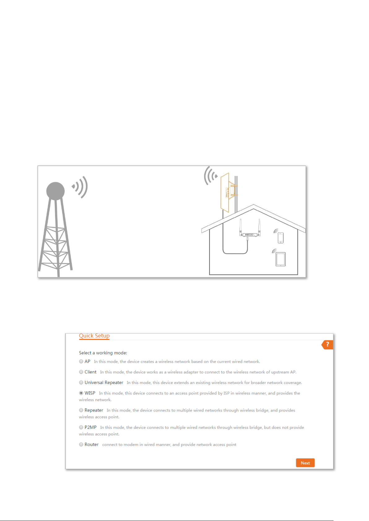
2.5 WISP mode
In WISP mode, this device connects to an access point provided by ISP in wireless manner, and
allowed the wireless devices to connect to the internet.
Application scenario
Network requirement: You want to use the CPE to extend the ISP hotspot to your home.
Configuration procedure of setting WISP mode
Step 1 Log in to the web UI of this CPE and choose Quick Setup to enter the configuration page.
Step 2 Select WISP, and click Next.
22
Page 30
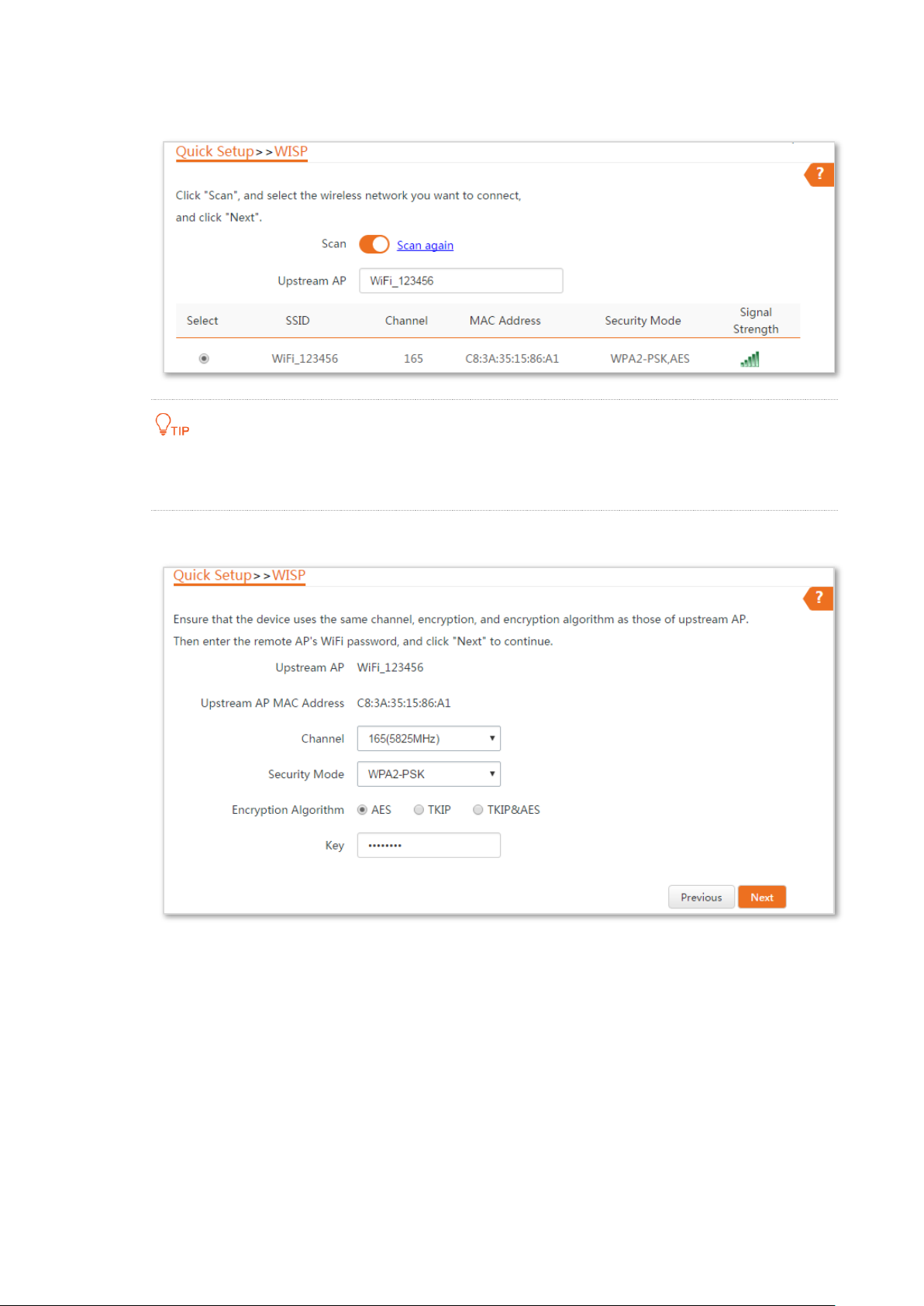
Step 3 Select the SSID of your ISP (Internet Service Provider) hotspot and click Next.
If you cannot find the ISP hotspot from the list, ensure that the hotspot is at 5 GHz. Only
the WiFi networks at 5 GHz band will be displayed in the list.
Step 4 Enter the WiFi password of your ISP hotspot in the Key text box, and click Next.
23
Page 31

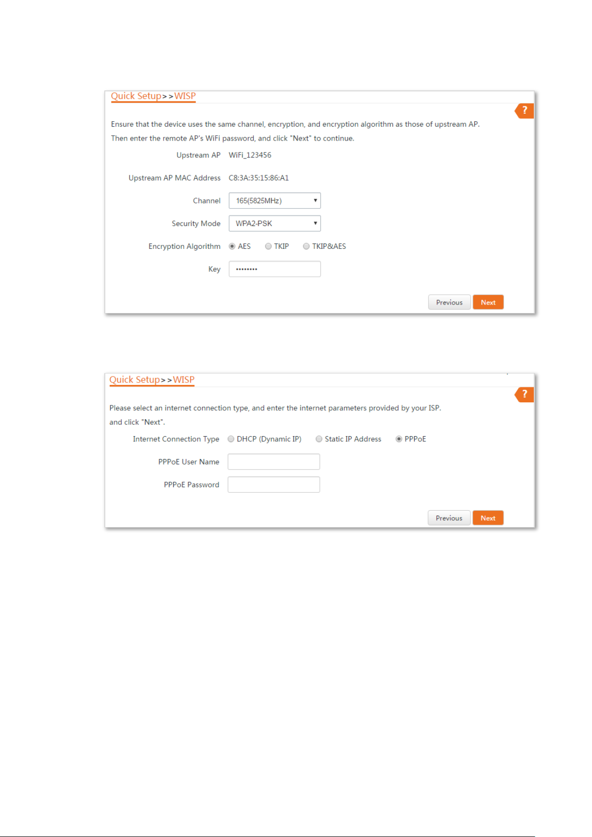
Step 5 Select the Internet Connection Type of your ISP hotspot, which is PPPoE in this example.
Enter the PPPoE user name and password provided by your ISP, and click Next.
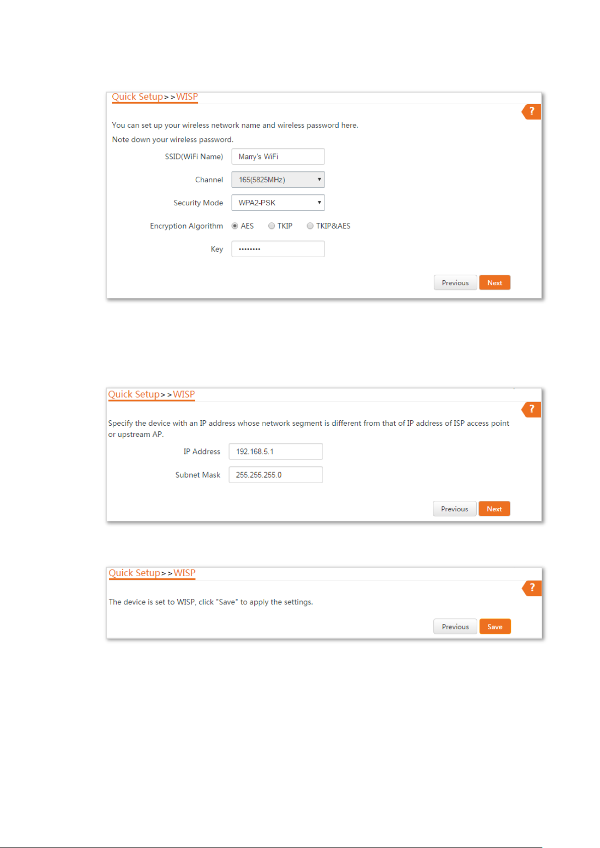
Step 6 Customize the SSID and key, and click Next.
Step 7 Set an IP address belonging to different network segment as that of your ISP hotspot. For
example, if the IP address of your ISP hotspot is 192.168.2.1, you can set this device’s IP
address to 192.168.X.1 (X ranges from 0 to 254 excluding2) which is also the login IP
address of the CPE. Then click Next.
24
Page 32

Name
Description
Working modes
It specifies the working mode of this device.
WISP mode: in this mode, the device connects to an access point provided by ISP
in wireless manner.
Upstream AP
It specifies the wireless network name (SSID) of the upstream AP.
Channel
It specifies the operating channel of the WiFi network to be bridged. It will be
automatically populated when you select an SSID to bridge.
Security Mode
It specifies the security mode of the WiFi network to be bridged. It will be
automatically populated when you select an SSID to bridge. If the WiFi network to
be bridged has a WiFi password, you need to enter the password manually.
Internet Connection Type
DHCP (Dynamic IP): The device obtains IP address and other parameters form the
DHCP server of upstream device for internet access.
Static IP Address: The device access the internet by setting the IP address, subnet
mask, default gateway and DNS server IP addresses manually.
PPPoE: The device access the internet using the PPPoE user name and password
provided by the ISP.
Step 8 Click Save, and wait until the device reboots to activate the settings.
----End
When LED1, LED2, and LED3 of the CPE are blinking, the device is connected to your ISP hotspot
successfully.
You can check the SSID and key of the CPE by choosing Wireless > Basic after logging in to
the web UI.
Parameters description
25
Page 33

SSID: WiFi_123456
Password: 12345678
CPE: WISP mode
ISP hotspot
Router
Example of WISP mode
Network requirement
You live in countryside, and it is not convenient for you to connect the nearest ISP base station
using Ethernet cables. So you want to extend the ISP hotspot to your home in wireless manner.
Solution
Set the CPE to WISP mode, and bridge to the ISP hotspot.
Assume that the SSID and password of the ISP hotspot are:
− SSID: WiFi_123456
− Password: 12345678
Network topology
26
Page 34

Configuration procedure
Step 1 Log in to the web UI of this CPE and choose Quick Setup to enter the configuration page.
Step 2 Select WISP, and click Next.
Step 3 Select the SSID of your ISP (Internet Service Provider) hotspot, which is WiFi_123456 in
this example, and click Next.
If you cannot find the ISP hotspot from the list, ensure that the hotspot is at 5 GHz. Only
the WiFi networks at 5 GHz band will be displayed in the list.
27
Page 35
Step 4 Enter the WiFi password of your ISP hotspot in the Key text box, and click Next.
Step 5 Select the Internet Connection Type of your ISP hotspot, which is PPPoE in this example.
Enter the PPPoE user name and password provided by your ISP, and click Next.
28
Page 36
Step 6 Customize the SSID and key, and click Next.
Step 7 Set an IP address belonging to different network segment as that of your ISP hotspot. For
example, if the IP address of your ISP hotspot is 192.168.2.1, you can set this device’s IP
address to 192.168.X.1 (X ranges from 0 to 254 excluding2) which is also the login IP
address of the CPE. Then click Next.
Step 8 Click Save, and wait until the device reboots to activate the settings.
----End
When LED1, LED2, and LED3 of the CPE are blinking, the device is connected to your ISP hotspot
successfully.
29
Page 37

You can check the SSID and key of the CPE by choosing Wireless > Basic after logging in to
the web UI.
Verification
Your wired and wireless devices can connect your router which is connected to the CPE for internet
access.
30
Page 38

CPE1 in Repeater mode
CPE2 in Repeater mode
CPE3 in Repeater mode
Switch
Switch
Switch
CPE2: Repeater mode
CPE1: Repeater mode
Switch
Switch
Router
Computer
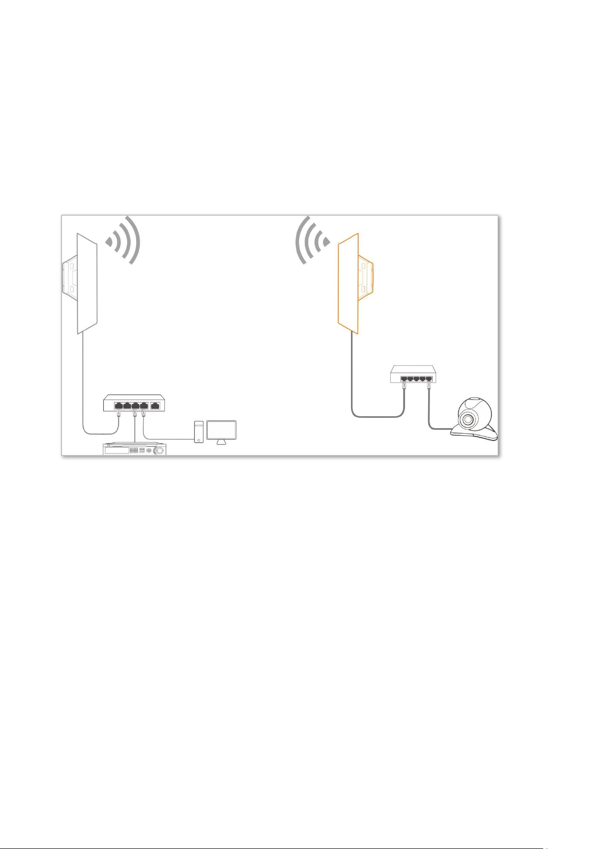
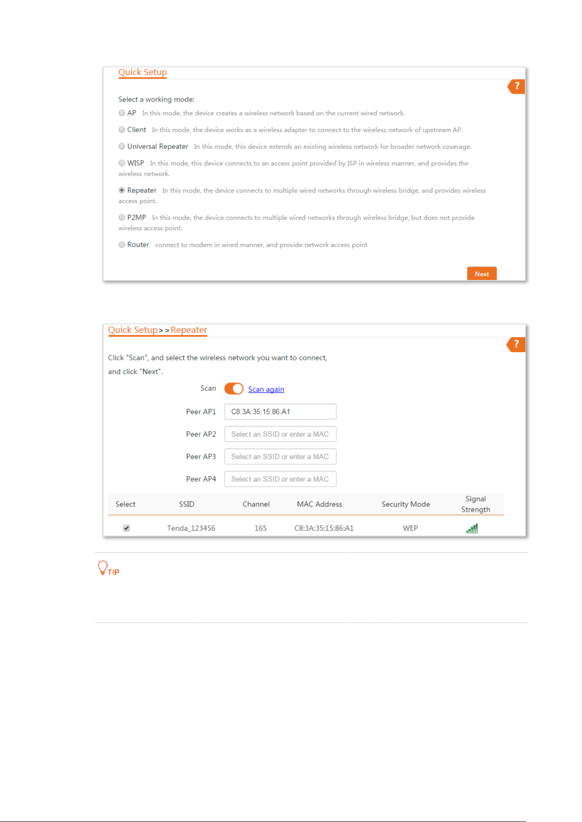
2.6 Repeater mode
In Repeater mode, this device connects 2 or more (this device supports 4 at most) wired networks
with a wireless link, and can be connected with both wired and wireless clients. To use this
function, the peer AP is required to support WDS function.
Application scenario
Network requirement: You want to combine multiple wired networks into one in wireless manner.
Configuration procedure of one to one bridging
Assume that the wireless parameters of CPE1 are as follows:
− SSID: Tenda_123456
− Channel: 165
− Security mode: WEP
− Authentication type: Shared
− Key1 to key4: 12345
31
Page 39

Step 1 Configure the wireless settings of CPE2.
1. Log in to the web UI of CPE2, and choose Wireless > Basic to enter the configuration
page.
2. Change the SSID, which is Tenda_123 in this example.
3. Set the Channel to the same as that of CPE1, which is 165 in this example.
4. Set the Security Mode to the same as that of CPE1, which is WEP in this example.
5. Click Save to apply the settings.
Step 2 Set CPE2 to the Repeater mode.
1. Log in to the web UI of CPE2 and choose Quick Setup to enter the configuration page.
2. Select the SSID of CPE1, which is Tenda_123456 in this example, and click Next.
32
Page 40
3. Select the SSID of CPE1 from the list and click Next.
Only the WiFi networks which are not encrypted or encrypted using the WEP mode can be
found on the list.
33
Page 41

4. Set the Authentication Type and Default Key to the same as those of CPE1, enter the key
1, key2, key 3 and key4, and click Next.
5. Set the IP address to an unused IP address belonging to the same network segment as
that of CPE1. For example, if the IP address of CPE1 is 192.168.2.1, you can set this
device’s IP address to 192.168.2.X (X ranges from 2 to 254). Then click Next.
6. Click Save, and wait until the device reboots to activate the settings.
34
Page 42

Name
Description
Working modes
It specifies the working mode of this device.
Repeater mode: in this mode, the device can connect 2 or more (this device supports 4
at most) wired networks with a wireless link, and can be connected with both wired and
wireless clients. To use the Repeater function of this device, the peer AP is required to
support WDS function, and use the same radio band as that of this device.
Peer AP
It specifies the wireless network name (SSID) of the peer AP.
Channel
It specifies the operating channel of the WiFi network to be bridged. It will be
automatically populated when you select an SSID to bridge.
Security Mode
It specifies the security mode of the WiFi network to be bridged. It will be automatically
populated when you select an SSID to bridge.
The Repeater mode only supports WEP and None security modes.
Step 3 Perform the procedure in Step 2 above to set CPE1 to the Repeater mode.
----End
You can check the SSID and key of the CPE by choosing Wireless > Basic after logging in to
the web UI.
Parameters description
35
Page 43

CPE1: Repeater mode
CPE2: Repeater mode
CPE3: Repeater mode
Router
Switch
Switch
Configuration procedure of one to multiple briding
Assume that the wireless parameters of CPE1 are shown as follows:
− IP Address: 192.168.2.1
− SSID: Tenda_123456
− Channel: 165
− Security mode: None
Step 1 Configure the wireless settings of CPE2.
1. Log in to the web UI of CPE2, and choose Wireless > Basic to enter the configuration
page.
2. Change the SSID, which is Tenda_1 in this example.
3. Set the Channel to the same as that of CPE1, which is 165 in this example.
4. Set the Security Mode to the same as that of CPE1, which is None in this example.
5. Click Save to apply the settings.
36
Page 44

Step 2 Set CPE2 to the Repeater mode.
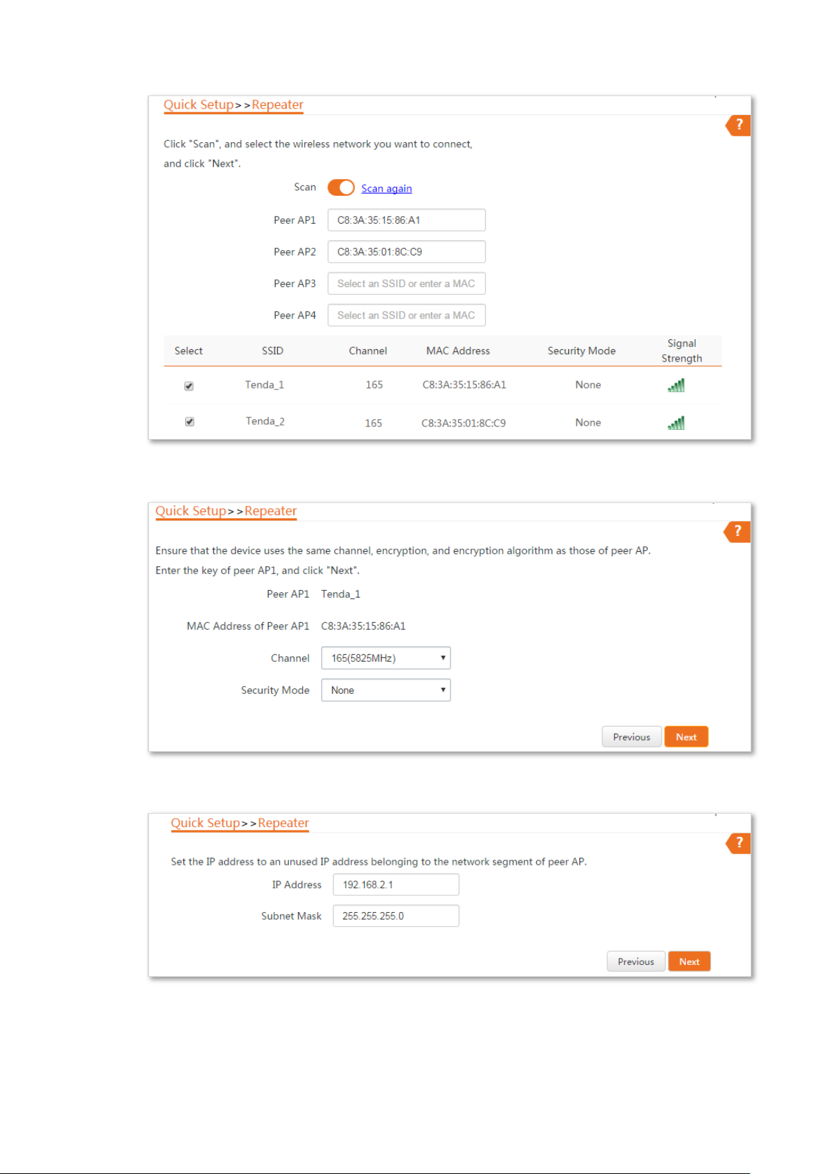
1. Choose Quick Setup, and select Repeater.
2. Select the SSID of CPE1 from the list, which is Tenda_123456 in this example, and click
Next.
If you cannot scan the SSID of CPE1 from the list, choose Wireless > Basic and enable the
wireless function. Then try again.
37
Page 45

3. Click Next directly on the following page.
4. Set the IP address to an unused IP address belonging to the same network segment as
that of CPE1. For example, if the IP address of the CPE1 is 192.168.2.1, you can set this
device’s IP address to 192.168.2.X (X ranges from 2 to 254). Then click Next.
38
Page 46

5. Click Save, and wait until the device reboots to activate the settings.
Step 3 Perform Step 1 and Step 2 above to change the wireless settings of CPE3, whose SSID is
Tenda_2 in this example, set it to Repeater mode, and bridge to CPE1.
Step 4 Set CPE1 to Repeater mode and bridge to CPE2 and CPE3.
1. Log in to the web UI of CPE1, and choose Quick Setup to enter the configuration page.
2. Select Repeater mode, and click Next.
3. Select SSIDs of CPE2 and CPE3, and click Next.
4. Click Next at the bottom of the following page.
39
Page 47

5. Click Next on the following page.
6. Click Next.
7. Click Save, and wait until the device reboots to activate the settings.
----End
40
Page 48

CPE1: P2MP mode
CPE2: P2MP mode
2.7 P2MP mode
In P2MP mode, this device connects 2 or more (this device supports 4 at most) wired networks
with a wireless link, but cannot be connected with wireless clients.
The device in P2MP mode can work with the device in Repeater or P2MP mode.
Application scenario
Network requirement: You want to combine two local networks into one in wireless manner.
Configuration procedure
Assume that the related parameters of CPE1 are shown as follows:
− IP Address: 192.168.2.1
− SSID: Tenda_1
− Channel: 165
− Security Mode: None
Step 1 Change the wireless settings of CPE2.
1. Log in to the web UI of CPE2, and choose Wireless > Basic to enter the configuration
page.
2. Change the SSID, which is Tenda_2 in this example.
3. Set the Channel to the same as that of CPE1, which is 165 in this example.
4. Set the Security mode to the same as that of CPE1, which is None in this example.
5. Click Save to apply the settings.
41
Page 49
Step 2 Set CPE2 to P2MP mode and bridge to CPE1.
1. Choose Quick Setup, select P2MPmode, and click Next.
2. Select the SSID of CPE1, which is Tenda_1 in this example, and click Next.
42
Page 50

If you cannot find any SSID from the list, choose Wireless > Basic and enable the wireless function.
Then try again.
If you cannot find the SSID of CPE1 from the list, adjust the direction of CPE2, and move it close to
the CPE1.
3. Click Next on the following page.
4. Set the IP address to an unused IP address belonging to the same network segment as
that of CPE1. For example, if the IP address of CPE1 is 192.168.2.1, you can set the IP
address of the device to 192.168.2.X (X ranges from 2 to 254). Then click Next.
5. Click Save, and wait until the device reboots to activate the settings.
Step 3 Set CPE1 to P2MP mode and bridge to CPE2.
1. Log in to the web UI of CPE1, and choose Quick Setup to enter the configuration page.
2. Select the SSID of CPE2, which is Tenda_2 in this example, and click Next.
43
Page 51

3. Click Next on the following page.
4. Click Next on the following page.
44
Page 52

Name
Description
Working modes
It specifies the working mode of this device.
P2MP mode: in this mode, the device can connect 2 or more (this device supports 4 at
most) wired networks with a wireless link, but cannot be connected with wireless
clients. P2MP mode is used to achieve communication between multiple offices of an
enterprise in a city.
Peer AP
It specifies the wireless network name (SSID) of the peer AP.
Channel
It specifies the operating channel of the WiFi network to be bridged. It will be
automatically populated when you select an SSID to bridge.
Security Mode
It specifies the security mode of the WiFi network to be bridged. It will be automatically
populated when you select an SSID to bridge.
The P2MP mode only supports WEP and None security modes.
5. Click Save, and wait until the device reboots to activate the settings.
----End
Parameters description
2.8 Example of repeater mode and P2MP mode
Network requirement
You have three offices which are not far away from each other, and only one office has internet
service. Now you want to combine the networks in three offices into one, and provide wireless
networks to wireless devices in the offices without internet service.
Solution
Set CPE1 to P2MP mode, and set CPE2 and CPE3 to Repeater mode.
45
Page 53
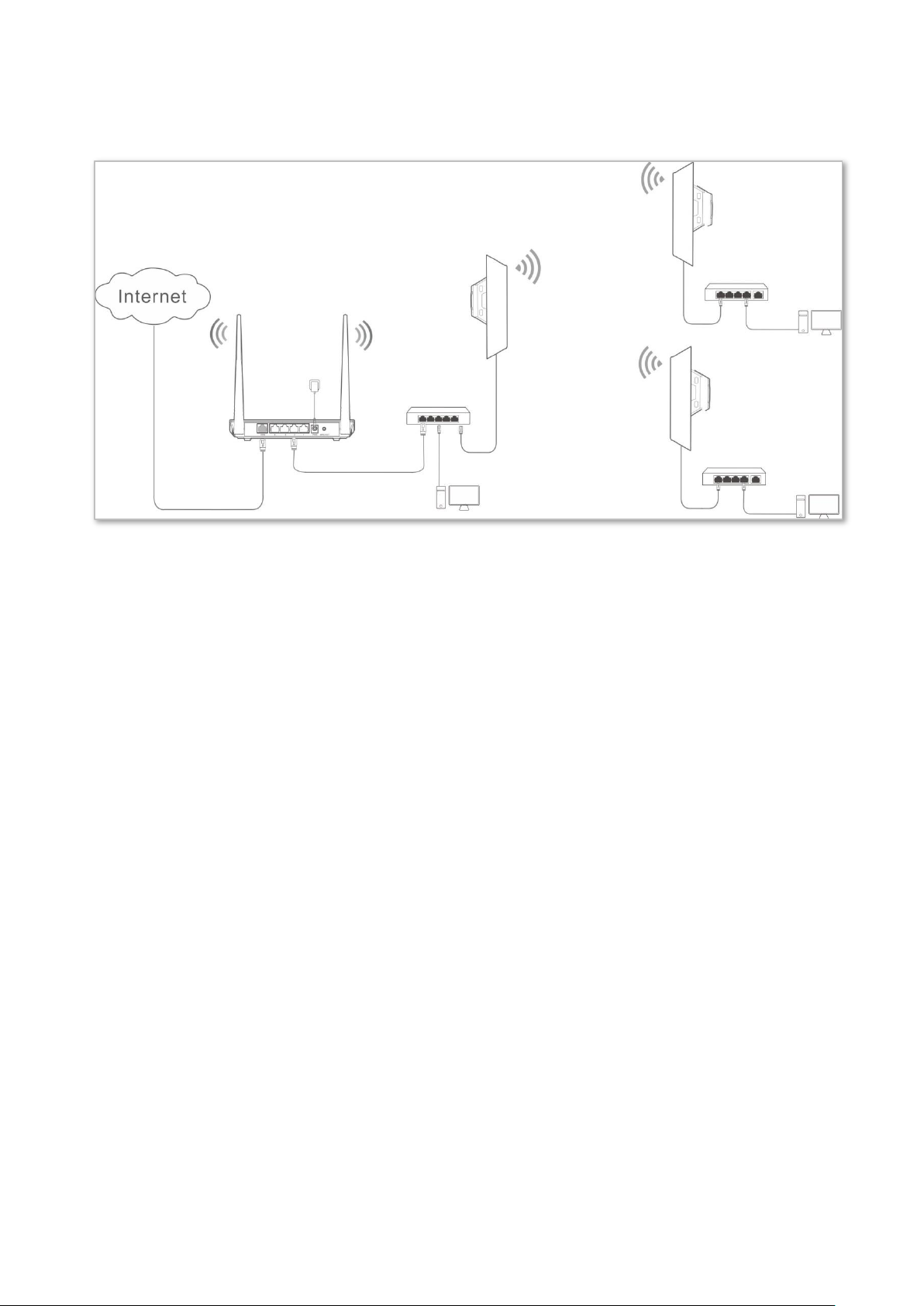
CPE1: P2MP mode
CPE2: Repeater mode
Switch
Computer
Computer
Switch
Switch
Computer
CPE3: Repeater mode
Network typology
Configuration procedure
Assume that the wireless parameters of CPE1 are shown as follows:
− IP Address: 192.168.2.1
− SSID: Tenda_123456
− Channel: 165
− Security mode: None
Step 1 Configure the wireless settings of CPE2.
1. Log in to the web UI of CPE2, and choose Wireless > Basic to enter the configuration
page.
2. Change the SSID, which is Tenda_1 in this example.
3. Set the Channel to the same as that of CPE1, which is 165 in this example.
4. Set the Security Mode to the same as that of CPE1, which is None in this example.
5. Click Save to apply the settings.
46
Page 54
Step 2 Set CPE2 to the Repeater mode.
1. Choose Quick Setup, and select Repeater.
2. Select the SSID of CPE1 from the list, which is Tenda_123456 in this example, and click
Next.
47
Page 55

If you cannot find any SSID from the list, choose Wireless > Basic and enable the wireless function.
Then try again.
If you cannot find the SSID of CPE1 from the list, adjust the direction of CPE2, and move it close to
the CPE1.
3. Click Next directly on the following page.
48
Page 56

4. Set the IP address to an unused IP address belonging to the same network segment as
that of CPE1. For example, if the IP address of the CPE1 is 192.168.2.1, you can set this
device’s IP address to 192.168.2.X (X ranges from 2 to 254). Then click Next.
5. Click Save, and wait until the device reboots to activate the settings.
Step 3 Perform Step 1 and Step 2 above to change the wireless settings of CPE3, whose SSID is
Tenda_2 in this example, set it to Repeater mode, and bridge to CPE1.
Step 4 Set CPE1 to Repeater mode and bridge to CPE2 and CPE3.
1. Log in to the web UI of CPE1, and choose Quick Setup to enter the configuration page.
2. Select Repeater mode, and click Next.
3. Select SSIDs of CPE2 and CPE3, and click Next.
4. Click Next at the bottom of the following page.
49
Page 57
5. Click Next on the following page.
6. Click Next.
7. Click Save, and wait until the device reboots to activate the settings.
50
Page 58

----End
Verification
Wired or wireless devices connected to CPE2 and CPE3 can access the internet.
51
Page 59

Router mode
Modem
2.9 Router mode
In Router mode, this device serves as a router to provide a wireless network.
Application scenario
Network requirement: You want to use the CPE to provide a wireless network and assign IP
addresses to your wireless devices.
Configuration procedure of setting Router mode
Step 1 Log in to the web UI of the CPE, and choose Quick Setup to enter the configuration page.
Step 2 Select Router mode, and click Next.
Step 3 Select your internet connection type, and set the related parameters. Take PPPoE as an
example here.
1. Select PPPoE.
2. Enter the PPPoE user name and password provided by your internet service provider,
which are both admin in this example.
3. Click Next.
Step 4 Set wireless parameters of the CPE.
1. Customize a SSID, which is Tenda_123456 in this example.
2. Select a security mode, which is WPA2-PSK in this example.
52
Page 60

Name
Description
Working modes
It specifies the working mode of this device.
Router mode: in this mode, the PoE/LAN port works as the WAN port and is used to
connect to a modem for internet access.
Internet Connection
Type
The device in Router mode supports three internet connection types:
DHCP (Dynamic IP): The device obtains the IP address and other parameters from the
DHCP server of upstream device for internet access.
Static IP Address: The device accesses the internet using the IP address, subnet mask,
default gateway and DNS server IP addresses you manually entered.
PPPoE: The device accesses the internet using the PPPoE user name and password
provided by the ISP.
SSID
It specifies the wireless network name of the device.
Channel
It specifies the operating channel of the WiFi network to be bridged. It will be
automatically populated when you select an SSID to bridge.
3. Set a Key for the wireless network, and click Next.
Step 5 Click Save, and wait until the device reboots to activate the settings.
----End
Parameters description
53
Page 61

Name
Description
Security Mode
It specifies the security mode of the WiFi network of the device. It includes None,
WPA-PSK, WPA2-PSK, and Mixed WPA/WPA2-PSK.
Clicking the hyperlink navigates you to the elaborated description of the corresponding
security mode.
Router mode
Modem
2.9.2 Example of router mode
Network requirement
You want to use the CPE to server as a wireless router.
Solution
Set the CPE to Router mode.
Assume that:
− Your internet connection type: PPPoE
− User name: admin
− Password: admin
Network typology
Configuration procedure
Step 1 Log in to the web UI of the CPE, and choose Quick Setup to enter the configuration page.
Step 2 Select Router mode, and click Next.
Step 3 Select PPPoE, enter admin in both PPPoE User Name and PPPoE Password boxes, and
click Next.
54
Page 62

Step 4 Set wireless parameters of the CPE.
1. Customize a SSID, which is Tenda_123456 in this example.
2. Select a security mode, which is WPA2-PSK in this example.
3. Set a Key for the wireless network, and click Next.
Step 5 Click Save, and wait until the device reboots to activate the settings.
----End
Verification
Wireless devices connected to the wireless network of the CPE can access the internet.
55
Page 63

3 Web UI
3.1 Login
When you log in to the web UI at the first time, follow the steps below:
Step 1 Connect the computer to the device.
1. Uncover the housing of the device.
2. Use an Ethernet cable to connect the PoE/LAN port of the device to the PoE port of the
included PoE injector.
3. Use the included power adapter to connect the PoE injector to a power source. The
LAN/WAN LED indicator of the device lights up.
4. Use an Ethernet cable to connect your computer to the LAN port of the PoE injector.
Step 2 Start a web browser on your computer, and visit 192.168.2.1. Enter your user name and
password (default: admin), and click Login.
56
Page 64

----End
If this page does not appear, please refer to Q1 in FAQ.
Then the following page appears.
When you log in to the web UI after the device is configured, select one of the following
situations to perform.
If you want to log in to the CPE in Client mode (LED1, LED2, and LED3 are blinking) after
one-to-one auto-bridge, perform the following procedure.
Step 1 Connect the computer to the PoE/LAN port of one of the CPEs, or connect to the wireless
network using the SSID and password set on the CPE in AP mode.
Step 2 Start a web browser on your computer, and visit 192.168.2.2. Enter your user name and
password you set (default: admin), and click Login.
57
Page 65

If you want to log in to the CPEs in client mode (LED1, LED2, and LED3 are blinking) after
one-to-multiple bridge, connect the computer to the PoE/LAN port of the corresponding
CPE you want to log in one by one using an Ethernet cable, and visit 192.168.2.2.
----End
If you want to log in to the CPE in Router mode, perform the following procedure.
Step 1 Connect the computer to the wireless network using the SSID and password set on the
CPE.
Step 2 Visit the LAN IP address you set for the CPE.
----End
3.2 Logout
You can click Logout on the upper-right corner of the web UI to logout. When you close the web
browser, the system logs you out as well.
If you log in to the web UI of the device and perform no operation within the login timeout interval
(default: 5 minutes), the device logs you out.
58
Page 66

No.
Name
Description
❶
Level-1 navigation tree
The navigation bars and tab pages display the function menu of the
device. When you select a function in navigation bar, the
configuration of the function appears in the configuration area.
❷
Level-2 navigation tree
❸
Tab page area
❹
Configuration area
It enables you to view and modify configuration.
Common Buttons
Description
It is used to update the content of the current page.
It is used to save the configuration on the current page and enable the configuration
to take effect.
It is used to go back to the original configuration without saving the configuration on
the current page.
It is used to view help information corresponding to the settings on the current page.
1 2 3
4
3.3 Web UI layout
The web UI of the device is composed of 4 parts, including the level-1 navigation tree, level-2
navigation tree, tab page area, and configuration area. See the following figure.
3.4 Common buttons
The following table describes the common buttons available on the web UI.
59
Page 67

Name
Description
Device Name
It specifies the name of this device. Different device names help you manage
multiple devices on LAN easily. You can change the name of this device on the
Network > LAN Setup page when the device works in AP, Client, Universal
Repeater, Repeater, and P2MP modes. When the device works in WISP or Router
mode, it displays the model of the device, and cannot be changed.
Uptime
It specifies the time that has elapsed since the device was started last time.
System Time
It specifies the current system time of this device.
Hardware Version
It specifies the hardware version of this device.
RAM
Random Access Memory. It specifies the memory usage of this device.
4 Status
This module includes three parts: system status, wireless status, and statistics.
4.1 System status
Log in to the web UI of the device, and choose Status. You can view the system status here.
If this device is set to AP mode, Client mode, Universal Repeater mode, Repeater mode or P2MP
mode, the system status is shown as follows:
Parameters description
60
Page 68

Name
Description
WLAN MAC Address
It specifies the MAC address of the wireless network of this device.
LAN Speed
It specifies the PoE/LAN port speed and duplex mode of this device.
LAN IP Address
It specifies the IP address (also named management IP address) of this device. By
default, it is 192.168.2.1. You can access the web UI of this device using this IP
address.
Firmware Version
It specifies the system software version number of this device.
CPU
Central Processing Unit. It specifies the CPU usage of this device.
LAN MAC Address
It specifies the MAC address of LAN port of this device. When connecting to
another device using an Ethernet cable, the device uses this MAC address to
communicate with the device.
Name
Description
Connection Type
It specifies the internet connection type of this device in WISP or Router mode.
Connection Status
It specifies the connection status of WAN port of this device in WISP or Router
If the device is set to WISP or Router mode, the system status is shown as follows:
Parameters description
61
Page 69

Name
Description
mode.
WAN IP Address
It specifies the IP address of WAN port of this device in WISP or Router mode.
Default Gateway
It specifies the default gateway address of this device in WISP or Router mode.
Primary DNS Server
It specifies the IP address of primary DNS server of this device in WISP or Router
mode.
Secondary DNS Server
It specifies the IP address of secondary DNS server of this device in WISP or
Router mode.
62
Page 70

Name
Description
Working Mode
It specifies the working mode the device operates.
SSID
It specifies the wireless network name of this device.
Security Mode
It specifies the security mode of the wireless network of this device.
Channel/Radio Band
It specifies the channel and radio band used by this device to transmit radio signals.
Channel Bandwidth
It specifies the channel bandwidth of this device.
TX Power
It specifies the transmitted power of this device.
Wireless Client
It specifies the number of wireless clients connected to this device.
AP’s MAC Address
It displays No Peer AP if the device works in AP or Router mode. And in other
modes, it displays the MAC address of peer AP to which this device bridged.
Signal Strength
It displays the signal strength of the first device connected to the wireless network
of the device when it works in AP or Router mode. It displays the received signal
strength from peer AP when the device works in Client, Universal Repeater, WISP,
Repeater or P2MP mode.
Background Noise
It specifies the strength of radio interference signals in the ambient environment
that interfere with the channel of this device. Larger absolute value indicates less
4.2 Wireless status
Log in to the web UI of the device, and choose Status. You can view wireless status here, including
working mode, SSID, security mode, and so on.
Parameters description
63
Page 71

Name
Description
interference. For example, -95 dBm indicates less interference than -75 dBm.
TX/RX Link
It specifies the number of spatial streams the device is transmitting or receiving.
Transmit/Receive Speed
It specifies the wireless transmitting/receiving rate.
In AP or Router mode: it displays the transmitting/receiving rate of the first device
connected to the wireless network of this device.
In Client, Universal Repeater, WISP, Repeater, or P2MP mode: it displays
transmitting/receiving rate of this device.
TD-MAX
It specifies the status of the TD-MAX function.
64
Page 72
4.3 Statistics
Log in to the web UI of the device, and choose Status. You can view statistics information here,
including throughput, wireless client, interface, ARP table and routing table.
4.3.1 Throughput
It displays the throughput of WLAN and LAN ports here.
65
Page 73
Name
Description
IP Address
It specifies the IP address of the corresponding wireless client.
MAC Address
It specifies the MAC address of the corresponding wireless client.
Signal/Noise
It specifies the WiFi signal strength and electromagnet interference signal strength
of the corresponding wireless client.
Transmit/Receive
It specifies the transmitting and receiving rate of the corresponding client.
CCQ
It specifies the connection quality of the corresponding client. Higher percentage
indicates better connection quality.
Connection Duration
It specifies the time that has elapsed since the wireless client is connected to the
wireless network of the device.
4.3.2 Wireless client
It displays the information of wireless clients when the device works in AP, Repeater, P2MP, or
Router mode.
Parameters description
4.3.3 Upstream AP
This function is available only when the device works in Client, Universal Repeater, or WISP mode.
66
Page 74

Name
Description
IP Address
It specifies the IP address of the upstream device.
MAC Address
It specifies the MAC address of the upstream device.
Signal/Noise
It specifies the WiFi signal strength and electromagnet interference signal strength
of the upstream device.
Transmit/Receive
It specifies the transmitting and receiving rate of the upstream device.
CCQ
It specifies the connection quality of the upstream device. Higher percentage
indicates better connection quality.
Connection Duration
It specifies the time that has elapsed since this device bridges to the upstream
device.
Name
Description
Interface
It displays the wired interface, bridge interface, and WLAN interface of the device.
IP Address
It displays the IP addresses of wired interface, bridge interface, and WLAN interface.
MAC Address
It displays the MAC addresses of wired interface, bridge interface, and WLAN
interface.
Received Packets
It displays the received and transmitted packets of the interface.
Parameters description
4.3.4 Interface
It displays the IP address, MAC address and traffic information of the interfaces of the device.
Parameters description
67
Page 75

Transmitted Packets
Receive Error
It displays the received and transmitted error packets of the interface.
Transmit Error
Name
Description
IP Address
It specifies the IP address of the host in the APR table.
MAC Address
It specifies the MAC address corresponding to the IP address.
Interface
It specifies the interface used to communicate with the host.
4.3.5 ARP table
It specifies the current ARP table of the device.
Parameters description
68
Page 76

Name
Description
Destination Network
It specifies the IP address of the destination network.
Subnet Mask
It specifies the subnet mask of the destination network.
Next Hop
It specifies the IP address of entrance of the next hop route when the packets egress
from the interface of the device.
Interface
It specifies the interface that the packets egress.
4.3.6 Routing table
It specifies the destination networks that the device can access.
Parameters description
69
Page 77

Name
Description
MAC Address
It specifies the MAC address of LAN port.
IP Address Type
It specifies the type of obtaining an IP address. The default is Static IP Address.
Static IP Address: Specify the IP address, subnet mask, default gateway, and DNS
server IP addresses manually.
DHCP (Dynamic IP Address): The device obtains an IP address, subnet mask, default
5 Network
5.1 LAN setup
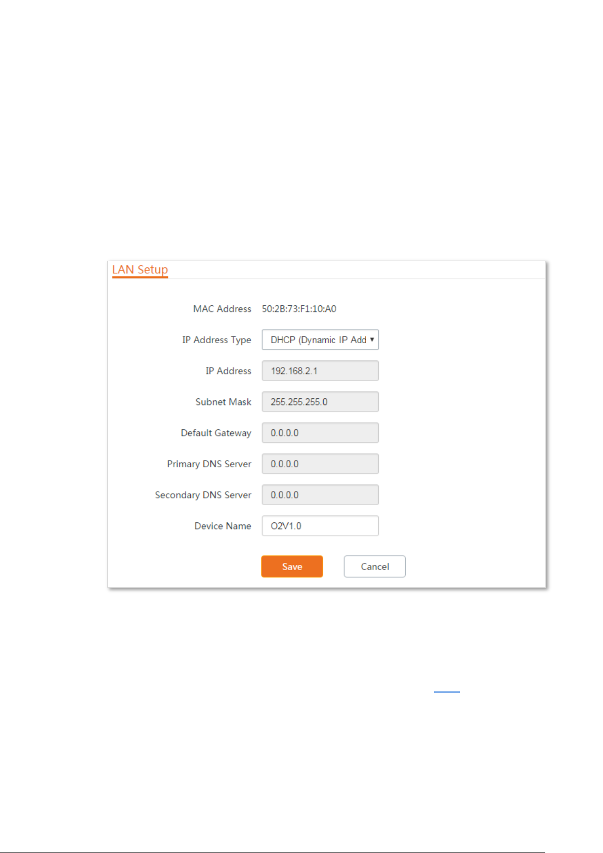
5.1.1 Overview
Log in to the web UI of the device, and choose Network > LAN Setup to enter the page.
This page enables you to view the MAC address of the LAN port, set up the device name, and type
of obtaining an IP address and related parameters.
When the CPE is in AP, Client, Universal Repeater, Repeater, and P2MP modes, the page displays:
Parameters description
70
Page 78

Name
Description
gateway and DNS server IP address from the DHCP server in the network.
If the IP Address Type is set to DHCP (Dynamic IP Address), you need to check the
device’s IP address on the clients list of the DHCP server in the network, and use this
IP address to log in.
IP Address
It specifies the LAN IP address of the device.
Subnet Mask
It specifies the subnet mask corresponding to the LAN IP address of the device. The
default is 255.255.255.0.
Default Gateway
It specifies the default gateway of the device.
You can set it to the IP address of the egress router to enable the device to access the
internet.
Primary DNS Server
It specifies the primary DNS server IP address of the device.
If the egress router has the DNS agency function, it can be set to the LAN IP address
the egress router. Otherwise, specify a DNS server IP address manually.
Secondary DNS Server
It specifies the secondary DNS server IP address of the device.
If there are two DNS server IP addresses, enter one in this box.
Device Name
It specifies the name of the device. The default name indicates the product model
and version.
You are recommended to change the name to indicate the location of the device, so
that you can easily identify the device when there are multiple devices in the
network.
Name
Description
MAC Address
It specifies the MAC address of LAN port.
IP Address Type
It specifies the type of obtaining an IP address. The default is Static IP Address.
When the CPE is in WISP and Router modes, the page displays:
71
Page 79

Name
Description
Static IP Address: Specify the IP address and subnet mask manually.
DHCP (Dynamic IP Address): The device obtains an IP address and subnet mask from
the upstream DHCP server in the network.
If the IP Address Type is set to DHCP (Dynamic IP Address), you need to check the
device’s IP address on the clients list of the DHCP server of the upstream device, and
use this IP address to log in.
IP Address
It specifies the LAN IP address of the device.
Subnet Mask
It specifies the subnet mask corresponding to the LAN IP address of the device. The
default is 255.255.255.0.
5.1.2 Changing the LAN IP address
Manually setting the IP address
In this mode, you must manually set the IP address, subnet mask, gateway IP address, and DNS
server IP addresses of the device. Therefore, this mode is recommended if you need to deploy only
a few devices.
Configuration procedure:
Step 1 Choose Network > LAN Setup to enter the configuration page.
Step 2 Set IP Address Type to Static IP Address.
Step 3 Set IP Address, Subnet Mask, Default Gateway, and Primary DNS Server. If another DNS
server is available, set Secondary DNS Server to the IP address of the additional DNS
server.
Step 4 Click Save.
72
Page 80
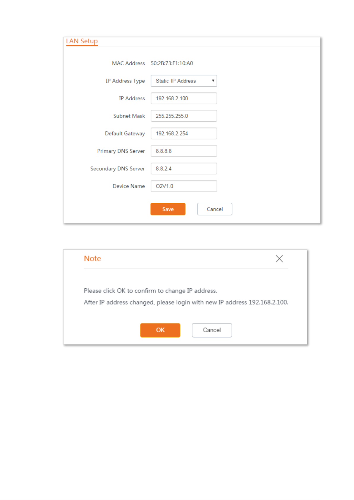
Step 5 Click OK on the pop-up window.
----End
After the configuration, if the new and original IP addresses belong to the same network segment,
you can log in to the web UI of the device by accessing the new IP address.
Otherwise, assign your computer an IP address that belongs to the same network segment as the
new IP address of the device before login with the new IP address.
Assume that: the new IP address of the device is 192.168.1.1, and subnet mask is 255.255.255.0,
then assign an IP address belonging to the same segment.
73
Page 81

1
2
Configuration procedure (OS example: Windows 7):
Step 1 Right-click the icon on the bottom-right corner of the desktop.
Step 2 Click Open Network and Sharing Center.
Step 3 Click Local Area Connection, then click Properties.
74
Page 82
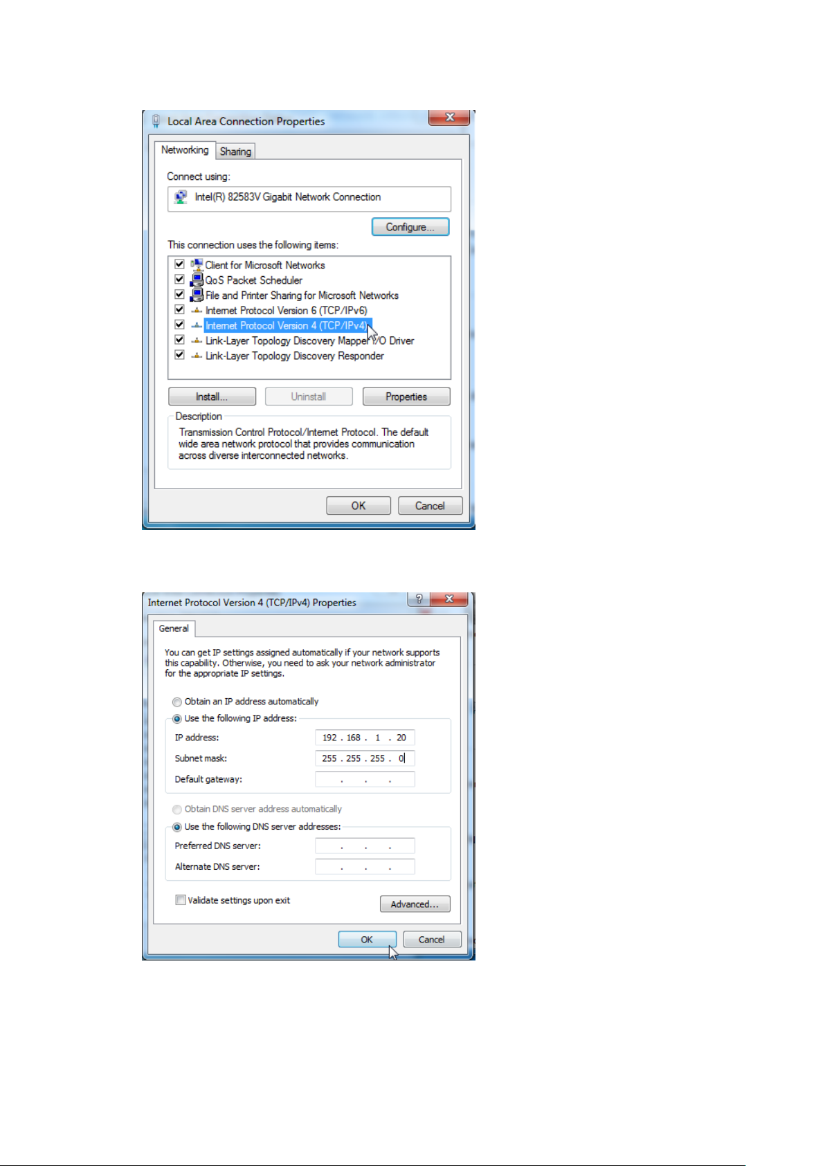
Step 4 Double-click Internet Protocol Version 4 (TCP/IPv4).
Step 5 Select Use the following IP address, set the IP address to 192.168.1.X (X ranges from 2 to
253), the Subnet mask to 255.255.255.0, and click OK.
6. Click OK on the Local Area Connection Properties window, and close the other windows.
----End
75
Page 83
Automatically obtaining an IP address
This mode enables the device to automatically obtain an IP address, a subnet mask, a gateway IP
address, DNS server IP addresses assigned by the DHCP server of the upstream device. If a large
number of devices are deployed, you can adopt this mode to prevent IP address conflicts and
effectively reduce your workload.
Configuration procedure:
Step 1 Choose Network > LAN Setup to enter the configuration page.
Step 2 Set IP Address Type to DHCP (Dynamic IP Address).
Step 3 Click Save.
----End
After the configuration, if you want to re-log in to the web UI of the device, check the new IP
address on the web UI of the upstream device which assigns the IP address to this device. Ensure
that the IP address of the management computer and the IP address of the device belong to the
same network segment, and access the IP address of the device. Refer to steps in the Manually
setting the IP address part to assign an IP address to the computer manually.
76
Page 84
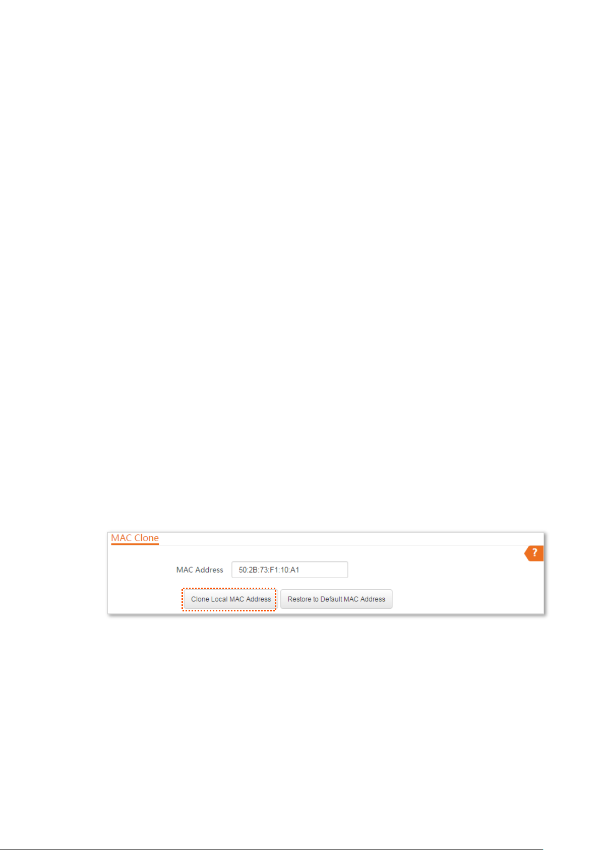
5.2 MAC clone
This function is available only when the device works in WISP or Router mode.
5.2.1 Overview
If the device cannot access the internet after configuring internet settings, your ISP may have
bound your internet service account with the MAC address of your computer that was used to
verify the internet connectivity after you subscribed to the internet service. Therefore, only this
computer can access the internet with the account.
In this case, you need to clone the MAC address of this computer to the WAN port of this device
for internet access.
5.2.2 Cloning a MAC address
Select one of the following methods to clone the MAC address according to your networking
scenario.
Method 1
If you can find the computer that can access the internet after it connects to the modem directly,
perform the following steps:
Step 1 Connect the computer to the device.
Step 2 Log in to the web UI.
Step 3 Choose Network > MAC Clone to enter the configuration page.
Step 4 Click Clone Local MAC Address.
Step 5 Click Save.
----End
Method 2
If you cannot find the computer that can access the internet after it connects to the modem
directly, but you know the MAC address of this computer, perform the following steps:
Step 1 Connect another device (such as a smart phone or tablet) to the device.
Step 2 Log in to the web UI.
77
Page 85
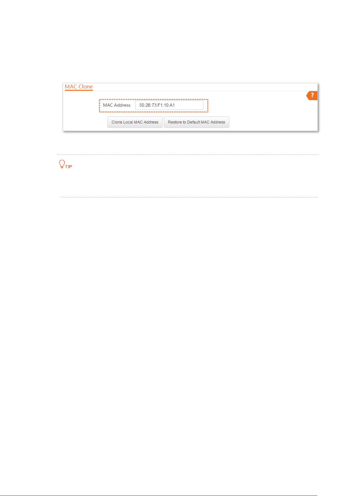
Step 3 Choose Network > MAC Clone.
Step 4 Enter the MAC address of the computer that can access the internet in the MAC Address
box.
Step 5 Click Save.
----End
If you want to restore the MAC address to factory settings, choose Network > MAC
Clone, click Restore to Default MAC Address, and click Save.
78
Page 86
*
*
*
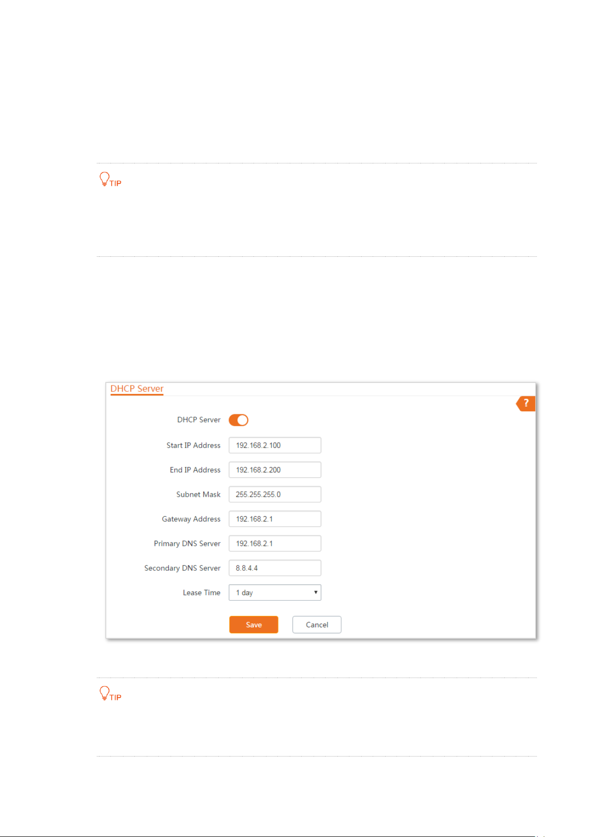
5.3 DHCP server
5.3.1 Overview
The device provides a DHCP server function to assign IP addresses to clients on the LAN. By default,
the DHCP server function is disabled.
If the new and original IP addresses of the LAN port belong to different network segment,
the system changes the IP address pool of the DHCP server of the device, so that the IP
address pool and the new IP address of the LAN port belong to the same network
segment.
5.3.2 Configuring the DHCP server
Step 1 Choose Network > DHCP Server to enter the configuration page.
Step 2 Enable the DHCP server.
Step 3 Set the parameters. Generally, you need to set only Gateway Address and Primary DNS
Server.
Step 4 Click Save.
----End
If another DHCP server is available on your LAN, ensure that the IP address pool of the
device does not overlap with the IP address pool of that DHCP server. Otherwise, IP
address conflicts may occur.
79
Page 87

Name
Description
DHCP Server
It specifies whether to enable the DHCP server function of the device. By default, it
is disabled.
Start IP Address
It specifies the start IP address of the IP address pool of the DHCP server. The
default value is 192.168.2.100.
End IP Address
It specifies the end IP address of the IP address pool of the DHCP server. The
default value is 192.168.2.200.
The start and end IP addresses must belong to the same network segment as the IP address of
the LAN port of the device.
Subnet Mask
It specifies the subnet mask assigned by the DHCP server to clients. The default
value is 255.255.255.0.
Gateway Address
It specifies the default IP address gateway assigned by the DHCP server to clients.
Generally, it is the IP address of the LAN port of a router on the LAN. The default
value is 192.168.2.254.
A client can access a server or host not in the local network segment only through a gateway.
Primary DNS Server
It specifies the primary DNS server IP address assigned by the DHCP server to
clients. The default value is 8.8.8.8.
To enable clients to access the internet, set this parameter to a correct DNS server IP address or
DNS proxy IP address.
Secondary DNS Server
It specifies the secondary DNS server IP address assigned by the DHCP server to
clients. This parameter is optional.
Lease Time
It specifies the validity period of an IP address assigned by the DHCP server to a
client.
When half of the lease time has elapsed, the client sends a DHCP request to the
DHCP server to renew the lease time. If the request succeeds, the lease time is
extended according to the request. Otherwise, the client sends the request again
when 7/8 of the lease time has elapsed. If the request succeeds, the lease time is
extended according to the request. Otherwise, the client must request an IP
address from the DHCP server after the lease time expires.
It is recommended that you retain the default value.
Parameters description
80
Page 88
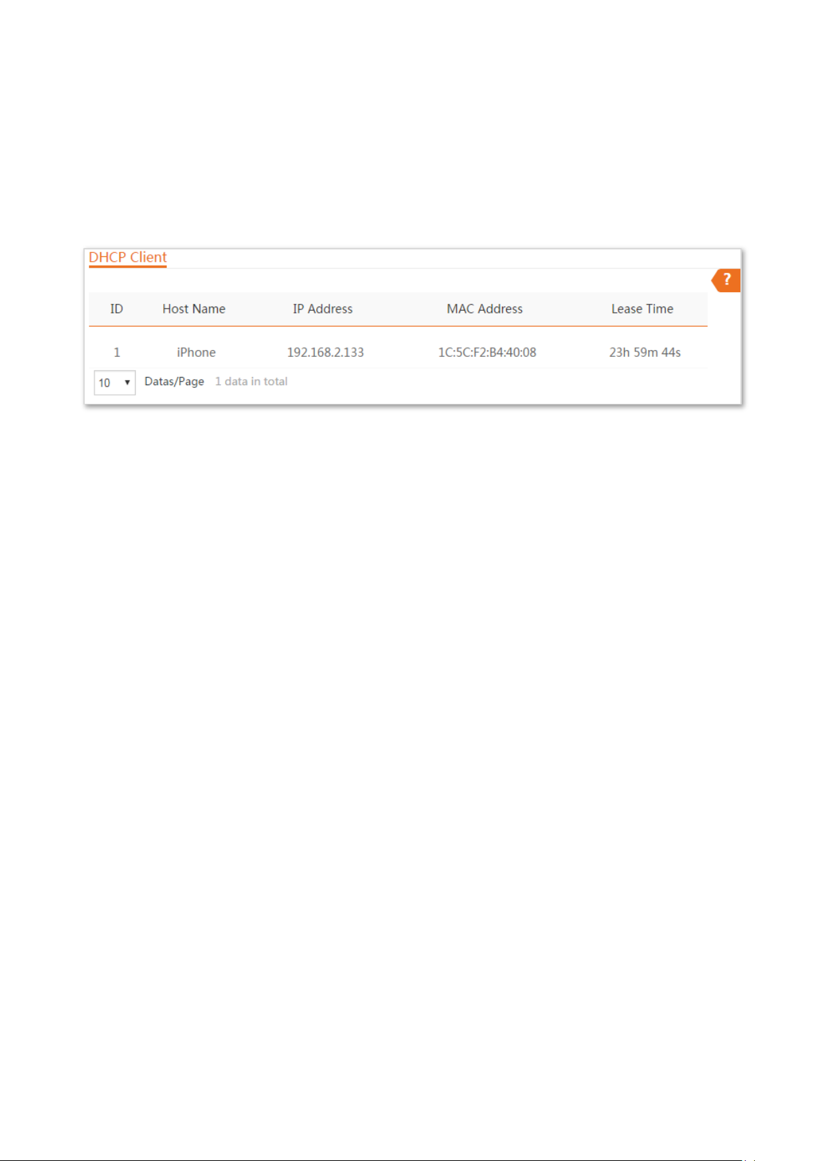
5.4 DHCP client
If the device functions as a DHCP server, you can view the DHCP client list to understand the details
about the clients that obtain IP addresses from the DHCP server. The details include host names, IP
addresses, MAC addresses, and lease time.
To access the page, choose Network > DHCP Client.
81
Page 89
Name
Description
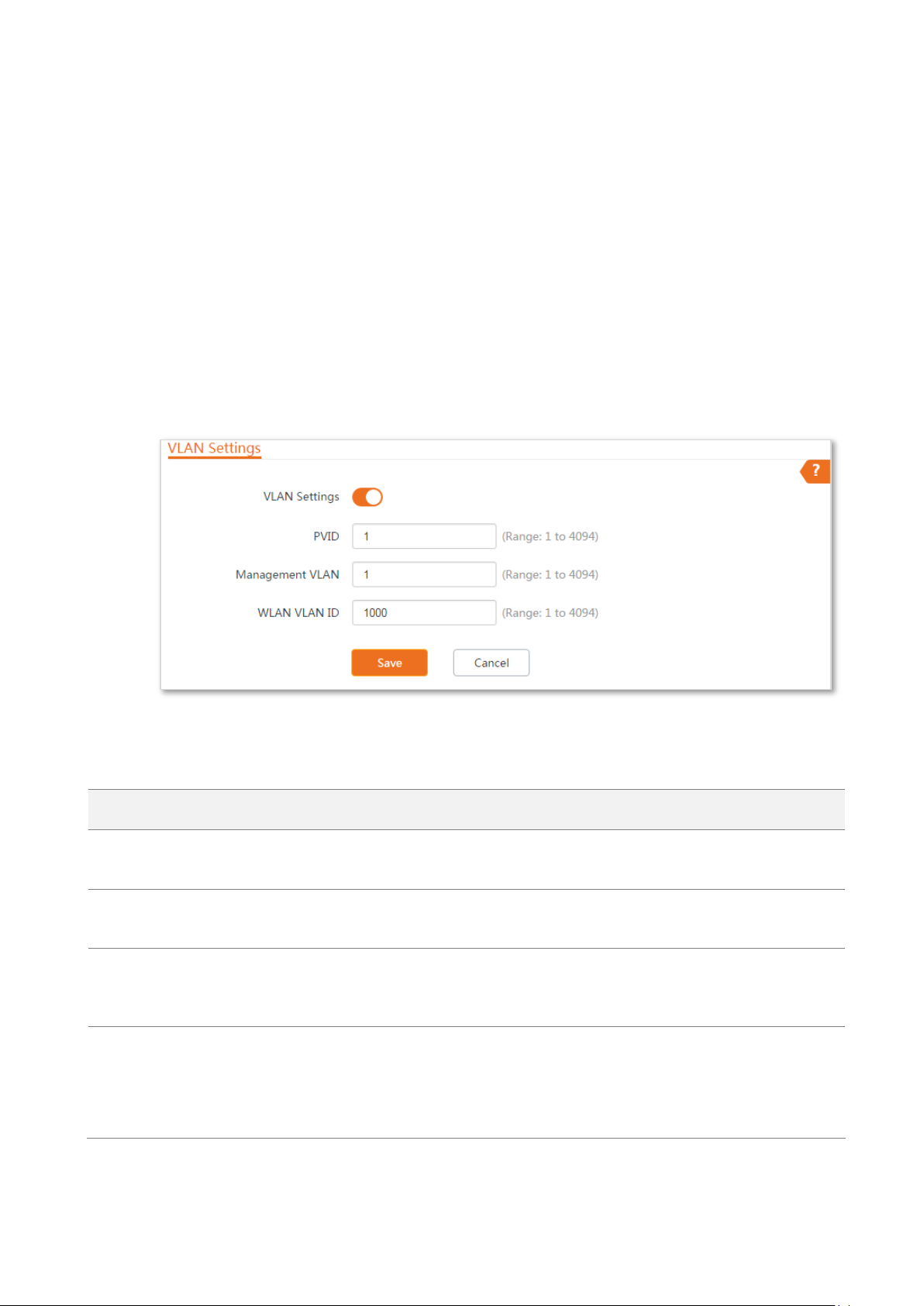
VLAN Settings
It specifies whether to enable the VLAN function of this device. By default, it is
disabled. After the VLAN function is enabled, the PoE/LAN port is used as trunk port.
PVID
It specifies the ID of the default native VLAN of the trunk port. The default ID is 1.
After the VLAN function is enabled, the PoE/LAN port is used as trunk port.
Management VLAN
It specifies the ID of the management VLAN of this device. The default ID is 1. After
changing the management VLAN, you can manage this device only after connecting
your computer to the new management VLAN.
WLAN VLAN ID
It allows you to set a VLAN ID for the wireless network of this device. By default, it is
set to 1000.
After the VLAN function is enabled, the WLAN interface functions as an access port,
whose PVID is the same as VLAN ID.
5.5 VLAN settings
5.5.1 Overview
The device supports the IEEE 802.1q VLAN function, so that it can be used in networks with QVLAN.
By default, the function is disabled.
5.5.2 Setting up VLAN
Step 1 Choose Network > VLAN Settings to enter the configuration page.
Step 2 Enable the function.
Step 3 Set the parameters as needed.
Step 4 Click Save.
----End
Parameters description
82
Page 90

Link Type of the
Port
Type of Received Packets
Transmitted Packets
Packet with Tag
Packet without Tag
Access
Forward the data to the
ports of the
corresponding VLAN
based on the VID in the
tag.
Forward the data to the
ports of the
corresponding VLAN
based on the PVID of
ports
Strip the tag in the packet and then
forward it
Trunk
VID PVID of the port, strip the tag
in the packet and then forward it
VID PVID of the port, retain the tag
in the packet and then forward it
CPE2: VLAN20
CPE1: VLAN10
Switch
Router
After the IEEE 802.1Q VLAN settings take effect, packet with tag will be forwards to the ports of the
corresponding VLAN according to the VID of the packet, and packet without tag will be forwards to
the ports of the corresponding VLAN according to the PVID of the port.
The following form shows the details about how different link type ports address received packets:
5.5.3 Example of configuring VLAN settings
Networking requirement
The devices connected to the same switch should belong to different VLANs.
Assumption:
CPE1 belongs to VLAN10, and CPE2 belongs to VLAN20.
Network Topology
83
Page 91

Ports of the Switch
VLAN ID (Allow the packets
belonging to the following VLANs
to access)
Type of Port
PVID
Uplink port (Connected
to a router)
1,10,20
Trunk
1
Port 1 (Connected to
CPE1)
1,10
Trunk
1
The connections of the switch:
The router is connected to the uplink port.
CPE1 is connected to port 1
CPE2 is connected to port 2
Configuration procedure
Step 1 Set up CPE1.
1. Log in to the web UI of CPE1, and choose Network > VLAN Settings.
2. Enable the function.
3. Set Management VLAN to 1.
4. Set WLAN VLAN ID to 10.
5. Click Save.
6. Click OK on the pop-up window, and wait until the CPE1 completes reboot.
Step 2 Set up CPE2 according to the steps in step 1.
Step 3 Set up the switch.
The following table shows the configuration on the switch:
84
Page 92

Port 2 (Connected to
CPE2)
1,20
Trunk
1
Port of the router is
connected to
VLAN ID (Allow the packets
belonging to the following VLANs
to access)
Type of Port
PVID
The switch
10, 20
Trunk
1
Keep the default settings for the parameters which are not mentioned here. Refer to the user
guide of the switch for details.
The following form shows the configuration on the router:
Refer to the user guide of the router for details.
----End
Verification
If the router enables two DHCP servers which belong to VLAN10 and VLAN20 respectively, the first
client connected to the CPE obtains an IP address and related parameters from the DHCP server
belonging to VLAN10, and the second client obtains these parameters from the DHCP sever
belonging to VLAN20.
85
Page 93

6 Wireless
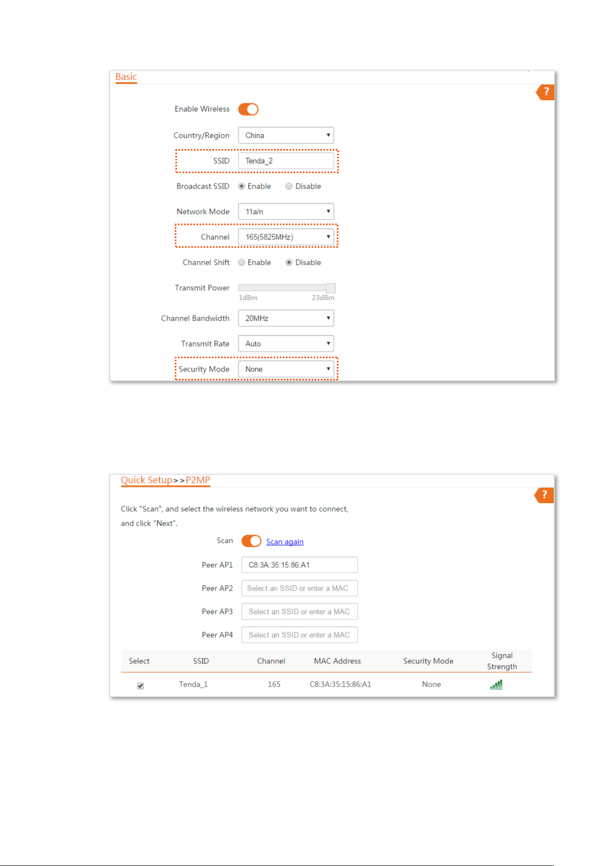
6.1 Basic
6.1.1 Overview
This module enables you to set basic wireless settings of the device, including SSID-related
parameters, network mode, channel, transmit power and so on.
6.1.2 Changing the basic settings
To change the basic settings of an SSID, perform the following procedure:
Step 1 Choose Wireless > Basic.
Step 2 Change the parameters as required. Generally, you only need to enable the wireless
function, and change SSID, Channel and Security Mode settings.
Step 3 Click Save.
86
Page 94

----End
Name
Description
Enable Wireless
It specifies whether to enable the wireless function. By default, it is enabled.
Country/Region
It specifies country or region where this device is located. You can select the country
or region to ensure that this device complies with the channel regulations of the
country or region.
SSID
It specifies the wireless network name.
Broadcast SSID
It specifies whether to broadcast the SSID.
When the device broadcasts an SSID, nearby wireless clients can detect the SSID.
When this parameter is set to Disable, the device does not broadcast the SSID and
nearby wireless clients cannot detect the SSID. In this case, you need to enter the
* * *
Parameters description
87
Page 95

Name
Description
SSID manually on your wireless client if you want to connect to the wireless network
corresponding to the SSID. This to some extent enhances the security of the wireless
network.
It is worth noting that after Broadcast SSID is set to Disable, a hacker can still
connect to the corresponding wireless network if he/she manages to obtain the SSID
by other means.
Network Mode
It specifies the wireless network mode of this device. The available options include
11a, 11n, and 11 a/n.
11a: It indicates that clients compliant with the 802.11a protocol can connect to the
device.
11n: It indicates that clients working at 5 GHz and compliant with 802.11n can
connect to the device.
11 a/n: It indicates that all clients working at 5 GHz and compliant with the 802.11a
or 802.11n protocol can connect to the device.
Channel
It specifies channel in which this device operates. Auto indicates that this device
automatically changes to a channel rarely used in the ambient environment to
prevent interference.
Channel Shift
It specifies the shift of the channel center frequency. With this function enabled, the
channel center frequency shifts 5 MHz based on the frequency defined by the IEEE
802.11 standard, so that the device can exchange data on less interference channels.
Transmit Power
It specifies the transmit power of this device.
Higher number indicates wider WiFi coverage. Setting a proper transmit power helps
improve the performance and security of the wireless network.
Channel Bandwidth
It specifies the bandwidth of the operating channel of a wireless network. Change
the default setting only when necessary.
10MHz: It indicates that the channel bandwidth of the device is 10 MHz.
20MHz: It indicates that the channel bandwidth of the device is 20 MHz.
30MHz: It indicates that the channel bandwidth of the device is 30 MHz.
40MHz: It indicates that the channel bandwidth of the device is 40 MHz.
Auto: It specifies that the device can switch its channel bandwidth among 10MHz,
20 MHz, 30MHz and 40 MHz based on the ambient environment.
Transmit Rate
It specifies wireless transmission rate of the device.
When the channel bandwidth is set to 10 MHz, the rate automatically reduces, and
the maximum rate is 72.2 Mbps.
When the channel bandwidth is set to 20 MHz, the rate automatically reduces, and
the maximum rate is 144.4 Mbps.
When the channel bandwidth is set to 30 MHz, the rate automatically reduces, and
the maximum rate is 216.6 Mbps.
88
Page 96

Name
Description
When the channel bandwidth is set to 40 MHz, the maximum rate is 300 Mbps.
When the channel bandwidth is set to Auto, the maximum rate is 300 Mbps.
Security Mode
A wireless network uses radio, which is open to the public, as its data transmission
medium. If the wireless network is not protected by necessary measures, any client
can connect to the network to use the resources of the network or access
unprotected data over the network. To ensure communication security,
transmission links of wireless networks must be encrypted for protection.
The device supports various security modes for network encryption, including None,
WEP, WPA-PSK, WPA2-PSK, Mixed WPA/WPA2-PSK, WPA, and WPA2.
None: It indicates that any wireless client can connect to the wireless network. This
option is not recommended because it affects network security.
WEP: It uses a static key to encrypt all exchanged data, and ensures that a wireless
LAN has the same level of security as a wired LAN. Data encrypted based on WEP
can be easily cracked. In addition, WEP supports a maximum wireless network
throughput of only 54 Mbps. Therefore, this security mode is not recommended.
WPA-PSK/WPA2-PSK/Mixed WPA/WPA2-PSK: They belong to pre-shared key or
personal key modes, where Mixed WPA/WPA2-PSK supports both WPA-PSK and
WPA2-PSK.
WPA-PSK, WPA2-PSK, and Mixed WPA/WPA2-PSK adopt a pre-shared key for
authentication, while the AP generates another key for data encryption. This
prevents the vulnerability caused by static WEP keys, and makes the three security
modes suitable for ensuring security of home wireless networks. Nevertheless,
because the initial pre-shared key for authentication is manually set and all clients
use the same key to connect to the same AP, the key may be disclosed
unexpectedly. This makes the security modes not suitable for scenarios where high
security is required.
To address the key management weakness of WPA-PSK and WPA2-PSK, the WiFi
Alliance puts forward WPA and WPA2, which use 802.1x to authenticate clients and
generate data encryption–oriented root keys. WPA and WPA2 use the root keys to
replace the pre-shared keys that set manually, but adopt the same encryption
process as WPA-PSK and WPA2-PSK.
WPA/WPA2: WPA and WPA2 uses 802.1x to authenticate clients and the login
information of a client is managed by the client. This effectively reduces the
probability of information leakage. In addition, each time a client connects to an AP
that adopts the WPA or WPA2 security mode, the RADIUS server generates a data
encryption key and assigns it to the client. This makes it difficult for attackers to
obtain the key. These features of WPA and WPA2 help significantly increase network
security, making WPA and WPA2 the preferred security modes of wireless networks
that require high security.
Encryption Algorithm
It specifies the encryption algorithm corresponding to the selected security mode. If
Security Mode is set to WPA-PSK, this parameter has the AES and TKIP values. If
Security Mode is set to WPA2-PSK or Mixed WPA/WPA2-PSK, this parameter has the
AES, TKIP, and TKIP&AES values.
AES: It indicates the Advanced Encryption Standard.
TKIP: It indicates the Temporal Key Integrity Protocol. If TKIP is used, the maximum
89
Page 97
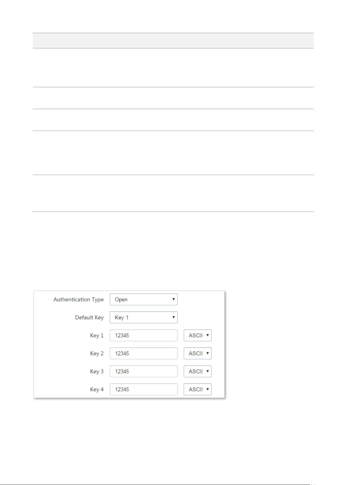
Name
Description
wireless throughput of the AP is limited to 54 Mbps.
TKIP&AES: It indicates that both TKIP and AES encryption algorithms are supported.
Wireless clients can connect to the wireless network corresponding to the selected
SSID using TKIP or AES.
Key
It specifies a pre-shared WPA key. It consists of 8 to 63 ASCII characters or 8 to 64
hexadecimal characters.
Key Update Interval
It specifies interval at which a WPA key is updated. A shorter interval leads to higher
security. The value 0 indicates that no key update is performed.
Isolate Client
This parameter implements a function similar to the VLAN function for wired
networks. It isolates the wireless clients connected to the same wireless network
corresponding to an SSID, so that the wireless clients can access only the wired
network connected to the device. Applying this function to hotspot setup at public
places such as hotels and airports helps increase network security.
Max. Number of Clients
This parameter specifies the maximum number of clients that can connect to the
wireless network corresponding to an SSID. If the number is reached, the wireless
network rejects new connection requests from clients. This limit helps balance load
among devices.
None
It indicates that any wireless client can connect to the wireless network. Choose this option only
when necessary.
WEP
Parameters description
90
Page 98

Name
Description
Authentication Type
It specifies the authentication type for the WEP security mode. The options include
Open and Shared. The options share the same encryption process.
Open: It specifies that authentication is not required and data exchanged is encrypted
using WEP. In this case, a wireless client can connect to the wireless network
corresponding to the selected SSID without being authenticated, and the data
exchanged between the client and the network is encrypted in WEP security mode.
Shared: It specifies that a shared key is used for authentication and data exchanged is
encrypted using WEP. In this case, a wireless client must use a preset WEP key to
connect to the wireless network corresponding to the selected SSID. The wireless
client can be connected to the wireless network only if they use the same WEP key.
Default Key
It specifies the WEP key for the Open or Shared encryption type.
For example, if Default Key is set to Security Key 2, a wireless client can connect to the
wireless network corresponding to the selected SSID only with the password specified
by Security Key 2.
Key 1/2/3/4
Enter WEP key. You can enter four keys, but only the key specified in the Default Key
takes effect.
ASCII
It indicates that a key selected for the Open or Shared authentication type contains
hexadecimal characters.
5 or 13 ASCII characters are allowed in the key.
Hex
It indicates that a key selected for the Open or Shared authentication type contains
hexadecimal characters.
10 or 26 hexadecimal characters (range: 0-9, a-f, and A-F) are allowed in the key.
WPA-PSK, WPA2-PSK, and Mixed WPA/WPA2-PSK
91
Page 99
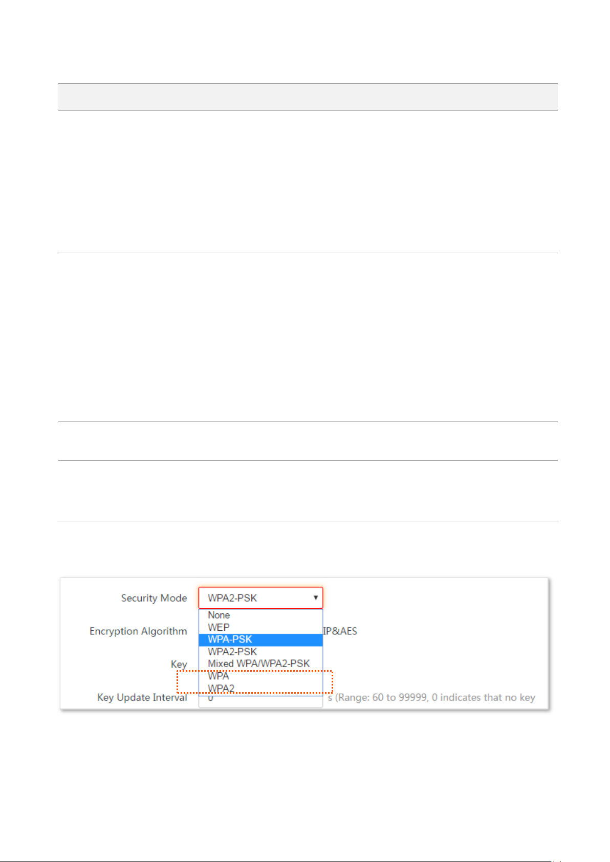
Parameters description
Name
Description
Security Mode
It indicates the personal or pre-shared key security mode, including WPA-PSK,
WPA2-PSK, and Mixed WPA/WPA2-PSK.
WPA-PSK: It indicates that the wireless network corresponding to the selected SSID
is encrypted using WPA-PSK.
WPA2-PSK: It indicates that the wireless network corresponding to the selected SSID
is encrypted using WPA2-PSK.
Mixed WPA/WPA2-PSK: It indicates that wireless clients can connect to the wireless
network corresponding to the selected SSID using either WPA-PSK or WPA2-PSK.
Encryption Algorithm
It specifies the encryption algorithm corresponding to the selected security mode. If
Security Mode is set to WPA-PSK, this parameter has the AES and TKIP values. If
Security Mode is set to WPA2-PSK or Mixed WPA/WPA2-PSK, this parameter has the
AES, TKIP, and TKIP&AES values.
AES: It indicates the Advanced Encryption Standard.
TKIP: It indicates the Temporal Key Integrity Protocol. If TKIP is used, the maximum
wireless throughput of the AP is limited to 54 Mbps.
TKIP&AES: It indicates that both TKIP and AES encryption algorithms are supported.
Wireless clients can connect to the wireless network corresponding to the selected
SSID using TKIP or AES.
Key
It specifies a pre-shared WPA key. A WPA key can contain 8 to 63 ASCII characters or
8 to 64 hexadecimal characters.
Key Update Interval
It specifies the automatic update interval of a WPA key for data encryption. A
shorter interval results in higher data security.
The value 0 indicates that a WAP key is not updated.
WPA and WPA2
92
Page 100

Parameters description
Name
Description
Security Mode
The WPA and WPA2 options are available for network protection with a RADIUS
server.
WPA: It indicates that the wireless network corresponding to the selected SSID is
encrypted using WPA.
WPA: It indicates that the wireless network corresponding to the selected SSID is
encrypted using WPA.
RADIUS Server
It specifies the IP address of the RADIUS server for client authentication.
RADIUS Port
It specifies the port number of the RADIUS server for client authentication.
RADIUS Password
It specifies the shared password of the RADIUS server.
Encryption Algorithm
It specifies the encryption algorithm corresponding to the selected security mode.
The available options include AES, TKIP, and TKIP&AES.
AES: It indicates the Advanced Encryption Standard.
TKIP: It indicates the Temporal Key Integrity Protocol.
TKIP&AES: It indicates that both TKIP and AES encryption algorithms are supported.
Wireless clients can connect to the wireless network corresponding to the selected
SSID using TKIP or AES.
Key Update Interval
It specifies the automatic update interval of a WPA key for data encryption. A
shorter interval results in higher data security.
The value 0 indicates that a WAP key is not updated.
93
 Loading...