

Page 1

i12 Wireless Access Point
User Guide
Q1.
Page 2

Copyright Statement
© 2017 Shenzhen Tenda Technology Co., Ltd. All rights reserved.
is a registered trademark legally held by Shenzhen Tenda Technology Co., Ltd. Other brand and
product names mentioned herein are trademarks or registered trademarks of their respective holders. Copyright
of the whole product as integration, including its accessories and software, belongs to Shenzhen Tenda
Technology Co., Ltd. No part of this publication can be reproduced, transmitted, transcribed, stored in a retrieval
system, or translated into any language in any form or by any means without the prior written permission of
Shenzhen Tenda Technology Co., Ltd.
Disclaimer
Pictures, images and product specifications herein are for references only. To improve internal design,
operational function, and/or reliability, Tenda reserves the right to make changes to the products without
obligation to notify any person or organization of such revisions or changes. Tenda does not assume any liability
that may occur due to the use or application of the product described herein. Every effort has been made in the
preparation of this document to ensure accuracy of the contents, but all statements, information and
recommendations in this document do not constitute a warranty of any kind, express or implied.
Page 3
Item
Presentation
Example
Cascading menus
>
System > Live Users
Parameter and value
Bold
Set User Name to Tom.
Variable
Italic
Format: XX:XX:XX:XX:XX:XX
UI control
Bold
On the Policy page, click the OK button.
Message
“ ”
The “Success” message appears.
Symbol
Meaning
This format is used to highlight information of importance or special interest. Ignoring this
type of note may result in ineffective configurations, loss of data or damage to device.
This format is used to highlight a procedure that will save time or resources.
Acronym or Abbreviation
Full Spelling
AP
Access Point
DDNS
Dynamic Domain Name System
DHCP
Dynamic Host Configuration Protocol
DLNA
Digital Living Network Alliance
DMZ
Demilitarized Zone
DNS
Domain Name System
IPTV
Internet Protocol Television
ISP
Internet Service Provider
L2TP
Layer 2 Tunneling Protocol
Preface
Thank you for choosing Tenda! Please read this user guide before you start with i12.
Conventions
The typographical elements that may be found in this document are defined as follows.
The symbols that may be found in this document are defined as follows.
Acronyms and Abbreviations
Page 4
Acronym or Abbreviation
Full Spelling
MPPE
Microsoft Point-to-Point Encryption
PPP
Point To Point Protocol
PPPoE
Point-to-Point Protocol over Ethernet
PPTP
Point to Point Tunneling Protocol
SSID
Service Set Identifier
STB
Set Top Box
URL
Uniform Resource Locator
VLAN
Virtual Local Area Network
VPN
Virtual Private Network
WISP
Wireless Internet Service Provider
WPS
WiFi Protected Setup
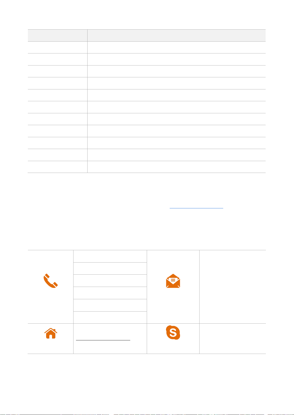
Hotline
Global: (86) 755-27657180
Email
support@tenda.cn
United States: 1-800-570-5892
Canada: 1-888-998-8966
Hong Kong: 00852-81931998
Australia: 1300787922
New Zealand: 800787922
Website
http://www.tendacn.com
Skype
tendasz
Additional Information
For more information, search this product model on our website at http://www.tendacn.com.
Technical Support
If you need more help, contact us by any of the following means. We will be glad to assist you as soon as
possible.
Page 5

Contents
1 Get to Know Your Device ................................................................................................................................... 7
1.1 Overview ...................................................................................................................................................... 7
1.2 Packing List ................................................................................................................................................... 7
1.3 Appearance .................................................................................................................................................. 8
1.3.1 LED Indicator ..................................................................................................................................... 8
1.3.2 Button and Port................................................................................................................................. 8
1.3.3 Label .................................................................................................................................................. 9
2 Installing the AP ............................................................................................................................................... 11
2.1 Preparing for Installation ........................................................................................................................... 11
2.1.1 Precautions ..................................................................................................................................... 11
2.1.2 Preparing Tools ............................................................................................................................... 11
2.2 Installing the AP ......................................................................................................................................... 11
2.3 Connecting the Power Supply .................................................................................................................... 15
2.4 Connecting the AP ..................................................................................................................................... 16
3 Managing the AP.............................................................................................................................................. 18
3.1 Management Modes ................................................................................................................................. 18
3.2 Logging In to the Web UI of the AP ............................................................................................................ 18
3.3 Logging Out of the Web UI of the AP ......................................................................................................... 20
3.4 Common Buttons on the Web UI ............................................................................................................... 21
4 Functions ......................................................................................................................................................... 22
4.1 Status ......................................................................................................................................................... 22
4.1.1 System Status .................................................................................................................................. 22
4.1.2 Wireless Status ................................................................................................................................ 22
4.1.3 Traffic Statistics ............................................................................................................................... 23
4.1.4 Client List ......................................................................................................................................... 24
4.2 Quick Setup ................................................................................................................................................ 25
4.2.1 AP Mode ......................................................................................................................................... 26
Page 6

4.2.2 WDS Mode ...................................................................................................................................... 26
4.2.3 AP+Client Mode .............................................................................................................................. 33
4.3 Network Settings ....................................................................................................................................... 35
4.3.1 LAN Setup ....................................................................................................................................... 35
4.3.2 DHCP Server .................................................................................................................................... 38
4.4 Wireless Settings ........................................................................................................................................ 40
4.4.1 Basic Settings .................................................................................................................................. 40
4.4.2 Radio Settings ................................................................................................................................. 49
4.4.3 Channel Scan ................................................................................................................................... 50
4.4.4 Advanced Settings ........................................................................................................................... 52
4.4.5 Access Control ................................................................................................................................. 54
4.4.6 QVLAN Settings ............................................................................................................................... 56
4.5 SNMP ......................................................................................................................................................... 60
4.6 Tools ........................................................................................................................................................... 61
4.6.1 Firmware Upgrade .......................................................................................................................... 61
4.6.2 Date & Time .................................................................................................................................... 62
4.6.3 Logs ................................................................................................................................................. 65
4.6.4 Configuration Management ............................................................................................................ 68
4.6.5 Accounts ......................................................................................................................................... 71
4.6.6 Diagnostics ...................................................................................................................................... 73
4.6.7 Reboot............................................................................................................................................. 73
4.6.8 LED Control ..................................................................................................................................... 76
Appendixes .............................................................................................................................................................. 77
Page 7

Model
Product Name
Power Supply
DC
PoE
i12
Wireless access point (25
clients)
12V 1A
IEEE 802.3at PoE
Ceiling-mounted AP
Mounting bracket
Ethernet cable
Installation guide
Screw x 4
Sleeve anchor x 4
1 Get to Know Your Device
1.1 Overview
i12 is a Tenda ceiling-mounted wireless access point (AP) that offers a wireless transmission capacity of up to 300
Mbps. It supports DC and PoE power supplies, and can be managed using the web UI of the AP or a Tenda AP
controller (AC) such as M3. The AP is an optimum choice for providing wireless coverage in indoor areas such as
enterprises, hotels, and restaurants.
The following table provides the specifications of i12.
1.2 Packing List
Page 8
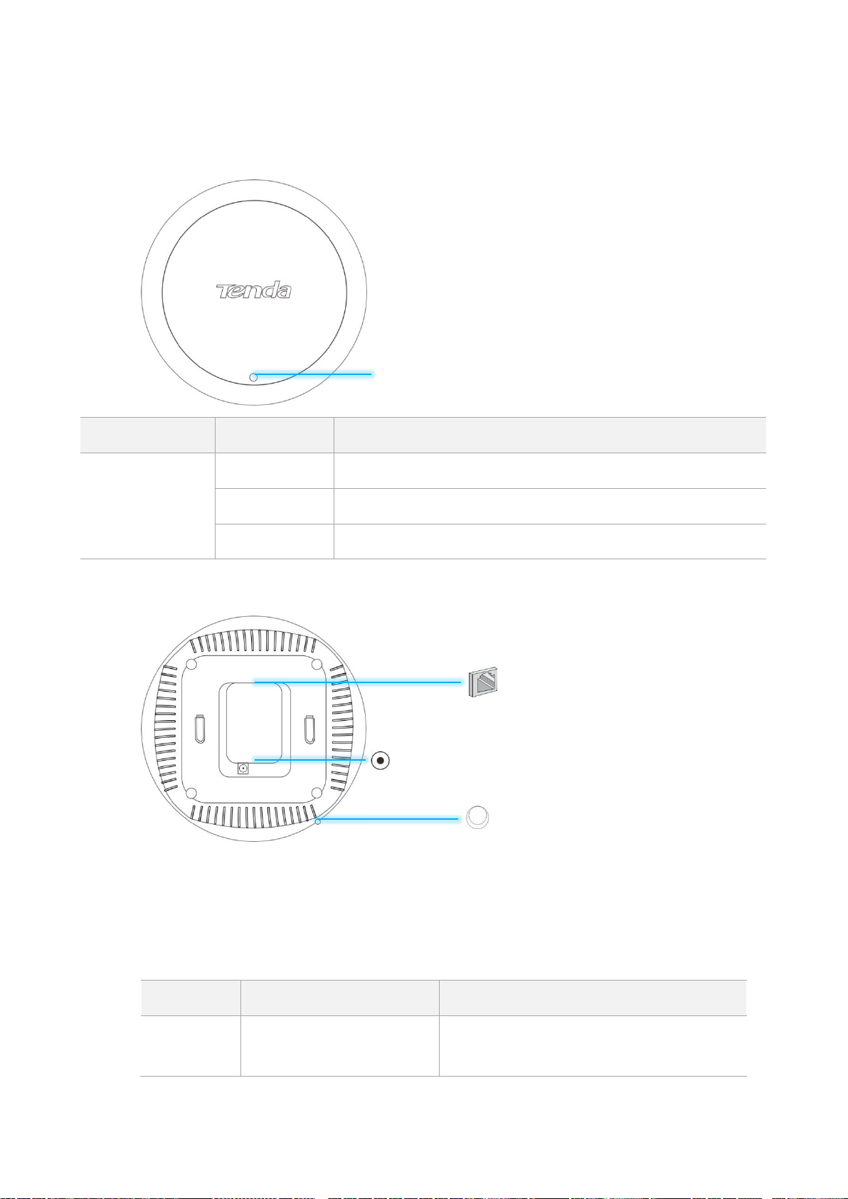
1.3 Appearance
LED Indicator
Status
Description
System indicator
Solid on
The system is booting or faulty.
Blinking
The system is running properly.
Off
The system is powered off or the LED indicator is turned off.
Model
Rate
Connection Description
i12
10/100/1000 Mbps auto
negotiation
If the AP is powered using a DC adapter,
connect this port to a switch. If the AP must be
powered through PoE, connect this port to an
1.3.1 LED Indicator
System indicator
1.3.2 Button and Port
Reset button
After the AP is powered on, you can hold down this button for 8 seconds to restore the factory
settings.
RJ45 port
This port is used to connect to a PoE power supply and exchange data.
RJ45 port
Power jack
Reset button
Page 9

Model
Rate
Connection Description
IEEE 802.3at PoE switch.
The AP allows a PoE power supply distance of
not longer than 100 meters.
Model
Power Specifications
Input
Output
i12
100V-240V, 50/60Hz AC
12V 1A DC
Position of the label
(1)
(3)
(4)
(5)
(6)
(2)
Power jack
The power jack is used to connect to a DC adapter for supplying power to the AP.
1.3.3 Label
The label is located on the rear panel of the AP. For details of the label, see the following figure.
(1): Name of the AP.
(2): Model of the AP.
Page 10

(3): Default IP address of the AP. You can use this IP address to log in to the web UI of the AP.
(4): Default user name and password of the web UI of the AP.
(5): MAC address of the AP. The default primary SSID of the AP is Tenda_XXXXXX, where XXXXXX
indicates the last 6 characters of this MAC address.
(6): Serial number of the AP. If the AP is faulty, you need to provide this serial number when sending
the AP for repair.
Page 11

Environment
Temperature
Humidity
Operating
environment
0°C - 45°C
10%RH - 90%RH (non-condensing)
Storage environment
-40°C - 70°C
5%RH - 90%RH (non-condensing)
Rubber hammer
Marker
Hammer drill
Spirit level
Measuring tape
6 mm drill bit
Phillips screwdriver
ESD gloves
Ladder
2 Installing the AP
2.1 Preparing for Installation
Before installing the AP, follow the instructions in this section to make preparation.
2.1.1 Precautions
To prevent damaging the AP or causing a personal injury, pay attention to the following precautions:
Ensure that the temperature and humidity requirements specified in the following table are met.
Ensure that the AP is mounted on a place free of accumulated water and water drips. Do not install the
AP in a wet environment.
Do not open or remove the housing of the AP.
Keep the AP clean.
Before cleaning the AP, disconnect it from the power supply. Do not scrub the AP with any liquid.
2.1.2 Preparing Tools
You may need a rubber hammer, a marker, a hammer drill, a spirit level, a measuring tape, a 6 mm drill bit, a
Phillips screwdriver, ESD gloves, and a ladder during installation. Prepare them yourself.
2.2 Installing the AP
Step 1 Place the mounting bracket onto the target position of the ceiling and mark the positions of the screw
Page 12
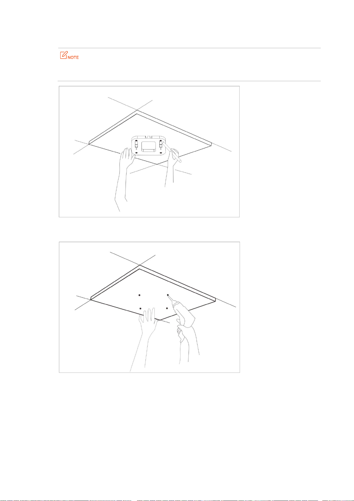
holes.
If the AP is powered using a DC adapter, a receptacle must be available within 1 meter from the
mounting position on the ceiling.
Step 2 Create holes in the marked positions. Each hole measures at 6 mm in diameter and 25 mm to 30 mm in
depth.
Step 3 Use the rubber hammer to knock the sleeve anchors into the holes.
Page 13

Step 4 Place the Ethernet cable (CAT5 or better cable) to be connected to the AP into the cable tray. If you use
a DC adapter to supply power to the AP, place the power cable into the cable tray as well.
Step 5 Lead the screws through the screw holes of the mounting bracket into the sleeve anchors and use the
Phillips screwdriver to fasten the screws.
Page 14

Step 6 Connect the Ethernet cable to the RJ45 port. If you use a DC adapter to supply power to the AP,
connect the power cable to the power jack of the AP.
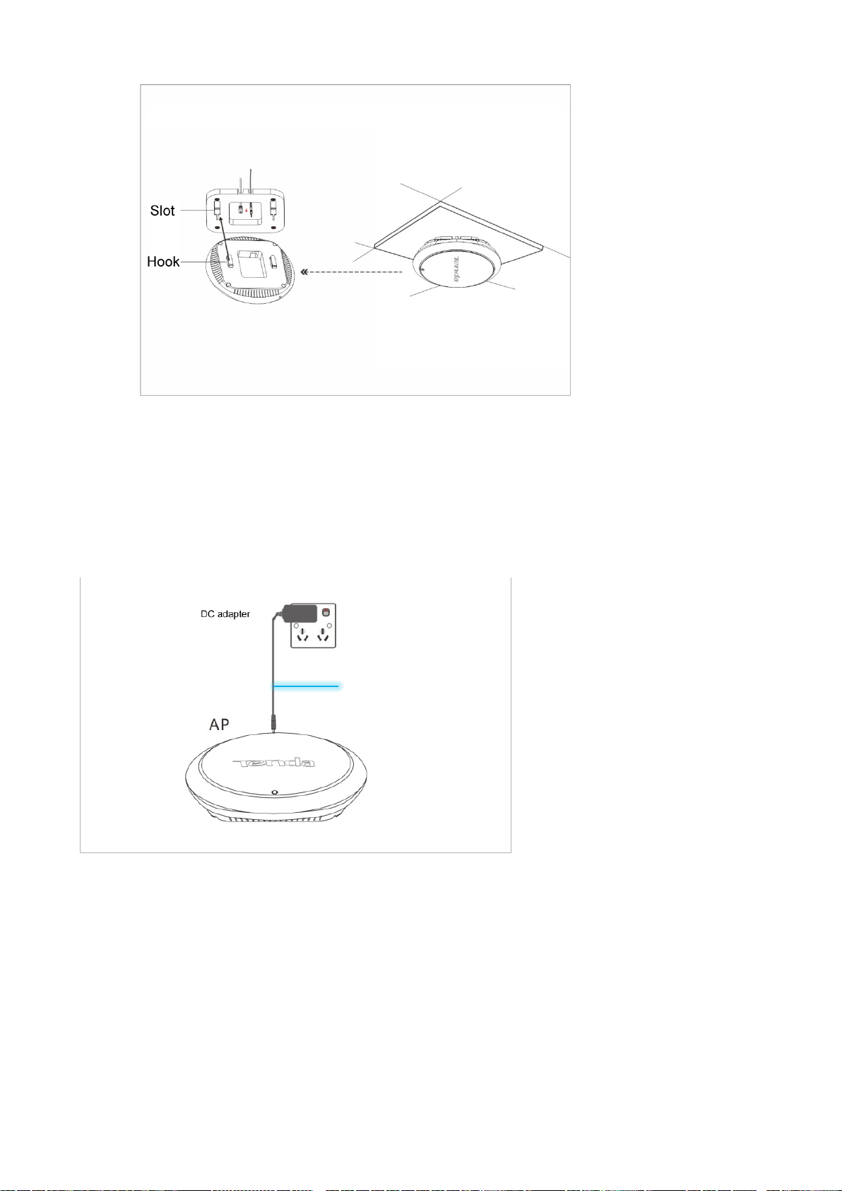
Step 7 Insert the hooks of the AP inside the slots of the mounting bracket to fix the AP onto the mounting
bracket.
Page 15
---End
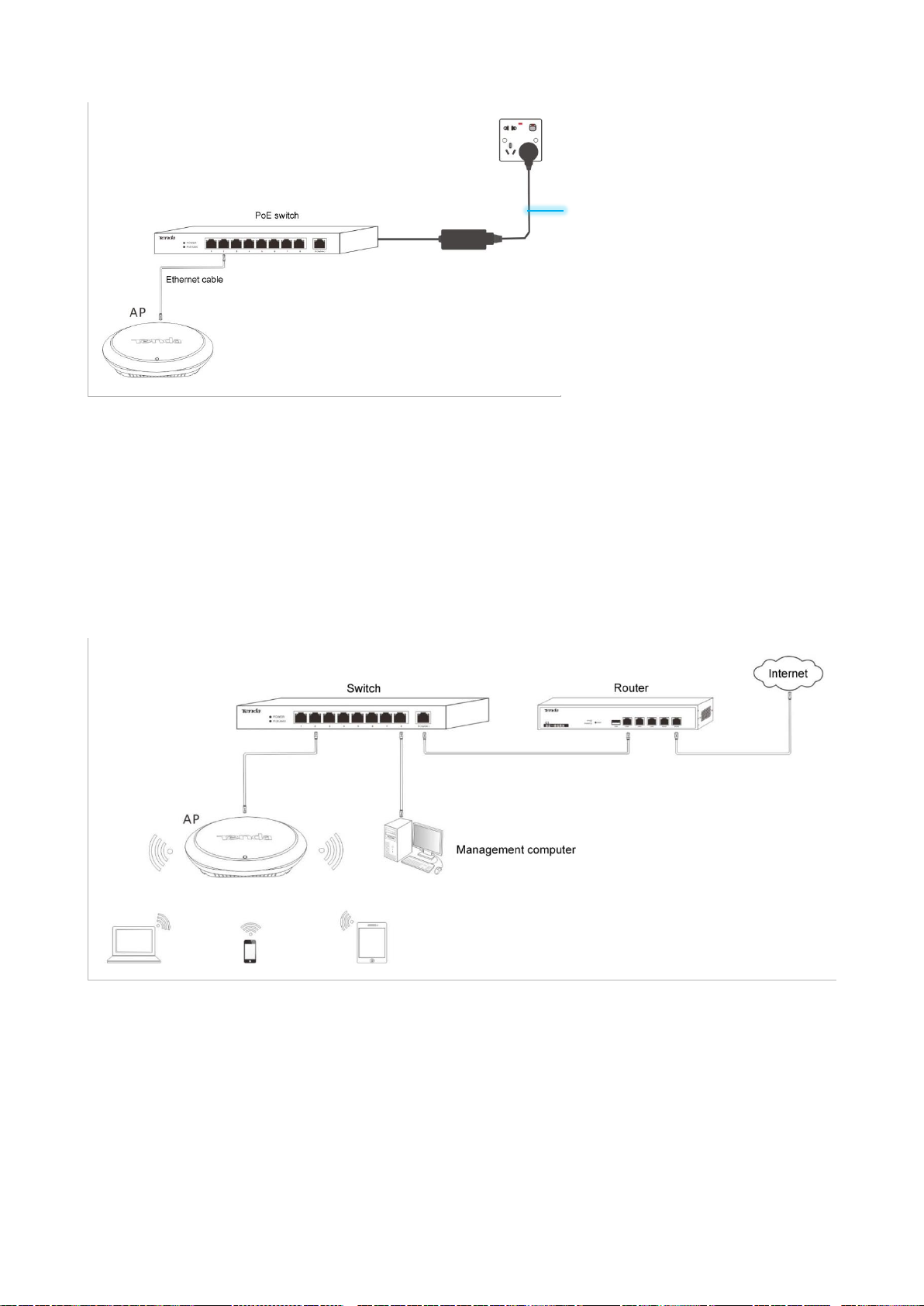
2.3 Connecting the Power Supply
The AP can be powered using the DC adapter accompanying the AP or a piece of IEEE 802.3at PoE power supply
equipment.
DC input: 12V 1A
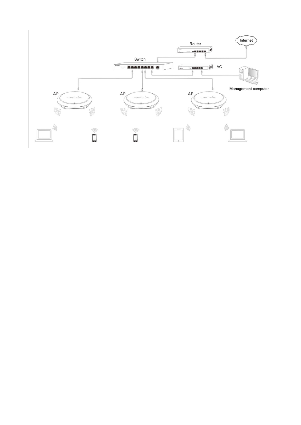
If you power the AP through PoE, connect the Ethernet cable (≤ 100 meters) connected to the RJ45 port of the
AP to an IEEE 802.3at PoE switch.
Page 16
IEEE 802.3at PoE power supply
After the AP is connected to a power supply, it initializes. During initialization, the LED indicator turns solid on for
5 to 7 seconds, and then blinks. When the indicator blinks, the AP is working properly.
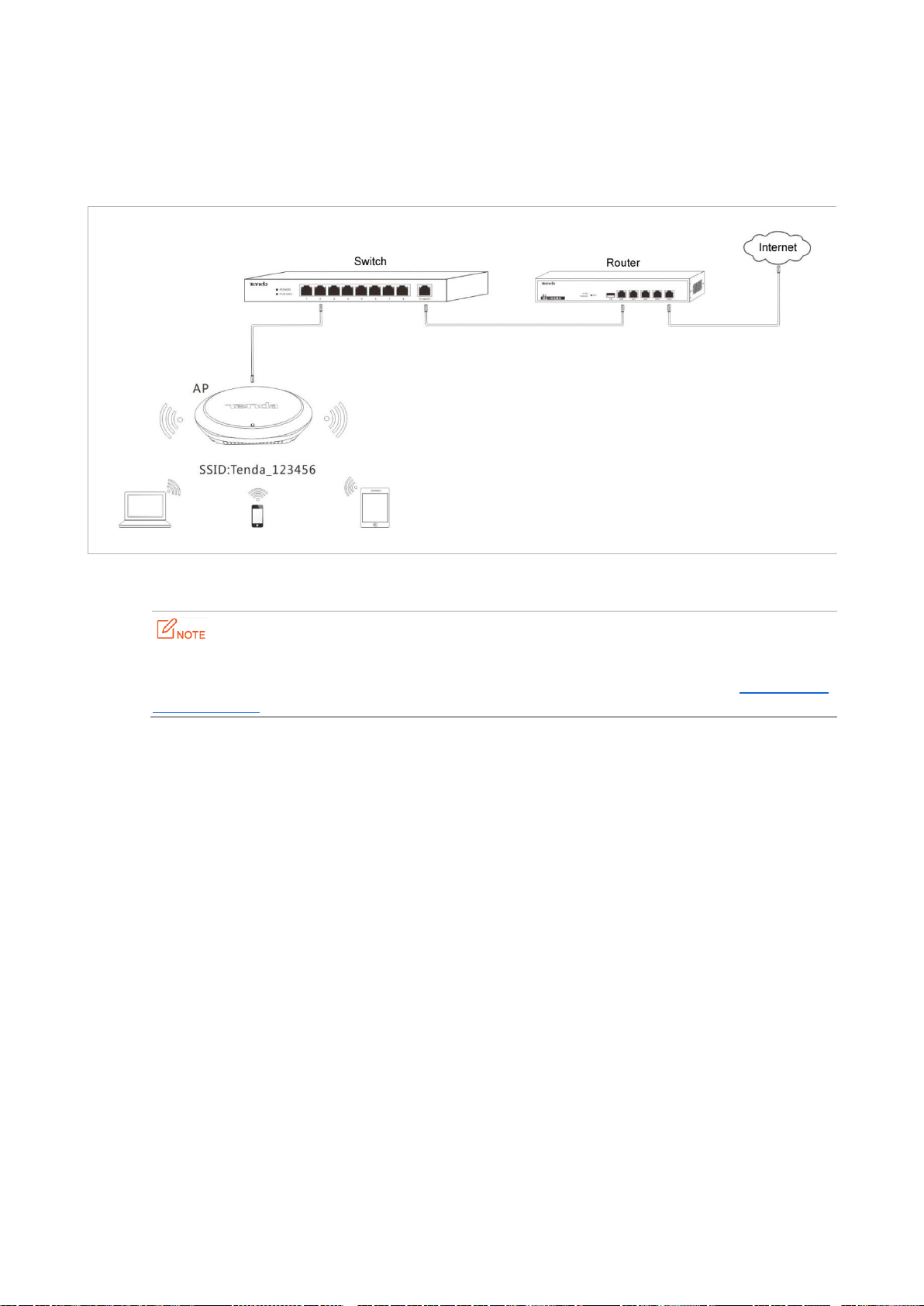
2.4 Connecting the AP
If you need to install only a small number of APs, connect the APs using the following topology, which allows you
to log in to the web UI of each AP to manage the AP.
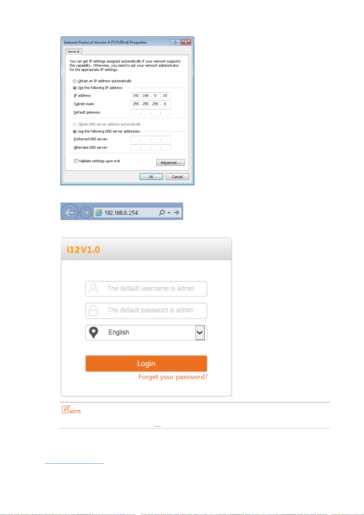
If you need to install a large number of APs, connect the APs to an M3 (Tenda AC) using the following topology so
that you can manage all the APs in a centralized manner.
Page 17
Page 18

Parameter
Default Value
IP address
192.168.0.254
User name
admin
Password
admin
3 Managing the AP
3.1 Management Modes
The AP can be managed on the web UI of the AP or using M3 (Tenda AC).
When the AP is connected to a network with M3, the AC automatically detects the AP. The AP can be used
without being configured. You can log in to the web UI of the AC to manage the AP.
You can download the user guide for M3 from http://www.tendacn.com.
The following sections describe how to log in to the web UI of the AP to manage the AP.
3.2 Logging In to the Web UI of the AP
You can use a web browser to log in to the web UI of the AP. The following table provides default login
information of the AP.
Procedure for logging in to the web UI using the default login information:
Step 1 Set IP address of your local area connection to 192.168.0.X (X: 2 - 253) and Subnet mask to
255.255.255.0.
Page 19
Step 2 Access 192.168.0.254 using a web browser.
Step 3 Enter admin as the user name and password and click Login.
If this page is not displayed, refer to Q1 in Appendix A "FAQ."
---End
You can view and modify the configuration of the AP on the web UI. For details about how to configure the AP,
see Chapter 4 "Functions."
Page 20

3.3 Logging Out of the Web UI of the AP
After you log in to the web UI of the AP, the system logs you out if you perform no operation on the web UI
within the client timeout interval. (The default interval is 5 minutes and can be changed.)
When you close the web browser, the system logs you out as well.
When you are logged out, the system does not save the current configuration. Therefore, it is recommended that
you save the current configuration before logging out.
If you close the web browser tab page used to log in to the web UI of the AP instead of the web
browser, you are not logged out.
Web UI Layout
The web UI is composed of three parts, including the level-1 and level-2 navigation bar, level-3 navigation bar,
and configuration area. See the following figure.
The functions and parameters dimmed on the web UI indicates that they are not supported by the AP
or cannot be changed in the current configuration.
Page 21
No.
Name
Description
1
Level-1 and level-2 navigation
bar
The navigation bars display the function menu of the AP. When
you select a function in navigation bar, the configuration of the
function appears in the configuration area.
2
Level-3 navigation bar
3
Configuration area
It enables you to view and modify configuration.
Button
Description
Refresh
It is used to update the content of the current page.
Save
It is used to save the configuration on the current page and enable the configuration to
take effect.
Restore
It is used to change the current configuration on the current page back to the original
configuration.
Help
It is used to view help information corresponding to the settings on the current page.
1
2
3
3.4 Common Buttons on the Web UI
Description of common buttons
Page 22
4 Functions
4.1 Status
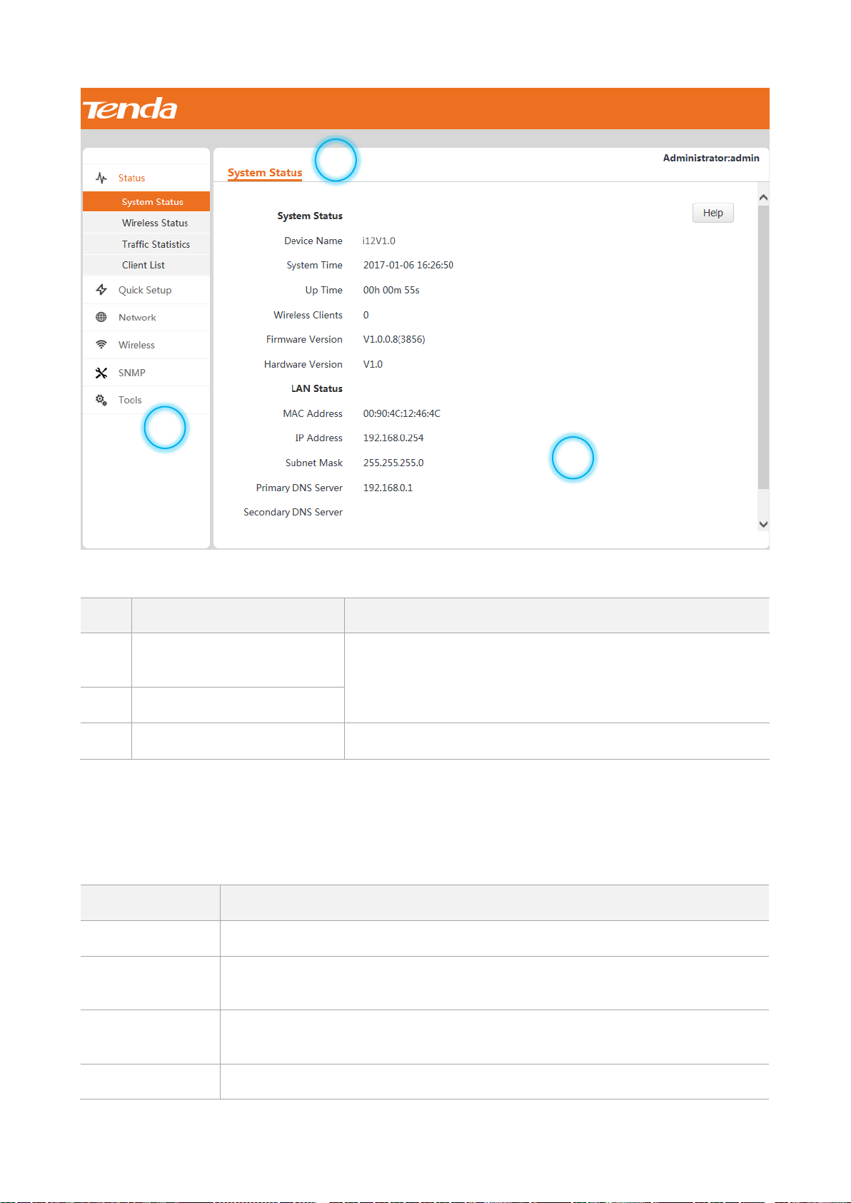
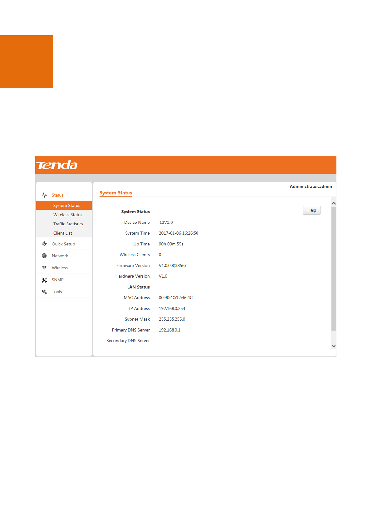
4.1.1 System Status
To view the system status and LAN status of the AP, choose Status > System Status.
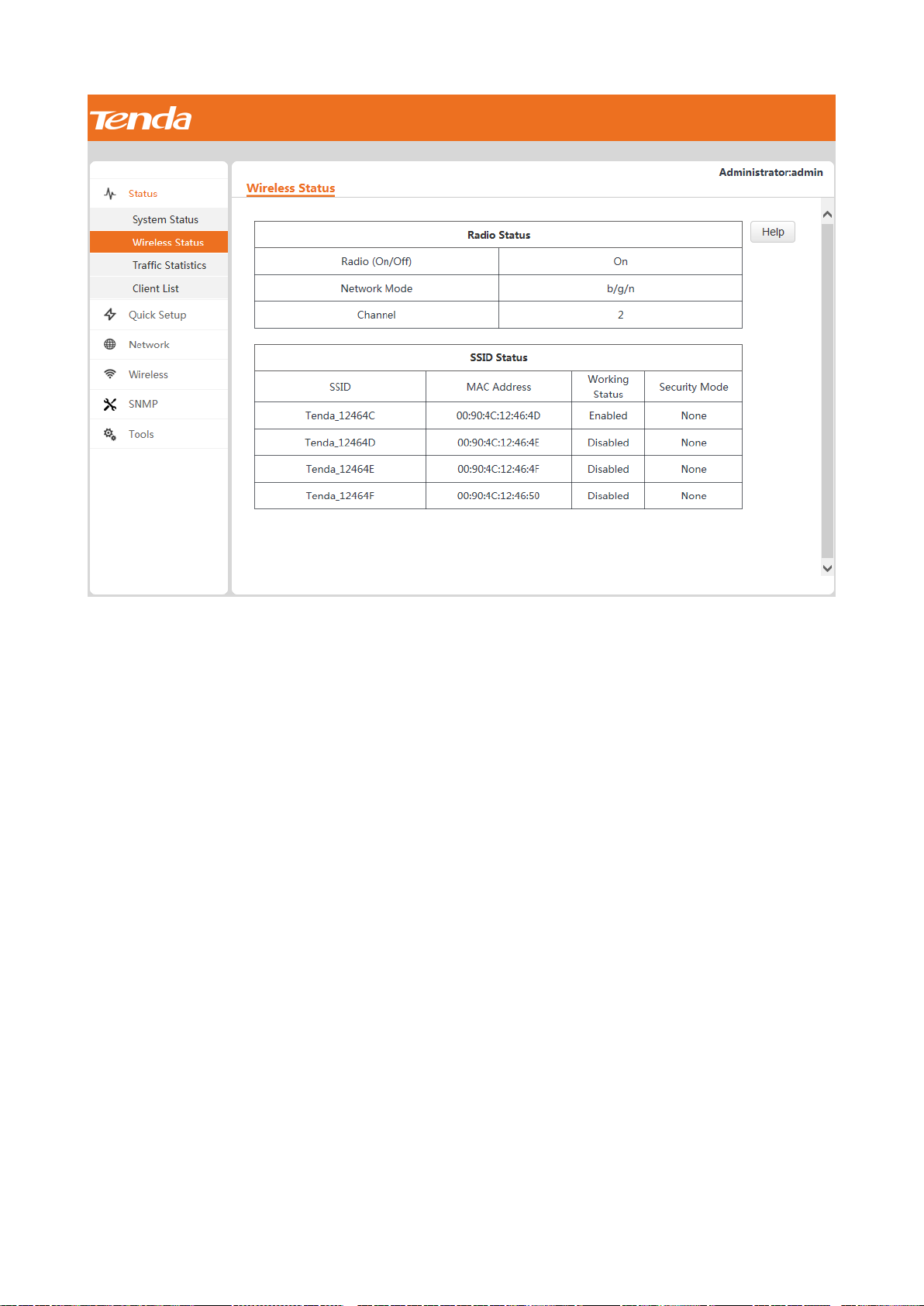
4.1.2 Wireless Status
To view the radio status, SSID status, and WDS status (available when the AP works in WDS mode) of the AP,
choose Status > Wireless Status.
Page 23
4.1.3 Traffic Statistics
To view the total transmitted traffic, total received traffic, total number of transmitted packets, and total number
of received packets corresponding to each SSID of the AP, choose Status > Traffic Statistics.
Page 24
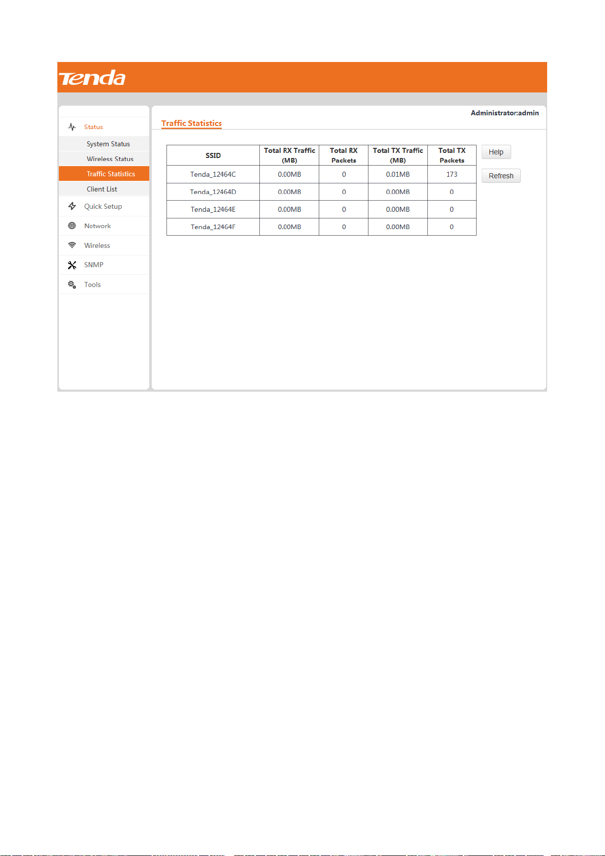
You can click Refresh to view the latest traffic statistics.
4.1.4 Client List
To view the MAC address, IP address, connection uptime, transmit speed, and receive speed of each wireless
client connected to the AP, choose Status > Client List.
Page 25

You can select an SSID from the drop-down list box in the upper-right corner to view information about the
wireless clients connected to the AP using the SSID.
4.2 Quick Setup
Choose Quick Setup. The page displays the parameters that enable you to quickly configure the AP so that
wireless clients can connect to the WiFi network of the AP and access the internet through the AP
The AP can work in AP, WDS, or AP+Client mode. By default, it works in AP mode.
Page 26
4.2.1 AP Mode
In this mode, the AP connects to the internet using an Ethernet cable and converts wired signals into wireless
signals to provide wireless network coverage. The following figure shows the topology.
Procedure:
The Mixed WPA/WPA2-PSK security mode and AES encryption algorithm are used as an example to
describe the configuration procedure. If you need to use another security mode, refer to Section 4.4.1
"Basic Settings."
Step 1 Set Mode to AP Mode.
Step 2 (Optional) Set SSID to a wireless network name.
Step 3 Set Security Mode to Mixed WPA/WPA2-PSK, Cipher Type to AES, and Security Key to the password of
the wireless network.
Step 4 Click Save.
---End
4.2.2 WDS Mode
In this mode, the AP is used to set up a distributed wireless system that features broader wireless network
coverage.
Page 27

Parameter
Description
Mode
It specifies the working mode of the AP. In WDS mode, the AP can be bridged with a
maximum of 4 APs at the same time.
SSID
It specifies the SSID of a peer AP. You can click Enable Scan and select the SSID of the
peer AP from the detected SSIDs.
Security Mode
It specifies the security mode of a peer AP.
When you click Enable Scan and select the SSID of the peer AP from the detected SSIDs,
the local AP automatically obtains related security settings (including Security Mode,
Cipher Type, Authentication Type, and Default Key) of the peer AP except Security Key.
MAC Address
It specifies the MAC address corresponding to the SSID of a peer AP.
When you click Enable Scan and select the SSID of the peer AP from the detected SSIDs,
the local AP automatically sets the corresponding MAC Address parameter to the SSID
of the peer AP.
Remote AP's
channel
It specifies the channel of a peer AP.
When you click Enable Scan and select the SSID of the peer AP from the detected SSIDs,
the local AP automatically obtains related channel settings (including Remote AP's
Network Mode, Remote AP's channel, Remote AP's Channel Bandwidth, and Remote
AP's Extension Channel) of the peer AP.
WDS mode parameter description
Page 28

Enable Scan
It is used to detect information about nearby wireless signals of wireless devices,
including SSIDs, MAC addresses, network modes, signal bandwidth, channels, extension
channels, security modes, and signal strength.
IP Address
SSID
Security Mode
Security Key (Wireless Network
Password)
192.168.0.254
Tenda_1
Mixed WPA/WPA2-PSK
87654321
The WDS function must be configured on all the APs to be bridged in WDS mode. All the APs must share the same
SSID, channel, security mode, and security key.
The APs to be bridged in WDS mode must be assigned different IP addresses belonging to the same network
segment.
Example Application of the WDS Mode
An AP has been installed in a hotel. Nevertheless, the signal of the AP is weak in some rooms because of limited
wireless coverage of the AP and blockage such as walls. As a result, guests in the rooms are unable to properly
access the internet through the AP.
To improve the signal in the other rooms, you can install one AP in each room and use the additional APs to
repeat the wireless signal of the original AP in WDS mode, so as to extend wireless coverage and enable guests in
the rooms to properly access the internet.
1-to-1 WDS bridging
The following figure shows the topology.
Procedure:
Step 1 Log in to the web UI of AP1 and check the basic information about AP1. Assume that AP1 has the basic
information described in the following table.
Step 2 Log in to the web UI of AP2, change its IP address to an IP address that is different from the IP address
of AP1 but belongs to the same network segment of AP1, such as 192.168.0.253. For details, refer to
Section 4.3.1 "LAN Setup."
Step 3 Use the new IP address to log in to the web UI of AP2, and configure AP2 to repeat the wireless signal
of AP1 in WDS mode.
Page 29

1. Choose Quick Setup, set Mode to WDS Mode, and click Enable Scan.
2. Select the SSID of AP1 from the detected SSIDs. In this example, the SSID of AP1 is Tenda_1.
3. Set Security Key to the wireless network password of AP1. In this example, the security key is
87654321.
4. Click Save.
The SSID of AP2 changes to the SSID of AP1 when the configuration is saved.
Page 30

Step 4 Log in to the web UI of AP1 and perform step 3 to configure AP1 to repeat the wireless signal of AP2 in
WDS mode. After configuration is complete, Connected appears to the right of the corresponding MAC
address, indicating that bridging is successful. See the following figure.
Page 31

---End
IP Address
SSID
Security Mode
Security Key (Wireless
Network Password)
192.168.0.254
Tenda_1
Mixed WPA/WPA2-PSK
87654321
1-to-many (maximum: 4) WDS bridging
The following figure shows the topology.
Procedure:
Step 1 Log in to the web UI of AP1 and check the basic information about AP1. Assume that AP1 has the basic
information described in the following table.
The IP addresses of AP2, AP3, AP4, and AP5 must be different from the IP address of AP1 but belong to
the same network segment as the IP address of AP1. For example, you can set them to 192.168.0.2,
192.168.0.3, 192.168.0.4, and 192.168.0.5.
Step 2 Log in to the web UIs of AP2, AP3, AP4, and AP5, change the LAN port IP addresses of the APs, and
configure the APs to repeat the wireless signal of AP1 in WDS mode. For details about the wireless
signal repeating, refer to step 3 in 1-to-1 WDS bridging.
Step 3 Log in to the web UI of AP1 and configure AP1 to repeat the wireless signals of the other APs.
1. Choose Quick Setup, set Mode to WDS Mode, and click Enable Scan.
2. Select the entries of AP2, AP3, AP4, and AP5 on the scan result list. (The SSIDs of the APs on the list are
3. Set Security Key to the wireless network password of AP1, which is 87654321 in this example.
4. Click Save.
the same as the SSID of AP1, which is Tenda_1 in this example.)
Page 32

---End
After configuration is complete, Connected appears to the right of the corresponding MAC addresses, indicating
that bridging is successful. See the following figure.
Page 33

4.2.3 AP+Client Mode
In this mode, you can enable this AP to repeat the wireless signal of a peer AP for broader wireless network
coverage simply by configuring this AP.
Example Application of the AP+Client Mode
An AP has been installed in a restaurant. Nevertheless, the signal of the AP is weak in some rooms because of
limited wireless coverage of the AP and blockage such as walls. As a result, guests in the rooms are unable to
properly access the internet through the AP.
To improve the signal in the rooms, you can install one or more APs and use the additional APs to repeat the
wireless signal of the original AP in AP+Client mode, so as to extend wireless coverage and enable guests in the
rooms to properly access the internet.
Page 34

IP Address
SSID
Security Mode
Security Key (Wireless
Network Password)
192.168.0.254
Tenda_1
Mixed WPA/WPA2-PSK
87654321
The following figure shows the topology.
Procedure:
Step 1 Log in to the web UI of AP1 and check the basic information about AP1. Assume that AP1 has the basic
information described in the following table.
Step 2 Log in to the web UI of AP2, change its IP address to an IP address that is different from the IP address
of AP1 but belongs to the same network segment of AP1, such as 192.168.0.253. For details, refer to
Section 4.3.1 "LAN Setup."
Step 3 Use the new IP address to log in to the web UI of AP2, choose Quick Setup, set Mode to APClient
mode, and click Enable Scan.
Step 4 Select the SSID of AP1 from the detected SSIDs. In this example, the SSID of AP1 is Tenda_1.
Step 5 Set Security Key to the wireless network password of AP1, which is 87654321 in this example.
Step 6 Click Save.
Page 35

---End
After AP2 repeats the wireless signal of AP1, wireless devices such as smart phones can search for and connect to
the wireless signal of AP2, and access the internet through AP2. (In this example, the SSID of AP2 is
Tenda_123456.)
4.3 Network Settings
4.3.1 LAN Setup
To view the MAC address, device name, IP address obtaining mode, and other related information of the LAN
port of the AP, choose Network > LAN Setup.
Page 36

The AP supports the Static IP and Dynamic IP modes for obtaining an IP address for the LAN port.
If you change the IP address of the LAN port, change the IP address of your management computer as
well so that the two IP addresses belong to the same network segment. Then, use the new IP address
of the LAN port to log in to the web UI of the AP.
IP Address Obtaining Mode – Static IP
This mode enables you to set the IP address, subnet mask, gateway IP address, primary DNS server, and
secondary DNS server of the AP. It is applicable to a scenario with only one or a few APs.
Procedure:
Assume that the AP IP address is 192.168.1.254, and the default gateway IP address and DNS server IP
address are 192.168.1.1.
Step 1 Set Address Mode to Static IP.
Step 2 Set IP Address.
Step 3 Set Subnet Mask to the subnet mask of the IP address. Generally the subnet mask is 255.255.255.0.
Step 4 Set Gateway to the IP address of the gateway of the AP.
Step 5 Set Primary DNS Server to the IP address of the primary DNS server of the AP. If another DNS server is
available, set Secondary DNS Server to the IP address of the additional DNS server.
Step 6 Click Save.
---End
IP Address Obtaining Mode – Dynamic IP
This mode enables the AP to automatically obtain an IP address, subnet mask, gateway IP address, primary DNS
server IP address, and secondary DNS server IP address from a DHCP server in the network. If a large number of
Page 37

Parameter
Description
MAC Address
It specifies the MAC address of the LAN port of the AP.
The default primary SSID of the AP is Tenda_XXXXXX, where XXXXXX indicates the
last 6 characters of this MAC address.
Address Mode
It specifies the IP address obtaining mode of the AP. The default option is Static IP.
Static IP: It indicates that the IP address, subnet mask, gateway, and DNS server
information of the AP is set manually.
Dynamic IP: It indicates that the IP address, subnet mask, gateway, and DNS server
information of the AP is obtained from a DHCP server in your LAN.
If Address Mode is set to Dynamic IP, you can log in to the web UI of the AP only
with the IP address assigned to the AP by the DHCP server. The IP address is
specified on the client list of the DHCP server.
IP Address
It specifies the IP address of the AP if Address Mode is set to Static IP. The default IP
address is 192.168.0.254 and you can change it as required.
This IP address also functions as the management IP address of the AP. You can
use this IP address to log in to the web UI of the AP to manage the AP.
Subnet Mask
It specifies the subnet mask of the IP address of the AP if Address Mode is set to
Static IP. The default subnet mask is 255.255.255.0 and you can change it as
required.
Gateway
It specifies the gateway of the AP if Address Mode is set to Static IP. The default
APs are deployed, you can adopt this mode to prevent IP address conflicts and effectively reduce your workload.
Procedure:
Step 1 Set Address Mode to Dynamic IP.
Step 2 Click Save.
---End
Parameter Description
Page 38

Parameter
Description
gateway IP address is 192.168.0.1 and you can change it as required.
Primary DNS Server
It specifies the primary DNS server of the AP if Address Mode is set to Static IP. The
default IP address of the primary DNS server is 192.168.0.1 and you can change it as
required.
Secondary DNS Server
(optional)
It specifies the secondary DNS server of the AP if Address Mode is set to Static IP.
This IP address is optional.
Device Name
It specifies the device name of the AP. The default device name is in the format of
Model+Hardware version number.
You are recommended to change the device name so that you can quickly locate the
AP when managing the AP remotely.
4.3.2 DHCP Server
DHCP Server
The DHCP server function of the AP can automatically assign IP addresses to clients connected to the AP. To
configure the function, choose Network > DHCP Server.
Procedure for enabling and configuring the DHCP server function:
Step 1 Select the Enable check box of DHCP Server.
Step 2 Set Start IP to the start IP address of the IP address pool, which contains the IP addresses that can be
assigned by the DHCP server to clients.
Step 3 Set End IP to the end IP address of the IP address pool.
Step 4 Set Lease Time to the time when an IP address is available to a client. The default option 1 day is
recommended.
Step 5 Set Subnet Mask to the subnet mask of the IP addresses. The default value 255.255.255.0 is
recommended.
Page 39

Parameter
Description
DHCP Server
It specifies whether to enable the DHCP server function. To enable it, select the check
box. To disable it, deselect the check box. By default, it is disabled.
Start IP
It specifies the first IP address that can be assigned by the DHCP server to a client. The
default value is 192.168.0.100.
End IP
It specifies the last IP address that can be assigned by the DHCP server to a client. The
default value is 192.168.0.200.
Lease Time
It specifies the validity period of an IP address assigned by the DHCP server to a client.
The default value is 1 day.
Subnet Mask
It specifies the subnet mask assigned by the DHCP server to clients. The default value
is 255.255.255.0.
Gateway
It specifies the gateway IP address assigned by the DHCP server to clients. The default
value is 192.168.0.254.
When a client accesses a server or host located outside the network segment
where the client resides, the data from and to the client must be forwarded by
the gateway. Generally, the IP address of the gateway is the LAN IP address of the
router in your LAN.
Primary DNS Server
It specifies the primary DNS server IP address assigned by the DHCP server to clients.
The default value is 192.168.0.254.
To enable clients to access web pages using domain names, set this parameter to
a correct DNS server IP address or DNS proxy IP address.
Secondary DNS
Server (optional)
It specifies the secondary DNS server IP address assigned by the DHCP server to
clients. This IP address is optional.
Step 6 Set Gateway to the gateway IP address to be assigned by the DHCP server to clients.
Step 7 Set Primary DNS Server to the IP address of the primary DNS server assigned by the DHCP server to
clients. If another DNS server IP address is available, set Secondary DNS Server to that IP address.
Step 8 Click Save.
---End
If another DHCP server is available in your LAN, ensure that the IP address pool of the AP does not
overlap the IP address pool of that DHCP server. Otherwise, IP address conflicts may occur.
Parameter description
DHCP Client List
To view information about the clients that obtain IP addresses from the DHCP server function of the AP, choose
Network > DHCP Server and click the DHCP Client List tab.
Page 40

You can click Refresh to view the latest client information.
4.4 Wireless Settings
4.4.1 Basic Settings
To view basic wireless settings of the AP, choose Wireless > Basic.
Procedure:
If there is no special requirement regarding the parameters not described in this procedure, retain the
default settings.
Page 41

Parameter
Description
SSID
It specifies the SSID to be configured.
The AP allows 4 SSIDs. The default SSID is the primary SSID of the AP, which is
Tenda_XXXXXX, where XXXXXX indicates the last 6 characters in the MAC address
specified on the label on the external surface of the AP.
Enable
It specifies whether to enable the selected SSID.
By default, the primary SSID is enabled and the other SSIDs are disabled. You can
enable them as required.
Broadcast SSID
It specifies whether to broadcast the selected SSID.
Enable: It indicates that the AP broadcasts the SSID and the SSID can be detected by
clients.
Disable: It indicates that the AP does not broadcast the SSID and the SSID cannot be
detected by clients. If a user wants to connect to the wireless network corresponding
to this SSID, the user must enter the SSID manually.
This AP can automatically hide its SSID. When the number of clients connected to
the AP with an SSID of the AP reaches the upper limit, the AP stops broadcasting
the SSID.
AP isolation
It specifies whether to isolate the wireless clients connected to the AP with the
selected SSID.
Enable: It indicates that the wireless clients connected to the AP with the selected
SSID cannot communicate with each other. This improves wireless network security.
Disable: It indicates that the wireless clients connected to the AP with the selected
SSID can communicate with each other.
WMF
It specifies whether to forward multicast packets through unicast tunnels. Generally,
multicast packets are usually transmitted at the lowest rate, such as 1 Mbps, leading to
poor transmission efficiency. WMF leverages the high auto-negotiated rate, reliable
feedback mechanism, and other advantages of unicast packets to address multicast
problems such as video playback stalls caused by packet loss and long delays over a
Step 1 Select the SSID to be configured from the SSID drop-down list box.
Step 2 Select the Enable check box to enable the selected SSID.
Step 3 Set Client limit to the maximum number of wireless clients that can be connected to the AP using the
selected SSID.
Step 4 Change the value of the SSID text box to a required wireless network name.
Step 5 (Skip this step if your SSID does not include Chinese characters.) Set Chinese SSID Encode to an
encoding format of the Chinese characters in your SSID.
Step 6 Select a security mode from the Security Mode drop-down list box for your SSID. For the detailed
security mode configuration procedure, refer to Security Mode.
Step 7 Click Save.
---End
Parameter description
Page 42

Parameter
Description
wireless network.
Client limit
It specifies the maximum number of wireless clients that can connect to the AP with
the selected SSID.
After this upper limit is reached, the AP rejects new connection requests from clients.
SSID
It enables you to change the selected SSID. Chinese characters are allowed in an SSID.
Chinese SSID
Encode
It specifies the encoding format of Chinese characters in an SSID. The default value is
UTF8.
If 2 or more SSIDs of the AP are enabled, you are recommended to set this parameter
to UTF-8 for some SSIDs and to GB2312 for the other SSIDs, so that any wireless client
can identify one or both SSIDs that contain Chinese characters.
Security Mode
It specifies the encryption type of the selected SSID. None indicates that any wireless
client can connect to the AP using the selected SSID. This option is not recommended
because it affects network security.
The AP supports the WEP, WPA-PSK, WPA2-PSK, Mixed WPA/WPA2-PSK, WPA, and
WPA2 security modes, which are elaborated in the following section.
WEP
Wired Equivalent Privacy (WEP) uses a static key to encrypt all exchanged data, and ensures that a wireless LAN
has the same level of security as a wired LAN. If this encryption algorithm is used, the AP can reach a maximum
wireless transmission rate of 54 Mbps.
WEP supports the Open, Shared, and 802.1x encryption types.
Many smart phones can use only WEP key 1 to connect to a WEP-encrypted wireless network with the
encryption type being Open or Shared. Therefore, if Security Mode is set to WEP and Encryption Type
is set to Open or Shared, set Default Key to the value of WEP Key 1.
Procedure for configuring the basic wireless settings with the authentication type being Open or Shared:
Page 43

Assume that WEP key 1 is the default WEP key and the key is set to 54321 and ASCII.
Step 1 Select the SSID to be configured from the SSID drop-down list box, such as Tenda_123456.
Step 2 Set Security Mode to WEP.
Step 3 Set Encryption Type to Open or Shared.
Step 4 Set Default Key to Security Key 1.
Step 5 Set WEP Key 1 to 54321 and ASCII.
Step 6 Click Save.
----End
Procedure for configuring the basic wireless settings with the authentication type being 802.1x:
Assume that the IP address, port number, and password of the RADIUS server are 192.168.0.88, 1812,
and 12345678 respectively.
Step 1 Select the SSID to be configured from the SSID drop-down list box, such as Tenda_123456.
Step 2 Set Security Mode to WEP.
Step 3 Set Encryption Type to 802.1x.
Step 4 Set RADIUS Server to the IP address 192.168.0.88 of the RADIUS server.
Step 5 Set RADIUS Port to the authentication port number 1812 of the RADIUS server.
Page 44

Parameter
Description
Encryption Type
It specifies the encryption type for the WEP security mode of the AP. The options
include Open, Shared, and 802.1x.
The options share the same encryption process.
Open
It specifies that authentication is not required if the WEP security mode is used.
In this case, a wireless client can connect to the AP without being authenticated, and
the data exchanged between them is encrypted in WEP security mode.
Shared
It specifies that a shared key is used for authentication if the WEP security mode is
used.
In this case, a wireless client must use a preset WEP key to connect to the AP. The
wireless client can be connected to the AP only if the WEP key is the same as that of
the AP.
802.1x
It specifies that 802.1x authentication is required if the WEP security mode is used.
In this case, ports are enabled when authenticated clients connect to the AP, and
disabled when non-authenticated users connect to the AP.
Default Key
It specifies the default WEP key for the Open and Shared encryption types.
For example, if the default key is set to WEP key 2, a wireless client can connect to the
Step 6 Set RADIUS Password to the password 12345678 of the RADIUS server.
Step 7 Click Save.
---End
WEP parameter description
Page 45

Parameter
Description
AP only with WEP key 2.
ASCII
It allows 5 or 13 ASCII characters in a WEP key.
Hex
It allows 10 or 26 hexadecimal characters in a WEP key.
RADIUS Server
It specifies the IP address of the RADIUS server for authentication.
RADIUS Port
It specifies the port number of the RADIUS server for authentication.
RADIUS Password
It specifies the password of the RADIUS server for authentication.
WPA-PSK, WPA2-PSK, and Mixed WPA/WPA2-PSK
WPA-PSK is formulated based on IEEE 802.11i draft 3, whereas WPA2-PSK is formulated based on the final IEEE
802.11i release. Therefore, WPA2-PSK features higher security than WPA-PSK.
Both WPA-PSK and WPA2-PSK adopt a preshared key for authentication, while the AP generates another key for
data encryption. This prevents the vulnerability caused by static WEP keys, and makes WPA-PSK and WPA2-PSK
suitable for ensuring security of home wireless networks. Nevertheless, because the initial preshared key for
authentication is manually set and all clients use the same key to connect to the same AP, the key may be
disclosed unexpectedly. This makes WPA-PSK and WPA2-PSK not suitable for scenarios where high security is
required.
Procedure for configuring the WPA-PSK, WPA2-PSK, or Mixed WPA/WPA2-PSK security mode:
Assume that Cipher Type and Key are AES and 87654321 respectively.
Step 1 Select the SSID to be configured from the SSID drop-down list box, such as Tenda_123456.
Step 2 Set Security Mode to Mixed WPA/WPA2-PSK, WPA-PSK, or WPA2-PSK.
Step 3 Set Cipher Type to AES.
Step 4 Set Key to 87654321.
Step 5 Click Save.
Page 46

Parameter
Description
Security Mode
It specifies the encryption type of the selected SSID. Select WPA-PSK, WPA2-PSK, or
Mixed WPA/WPA2-PSK.
WPA-PSK
This encryption type supports the AES and TKIP encryption algorithms.
WPA2-PSK
This encryption type supports the AES, TKIP, and TKIP&AES encryption algorithms.
Mixed
WPA/WPA2-PSK
It indicates that the AP works in the Mixed WPA/WPA2-PSK security mode, and
wireless clients adopting the WPA-PSK or WPA2-PSK security mode can connect to
the AP.
Cipher Type
It specifies the encryption algorithm corresponding to the selected security mode. If
Security Mode is set to WPA-PSK, this parameter has the AES and TKIP values. If
Security Mode is set to WPA2-PSK or Mixed WPA/WPA2-PSK, this parameter has the
AES, TKIP, and TKIP&AES values.
AES
It is short for Advanced Encryption Standard. If this encryption algorithm is used, the
AP can reach a maximum wireless transmission rate of 300 Mbps.
TKIP
It is short for Temporal Key Integrity Protocol. If this encryption algorithm is used, the
AP can reach a maximum wireless transmission rate of 54 Mbps.
TKIP&AES
It indicates that both TKIP and AES encryption algorithms are supported. Wireless
clients can connect to the AP based on TKIP or AES.
Key
It specifies a preshared WPA key. A WPA key can contain 8 to 63 ASCII characters or 8
to 64 hexadecimal characters.
---End
Parameter description
Page 47

Parameter
Description
Key Update Interval
It specifies the automatic update interval of the key for data encryption. A shorter
interval results in higher data security.
WPA and WPA2
To address the key management weakness of WPA-PSK and WPA2-PSK, the WiFi Alliance puts forward WPA and
WPA2, which use 802.1x to authenticate clients and generate data encryption–oriented root keys. WPA and
WPA2 use the root keys to replace the preshared keys that set manually, but adopt the same encryption process
as WPA-PSK and WPA2-PSK.
WPA and WPA2 uses 802.1x to authenticate clients and the login information of a client is managed by the client.
This effectively reduces the probability of information leakage. In addition, each time a client connects to the AP
that adopts the WPA or WPA2 security mode, the RADIUS server generates a data encryption key and assigns it
to the client. This makes it difficult for attackers to obtain the key. These features of WPA and WPA2 help
significantly increase network security, making WPA and WPA2 the preferred security modes of wireless
networks that require high security.
Procedure for configuring the WPA or WPA2 security mode:
Assume that the IP address, port number, and password of the RADIUS server are 192.168.0.88, 1812,
and 12345678 respectively, and the encryption algorithm is AES.
Step 1 Select the SSID to be configured from the SSID drop-down list box, such as Tenda_123456.
Step 2 Set Security Mode to WPA or WPA2.
Step 3 Set RADIUS Server to the IP address 192.168.0.88 of the RADIUS server.
Step 4 Set RADIUS Port to the authentication port number 1812 of the RADIUS server.
Step 5 Set RADIUS Password to the password 12345678 of the RADIUS server.
Step 6 Set Cipher Type to AES.
Step 7 Click Save.
Page 48

Parameter
Description
Security Mode
It specifies the security mode of the selected SSID. Select WPA or WPA2.
WPA
This encryption type supports the AES and TKIP encryption algorithms.
WPA2
This encryption type supports the AES, TKIP, and TKIP&AES encryption algorithms.
RADIUS Server
It specifies the IP address of the RADIUS server for authentication.
RADIUS Port
It specifies the port number of the RADIUS server for authentication.
RADIUS Password
It specifies the password of the RADIUS server for authentication.
Cipher Type
It specifies the encryption algorithm corresponding to the selected security mode. The
available options include AES, TKIP, and TKIP&AES.
AES
It is short for Advanced Encryption Standard. If this encryption algorithm is used, the AP
can reach a maximum wireless transmission rate of 300 Mbps.
TKIP
It is short for Temporal Key Integrity Protocol. If this encryption algorithm is used, the AP
can reach a maximum wireless transmission rate of 54 Mbps.
TKIP&AES
It indicates that both TKIP and AES encryption algorithms are supported. Wireless clients
can connect to the AP based on TKIP or AES.
---End
Parameter description
Page 49

Parameter
Description
Key Update
Interval
It specifies the automatic update interval of a WPA key for data encryption. A shorter
interval results in higher data security.
Parameter
Description
Enable Wireless
It specifies whether to enable the wireless function of the AP.
Country
It specifies the country or region where the AP is used. Different countries or regions
have different channel regulations.
Network Mode
It specifies the 802.11 network mode of the AP. By default, the AP works in 11b/g/n
mixed mode.
11b: It indicates that only clients working in the 11b network mode can connect to the
AP. In this network mode, the AP can reach a maximum wireless transmission rate of
11 Mbps.
11g: It indicates that only clients working in the 11g network mode can connect to the
AP. In this network mode, the AP can reach a maximum wireless transmission rate of
54 Mbps.
11b/g mixed: It indicates that only clients working in the 11b or 11g network mode
can connect to the AP. In this network mode, the AP can reach a maximum wireless
4.4.2 Radio Settings
To view the radio parameters of the AP, choose Wireless > Radio. If the AP works in AP+Client or WDS mode, the
radio parameters cannot be changed.
Parameter description
Page 50

Parameter
Description
transmission rate of 54 Mbps.
11b/g/n mixed: It indicates that only clients working in the 11b, 11g, or 11n network
mode can connect to the AP. In this network mode, the AP can reach a maximum
wireless transmission rate of 300 Mbps.
Channel
It specifies the operating channel of the AP.
Channel
Bandwidth
It specifies the bandwidth of the operating channel of the AP. This parameter is effective
only for the 802.11b/g/n mixed network mode. The 20/40 option offers a maximum
wireless transmission rate almost twice of that offered by the 20 option.
Expansion Channel
It specifies an additional channel used to increase the channel bandwidth if the AP works
in the 802.11b/g/n mixed network mode and the channel bandwidth option 20/40 is
selected.
Channel Lockout
It is used to lock the selected channel. After a channel is locked, parameters of the
channel cannot be changed, including Country, Network Mode, Channel, Channel
Bandwidth, and Expansion Channel.
SSID Isolation
It specifies whether to isolate the wireless clients connected to the AP with different
SSIDs.
Disable: It indicates that the wireless clients connected to the AP with different SSIDs
can communicate with each other.
Enable: It indicates that the wireless clients connected to the AP with different SSID
cannot communicate with each other. This improves wireless network security.
WMM Capable
It is short for Wi-Fi Multimedia, which helps improve multimedia data (such as data of
online videos) transmission performance of wireless networks. It is recommended that
you enable this function.
APSD Capable
It is short for Automatic Power Save Delivery, and is effective only if the WMM function
is enabled. It is recommended that you disable this function.
4.4.3 Channel Scan
This function is used to detect nearby wireless networks of the AP, as well as the MAC addresses, network modes,
channels, channel bandwidths, security modes, and signal strengths of the wireless networks. To use the function,
choose Wireless > Site Survey.
Page 51

By default, the channel scan function of the AP is disabled. You can click Enable Scan and wait a moment for the
scan result. See the following figure.
According to the scan result, you can select the least-used channel as the operating channel of the AP for better
wireless transmission efficiency.
Page 52

Parameter
Description
Beacon Interval
It specifies the interval for transmitting the Beacon frame. The value range is 20 to 999. The
unit is millisecond.
The Beacon frame is transmitted at the specified interval to announce the presence of a
wireless network. Generally, a smaller interval enables wireless clients to connect to the AP
more quickly, while a larger interval ensures higher data transmission efficiency.
Fragment
Threshold
It specifies the threshold of a fragment. The value range is 256 to 2346. The unit is byte.
Fragmenting is a process that divides a frame into several fragments, which are transmitted
and acknowledged separately. If the size of a frame exceeds this threshold, the frame is
fragmented.
In case of a high error rate, you can reduce the threshold to enable the AP to resend only
the fragments that have not been sent successfully, so as to increase the frame
throughput.
In an environment without interference, you can increase the threshold to reduce the
number of acknowledgement times, so as to increase the frame throughput.
4.4.4 Advanced Settings
To view the advanced parameters for configuring the wireless performance of the AP, choose Wireless >
Advanced.
It is recommended that you change the settings only under the instruction of professional personnel,
so as to prevent decreasing the wireless performance of the AP.
Parameter description
Page 53

Parameter
Description
RTS Threshold
It specifies the frame length threshold for triggering the RTS/CTS mechanism.
If a frame exceeds this threshold, the RTS/CTS mechanism is triggered to reduce conflicts.
The value range is 1 to 2347. The unit is byte.
Set the RTS threshold based on the actual situation. An excessively small value increases the
RTS frame transmission frequency and bandwidth requirement. A higher RTS frame
transmission frequency enables a wireless network to recover from conflicts quicker. For a
wireless network with high user density, you can reduce this threshold for reducing
conflicts.
The RTS mechanism requires some network bandwidth. Therefore, it is triggered only when
frames exceed this threshold.
DTIM Interval
It is short for Delivery Traffic Indication Message, and specifies the countdown before the
AP transmits broadcast and multicast frames in its cache. The value range is 1 to 255. The
unit is Beacon interval.
For example, if DTIM Interval is set to 1, the AP transmits all cached frames at the Beacon
interval.
Receive Signal
Strength
It specifies the minimum strength of received signals acceptable to the AP.
If the strength of the signals transmitted by a wireless device is weaker than this threshold,
the wireless device cannot connect to the AP. An appropriate value of this parameter
ensures that wireless clients connect to APs with strong signals.
Output Power
It specifies the transmit power of the AP. The unit is dBm. The value range is 8 dBm to 23
dBm.
A greater transmit power of the AP offers broader network coverage. You can slightly
reduce the transmit power to improve the wireless network performance and security.
Power Lockout
It specifies whether the current transmit power settings of the AP can be changed.
Preamble
It specifies the time when data is transmitted between a wireless client and the AP. The
time is notified to other wireless clients to prevent conflicts. During transmission, the
preamble as well as the synchronization signal and frame interval is transmitted before
working data.
In data frames for wireless transmission, a long preamble results in short working data.
Therefore, a short preamble can be used to improve wireless transmission efficiency.
It is optional for 802.11b devices to support short preambles. It is mandatory for 802.11g
devices to support short preambles.
Signal
Transmission
It specifies the signal transmission mode for a specific scenario.
Coverage-oriented: This mode enables the AP to provide broader coverage when the AP
is deployed in an area with low AP density, such as an office, a warehouse, or a hospital.
Capacity-oriented: This mode reduces inter-AP interference when the AP is deployed in
an area with high AP density, such as a venue, an exhibition hall, a banquet hall, a
stadium, a college classroom, or a departure lounge.
Signal
Reception
It specifies the signal reception mode for a specific scenario.
Coverage-oriented: This mode enables more wireless devices to connect to the AP in an
Page 54

Parameter
Description
area with low AP density.
Capacity-oriented: This mode ensures that each wireless device in an area with high AP
density connects to the AP with the strongest signal.
Default: This mode enables the AP to achieve a balance between the other two modes.
Parameter
Description
SSID
It specifies the SSID that requires wireless client access control.
MAC Filter Mode
It specifies the mode for filtering MAC addresses.
Disable: It indicates that access control is disabled.
Allow: It indicates that only the wireless clients on the access control list can
connect to the AP with the selected SSID.
Deny: It indicates that only the wireless clients on the access control list cannot
connect to the AP with the selected SSID.
4.4.5 Access Control
To control access of wireless clients to the AP by MAC address, choose Wireless > Access Control.
Parameter description
This page also displays a list of wireless clients that have connected to the AP with the selected SSID. You can
select wireless clients from the list to implemented access control.
Page 55

Wireless client list
Example Application of Wireless Control
Networking requirement
The laptops whose MAC addresses are C8:3A:35:12:12:12 and C8:3A:35:14:14:14 are not allowed to
connect to the AP with the SSID Tenda_123456.
Procedure
Step 1 Set SSID to Tenda_123456 and MAC Filter Mode to Deny.
Step 2 Enter C8:3A:35:12:12:12 in the MAC Address text box and click Add.
Step 3 Change the value of the MAC Address text box to C8:3A:35:14:14:14 and click Add.
Page 56

Access control list
Step 4 Click Save.
4.4.6 QVLAN Settings
This AP supports IEEE 802.1Q VLANs. After the QVLAN function is enabled, the AP can work with a switch that
supports the QVLAN function to set up multiple wireless VLANs. Wireless clients connected to different VLANs
cannot communicate with each other.
To configure the function, choose Wireless > QVLAN.
---End
Page 57

Parameter
Description
Enable
It specifies whether to enable the QVLAN function. By default, it is disabled.
PVID
It specifies the ID of the default native VLAN of the trunk port. The default ID is 1.
Manage VLAN
It specifies the ID of the AP management VLAN. The default ID is 1.
After changing the management VLAN, you can manage the AP only after connecting
your computer to the new management VLAN.
SSID
It specifies the wireless network names of the AP.
VLAN ID
It specifies VLAN IDs corresponding to SSIDs. The default VLAN ID is 1000. The VLAN
ID range is 1 to 4094.
Parameter description
Example Application of QVLAN Configuration
Requirement
A hotel needs to enable its guests to access the internet by both wired and wireless means in the
lounge and rooms, its employees to access its LAN server, and its senior managers to access both the
internet and LAN server.
Solution
Define 802.1Q VLANs on its core switch to isolate the three groups of users.
− Deploy i12 and configure multiple SSIDs and the QVLAN function to enable the AP to interwork
with the VLANs defined on the core switch.
− Separately implement wireless network encryption for each SSID and assign different SSIDs to
different groups of users.
Page 58

− There are three groups of users and the AP has four SSIDs. The SSID not assigned to the users can
Port Connected To
VLAN
Link Type
PVID
Guests
2
Access
2
Employees
3
Access
3
Senior managers
4
Access
4
AP
1,2,3,4
Trunk (Traffic of all the VLANs can
pass through the port.)
1
LAN server
3,4
Trunk (Only traffic of VLAN3 and
1
be handled using either of the following methods:
Assign the SSID to the largest group of users, such as the group of guests. This SSID must
Disable the SSID.
Network topology
See the following figure.
adopt the same security mode and VLAN ID as the SSID originally assigned to the group. The
SSIDs must be different. (This method is used as an example for description in this
document.)
Configuration description
VLANs defined on the core switch
Page 59

Port Connected To
VLAN
Link Type
PVID
VLAN4 can pass through the port.)
Gateway with internet
connectivity
2,4
Trunk (Only traffic of VLAN3 and
VLAN4 can pass through the port.)
1
User Group
SSID
VLAN ID
Guests
Hotel1
VLAN2
Employees
Office
VLAN3
Senior managers
Management
VLAN4
Guests
Hotel2
VLAN2
SSIDs and VLANs defined on the AP
AP configuration
Step 1 Log in to the web UI of the AP and choose Wireless > Basic.
Step 2 Enable the 4 SSIDs, change the SSIDs to Hotel1, Office, Management, and Hotel2, configure security
modes for the SSIDs, and save the change.
Step 3 Choose Wireless > QVLAN, enable the QVLAN function, change the VLAN IDs of the SSIDs, and click
Save.
---End
Page 60

Parameter
Description
SNMP
It specifies whether to enable the SNMP agent function of the AP. By default, it is
disabled.
Administrator
Name
It specifies the name of the administrator of the AP. The default name is Administrator.
Device Name
It specifies the device name of the AP. The default device name is in the format of
Model+Hardware version number. For example, the device name of i12 is i12V1.0.
Location
It specifies the location where the AP is used.
Read Community
It specifies the read password shared between the SNMP manager and SNMP agent. The
4.5 SNMP
This AP supports the SNMP agent function. Therefore, you can use SNMP management software to manage the
AP. To configure the function, choose SNMP.
By default, the SNMP agent function is disabled. To enable it, set SNMP to Enable.
Parameter description
Page 61

default password is public.
The SNMP agent function of the AP allows an SNMP manager to use the password to
read variables in the MIB of the AP.
Read/Write
Community
It specifies the read/write password shared between the SNMP manager and SNMP
agent. The default password is private.
The SNMP agent function of the AP allows an SNMP manager to use the password to
read/write variables in the MIB of the AP.
4.6 Tools
4.6.1 Firmware Upgrade
You can download a later firmware version for the AP from http://www.tendacn.com to upgrade the firmware of
the AP for more functions and higher stability. To upgrade the firmware, choose Tools.
Do not power off the AP during an upgrade. Otherwise, the AP may be damaged. If a power failure
occurs during an upgrade, perform the upgrade again. If you cannot access the web UI of the AP after
the power failure, contact the aftersales service for a repair.
Procedure:
Step 1 Download the package of a later firmware version for the AP from http://www.tendacn.com to your
local computer, and decompress the package.
Page 62

Step 2 Log in to the web UI of the AP and choose Tools.
Step 3 Click Browse and choose the AP upgrade file.
Step 4 Click Upgrade.
---End
Wait until the upgrade and reboot process is complete. Choose Tools and check whether the upgrade is
successful based on Current Firmware Version.
4.6.2 Date & Time
The AP provides the system time and login timeout modules for time management.
The time information of the AP is lost when the AP is powered off. If the function for synchronizing the
system time through the internet is enabled, the AP synchronizes the system time after being
reconnected to the internet. Logs can be recorded correctly and the reboot schedule can be executed
correctly only when the system time is correct.
System Time
To configure the system time of the AP so that logs can be recorded correctly and the reboot schedule can be
executed correctly, choose Tools > Time & Date.
You can choose whether to synchronize the system time through the internet or manually set the system time.
By default, the AP synchronizes the system time through the internet.
Synchronizing the system time with internet time servers
Page 63

The AP synchronizes the system time at a specified interval with the time server over the internet.
The AP can perform synchronization only after being connected to the internet. To connect the AP to
the internet, choose Network > LAN Setup and set the IP address, subnet mask, gateway, and DNS
server of the AP.
Procedure:
Step 1 Select Sync with Internet time servers.
Step 2 Set Sync Interval to the synchronization interval. 30 minutes is recommended.
Step 3 Set Time Zone to your time zone.
Step 4 Click Save.
---End
Manually setting the system time
You can manually set the system time of the AP.
Procedure:
Step 1 Deselect Sync with Internet time servers.
Step 2 Enter a correct date and time, or click Sync with Your PC to synchronize the system time of the AP with
the system time (ensure that it is correct) of the computer being used to manage the AP.
Step 3 Click Save.
Page 64

---End
Page Timeout
If a user logs in to the web UI of the AP and performs no operation within the login timeout interval, the AP logs
the user out. To set the interval, choose Tools > Time & Date > Page Timeout.
The default interval is 5 minutes. You can change it as required within the range from 1 minute through 60
Page 65

minutes.
4.6.3 Logs
View Logs
To view the logs of events that occur after the startup of the AP, choose Tools > Logs.
You are recommended to choose Tools > Time & Date and verify the system time of the AP to ensure that the
times of logs are correct. This facilitates real-time network condition monitoring and network fault diagnosis.
To view the latest logs of the AP, click Refresh. To clear the logs on the page, click Clear.
When the AP reboots, the previous logs are lost.
The AP reboots when the AP is powered on after a power failure, the QVLAN function is configured, the firmware is
upgraded, an AP configuration is backed up or restored, or the factory settings are restored.
Log Server
To set the number of logs and log servers, choose Tools > Logs.
Page 66

Number of logs
You can set the maximum number of logs that can be displayed on the page. The value range is from
100 to 300. By default, a maximum of 150 logs can be displayed.
Log server settings
After a log server is specified, the AP sends its logs to the log server. You can view all the historical logs
of the AP on the log server.
Procedure for adding a log server:
Step 1 Click Add.
Page 67

Step 2 Set Log Server IP to the IP address of a log server (192.168.0.88 in this example) over the network.
Step 3 Set Log Server Port to the UDP port number used to send and receive system logs. The default port
number 514 is recommended.
Step 4 Select Enable to enable the log server function.
Step 5 Click Save.
Step 6 Select Enable (To use the following rules, you must check this box.) and click Save.
Page 68

---End
To change the settings of a log server, click Edit corresponding to the log server. To delete the settings of a log
server, click Delete corresponding to the log server.
To ensure that system logs can be sent to a log server, choose Network > LAN Setup and set the IP
address, subnet mask, and gateway of the AP for communicating with the log server.
4.6.4 Configuration Management
Backup & Restore
To access the page for backing up or restoring a configuration, choose Tools > Configuration.
Page 69

Backing up the current configuration
After the AP enters the optimum condition after you greatly change the configuration of the AP, you
are recommended to back up the new configuration.
To back up the configuration, click Backup and follow the on-screen instructions to perform operations.
Restoring a configuration
By restoring an earlier configuration that has been backed up, you can apply the same configuration to
multiple APs or recover an AP after the configuration of the AP is changed unexpectedly.
To restore a configuration, click Browse, select the backup file of the configuration, click Restore, and
follow the on-screen instructions to perform operations.
Restore to Factory Default
If you cannot locate the cause for a failure to access the internet, you can restore the factory settings of the AP to
address the problem. To restore the factory, choose Tools > Configuration > Restore to Factory Default and click
Restore to Factory Default.
Page 70

Reset button
You can also use the reset button on the AP to restore the factory settings. If you forget your login information,
such as the IP address, user name, or password for the AP, you are recommended to use the reset button to
restore the factory settings.
Procedure:
Step 1 After the AP is powered on, hold down the reset button for 8 seconds.
Step 2 Wait about 45 seconds.
---End
After the factory settings are restored, the IP address of the web UI of the AP changes to 192.168.0.254
and the login user name and password change to admin. For other default settings, refer to Appendix C
Default Parameter Settings.
Page 71

4.6.5 Accounts
You are recommended to change the default user name and password of the Administrator account to prevent
unauthorized users from logging in to the web UI of the AP as the administrator and changing the AP
configuration. To manage accounts, choose Tools > Administrator.
The AP allows an administrator account and a user account. The administrator account is assigned all AP
management permissions. The user account is allowed only to view AP settings.
By default, the AP has one administrator account and one user account. Both the user name and password of the
administrator account are admin. Both the user name and password of the user account are user.
To change the user name and password of an account, click Change corresponding to the account. For example,
you can click Change corresponding to the administrator account.
Page 72

1
2
Change the user name and password as required and click Save. The AP displays the login page. Use the new
user name and password to log in.
To delete the user account, click Delete corresponding to the account, and click Save.
Page 73

To add the user account after deleting it, click Change corresponding to the account.
4.6.6 Diagnostics
If a network connection fails, you can use the Ping tool included with the AP to locate the faulty node. To use the
tool, choose Tools > Diagnostics.
4.6.7 Reboot
Reboot
To manually reboot the AP, choose Tools > Reboot, and click Reboot.
When the AP reboots, all wireless connections are released. You are recommended to reboot the AP at
an idle hour.
Page 74

Time Reboot
You can specify an AP reboot schedule to enable the AP to reboot at an idle hour to ensure AP performance. To
specify a reboot schedule, choose Tools > Reboot and click the Time Reboot tab.
Page 75

The AP can reboot at an interval or at a specified time. Choose either as required.
Rebooting the AP at an interval
Configuration procedure:
Step 1 Select the Enable check box.
Step 2 Set Reboot Type to Interval.
Step 3 Set Reboot Interval to 1440.
Step 4 Click Save.
---End
Rebooting the AP at specified time
Procedure:
Step 1 Select the Enable check box.
Step 2 Set Reboot Type to Schedule.
Step 3 Select the day or days when the AP reboots.
Step 4 Set the time when the AP reboots, such as 23:59.
Step 5 Click Save.
Page 76

---End
4.6.8 LED Control
To turn on or off the LED indicator, choose Tools > LED.
When you click Disable all LEDs, the LED indicator of the AP turns off.
Page 77

Appendixes
A. FAQ
Q1. I cannot access the web UI of the AP after entering 192.168.0.254. What should I do?
A1. Check the following items:
Verify that the IP address of your computer is 192.168.0.X (X: 2~253).
Clear the cache of your web browser or replace the web browser, and try login again.
Disable the firewall of your computer or replace the computer, and try login again.
If two or more APs are connected to your network without an AP controller, connect one of the APs to
your network and change the IP address of the AP. Repeat this procedure to change the IP addresses of
the other APs.
The AP may be being managed by an AP controller and therefore its IP address is no longer
192.168.0.254. In that case, log in to the web UI of the AP controller to view the new IP address of the
AP, and log in to the AP using the new IP address.
If you have manually changed the IP address of the AP, change the IP address of your computer to
another IP address that belongs to the same network segment as the new IP address of the AP and log
in again using the new IP address of the AP.
If the problem persists, restore the factory settings of the AP and try login again.
Q2. My wireless AP controller cannot find the AP. What should I do?
A2. Check the following items:
Verify that the devices are connected properly and the AP has started.
If VLANs have been defined on your network, verify that the corresponding VLAN has been added to
your AP controller.
Restart the AP or restore the factory settings of the AP, and try scanning the AP again.
Q3. Can I log in to the web UI of the AP to configure the AP after using an AC to manage the AP?
A3. Yes. You are recommended to change the user name and password of the administrator account (see Section
4.6.5 "Accounts.") if you use an AC to manage the AP. This improves network security.
For more technical assistance, visit our website at http://www.tendacn.com or send your question to
support@tenda.cn. We will help you resolve your problem as soon as possible.
B. Setting the IP Address of Your Computer (Example: Windows 7)
Step 1 Choose Start > Control Panel, click Network and Internet, click Network and Sharing Center, and click
Change adapter settings.
Step 2 Right-click Local Area Connection and choose Properties. Select Internet Protocol Version 4 (TCP/IPv4)
and click Properties.
Page 78

Step 3 Select Use the following IP address. Set IP address to an IP address that is different from the IP
address of the LAN port of the AP but belongs to the same network segment as the IP address of the
LAN port of the AP. Set Subnet mask to 255.255.255.0. Click OK.
Page 79

Parameter
Default Value
Login
IP
192.168.0.254
User Name/Password
Administrator
admin/admin
User
user/user
LAN Setup
Address Mode
Static IP
IP Address (management IP address)
192.168.0.254
Subnet Mask
255.255.255.0
Gateway
192.168.0.1
Primary DNS Server
192.168.0.1
Secondary DNS Server
None
The Local Area Connection Properties dialog box appears.
Step 4 Click OK.
---End
C. Default Parameter Settings
The following table lists the factory settings of the AP.
Page 80

Parameter
Default Value
Device Name
Model+Hardware version number,
such as i12V1.0
DHCP Server
Disable
SNMP
SNMP Agent
Disable
SNMP Parameters
Administrator Name
Administrator
Device Name
Model+Hardware version number,
such as i12V1.0
Location
ShenZhen
Read Community
public
Read/Write Community
private
Tools
System Time
Sync with Internet Time
Servers
Enable
Time Zone
(GMT+08:00) Beijing, Chongqing,
Hong Kong, Urumqi, Taipei
Page Timeout
5 minutes
Number of Logs
150
Time Reboot
Disable
LED Control
Switch on LEDs
Wireless
Settings
Radio Settings
Enable Wireless
Enable
Country
China
Network Mode
11/b/g/n mixed
Channel
Auto
Channel Bandwidth
20/40
Expansion Channel
Auto
Channel Lockout
Enable
SSID Isolation
Disable
WMM Capable
Enable
APSD Capable
Disable
Page 81

Parameter
Default Value
Basic Settings
SSID
Primary SSID
Tenda_XXXXXX, where XXXXXX
indicates the last 6 characters in the
MAC address specified on the label on
the external surface of the AP
Secondary SSID 1
Tenda_XXXXXX, where XXXXXX
indicates the last 6 characters in the
MAC address specified on the label on
the external surface of the AP plus 1
Secondary SSID 2
Tenda_XXXXXX, where XXXXXX
indicates the last 6 characters in the
MAC address specified on the label on
the external surface of the AP plus 2
Secondary SSID 3
Tenda_XXXXXX, where XXXXXX
indicates the last 6 characters in the
MAC address specified on the label on
the external surface of the AP plus 3
SSID Status
Primary SSID
Enable
Secondary SSID
Disable
Broadcast SSID
Enable
AP Isolation
Disable
Client Limit
16
WMF
Disable
Chinese SSID Encode
UTF-8
Security Mode
None
Advanced
Settings
Beacon Interval
100ms
Fragment Threshold
2346
RTS Threshold
2347
DTIM Interval
1
Receive Signal Strength
-80dBm
Page 82

Parameter
Default Value
Output Power
23dBm
Power Lockout
Enable
Preamble
Long Preamble
Access Control
Disable
QVLAN
Disable
Safety and Emission Statement
CE Mark Warning
This is a Class B product. In a domestic environment, this product may cause radio interference, in which case the
user may be required to take adequate measures.
This equipment should be installed and operated with minimum distance 20cm between the radiator & your
body.
NOTE: (1) The manufacturer is not responsible for any radio or TV interference caused by unauthorized
modifications to this equipment. (2) To avoid unnecessary radiation interference, it is recommended to use a
shielded RJ45 cable.
Declaration of Conformity
Hereby, SHENZHEN TENDA TECHNOLOGY CO., LTD. declares that the radio equipment type i12 is in compliance
with Directive 2014/53/EU.
The full text of the EU declaration of conformity is available at the following internet address:
http://www.tendacn.com/en/service/page/ce.html
Operate Frequency: 2412-2472 MHz EIRP Power (Max.): 19.8 dBm Software Version: V1.0.0
Page 83

RECYCLING
This product bears the selective sorting symbol for Waste electrical and electronic equipment (WEEE). This
means that this product must be handled pursuant to European directive 2012/19/EU in order to be recycled or
dismantled to minimize its impact on the environment.
User has the choice to give his product to a competent recycling organization or to the retailer when he buys new
electrical or electronic equipment.
FCC Statement
This equipment has been tested and found to comply with the limits for a Class B digital device, pursuant to Part
15 of the FCC Rules. These limits are designed to provide reasonable protection against harmful interference in a
residential installation. This equipment generates, uses and can radiate radio frequency energy and, if not
installed and used in accordance with the instructions, may cause harmful interference to radio communications.
However, there is no guarantee that interference will not occur in a particular installation. If this equipment does
cause harmful interference to radio or television reception, which can be determined by turning the equipment
off and on, the user is encouraged to try to correct the interference by one or more of the following measures:
— Reorient or relocate the receiving antenna.
— Increase the separation between the equipment and receiver.
— Connect the equipment into an outlet on a circuit different from that to which the receiver is connected.
— Consult the dealer or an experienced radio/TV technician for help.
This device complies with Part 15 of the FCC Rules. Operation is subject to the following two conditions: (1) this
device may not cause harmful interference, and (2) this device must accept any interference received, including
interference that may cause undesired operation.
Radiation Exposure Statement
This device complies with FCC radiation exposure limits set forth for an uncontrolled environment and it also
complies with Part 15 of the FCC RF Rules.
This equipment should be installed and operated with minimum distance 20cm between the radiator & your
Page 84

body.
Caution:
Any changes or modifications not expressly approved by the party responsible for compliance could void the
user's authority to operate this equipment.
This transmitter must not be co-located or operating in conjunction with any other antenna or transmitter.
NOTE: (1) The manufacturer is not responsible for any radio or TV interference caused by unauthorized
modifications to this equipment. (2) To avoid unnecessary radiation interference, it is recommended to use a
shielded RJ45 cable.
 Loading...