

Page 1

v1.0
111111111111111111111111111111111111111111111111111111111111
111111111111111111111111111111
Page 2

i
Copyright Statement
© 2023 Shenzhen Tenda Technology Co., Ltd. All rights reserved.
is a registered trademark legally held by Shenzhen Tenda Technology Co., Ltd. Other
brand and product names mentioned herein are trademarks or registered trademarks of their
respective holders. Copyright of the whole product as integration, including its accessories and
software, belongs to Shenzhen Tenda Technology Co., Ltd. No part of this publication can be
reproduced, transmitted, transcribed, stored in a retrieval system, or translated into any language
in any form or by any means without the prior written permission of Shenzhen Tenda Technology
Co., Ltd.
Disclaimer
Pictures, images and product specifications herein are for references only. To improve internal
design, operational function, and/or reliability, Tenda reserves the right to make changes to the
products without obligation to notify any person or organization of such revisions or changes.
Tenda does not assume any liability that may occur due to the use or application of the product
described herein. Every effort has been made in the preparation of this document to ensure
accuracy of the contents, but all statements, information and recommendations in this document
do not constitute a warranty of any kind, express or implied.
Page 3

ii
Preface
Thank you for choosing Tenda!
This user guide walks you through all functions on the Whole Home Mesh Wi-Fi System, which can
be managed on both the web UIs (for computers and mobile clients) and App. All the screenshots
and product figures herein, unless otherwise specified, are taken from MX15 Pro.
−
The web UI of different models may differ. The web UI actually displayed shall prevail.
−
The Whole Home Mesh Wi-Fi System may include multiple devices. Each of them may be
referred to as a "Mesh device", "device" or "router" in this user guide. The whole of them may
be referred to as the "Mesh system".
Conventions
The typographical elements that may be found in this document are defined as follows.
Item
Presentation
Example
Cascading menus
>
System > Live Users
Parameter and value
Bold
Set User Name to Tom.
Variable
Italic
Format: XX:XX:XX:XX:XX:XX
UI control
Bold
On the Policy page, click the OK button.
Message
“ ”
The “Success” message appears.
The symbols that may be found in this document are defined as follows.
Symbol
Meaning
This format is used to highlight information of importance or special interest.
Ignoring this type of note may result in ineffective configuration, loss of data or
damage to device.
This format is used to highlight a procedure that will save time or resources.
Page 4

iii
For more documents
If you want to get more documents of the device, visit www.tendacn.com and search for the
corresponding product model.
The related documents are listed as below.
Document
Description
Datasheet
It introduces the basic information of the device, including product overview,
selling points, and specifications.
Quick Installation Guide
It introduces how to set up the device quickly for internet access, the descriptions
of LED indicators, ports, and buttons, FAQ, statement information, and so on.
Technical Support
If you need more help, contact us by any of the following means. We will be glad to assist you as
soon as possible.
Website
https://www.tendacn.com/
Email
support.nova@tenda.com.cn
Page 5

iv
Revision History
Tenda is constantly searching for ways to improve its products and documentation. The following
table indicates any changes that might have been made since the user guide was introduced.
Version
Date
Description
V1.1
2023-2-24
Added function description about 6 GHz WiFi network
for MX21 Pro/EX21 Pro/Mesh21XEP in the following
sections:
Web UI operations (computer)
−
2.5 Wi-Fi settings
−
2.8.2 Guest Wi-Fi
−
2.8.8 Advanced Wi-Fi settings
App operations
−
3.6.2 WiFi settings
−
3.6.3 Guest network
Web UI operations (mobile client)
−
4.6 Wi-Fi settings
−
4.9.1 Guest Wi-Fi
V1.0
2023-1-18
Original publication.
Page 6

v
Contents
1 Get to know your device ...................................................................................................... 1
1.1 Product overview .................................................................................................................... 2
1.2 Appearance ............................................................................................................................. 3
1.2.1 LED indicator .................................................................................................................. 3
1.2.2 Buttons and Ports ........................................................................................................... 5
1.2.3 Label ............................................................................................................................... 8
2 Web UI operations (computer) ............................................................................................. 9
2.1 Quick setup ........................................................................................................................... 10
2.1.1 Connect your primary node ......................................................................................... 10
2.1.2 Connect your primary node to the internet ................................................................. 11
2.1.3 Extend your network .................................................................................................... 17
2.2 Web UI (computer) ............................................................................................................... 18
2.2.1 Log in to the web UI (computer) .................................................................................. 18
2.2.2 Log out of the web UI (computer) ................................................................................ 19
2.2.3 Change the language .................................................................................................... 19
2.3 Network status ...................................................................................................................... 20
2.3.1 Network status ............................................................................................................. 20
2.3.2 Network topology ......................................................................................................... 21
2.4 Internet settings .................................................................................................................... 30
2.4.1 Overview ...................................................................................................................... 30
2.4.2 Access the internet with a PPPoE account ................................................................... 33
2.4.3 Access the internet through a dynamic IP address ...................................................... 34
2.4.4 Access the internet with a set of static IP address information ................................... 35
Page 7

vi
2.4.5 Set up dual access connection ..................................................................................... 36
2.5 Wi-Fi settings ........................................................................................................................ 38
2.5.1 Basic settings ................................................................................................................ 38
2.5.2 Separate the Wi-Fi networks ........................................................................................ 41
2.5.3 Unify the Wi-Fi networks.............................................................................................. 42
2.5.4 Disable or Enable the WiFi networks ........................................................................... 43
2.6 Client management ............................................................................................................... 45
2.6.1 View client information ................................................................................................ 45
2.6.2 Change a client name ................................................................................................... 47
2.6.3 Add a client to the blacklist .......................................................................................... 47
2.6.4 Remove a client from the blacklist ............................................................................... 48
2.6.5 Delete an offline client ................................................................................................. 49
2.7 Parental control ..................................................................................................................... 50
2.7.1 Create a parental control rule ...................................................................................... 50
2.7.2 Other operations on the parental control rules ........................................................... 54
2.8 More ...................................................................................................................................... 55
2.8.1 Router information ....................................................................................................... 55
2.8.2 Guest Wi-Fi ................................................................................................................... 59
2.8.3 Working mode .............................................................................................................. 62
2.8.4 IPv6 ............................................................................................................................... 67
2.8.5 Network diagnosis ........................................................................................................ 73
2.8.6 TR069 ............................................................................................................................ 74
2.8.7 Smart power saving ...................................................................................................... 77
2.8.8 Advanced Wi-Fi settings ............................................................................................... 79
2.8.9 Network settings .......................................................................................................... 85
2.8.10 Advanced .................................................................................................................. 101
2.8.11 System settings ......................................................................................................... 122
3 App operations ................................................................................................................ 133
Page 8

vii
3.1 App download and installation ........................................................................................... 134
3.2 Registration and binding ..................................................................................................... 135
3.2.1 Register a Tenda account............................................................................................ 135
3.2.2 Log in to Tenda WiFi App ............................................................................................ 138
3.2.3 Bind the administrator account ................................................................................. 140
3.3 Quick setup ......................................................................................................................... 141
3.3.1 Connect your primary node to the internet ............................................................... 141
3.3.2 Extend your network .................................................................................................. 143
3.4 Management type............................................................................................................... 145
3.4.1 Local management ..................................................................................................... 145
3.4.2 Remote management ................................................................................................. 145
3.5 My WiFi ............................................................................................................................... 146
3.5.1 View managed nodes ................................................................................................. 147
3.5.2 View internet status ................................................................................................... 148
3.5.3 Add a node ................................................................................................................. 150
3.5.4 Manage nodes ............................................................................................................ 154
3.5.5 Manage connected clients ......................................................................................... 156
3.6 Common settings ................................................................................................................ 158
3.6.1 Internet settings ......................................................................................................... 159
3.6.2 WiFi settings ............................................................................................................... 164
3.6.3 Guest network ............................................................................................................ 166
3.6.4 Bandwidth test ........................................................................................................... 167
3.6.5 Parental control .......................................................................................................... 169
3.6.6 Blacklist ....................................................................................................................... 177
3.6.7 LED indicator .............................................................................................................. 179
3.6.8 Experience monthly report ........................................................................................ 181
3.6.9 Working mode ............................................................................................................ 182
3.6.10 IPv6 ........................................................................................................................... 185
Page 9

viii
3.6.11 LAN settings .............................................................................................................. 192
3.6.12 DHCP server .............................................................................................................. 194
3.6.13 Static IP reservation .................................................................................................. 195
3.6.14 DNS ........................................................................................................................... 198
3.6.15 IPTV........................................................................................................................... 199
3.6.16 MESH button ............................................................................................................ 202
3.6.17 WPS .......................................................................................................................... 203
3.6.18 Port mapping ............................................................................................................ 204
3.6.19 UPnP ......................................................................................................................... 207
3.7 System settings ................................................................................................................... 208
3.7.1 Login password ........................................................................................................... 208
3.7.2 Auto system maintenance .......................................................................................... 209
3.7.3 Firmware upgrade ...................................................................................................... 210
3.7.4 Account authorization ................................................................................................ 211
3.8 My profile ............................................................................................................................ 214
4 Web UI operations (mobile client) .................................................................................... 215
4.1 Quick setup ......................................................................................................................... 216
4.1.1 Connect your primary node to the internet ............................................................... 216
4.1.2 Extend your network .................................................................................................. 218
4.2 Login .................................................................................................................................... 219
4.3 Router information ............................................................................................................. 221
4.4 Network overview ............................................................................................................... 225
4.4.1 Network status ........................................................................................................... 225
4.4.2 Network topology ....................................................................................................... 226
4.5 Internet settings .................................................................................................................. 242
4.5.1 Overview .................................................................................................................... 242
4.5.2 Access the internet with a PPPoE account ................................................................. 245
4.5.3 Access the internet through a dynamic IP address .................................................... 246
Page 10

ix
4.5.4 Access the internet with a set of static IP address information ................................. 247
4.5.5 Set up dual access connection ................................................................................... 248
4.6 Wi-Fi settings ...................................................................................................................... 250
4.6.1 Basic settings .............................................................................................................. 250
4.6.2 Separate the Wi-Fi networks ...................................................................................... 253
4.6.3 Unify the Wi-Fi networks............................................................................................ 255
4.7 Client management ............................................................................................................. 257
4.7.1 View client information .............................................................................................. 257
4.7.2 Change a client name ................................................................................................. 259
4.7.3 Set speed limit ............................................................................................................ 260
4.7.4 Add a client to the blacklist ........................................................................................ 262
4.7.5 Remove a client from the blacklist ............................................................................. 264
4.7.6 Delete an offline client ............................................................................................... 264
4.8 Parental control ................................................................................................................... 267
4.8.1 Create a parental control rule .................................................................................... 267
4.8.2 Disable a parental control rule ................................................................................... 273
4.8.3 Delete a parental control rule .................................................................................... 273
4.9 More .................................................................................................................................... 275
4.9.1 Guest Wi-Fi ................................................................................................................. 275
4.9.2 Smart power saving .................................................................................................... 277
4.9.3 Login password ........................................................................................................... 278
4.9.4 IPv6 ............................................................................................................................. 279
4.9.5 Reset a node ............................................................................................................... 285
4.9.6 Reboot a node ............................................................................................................ 286
4.9.7 Firmware upgrade ...................................................................................................... 288
5 FAQ ................................................................................................................................. 290
5.1 Failed to access the web UI ................................................................................................. 290
5.2 Internet detection failed upon the first setup .................................................................... 291
Page 11

x
5.3 Failed to find or connect my wireless network ................................................................... 292
5.4 Forgot my password ............................................................................................................ 293
Appendixes ............................................................................................................................ 294
A.1 Factory settings ................................................................................................................... 294
A.2 Acronyms and Abbreviations .............................................................................................. 296
Page 12

Document version: V1.1
1
1 Get to know your device
This chapter introduces the product in the following sections:
−
Product overview
−
Appearance
Page 13

Document version: V1.1
2
1.1 Product overview
The Whole Home Mesh Wi-Fi System provides powerful Wi-Fi coverage and seamless roaming
experience with multiple nodes working under one unified network. It features easy installation,
free networking, and flexible management on both web UIs (for computers and mobile clients) and
App. EasyMesh is also supported for the product to interwork with devices of other brands.
Page 14

Document version: V1.1
3
1.2 Appearance
1.2.1 LED indicator
(MX15 Pro used for example)
This product has only one LED indicator. Its behavior varies in different stages, as described in the
following table.
Page 15

Document version: V1.1
4
LED indicator
Stage
Status
Description
LED indicator
Before networking
Solid green
System started
Blinking green slowly
Waiting for networking
During networking
Blinking green slowly
Connecting to other nodes in the same kit or
waiting to connect to other nodes
This status only exists during the first-time
networking.
Blinking green quickly
Networking by the Mesh button
Solid on
Networking completed and internet
connection succeeded
−
Solid green: The signal is good.
−
Solid yellow: The signal is fair.
−
Solid red: The signal is poor.
Blinking red slowly
Networking succeeded while internet
connection failed
Internet
connection
(primary node)
Solid green
Internet connection succeeded
Blinking red slowly
Internet connection failed
WPS
Blinking green quickly
WPS started
Device connecting…
Recovered to the
original light state
Device connected
Blinking green quickly
for 2 minutes
WPS connection failed
Reset
Blinking red quickly
Reset completed
Batch upgrade
Blinking yellow
quickly
Batch upgrade succeeded
Solid yellow
Batch upgrade failed
Page 16

Document version: V1.1
5
1.2.2 Buttons and Ports
MX3&EX3
Jack/Port/Button
Description
MESH
Mesh button.
−
As a networking button: Press this button on this device for about 1 to 3
seconds. The LED indicator blinks green fast, which indicates the device is
searching for another device to form a network. Within 2 minutes, press the
MESH button of another device for 1 to 3 seconds to negotiate with this
device.
−
As a de-networking button: Press this button for about 8 seconds and release
it when the LED indicator blinks red fast. The node is restored to factory
settings, and also removed from the network and no longer automatically
joins in again.
Do not hold down the MESH button for 8 seconds unless necessary.
RST
Reset button.
When the device completes startup, hold down this button using a needle-like item
(such as a pin) for about 8 seconds, and then release it when the LED indicator blinks
red fast. If the LED indicator blinks green slowly, the device is reset successfully.
WAN/LAN
WAN/LAN multiplexing port, WAN port by default.
−
When the device is used as the primary node, this port is used as the WAN
port to connect your optical modem, DSL modem, cable modem or
broadband network port.
−
When the device is used as the secondary node, this port is used as the LAN
port to connect your computer, switch, or gaming console.
LAN
LAN/IPTV multiplexing port, LAN port by default.
When the IPTV function is enabled, this port is used as the IPTV port only.
PWR
Power jack.
MESH, WAN/LAN, LAN, PWR
RST
Page 17
Document version: V1.1
6
MX6&EX6&MX12&EX12
Jack/Port/Button
Description
MESH
Mesh button.
−
As a networking button: Press this button on this device for about 1 to 3
seconds. The LED indicator blinks green fast, which indicates the device is
searching for another device to form a network. Within 2 minutes, press the
MESH button of another device for 1 to 3 seconds to negotiate with this
device.
−
As a de-networking button: Press this button for about 8 seconds and release
it when the LED indicator blinks red fast. The node is restored to factory
settings, and also removed from the network and no longer automatically
joins in again.
Do not hold down the MESH button for 8 seconds unless necessary.
RESET
Reset button.
When the device completes startup, hold down this button using a needle-like item
(such as a pin) for about 8 seconds, and then release it when the LED indicator blinks
red fast. If the LED indicator blinks green slowly, the device is reset successfully.
LAN3/IPTV
LAN/IPTV multiplexing port, LAN port by default.
When the IPTV function is enabled, this port is used as the IPTV port only.
LAN2
LAN port.
WAN/LAN1
WAN/LAN multiplexing port, WAN port by default.
−
When the device is used as the primary node, this port is used as the WAN
port to connect your optical modem, DSL modem, cable modem or
broadband network port.
−
When the device is used as the secondary node, this port is used as the LAN
port to connect your computer, switch, or gaming console.
MESH
RESET
LAN3/IPTV
LAN2
WAN/LAN1
POWER
Page 18

Document version: V1.1
7
Jack/Port/Button
Description
POWER
Power jack.
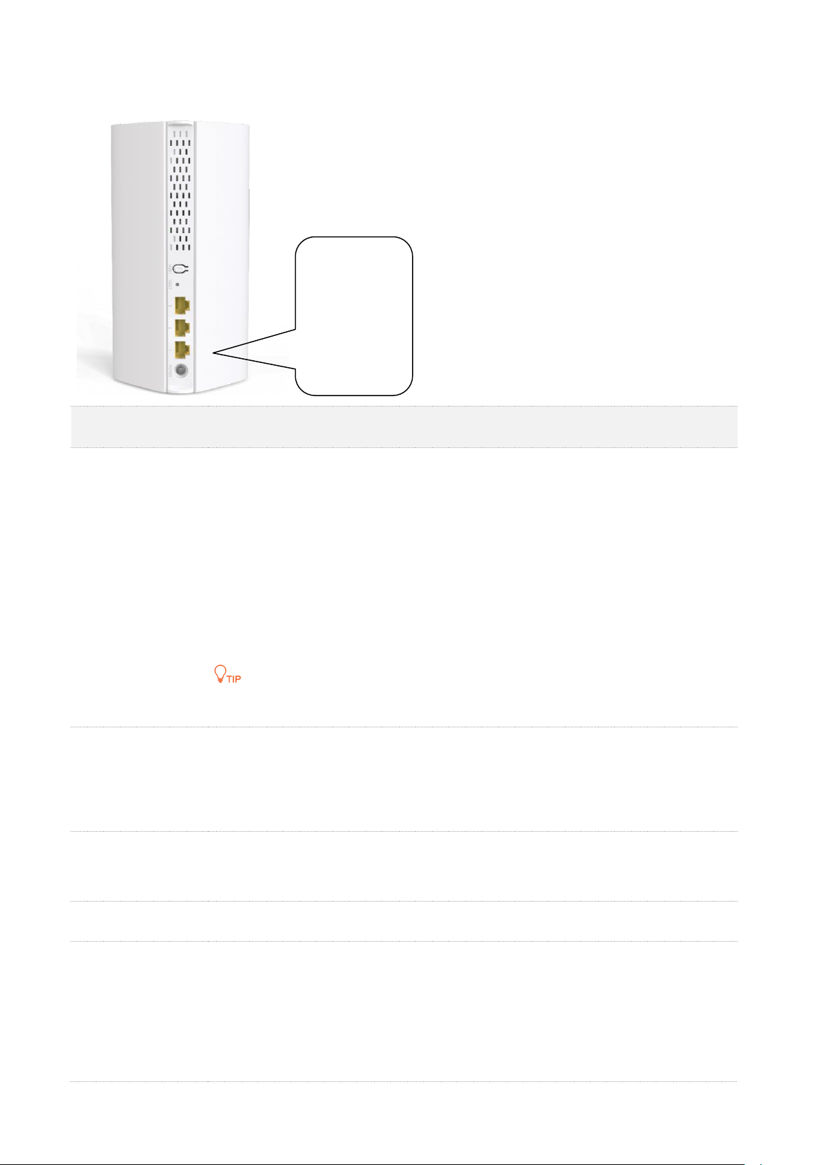
MX15 Pro&EX15 Pro&MX21 Pro&EX21 Pro
Jack/Port/Button
Description
RESET
Reset button.
When the device completes startup, hold down this button using a needle-like item
(such as a pin) for about 8 seconds, and then release it when the LED indicator blinks
red fast. If the LED indicator blinks green slowly, the device is reset successfully.
MESH
Mesh button.
−
As a networking button: Press this button on this device for about 1 to 3
seconds. The LED indicator blinks green fast, which indicates the device is
searching for another device to form a network. Within 2 minutes, press the
MESH button of another device for 1 to 3 seconds to negotiate with this
device.
−
As a de-networking button: Press this button for about 8 seconds and release
it when the LED indicator blinks red fast. The node is restored to factory
settings, and also removed from the network and no longer automatically
joins in again.
Do not hold down the MESH button for 8 seconds unless necessary.
RESET
MESH
3
2
1
POWER
Page 19

Document version: V1.1
8
Jack/Port/Button
Description
1/2/3
WAN/LAN auto-adaptive port.
You can connect to any port and the Mesh device will automatically determine how
the port is used.
When the IPTV function is enabled, you need to configure the IPTV port in IPTV.
POWER
Power jack.
1.2.3 Label
The bottom label shows the login IP address, MAC address, serial number, SSID, and password of
the device. The following figure shows the label of MX15 Pro as an example:
Model: Specifies the device model.
Power: Specifies the power of the device.
Login Address/IP Address: Specifies the default address used to log in to the web UI of the device.
FCC ID: Specifies the Federal Communications Commission Identification number of the device.
SSID: Specifies the default Wi-Fi name of the device.
Password: Specifies the default Wi-Fi password of the device.
MAC: Specifies the MAC address of the LAN port of the device.
SN: Specifies the serial number required if you need technical assistance to repair your device.
Page 20

Document version: V1.1
9
2 Web UI operations
(computer)
This chapter introduces all functions and operations available on the web UI (computer), including:
−
Quick setup
−
Brief introduction to the Web UI
−
Network status
−
Internet settings
−
Wi-Fi settings
−
Client management
−
Parental control
−
More advanced settings
Some functions and operations are also available on the Tenda WiFi App and web UI (mobile client).
For details, see App operations and Web UI operations (mobile client).
Page 21

Document version: V1.1
10
2.1 Quick setup
The device kit you purchased includes multiple devices. You can choose one of them to work as the
primary node and others as the secondary nodes to extend your network. This section describes
how to connect the devices and enable internet access through the quick setup wizard. It contains
the following sections:
−
Connect your primary node
−
Connect your primary node to the internet
−
Extend your network
2.1.1 Connect your primary node
Connect your primary node with a modem
To connect your primary node with a modem:
Step 1
Power off your modem.
Step 2
Use the included Ethernet cable to connect the WAN port of the primary node to your
modem.
The WAN port of the primary node may vary with models.
−
For MX3/EX3, connect to the WAN/LAN port.
−
For MX6/EX6/MX12/EX12, connect to the WAN/LAN1 port.
−
For MX15 Pro/EX15 Pro/MX21 Pro/EX21 Pro, connect to any of 1, 2 and 3 ports.
Step 3
Power on your modem.
Step 4
Power on the primary node, and wait until the LED indicator blinks green.
---End
Page 22

Document version: V1.1
11
Connect your primary node without a modem
To directly connect your primary node without a modem:
Step 1
Ensure that the network connection status of your Ethernet device is normal.
Step 2
Use an Ethernet cable to connect the WAN port of the primary node to the LAN port of
the Ethernet device.
The WAN port of the primary node may vary with models.
−
For MX3/EX3, connect to the WAN/LAN port.
−
For MX6/EX6/MX12/EX12, connect to the WAN/LAN1 port.
−
For MX15 Pro/EX15 Pro/MX21 Pro/EX21 Pro, connect to any of 1, 2 and 3 ports.
Step 3
Power on the primary node, and wait until the LED indicator lights solid green.
---End
2.1.2 Connect your primary node to the internet
After connecting your primary node, you can complete quick setup for internet access by following
the instructions on the web UI wizard. This wizard only occurs upon your first setup.
To connect your primary node to the internet through the quick setup wizard:
Step 1
Use an Ethernet cable to connect your computer to the LAN port of the primary node.
The LAN port of the primary node may vary with models.
−
For MX3/EX3, connect to the LAN port.
−
For MX6/EX6/MX12/EX12, connect to the LAN2 or LAN3/IPTV port.
−
For MX15 Pro/EX15 Pro/MX21 Pro/EX21 Pro, connect to any of 1, 2 and 3 ports.
Step 2
Start a browser on the computer and enter tendawifi.com in the address bar to access
the web UI.
Page 23

Document version: V1.1
12
Step 3
Click Start Now.
The system will automatically detect your internet connection type.
−
If the internet detection is normal, the following page is displayed and you can
continue the setup in Step 4.
−
If the internet detection fails, the following page is displayed. Rectify the fault as
instructed on the page, and click Detect Again.
Page 24

Document version: V1.1
13
Step 4
Set ISP Type, Internet Connection Type and other parameters as required. Then, click
Next.
For MX3/EX3/Mesh3X, you can click Import PPPoE user name and password from your original router
to see how to import PPPoE user name and password from your original router. After you import your
PPPoE user name and password into the router, ISP Type, Internet Connection Type, PPPoE Username
and PPPoE Password will be set automatically.
The following table describes the parameters displayed on this page.
Page 25

Document version: V1.1
14
Parameter description
Parameter
Description
ISP Type
Specifies the type of your ISP, such as Normal, Russia, Unifi, Maxis, Celcom, Digi and
Manual. Parameters required for each option may differ.
The available options may vary with models. Refer to the product that you purchased.
Refer to the following to choose your connection type:
−
Normal, Unifi, Maxis, Celcom and Digi: Select these options when your ISP
provides no setup information, except for the PPPoE user name and
password, or static IP address information.
−
Russia: Select this option when your ISP provides dual access information,
such as PPTP, L2TP connection information.
−
Manual: Select this option when your ISP provides VLAN ID information,
besides the PPPoE user name and account, or static IP address.
If you are still not sure, contact your ISP for reference.
Internet Connection
Type
Specifies how your Mesh device connects to the internet, including:
−
PPPoE, Russia PPPoE: Select this type if you access the internet using the
PPPoE account and PPPoE password. Russia PPPoE is available only when
you set ISP Type to Russia.
−
Dynamic IP: Select this type if you can access the internet by simply plugging
in an Ethernet cable.
−
Static IP: Select this type if you want to access the internet using fixed IP
information.
−
Russia PPTP, Russia L2TP: These types are available when ISP Type is set to
Russia. If you select Russia PPTP or Russia L2TP, the VPN function will be
disabled.
PPPoE Username
When the internet connection type is PPPoE, you need to enter the user name and
password provided by your ISP to access the internet.
PPPoE Password
IP Address
When the internet connection type is static IP, you need to enter the fixed IP address
information provided by your ISP.
If your ISP provides only one DNS server, you can leave Secondary DNS blank.
Subnet Mask
Default Gateway
Primary DNS
Secondary DNS
Address Type/DHCP
When you set ISP Type to Russia, this parameter is required.
It specifies the method for obtaining IP address information to access the “local”
network, where the internal resources of the ISP are located.
Page 26

Document version: V1.1
15
Parameter
Description
DNS Settings
This parameter is required only when ISP Type is set to Russia. It specifies how the
WAN port DNS address is obtained, which is Auto by default.
−
Auto: The Mesh device obtains a DNS server address from the DHCP server
of the upstream network automatically.
−
Manual: The DNS server address is configured manually.
Server IP
Address/Domain
Name
These parameters are used for setting up internet access in the dual access network
environment. When you set ISP Type to Russia and Internet Connection Type to
Russia PPTP or Russia L2TP, these parameters are required.
User Name
Password
Area
When you set ISP Type to Maxis, Celcom or Digi, this parameter is required.
It specifies the ISP area, including:
−
Maxis: Maxis and Maxis-Special
−
Celecom: Celcom West(BIZ), Celcom West(HOME), Celcom East(BIZ) and
Celcom East(HOME)
−
Digi: Digi-TM, Digi, Digi-CT Sabah and Digi-TNB
Internet VLAN ID
When you select Manual for ISP Type, you can configure these parameters.
Internet VLAN ID is required, while IPTV VLAN ID is optional. Blank VLAN ID indicates
that the IPTV function is disabled.
IPTV VLAN ID
Step 5
Set the Wi-Fi name, Wi-Fi password and login password as required, and click Next.
−
To use the same password for Wi-Fi access and web UI login, keep Set WiFi password to router
login password selected, which is the default setting.
−
To use different passwords for Wi-Fi access and web UI login, deselect Set WiFi password to
router login password, and set Wi-Fi Name and WiFi Password for Wi-Fi login and Login
Password and Confirm Password for web UI login.
−
If you do not want to use a password, select Not encrypted. In this case, any client can access
the network without a password. Selecting this option is not recommended as it leads to low
network security. This option is only available for some models. Refer to the product that you
purchased.
Page 27

Document version: V1.1
16
Step 6
If the following information is displayed, the quick setup for internet access is finished.
Click Complete.
---End
Now you can access the internet with:
−
Wired devices: Connect to the LAN ports of your node
−
Wireless devices: Connect to your Wi-Fi network using the Wi-Fi name and password
you set
Page 28

Document version: V1.1
17
2.1.3 Extend your network
Upon your first login, the information instructing how to extend the network with secondary nodes
in the same kit is displayed. To extend the network with other nodes, see Add a node.
To extend your network with secondary nodes in the same kit:
Step 1
Connect secondary nodes by following the instructions displayed.
When the LED indicators of secondary nodes light solid green, the networking is
successful.
Step 2
Relocate the secondary nodes to a proper position.
−
Ensure that the distance between any two nodes is less than 10 meters.
−
Keep your nodes away from electronics with strong interference, such as microwave ovens,
induction cookers, and refrigerators.
−
Place the nodes in a high position with few obstacles.
Step 3
Power on the secondary nodes again. Wait until these LED indicators blink green slowly.
If the LED indicator of any secondary node blinks green slowly for more than 3 minutes, move it closer
to the primary node.
Step 4
Observe the LED indicators of the secondary nodes until the LED indicators light one of
the following colors:
Solid green
Networking succeeds. Excellent connection quality.
Solid yellow
Networking succeeds. Fair connection quality.
Solid red
Networking succeeds. Poor connection quality.
If any secondary node's LED indicator lights solid red, relocate it by repeating Steps 2 to 4.
---End
Now you can access the internet with:
−
Wired devices: Connect to the LAN ports of your nodes
−
Wireless devices: Connect to your Wi-Fi network using the Wi-Fi name and password
you set (All nodes share the same Wi-Fi name and password.)
Page 29

Document version: V1.1
18
2.2 Web UI (computer)
This section introduces basic information of the web UI (computer), including:
−
Log in to the web UI
−
Log out of the web UI
−
Change the language
2.2.1 Log in to the web UI (computer)
To log in to the web UI (computer), perform the following steps:
Step 1
Use an Ethernet cable to connect your computer to the LAN port of the primary node.
The LAN port of the primary node may vary with models.
−
For MX3/EX3, connect to the LAN port.
−
For MX6/EX6/MX12/EX12, connect to the LAN2 or LAN3/IPTV port.
−
For MX15 Pro/EX15 Pro/MX21 Pro/EX21 Pro, connect to any of 1, 2 and 3 ports.
Step 2
Start a browser on the computer and enter tendawifi.com in the address bar to access
the web UI.
Step 3
Enter your login password, and click Login.
−
If this is your first login and internet access is not configured, go to Connect your primary node to
the internet.
−
The login password is the one that you specified in Step 5 in Connect your primary node to the
internet. It is case-sensitive. If you forgot the login password, go to Forgot my password.
---End
Page 30

Document version: V1.1
19
2.2.2 Log out of the web UI (computer)
If you log in to the web UI (computer) of the Mesh device and perform no operation within 5
minutes, the Mesh device logs you out automatically. You can also log out by clicking Exit at the
top right corner of the web UI.
2.2.3 Change the language
The default language displayed is English. You can select another language from the drop-down list
in the upper right corner.
Page 31

Document version: V1.1
20
2.3 Network status
This module allows you to view basic network information, including controller and agent
information, and perform quick setup on nodes, such as adding a node, one-click optimization,
rebooting all nodes, and turning on/off all indicators.
This section includes the following parts:
−
Network status
−
Network topology
2.3.1 Network status
To view the network status:
Step 1
Log in to the web UI.
Step 2
Choose Network Status.
The following page is displayed.
---End
The following table describes the information displayed under Network Status.
No.
Description
1
Indicates the internet connection status.
−
Connected: The primary node is connected to the internet successfully.
−
Disconnected: The primary node is disconnected from the internet.
2
The information here varies depending on the internet connection status.
−
X.xx Mbps: The internet is connected successfully, and the real-time upload and
download speeds are displayed, as shown in the figure above.
−
Connecting: The primary node is connecting to the internet.
−
Other information (for example, No Ethernet cable is connected to the WAN port): The
internet connection failed. Click the prompt message to view tips for troubleshooting. If
the problem persists, contact technical support for help.
Page 32

Document version: V1.1
21
No.
Description
3
Indicates the number of available Wi-Fi networks.
4
Indicates the Wi-Fi name and frequency band.
5
Indicates the number of clients connected in the network, including secondary Mesh nodes.
2.3.2 Network topology
To view the basic information of the network topology and perform quick operations:
Step 1
Log in to the web UI.
Step 2
Choose Network Status.
The following page is displayed.
---End
The following table describes the information displayed under Network Topology.
No.
Description
1
Explains the node status indicated by different colors.
−
Green: The node is connected and the networking signal is good.
−
Yellow: The node is connected and the networking signal is fair.
−
Red: The node is connected and the networking signal is poor.
−
Grey: The node is offline.
2
Form a network topology. For details, see Controller information and Agent information.
3
4
Used to Add a node.
5
Used for One-click optimization.
Page 33

Document version: V1.1
22
No.
Description
6
Used to Reboot all nodes.
7
Used to Turn on/off all indicators.
Controller information
To view the information about and perform quick operations on the controller (primary node) and
clients in the network:
Step 1
Log in to the web UI.
Step 2
Choose Network Status. Then, click under Network Topology.
The following dialog box is displayed.
---End
Page 34

Document version: V1.1
23
The following table describes the information and operation shortcuts displayed under Node Info.
No.
Description
1
This area displays the information and operation shortcuts of the primary node, including:
−
Node Name: Indicates the name of primary node, which is Controller by default. You can
change the name by clicking beside Primary Node.
−
IP Address: Indicates the IP address of the LAN port of the primary node.
−
MAC Address: Indicates the MAC address of the LAN port of the primary node.
−
Uptime: Indicates the network connection time of the primary node.
−
Ethernet Port Status: Indicates the status of the Ethernet ports of the primary node.
Currently, this parameter is only available for Mesh15XP, MX15 Pro, EX15 Pro,
Mesh21XEP, MX21 Pro and EX21 Pro.
: Indicates that the port is connected and used as a WAN port.
: Indicates that the port is connected and used as a LAN port.
: Indicates that the port is connected and used as an IPTV port.
: Indicates that the port is not connected.
−
Connection Quality: Shows the connection signal strength with the primary node. You
can hover your mouse over to see the strength value. This parameter is only
available for some models. Refer to the product that you purchased.
−
LED On/Off: Provides a button for turning on/off the LED indicator of the
primary node. You can use this function to check which device you are operating. Turn
on/off all indicators prevails to this operation.
−
Operation: Provides a button for rebooting the primary node and a button
for resetting the primary node.
Resetting clears all configurations and restores the device to factory settings. Please operate with
caution.
Page 35

Document version: V1.1
24
No.
Description
2
This area displays the information and operation shortcuts of main network clients, including:
−
Client name: You can change the client name by clicking .
−
IP Address: Indicates the IP address of the client.
−
MAC Address: Indicates the MAC address of the client.
−
Uptime: Indicates the network connection time of the client and the networking mode,
such as Wired, 2.4G and 5G.
−
Current Speed: Indicates the real-time upload and download speeds.
−
Negotiation Speed: Indicates the speed of negotiation.
−
Bandwidth Control: Used to set the maximum upload and download speeds, including:
Unlimited: The speed is not limited.
128 KB/s, 256 KB/s: The maximum speed is limited to 128 KB/s or 256 KB/s.
Custom (KB/s): You can set any speed in the range of 1 KB/s to 256000 KB/s.
−
Operation:
Local Host: Indicates that this client is the local host, which is the computer
connected to the primary node in this example. For the local host, no operation is
available here.
Add to blacklist: Used to blacklist a client. Once blacklisted, the client cannot
access the internet through the Mesh system.
3
This area displays the information and operation shortcuts of offline clients, including:
−
Client name: You can change the client name by clicking .
−
MAC address: Indicates the MAC address of the client.
−
Current Speed: Unavailable.
−
Negotiation Speed: Displays the speed of negotiation.
−
Operation: Provides an Add to blacklist button for blacklisting clients. Once blacklisted,
the client cannot access the internet through the Mesh system.
A maximum of 30 offline clients can be displayed here. A client will be automatically deleted from
the list if it is offline for 3 days. A client is displayed under Offline Device after it is disconnected
from the network for 90 seconds (wired client)/60 seconds (wireless client).
Agent information
To view the information about and perform quick operations on the agents (secondary nodes) in
the network:
Step 1
Log in to the web UI.
Step 2
Choose Network Status. Then, click under Network Topology.
The following dialog box is displayed.
Page 36

Document version: V1.1
25
---End
The following table describes the information and operation shortcuts displayed under Node Info.
Parameter
Description
Node Name
Indicates the name of a secondary node, which is Agent by default. You can change
the name by clicking .
IP Address
Indicates the IP address of a secondary node.
MAC Address
Indicates the MAC address of a secondary node.
Uptime
Indicates the network connection time of the secondary node and the networking
mode, such as Wired, 2.4G and 5G.
Connection Quality
Shows the connection signal strength with the primary node. You can hover your
mouse over to see the strength value.
LED On/Off
Provides a button for turning on/off the LED indicator of the secondary
node. You can use this function to check which device you are operating. Turn on/off
all indicators prevails to this operation.
Operation
The available options include:
: Used to reboot the node.
: Used to remove the node. Removing a node will narrow the Wi-Fi coverage,
and the removed node will no longer join the current network automatically. To add a
removed node again, go to Add a node.
Add a node
−
The node to be added must support the EasyMesh or Xmesh protocol.
−
The node to be added must be located within the signal coverage of the primary node.
−
A maximum of nine nodes can be added to a Mesh network.
To add a node:
Step 1
Log in to the web UI.
Page 37

Document version: V1.1
26
Step 2
Choose Network Status. Then, click under Network Topology.
Step 3
Follow the instructions displayed.
If the LED indicator of new node lights solid on and the new node is displayed in Network
Topology, the node is added successfully.
---End
If you cannot add a node by following the preceding instructions, try the following two methods by
clicking Scanning networking or Wired networking shown in the following figure:
◼
To scan a new node:
Step 1
Click Scanning networking.
Page 38

Document version: V1.1
27
Step 2
Select a node, and click Add.
Step 3
Wait until the ongoing process is complete.
If the LED indicator of new node lights solid on and the new node is displayed in Network
Topology, the node is added successfully.
---End
Page 39

Document version: V1.1
28
◼
To perform wired networking:
Click Wired networking and follow the instructions displayed.
If the LED indicator of new node lights solid on and the new node is displayed in Network Topology,
the node is added successfully.
One-click optimization
To optimize the Wi-Fi network with one click:
Step 1
Log in to the web UI.
Step 2
Choose Network Status. Then, click under Network Topology.
Step 3
Click OK.
After you click OK, the Wi-Fi network is disabled and it takes some time for the
optimization process. Wait until the network is enabled again.
---End
Reboot all nodes
To reboot all nodes by one click:
Step 1
Log in to the web UI.
Step 2
Choose Network Status. Then, click under Network Topology.
Step 3
Click Reboot. Wait until all nodes are restarted.
---End
Page 40

Document version: V1.1
29
Turn on/off all indicators
This operation prevails to LED indicator operations for each node and Smart power saving.
To turn on/off indicators of all nodes by one click:
Step 1
Log in to the web UI.
Step 2
Choose Network Status. Then, click or under Network Topology.
The indicators turn on/off immediately.
---End
Page 41

Document version: V1.1
30
2.4 Internet settings
By configuring the internet settings, you can achieve shared internet access (IPv4) for multiple
users within the LAN.
If you are configuring the Mesh device for the first time or after restoring it to factory settings,
refer to Connect your primary node to the internet to configure the internet access. After that, you
can change the internet settings by following the instructions in this chapter.
This section includes the following parts:
−
Overview
−
Access the internet with a PPPoE account
−
Access the internet through a dynamic IP address
−
Access the internet with a set of static IP address information
−
Set up dual access connection
2.4.1 Overview
Parameters for internet access are provided by your ISP. Contact your ISP for any doubt.
To access the internet settings page, log in to the web UI, and choose Internet Settings.
The following page is displayed.
Page 42

Document version: V1.1
31
The following table describes the parameters displayed on this page.
Parameter description
Parameter
Description
Network Status
Indicates the internet connection status.
−
Connected: The internet connection is successful.
−
Other information (for example, No Ethernet cable is connected to the
WAN port): The internet connection failed. Perform troubleshooting
according to the tips displayed.
Uptime/Connected
time
Indicates the network connection time of the Mesh device.
ISP Type
See Parameter description in Connect your primary node to the internet.
Internet Connection
Type
PPPoE Username
PPPoE Password
IP Address
Subnet Mask
Gateway
Primary DNS
Secondary DNS
Address Type
DNS Settings
Server IP
Address/Domain
Name
User Name
Password
Area
Internet VLAN ID
Page 43

Document version: V1.1
32
Parameter
Description
IPTV VLAN ID
Server Name
Displayed after you click Advanced if the connection type is PPPoE.
They specify the PPPoE server name and PPPoE service name of the broadband
service that you purchased.
If you obtain the service name and server name from your ISP when purchasing the
broadband service, you can change them on this page after completing the internet
settings. Otherwise, keep the default settings.
Service Name
MTU
Displayed after you click Advanced.
It specifies the largest data packet transmitted by a network device. Do not change
the value unless:
−
Your ISP or our technical support suggests you change it when you have
problems connecting to your ISP or other internet services.
−
You use VPN and encounter serious performance problems.
−
You used a program to optimize MTU for performance reasons, and now
you have connectivity or performance problems.
A wrong/improper MTU value may cause internet communication problems. For
example, you may be unable to access certain Websites, frames within Websites,
secure login pages, FTP or POP servers.
The MTU value range is as follows:
−
When the internet connection type is PPPoE, the default value is 1480. Its
allowed range is 1280 to 1492.
−
When the internet connection type is dynamic IP or static IP, the default
value is 1500. Its allowed range is 1280 to 1500.
−
When the internet connection type is PPTP/L2TP, the default value is 1400.
Its allowed range is 1280 to 1460.
MAC Address Clone
Used to clone and change the MAC address of the WAN port of primary node.
If the primary node cannot be connected to the internet after internet settings, the
reason may be that the ISP binds internet access information to a MAC address. At
this point, perform MAC address clone and try to surf the internet.
−
Default MAC: Keep the factory setting of MAC address.
−
Clone Local Host MAC: Set the MAC address of the Mesh device to the same
as that of the device which is configuring the Mesh device.
−
Custom: Manually set a MAC address.
Custom MAC
Address
Required when you select Custom for MAC Address Clone under Advanced. You can
enter the customized MAC address here.
Page 44

Document version: V1.1
33
2.4.2 Access the internet with a PPPoE account
If the ISP provides you with the PPPoE user name and password, you can choose this connection
type to access the internet. The application scenario is shown below.
To access the internet with a PPPoE account:
Step 1
Log in to the web UI, and choose Internet Settings.
Step 2
Set ISP Type.
If you select Manual for ISP Type, enter Internet VLAN ID and IPTV VLAN ID (if any) provided by your
ISP. Blank VLAN ID indicates that the IPTV function is disabled.
Step 3
Set Internet Connection Type to PPPoE.
Step 4
Enter the PPPoE Username and PPPoE Password provided by your ISP.
Step 5
Click Connect.
Wait until the network status changes to Connected, then you can access the internet.
Modem (such as optical modem)
Page 45

Document version: V1.1
34
---End
If there is no response from the remote server, troubleshoot as prompted under Network Status on
the Internet Settings page.
2.4.3 Access the internet through a dynamic IP address
Generally, accessing the internet through a dynamic IP address is applicable in the following
situations:
−
Your ISP does not provide the PPPoE user name and password, or any other
information including IP address, subnet mask, default gateway and DNS server.
−
You already have a router with internet access and want to add another router.
The application scenario is shown below.
To access the internet through dynamic IP address:
Step 1
Log in to the web UI, and choose Internet Settings.
Step 2
Set ISP Type.
If you select Manual for ISP Type, enter Internet VLAN ID and IPTV VLAN ID (if any) provided by your
ISP. Blank VLAN ID indicates that the IPTV function is disabled.
Step 3
Set Internet Connection Type to Dynamic IP.
Step 4
Click Connect.
Smart home gateway
Page 46

Document version: V1.1
35
Wait until the network status changes to Connected, then you can access the internet.
---End
2.4.4 Access the internet with a set of static IP address
information
When your ISP provides you with information including IP address, subnet mask, default gateway
and DNS server, you can choose this connection type to access the internet.
To access the internet with a set of static IP address information:
Step 1
Log in to the web UI, and choose Internet Settings.
Step 2
Set ISP Type.
If you select Manual for ISP Type, enter Internet VLAN ID and IPTV VLAN ID (if any) provided by your
ISP. Blank VLAN ID indicates that the IPTV function is disabled.
Step 3
Set Internet Connection Type to Static IP.
Step 4
Set IP Address, Subnet Mask, Gateway and Primary DNS, and Secondary DNS with the
information provided by your ISP.
Step 5
Click Connect.
Page 47

Document version: V1.1
36
Wait until the network status changes to Connected, then you can access the internet.
---End
2.4.5 Set up dual access connection
In countries like Russia, the ISP may require you to set up dual access. One is for access to the
internet through PPPoE, PPTP or L2TP, and the other is for access to the “local” resources where
the ISP is located through DHCP or static IP address. If your ISP provides such connection
information, you can set up dual access to access the internet.
To set up dual access connection:
Step 1
Log in to the web UI, and choose Internet Settings.
Step 2
Set ISP Type to Russia.
Step 3
Set Internet Connection Type, which is Russia PPTP in this example, and fill in required
parameters.
Page 48

Document version: V1.1
37
Step 4
Set Address type, and fill in required parameters.
Step 5
Click Connect.
Wait until the network status changes to Connected, then you can access the internet.
---End
Page 49

Document version: V1.1
38
2.5 Wi-Fi settings
This section introduces basic Wi-Fi settings, including changing the Wi-Fi name, password and
encryption mode, and separating and unifying the 2.4 GHz, 5 GHz and 6 GHz networks.
The 6 GHz WiFi network is only supported by MX21 Pro/EX21 Pro/Mesh21XEP.
This section includes the following parts:
−
Basic settings
−
Separate the Wi-Fi networks
−
Unify the Wi-Fi networks
−
Disable or Enable the WiFi networks
2.5.1 Basic settings
To access the Wi-Fi settings page, log in to the web UI, and choose WiFi Settings.
On this page, you can configure basic WiFi parameters, such as the WiFi name and password.
The following table describes the parameters displayed on this page.
Page 50

Document version: V1.1
39
Parameter description
Parameter
Description
Unify 2.4 GHz & 5
GHz
Used to enable or disable the Unify 2.4 GHz & 5 GHz function.
When this function is enabled, the 2.4 GHz and 5 GHz Wi-Fi networks share the same
SSID and password. WiFi-enabled clients connected to it will use the frequency with
better connection quality. For details, see Separate the Wi-Fi networks and Unify the
Wi-Fi networks.
If any device that supports 2.4 GHz network only needs to connect to the Wi-Fi
network, do not enable this function.
Unify 2.4 GHz & 5
GHz & 6 GHz
Used to enable or disable the Unify 2.4 GHz & 5 GHz & 6 GHz function. It is available
only for MX21 Pro/EX21 Pro/Mesh21XEP.
When this function is enabled, the 2.4 GHz, 5 GHz and 6 GHz Wi-Fi networks share the
same SSID and password. WiFi-enabled clients connected to it will use the frequency
with better connection quality. For its operations, see Separate the Wi-Fi networks and
Unify the Wi-Fi networks for reference.
If any device that supports 2.4 GHz network only needs to connect to the Wi-Fi
network, do not enable this function.
WiFi Enable/2.4
GHz WiFi/5 GHz
WiFi/6 GHz WiFi
Used to enable or disable the Wi-Fi networks.
−
WiFi Enable is displayed when Unify 2.4 GHz & 5 GHz or Unify 2.4 GHz & 5
GHz & 6 GHz is enabled.
−
2.4 GHz WiFi, 5 GHz WiFi or 6 GHz WiFi is displayed when Unify 2.4 GHz & 5
GHz or Unify 2.4 GHz & 5 GHz & 6 GHz is disabled.
WiFi Name
Specifies the Wi-Fi network name (SSID) of the corresponding Wi-Fi network.
Page 51

Document version: V1.1
40
Parameter
Description
Security
Specifies the encryption mode supported by the Mesh device, including:
−
Not encrypted: Indicates that the Wi-Fi network is not encrypted and any
clients can access the network without a password. This option is not
recommended as it leads to low network security. It is available for the 2.4
GHz and 5 GHz Wi-Fi networks.
−
WPA2-PSK (Recommended): The network is encrypted with WPA2-PSK/AES.
It is available for the 2.4 GHz and 5 GHz Wi-Fi networks.
−
WPA3-SAE/WPA2-PSK: The network is encrypted with both WPA3-SAE and
WPA2-PSK, improving both security and compatibility. This option is only
available for some models. Refer to the product you purchased.
−
WPA3-SAE: The network is encrypted with WPA3-SAE. It is available for only
the 6 GHz Wi-Fi network.
−
OWE: The network is encrypted with the Opportunistic Wireless Encryption
(OWE) mode. It is available for only the 6 GHz Wi-Fi network. With this option
selected, clients can access the 6 GHz WiFi network without the WiFi
password while the data exchanged will still be encrypted.
WPA3-SAE is the upgraded version of WPA2-PSK. If your WiFi-enabled client does not
support WPA3-SAE, or you get poor WiFi experience, it is recommended to use
WPA2-PSK (Recommended).
WiFi Password
Specifies the password for connecting to the Wi-Fi network. You are strongly
recommended to set a Wi-Fi password for security.
It is recommended to use the combination of numbers, uppercase letters, lowercase
letters and special symbols in the password to enhance the security of the Wi-Fi
network.
Page 52

Document version: V1.1
41
2.5.2 Separate the Wi-Fi networks
The Mesh device supports 2.4 GHz, 5 GHz and 6 GHz Wi-Fi networks, which are unified and only
one Wi-Fi name is displayed by default.
The 6 GHz WiFi network is only supported by MX21 Pro/EX21 Pro/Mesh21XEP.
To separate the Wi-Fi names of the networks:
Step 1
Log in to the web UI, and choose WiFi Settings.
Step 2
Disable Unify 2.4 GHz & 5 GHz or Unify 2.4 GHz & 5 GHz & 6 GHz as required.
For MX21 Pro/EX21 Pro/Mesh21XEP:
−
To separate the Wi-Fi names of the three networks, disable Unify 2.4 GHz & 5 GHz & 6 GHz.
−
To separate only the 6 GHz Wi-Fi name, enable Unify 2.4 GHz & 5 GHz but disable Unify 2.4 GHz
& 5 GHz & 6 GHz.
Step 3
(Optional) Enable WiFi Enable or 2.4 GHz WiFi, 5 GHz WiFi and 6 GHz WiFi as required.
This step is only required for MX21 Pro/EX21 Pro/Mesh21XEP.
Step 4
Set WiFi Name, Security and WiFi Password of each WiFi network.
MX15 Pro is used for example here. In this example, the 2.4 GHz Wi-Fi network is named
NOVA_9JK3_A3, the 5 GHz Wi-Fi network is named NOVA_9JK3_A3_5G, and WPA2-PSK
(Recommended) is selected for Security.
Step 5
Click Save.
Page 53

Document version: V1.1
42
The following message is displayed, indicating that the settings are saved successfully.
---End
Now you can connect to the Wi-Fi networks using different Wi-Fi names and passwords.
2.5.3 Unify the Wi-Fi networks
The Mesh device supports 2.4 GHz, 5 GHz and 6 GHz Wi-Fi networks. You can unify their Wi-Fi
names and passwords as required.
The 6 GHz WiFi network is only supported by MX21 Pro/EX21 Pro/Mesh21XEP.To unify the Wi-Fi names
of the networks:
Step 1
Log in to the web UI, and choose WiFi Settings.
Step 2
Enable Unify 2.4 GHz & 5 GHz or Unify 2.4 GHz & 5 GHz & 6 GHz as required.
For MX21 Pro/EX21 Pro/Mesh21XEP:
−
To unify the Wi-Fi names of the three networks, enable Unify 2.4 GHz & 5 GHz & 6 GHz.
−
To unify only the 2.4 GHz and 5 GHz Wi-Fi name, enable Unify 2.4 GHz & 5 GHz but disable Unify
2.4 GHz & 5 GHz & 6 GHz.
Step 3
(Optional) Enable WiFi Enable and 6 GHz WiFi as required.
This step is only required for MX21 Pro/EX21 Pro/Mesh21XEP.
Step 4
Set WiFi Name, Security, and WiFi Password.
MX15 Pro is used for example here. In this example, the Wi-Fi networks are named
NOVA_KF7R_A1 and WPA2-PSK (Recommended) is selected for Security.
Step 5
Click Save.
The following message is displayed, indicating that the settings are saved successfully.
Page 54

Document version: V1.1
43
---End
Now you can connect to the Wi-Fi networks using the same Wi-Fi name and password.
2.5.4 Disable or Enable the WiFi networks
This function is only available for MX21 Pro/EX21 Pro/Mesh21XEP.
◼
To disable some Wi-Fi networks:
Step 1 Log in to the web UI, and choose WiFi Settings.
Step 2 Enable or disable Unify 2.4 GHz & 5 GHz or Unify 2.4 GHz & 5 GHz & 6 GHz as required.
Step 3 Disable WiFi Enable or 2.4 GHz WiFi, 5 GHz WiFi and 6 GHz WiFi as required.
Step 4 Click Save.
In this example, all Wi-Fi networks are separated and 5 GHz and 6 GHz Wi-Fi networks are
disabled.
---End
When the configuration is completed, the corresponding WiFi networks are disabled.
◼
To enable some Wi-Fi networks:
Step 1 Log in to the web UI, and choose WiFi Settings.
Step 2 Enable or disable Unify 2.4 GHz & 5 GHz or Unify 2.4 GHz & 5 GHz & 6 GHz as required.
Step 3 Enable WiFi Enable or 2.4 GHz WiFi, 5 GHz WiFi and 6 GHz WiFi as required.
Step 4
Set WiFi Name, Security, and WiFi Password.
Step 5 Click Save.
Page 55

Document version: V1.1
44
In this example, all Wi-Fi networks are separated enabled.
---End
When the configuration is completed, the corresponding WiFi networks are enabled.
Page 56

Document version: V1.1
45
2.6 Client management
This section describes how to manage your clients, including:
−
View client information
−
Change a client name
−
Add a client to the blacklist
−
Remove a client from the blacklist
−
Delete an offline client
2.6.1 View client information
To view information of clients:
Step 1
Log in to the web UI.
Step 2
Choose Client Management.
−
The information of all clients is displayed by default.
−
To view information of only the clients connected to the controller (primary node), select the
controller from the drop-down list box under Client Management. The controller name is
Controller by default. You can change it in Controller information.
−
To view information of only clients connected to an agent, select the agent from the drop-down
list box on the right. You can change the agent names in Agent information.
The following page is displayed.
---End
The following table describes the information and operation shortcuts displayed under Client
Management.
Page 57

Document version: V1.1
46
Item
Description
Main
Network
Device
Displays the information and operation shortcuts of main network clients, including:
−
Client name: You can change the client name by clicking .
−
IP Address: Indicates the IP address of the client.
−
MAC Address: Indicates the MAC address of the client.
−
Uptime: Indicates the network connection time of the client and the networking mode,
such as Wired, 2.4G and 5G.
−
Current Speed: Indicates the real-time upload and download speeds.
−
Negotiation Speed: Indicates the speed of negotiation.
−
Bandwidth Control: Used to set the maximum upload and download speeds, including:
Unlimited: The speed is not limited.
128 KB/s, 256 KB/s: The maximum speed is limited to 128 KB/s or 256 KB/s.
Custom (KB/s): You can set any speed in the range of 1 KB/s to 256000 KB/s.
−
Operation:
Local Host: Indicates that this client is the local host, which is the computer
connected to the primary node in this example. For the local host, no operation is
available here.
Add to blacklist: Used to blacklist a client. Once blacklisted, the client cannot
access the internet through the Mesh system.
Guest
Device
Displays the information and operation shortcuts of clients connected to the guest network,
including:
−
Current Speed: Indicates the real-time upload and download speeds.
−
Negotiation Speed: Indicates the speed of negotiation.
−
Operation: Provides an Add to blacklist button for blacklisting clients. Once blacklisted,
the client cannot access the internet through the Mesh system.
Offline
Device
Displays the information and operation shortcuts of offline clients, including:
−
Client name: You can change the client name by clicking .
−
MAC Address: Indicates the MAC address of the client.
−
Current Speed: Unavailable.
−
Negotiation Speed: Indicates the speed of negotiation.
−
Operation: Provides an Add to blacklist button for blacklisting clients. Once blacklisted,
the client cannot access the internet through the Mesh system.
A maximum of 30 offline clients can be displayed here. A client is displayed under Offline Device
after it is disconnected from the network for 90 seconds (wired client)/60 seconds (wireless
client). A client will be automatically deleted from this list if it is offline for 3 days.
Blacklist
Displays the information and operation shortcut of blacklisted clients, including:
−
Device Name: Indicates the name of the blacklisted client.
−
MAC Address: Indicates the MAC address of the blacklisted client.
−
Operation: Provides a Remove from the blacklist button for removing clients from the
blacklist.
Page 58

Document version: V1.1
47
2.6.2 Change a client name
You can change the names of all clients connected to the network on the web UI. Here changing
the name of main network client is used as an example. The operations for changing other client
names are similar.
To change the name of a client:
Step 1
Log in to the web UI, and choose Client Management.
Step 2
Click beside the client name.
Step 3
Enter a new name and click .
The new client name is saved.
---End
2.6.3 Add a client to the blacklist
If you find any unknown client connects to your network and you want to block it from accessing
your network, you can blacklist it here. All clients connected to the network can be blacklisted,
except the local host. Here blacklisting a main network client is used as an example. The operations
for blacklisting other clients are similar.
To blacklist a client:
Step 1
Log in to the web UI, and choose Client Management.
Step 2
Click Add to blacklist under Operation in the line of the client to be blacklisted.
Page 59

Document version: V1.1
48
Step 3
Click OK.
The client is removed from the device list and displayed on the blacklist now.
−
If you blacklist a wired client, the wired client will fail to access the network.
−
If you blacklist a wireless client, the wireless client will be kicked offline and cannot connect to
the Mesh device again.
−
The blacklist rule prevails when conflicting with the parent control rule.
---End
2.6.4 Remove a client from the blacklist
If you blacklist a client by mistake, you can remove it from the blacklist.
To remove a client from the blacklist:
Step 1
Log in to the web UI, and choose Client Management.
Step 2
Choose Blacklist.
Page 60

Document version: V1.1
49
Step 3
Click Remove from the blacklist under Operation in the line of the client to be removed
from the blacklist.
Step 4
Click OK.
The client is removed from the blacklist and displayed in Main Network Device, Guest
Device or Offline Device now. It can access the network upon the next connection.
---End
2.6.5 Delete an offline client
You can delete any offline client that is connected to the network before.
To delete an offline client:
Step 1
Log in to the web UI, and choose Client Management.
Step 2
Select the offline client to be deleted, and click Delete on the upper right corner of Offline
Device.
The client you selected is removed from the device list.
The deleted client can be displayed in the device list again upon its next network access.
---End
Page 61

Document version: V1.1
50
2.7 Parental control
This function allows you to configure various parental control rules to control access to certain
websites or block certain clients from accessing the internet.
This section includes the following parts:
−
Create a parental control rule
−
Other operations on the parental control rules
2.7.1 Create a parental control rule
Add a parental control rule
−
The blacklist rule prevails when conflicting with the parent control rule.
−
A maximum of 10 rules can be added.
−
A maximum of 30 clients can be controlled.
To add a parental control rule:
Step 1
Log in to the web UI, and choose Parental Control.
If you did not add a parental control rule before, the following page is displayed.
If you have added parental control rules before, the following page is displayed.
Page 62

Document version: V1.1
51
Step 2
Click Add Parental Control Rule or Add.
Step 3
Set the parameters as required.
A maximum of 10 control periods and 10 URLs can be added.
Step 4
Click Save.
The parental control rule that you set is displayed on the Parental Control page.
---End
The following table describes the parameters under Add Parental Control Rule.
Page 63

Document version: V1.1
52
Parameter description
Parameter
Description
Group Name
Specifies the name of the client group that the parental control rule applies to.
Selected clients
Specifies the clients that the parental control rule applies to.
Time n
Specifies whether the parental control rule takes effect in the specified period.
Add control period
Available when Control Period is enabled. If you want to set multiple periods, click
this button.
URL Filter
Specifies whether the URL filter rule is applied.
−
When it is enabled, Filter mode and URL must be set. The parental
control rule takes effect on specific websites.
−
When it is disabled, the URL filter rule is not applied.
Filter mode
Required when URL Filter is enabled. Two modes are available here.
−
Only block access to listed URLs: The Selected clients are only blocked
from accessing the websites specified by URL.
−
Only allow access to listed URLs: The Selected clients can only access the
websites specified by URL.
URL
Specifies the websites that the Selected clients are blocked from accessing or
allowed to access.
Add URL
Available when URL Filter is enabled. If you want to set multiple URLs, click this
button.
An example of adding parental control rules
Scenario: The final exam for your kid is approaching and you want to configure your kid's internet
access through the Mesh device.
Goal: Your kid cannot access such websites as Facebook, Twitter, YouTube and Instagram from 8:00
to 22:00 on weekends and cannot access the internet at all between 22:00 to 8:00 on weekends
using the computer at home.
Solution: You can configure a parental control rule to reach the goal.
To add such a rule:
Step 1
Log in to the web UI, and choose Parental Control.
Step 2
Click Add Parental Control Rule or Add.
Step 3
Set Group Name, for example, Parental control rule 1.
Step 4
Click beside Selected clients.
The following dialog box is displayed.
Page 64

Document version: V1.1
53
Step 5
Select the clients to which this parental control rule is applied, and click Save.
Step 6
Enable Time 1.
Step 7
Specify the period during which the target websites are blocked, which is 08:00 to 22:00
on weekends in this example.
1.
Click the left field to set Start Time to 08:00 and End Time to 22:00.
2.
Select Sat. and Sun. from the right drop-down list box.
Step 8
Enable URL Filter.
Step 9
Select Only block access to listed URLs for Filter mode.
Step 10
Enter Facebook, Twitter, YouTube, and Instagram for URL.
Page 65

Document version: V1.1
54
Step 11
Click Save.
The following page is displayed, and your kid can access any websites except for
Facebook, Twitter, YouTube and Instagram from 8:00 to 22:00 on weekends and cannot
access the internet at all between 22:00 to 8:00 on weekends.
---End
2.7.2 Other operations on the parental control rules
By default, a parental control rule is enabled after you added it successfully, as shown in the
following figure. You can disable, modify or delete a parental control rule after logging in to the
web UI of the Mesh device and choosing Parental Control.
The following table describes the parameters under Parental Control.
Parameter description
Parameter
Description
Group Name
Specifies the name of the client group that the parental control rule applies to. You
can change the group name by clicking beside it.
Control Period
Specifies the period during which the parental control rule takes effect.
URL Filter
Specifies the websites that are allowed or disallowed to be accessed by the client
group. If Unlimited is displayed, website access is not limited.
Parental Control
Used to enable or disable the parental control rule.
Operation
The available options include:
: Used to edit a parental control rule.
: Used to delete a parental control rule.
Page 66

Document version: V1.1
55
2.8 More
This section describes other settings you may need when using the Mesh device, including:
−
Router information
−
Guest Wi-Fi
−
Working mode
−
IPv6
−
Network diagnosis
−
TR069
−
Smart power saving
−
Advanced Wi-Fi Settings
−
Network settings
−
Advanced
−
System settings
2.8.1 Router information
On this page, you can view the information of the primary node, including Basic information, WAN
port information, and LAN information.
To view the information of the primary node:
Step 1
Log in to the web UI.
Step 2
Choose More > Router Info.
The following page is displayed.
Page 67

Document version: V1.1
56
---End
Page 68

Document version: V1.1
57
Basic information
In this part, you can view basic information about the primary node, as described in the following
table.
Parameter description
Parameter
Description
Product Model
Specifies the model of the primary node.
System Time
Specifies the current system time.
Runtime
Specifies the network connection time of the primary node.
Firmware Version
Specifies the firmware version of the primary node.
Hardware Version
Specifies the hardware version of the primary node.
WAN port information
This part is displayed only in the router mode.
In this part, you can view WAN port information of the primary node, as described in the following
table.
Parameter description
Parameter
Description
Internet Connection Status
Specifies the internet connection status of the WAN port.
Internet Connection Type
Specifies the internet connection type of the WAN port. PPPoE is used as an
example here.
Connected time
Specifies the internet connection time of the primary node.
IP Address
Specifies the WAN IP address of the primary node.
Subnet Mask
Specifies the WAN subnet mask of the primary node.
Default gateway
Specifies the gateway IP address of the primary node.
Primary DNS
Specify the IP address of primary and secondary DNS servers of the primary
node.
Secondary DNS
MAC Address
Specifies the WAN MAC address of the primary node.
Page 69

Document version: V1.1
58
LAN information
In this part, you can view LAN information of the primary node, as described in the following table.
Parameter description
Parameter
Description
IP Address
Specifies the LAN IP address of the primary node, which is also the IP address
for logging in to the web UI of the primary node.
Subnet Mask
Specifies the LAN subnet mask of the primary node.
MAC Address
Specifies the LAN MAC address of the primary node.
Status
Specifies the visibility of the Wi-Fi network.
Wi-Fi Name
Specifies the Wi-Fi name of the respective Wi-Fi network.
Security
Specifies the security mode of the respective Wi-Fi network.
Channel
Specifies the channel that the respective Wi-Fi network works in.
Bandwidth
Specifies the bandwidth of the respective Wi-Fi network.
MAC Address
Specifies the MAC address of the respective Wi-Fi network.
IPv6 status
This part is only displayed when the IPv6 function is enabled. You can view the information of IPv6
connection, including connection type, IPv6 WAN address and IPv6 LAN address.
Parameter
Description
Connection Type
Specifies the IPv6 connection type of the primary node.
Page 70

Document version: V1.1
59
Parameter
Description
IPv6 WAN Address
Specifies the WAN IPv6 address of the primary node.
After the IPv6 function is configured, the WAN port of the primary node obtains
a global unicast IPv6 address or a tunnel address.
Default IPv6 Gateway
Specifies the default IPv6 gateway of IPv6 network.
Primary IPv6 DNS
Specify the primary and secondary DNS server addresses of IPv6 network.
Secondary IPv6 DNS
IPv6 LAN Address
Specifies the LAN IPv6 address of the primary node.
After the IPv6 function is configured, the LAN port of the primary node obtains
a global unicast IPv6 address or a tunnel address, and a link local address.
2.8.2 Guest Wi-Fi
Overview
In this module, you can enable or disable the guest network function and change the Wi-Fi name
and password of the guest network.
A guest network can be set up with a shared bandwidth limit for visitors to access the internet, and
is isolated from the main network. It protects the security of the main network and ensures the
bandwidth of your main network.
To access the configuration page, log in to the web UI of the Mesh device and navigate to More >
Guest WiFi. This function is disabled by default. The following figure shows the Guest WiFi page
with the Guest WiFi function enabled.
Page 71

Document version: V1.1
60
Parameter description
Parameter
Description
Guest WiFi
Used to enable or disable the guest network function.
2.4 GHz WiFi
Name
Specify the Wi-Fi name of the Mesh system's guest network.
You can change the Wi-Fi names (SSIDs) as required. To distinguish the guest network
from the main network, you are recommended to set different Wi-Fi network names.
6 GHz WiFi Name is only available for MX21 Pro/EX21 Pro/Mesh21XEP.
5 GHz WiFi
Name
6 GHz WiFi
Name
WiFi Password
Specifies the password for the Mesh device's two guest networks. It is optional and can be
left blank.
Validity
Specifies the validity period of the guest networks. The guest network function will be
disabled automatically out of the validity period.
Shared
Bandwidth
Allows you to specify the maximum upload and download speed for all clients connected
to the guest networks. By default, the bandwidth is Unlimited.
An example of configuring the guest network
Scenario: A group of friends are going to visit your home and stay for about 8 hours.
Page 72

Document version: V1.1
61
Goal: Prevent the use of Wi-Fi network by guests from affecting the network speed of your
computer for work purposes.
Solution: You can configure the guest network function and let your guests use the guest
networks.
Assume that:
MX15 Pro used
Wi-Fi names for 2.4 GHz and 5 GHz networks: John_Doe and John_Doe_5G
Wi-Fi password for 2.4 GHz and 5 GHz networks: Tenda+245
Shared bandwidth for guests: 8 Mbps
To achieve such a goal:
Step 1
Log in to the web UI
Step 2
Choose More > Guest WiFi.
Step 3
Enable Guest WiFi.
Step 4
Set 2.4 GHz WiFi Name, which is John_Doe in this example.
Step 5
Set 5 GHz WiFi Name, which is John_Doe_5G in this example.
Step 6
Set WiFi Password, which is Tenda+245 in this example.
Step 7
Select a validity period from the Validity drop-down box, which is 8 hours in this example.
Step 8
Set the bandwidth in the Shared Bandwidth drop-down box, which is 8 Mbps in this
example.
Step 9
Click Save.
Page 73

Document version: V1.1
62
During the 8 hours after the configuration, guests can connect their WiFi-enabled devices,
such as smartphones, to John_Doe or John_Doe_5G to access the internet and enjoy the
shared bandwidth of 8 Mbps.
---End
2.8.3 Working mode
You can select a working mode for the Mesh device on this page. The Mesh device can work in the
router mode and access point (AP) mode. Current Mode is displayed after the working mode
currently adopted by the Mesh device, as shown in the following figure. In this example, the
current working mode is router mode.
For users who need to specify the network connection mode, select the router mode. For users
who use an upstream router, select the AP mode.
Router mode
By default, all nodes work in the router mode. All functions are available in this mode. If you want
to switch from the router mode to AP mode, see AP mode.
To switch the working mode from the AP mode to router mode:
Step 1
Log in to the web UI.
Step 2
Choose More > Working Mode.
Step 3
Click Switch Mode.
Page 74

Document version: V1.1
63
Step 4
Click OK.
Step 5
Wait until the devices are restarted.
Step 6
Log in to the web UI of the Mesh device again, and navigate to Network Status to check
whether the router mode is configured successfully as shown below.
Page 75

Document version: V1.1
64
---End
AP mode
When you have a smart home gateway that only provides wired internet access, you can set the
Mesh device to work in AP mode to provide wireless coverage.
When the Mesh device is set to AP mode:
−
Every physical port can be used as a LAN port.
−
The LAN IP address of the Mesh device will be changed. Please log in to the web UI of the Mesh
device by visiting tendawifi.com.
−
Functions, such as bandwidth control and port mapping will be unavailable. Refer to the web UI
for available functions.
To switch the working mode to AP mode:
If you have finished the quick setup wizard before, start a web browser and visit tendawifi.com on a
connected client, then start from Step 3.
Step 1
Log in to the web UI.
Step 2
Choose More > Working Mode.
Step 3
Click Switch Mode.
Page 76

Document version: V1.1
65
Step 4
Click OK.
Step 5
Wait until the devices are restarted.
Step 6
Connect the upstream device, such as a gateway, to any port of the Mesh device.
Page 77

Document version: V1.1
66
Step 7
Log in to the web UI of the Mesh device again, and navigate to Network Status to check
whether the AP mode is configured successfully as shown below.
---End
If there is another network device with the same login domain name (tendawifi.com) as the Mesh
device, log in to the upstream router and find the IP address obtained by the Mesh device in the client
list. Then you can log in to the web UI of the Mesh device by visiting the IP address.
To access the internet, connect your computer to a physical port, or connect your smartphone to
the Wi-Fi network.
You can find the Wi-Fi name and password on the WiFi Settings page. If the network is not
encrypted, you can also set a Wi-Fi password on this page for security.
Smart home gateway
Any port
Any port
Page 78

Document version: V1.1
67
If you cannot access the internet, try the following solutions:
−
Ensure that the original router is connected to the internet successfully.
−
Ensure that your WiFi-enabled clients are connected to the correct Wi-Fi network of the Mesh
device.
−
If the computer connected to the Mesh device cannot access the internet, ensure that the
computer is configured to obtain an IP address and DNS server automatically.
2.8.4 IPv6
This function is only available in the router mode.
The Mesh device can access the IPv6 network of ISPs through three connection types. Choose the
connection type by referring to the following chart.
Scenario
Connection Type
−
The ISP does not provide any PPPoEv6 user name and password and
information about the IPv6 address.
−
You have a router that can access the IPv6 network.
DHCPv6
IPv6 service is included in the PPPoE user name and password.
PPPoEv6
The ISP provides you with a set of information including IPv6 address, subnet mask,
default gateway and DNS server.
Static IPv6 address
Before configuring the IPv6 function, ensure that you are within the coverage of the IPv6 network and
already subscribe to the IPv6 internet service. Contact your ISP for any doubt about it.
DHCPv6
DHCPv6 enables the Mesh device to obtain an IPv6 address from the DHCPv6 server to access the
internet. It is applicable in the following scenarios:
−
The ISP does not provide any PPPoEv6 user name and password and information
about the IPv6 address.
−
You have a router that can access the IPv6 network.
Page 79

Document version: V1.1
68
Configuration procedure:
Step 1
Log in to the web UI.
Step 2
Choose More > IPv6.
Step 3
Enable the IPv6 function.
Step 4
Set Internet Connection Type to DHCPv6.
Step 5
Click Save.
The following message is displayed, indicating that the settings are saved successfully.
---End
Verification:
You can ping an IPv6 website (240c::6666 for example) to check whether the Mesh device accesses
the IPv6 network successfully. The following steps are for your reference.
Step 1
On a computer connected to the Mesh device, press Windows + R to open the Run dialog
box.
Step 2
Type cmd and then click OK to open a regular Command Prompt.
Smart home gateway
Page 80

Document version: V1.1
69
Step 3
Enter ping 240c::6666 and press Enter.
---End
As shown in the following figure, if the number of packets received is not 0, the Mesh device
accesses the IPv6 network successfully.
If the IPv6 network fails, try the following solutions:
−
Ensure that clients connected to the Mesh device obtain their IPv6 address through
DHCP.
−
Consult your ISP for help.
PPPoEv6
If your ISP provides you with the PPPoE user name and password with IPv6 service, you can choose
PPPoEv6 to access the internet.
Configuration procedure:
Step 1
Log in to the web UI.
Step 2
Choose More > IPv6.
Step 3
Enable the IPv6 function.
Step 4
Set Internet Connection Type to PPPoEv6.
Step 5
Set PPPoE Username and PPPoE Password provided by your ISP, and click Save.
Smart home gateway
Page 81

Document version: V1.1
70
Parameter description
Parameter
Description
PPPoE Username
Specify the PPPoE user name and password provided by your ISP.
IPv4 and IPv6 services share the same PPPoE account.
PPPoE Password
The following message is displayed, indicating that the settings are saved successfully.
---End
Verification:
You can ping an IPv6 website (240c::6666 for example) to check whether the Mesh device accesses
the IPv6 network successfully. The following steps are for your reference.
Step 1
On a computer connected to the Mesh device, press Windows + R to open the Run dialog
box.
Step 2
Type cmd and then click OK to open a regular Command Prompt.
Step 3
Enter ping 240c::6666 and press Enter.
---End
As shown in the following figure, if the number of packets received is not 0, the Mesh device
accesses the IPv6 network successfully.
Page 82

Document version: V1.1
71
If the IPv6 network fails, try the following solutions:
−
Ensure that clients connected to the Mesh device obtain their IPv6 address through
DHCP.
−
Consult your ISP for help.
Static IPv6 address
When your ISP provides you with information including IPv6 address, subnet mask, default
gateway and DNS server, you can choose this connection type to access the internet with IPv6.
Configuration procedure:
Step 1
Log in to the web UI.
Step 2
Choose More > IPv6.
Step 3
Enable the IPv6 function.
Step 4
Set the Connection Type to Static IPv6 Address.
Step 5
Enter the required parameters under IPv6 WAN.
Step 6
Click Save.
Parameter description
Parameter
Description
IPv6 Address
Specify the fixed IPv6 address information provided by your ISP.
Page 83

Document version: V1.1
72
Parameter
Description
Default IPv6 Gateway
If your ISP only provides one DNS address, leave the secondary
IPv6 DNS blank.
Primary IPv6 DNS
Secondary IPv6 DNS
The following message is displayed, indicating that the settings are saved successfully.
---End
Verification:
You can ping an IPv6 website (240c::6666 for example) to check whether the Mesh device accesses
the IPv6 network successfully. The following steps are for your reference.
Step 1
On a computer connected to the Mesh device, press Windows + R to open the Run dialog
box.
Step 2
Type cmd and then click OK to open a regular Command Prompt.
Step 3
Enter ping 240c::6666 and press Enter.
---End
As shown in the following figure, if the number of packets received is not 0, the Mesh device
accesses the IPv6 network successfully.
If the IPv6 network fails, try the following solutions:
−
Ensure that you have entered the correct WAN IPv6 address.
−
Ensure that clients connected to the Mesh device obtain their IPv6 address through
DHCP.
−
Consult your ISP for help.
Page 84

Document version: V1.1
73
2.8.5 Network diagnosis
This function is available only for some models. If it is not displayed on your web UI, it is unavailable for
the product that you purchased.
If the network fails or the internet lag is severe, you can choose More > Network Diagnosis to
troubleshoot the fault.
To perform troubleshooting:
Step 1 Log in to the web UI.
Step 2 Choose More > Network Diagnosis.
Step 3 Click Diagnose.
Page 85

Document version: V1.1
74
Step 4 Check the diagnosis result and click Optimize to rectify the faults.
---End
2.8.6 TR069
This function is available only for some models. If it is not displayed on your web UI, it is unavailable for
the product that you purchased.
The CPE WAN Management Protocol (TR-069) allows an Auto-Configuration Server (ACS) from the
internet to perform auto-configuration, provision, collection, and diagnostics to the Mesh device.
This function is disabled by default, and you can enable it as required.
To access the configuration page, Log in to the web UI of the router and choose More > TR069.
Page 86

Document version: V1.1
75
The following table describes the parameters displayed on this page.
Parameter description
Parameter
Description
TR069
Used to enable or disable the Technical Report 069 (TR-069)
function.
ACS
URL
Specifies the domain name of the ACS.
ACS Username
Specifies the user name used to authenticate the Mesh device
when the Mesh device connects to the ACS using the CPE WAN
management protocol.
Page 87

Document version: V1.1
76
Parameter
Description
ACS Password
Specifies the password used to authenticate the Mesh device
when the Mesh device connects to the ACS using the CPE WAN
management protocol.
Periodic
Notification
Used to enable/disable the Mesh device to periodically inform
the ACS.
Notification
Interval
Specifies the interval at which the Mesh device sends messages
to inform the ACS.
Connection
Request
Connection
Request
Username
Specifies the user name used to authenticate the ACS when it
sends the connection request to the Mesh device.
Connection
Request
Password
Specifies the password used to authenticate the ACS when it
sends the connection request to the Mesh device.
Port
Specifies the port used to receive the connection request sent by
the ACS.
STUN
Connection
STUN
Used to enable or disable the Session Traversal Utilities for NAT
(STUN) function, which facilitates the communication between
the Mesh device and the public network when the router is
under a LAN.
STUN Server
Address
Specifies the IP address of the STUN server.
STUN Server Port
Specifies the port of the STUN server.
Page 88

Document version: V1.1
77
2.8.7 Smart power saving
WiFi schedule
This function is available only for some models. If it is not displayed on your web UI, it is unavailable for
the product that you purchased.
Overview
This WiFi Schedule function allows you to disable the Wi-Fi networks of the Mesh device at
specified periods. By default, this function is disabled.
To access the configuration page, log in to the web UI of the Mesh device, and choose More >
Smart Power Saving > WiFi Schedule. The following figure displays the page when the WiFi
Schedule function is enabled.
To make the WiFi schedule work properly, ensure that the system time is synchronized with the
internet time. Refer to System time for configuration.
The following table describes the parameters displayed on this page.
Page 89

Document version: V1.1
78
Parameter description
Parameter
Description
WiFi Schedule
Specifies whether to enable or disable the WiFi Schedule function.
Turn Off at
Specifies the period during which the Wi-Fi networks are disabled.
Repeat
Specifies the days on which the Wi-Fi networks are disabled during the specified period.
Set a WiFi schedule
Assume that you want to disable the Wi-Fi networks from 22:00 to 7:00 every day.
Configuration procedure:
Step 1 Log in to the web UI.
Step 2 Choose More > Smart Power Saving > WiFi Schedule.
Step 3 Enable WiFi Schedule.
Step 4 Set a period for the Wi-Fi networks to be disabled, which is 22:00 – 07:00 in this example.
Step 5 Set the days when the function works, which is Every Day in this example.
Step 6 Click Save.
---End
When the configuration is completed, the Wi-Fi networks will be disabled from 22:00 to 7:00 every
day.
LED indicator
You can turn off the LED indicators of all nodes as required to save power. By default, all the
indicators are turned on.
Turn on/off all indicators prevails to this operation.
Page 90

Document version: V1.1
79
To configure the power saving mode:
Step 1
Log in to the web UI.
Step 2
Choose More > Smart Power Saving > LED Indicator.
Step 3
Set LED Indicator as required.
−
To turn on all indicators, select Enable.
−
To turn off all indicators all the time, select Disable.
−
To turn off all indicators in a specific period, select Schedule Disable and set Turn Off
at to the required period.
Step 4
Click Save.
The following message is displayed, indicating that the settings are saved successfully.
---End
2.8.8 Advanced Wi-Fi settings
Channel & bandwidth
In this section, you are allowed to change the network mode, Wi-Fi channel, and Wi-Fi bandwidth
of 2.4 GHz and 5 GHz Wi-Fi networks.
To access the configuration page, log in to the web UI of the Mesh device, and choose More > WiFi
Settings > Channel & Bandwidth.
To ensure the wireless performance, it is recommended to maintain the default settings on this page
without professional instructions.
Page 91

Document version: V1.1
80
The following table describes the parameters displayed on this page.
Page 92

Document version: V1.1
81
Parameter description
Parameter
Description
Network Mode
Specifies various protocols used for wireless transmission.
The network modes vary with models. Refer to the product you purchased.
2.4 GHz Wi-Fi network supports the following modes:
−
802.11b/g/n: Indicates that devices compliant with the IEEE 802.11b or IEEE
802.11g protocol, and devices working at 2.4 GHz and compliant with the IEEE
802.11n can connect to the 2.4 GHz WiFi network of the Mesh device.
−
802.11b/g/n/ac: Indicates that devices compliant with the IEEE 802.11b or IEEE
802.11g protocol, and devices working at 2.4 GHz and compliant with the IEEE
802.11n or IEEE 802.11 ac protocol can connect to the 2.4 GHz WiFi network of
the Mesh device.
−
802.11b/g/n/ax: Indicates that devices compliant with the IEEE 802.11b or IEEE
802.11g protocol, and devices working at 2.4 GHz and compliant with the IEEE
802.11n or IEEE 802.11ax protocol can connect to the 2.4 GHz Wi-Fi network of
the Mesh device.
−
802.11b/g/n/ac/ax: Indicates that devices compliant with the IEEE 802.11b or
IEEE 802.11g protocol, and devices working at 2.4 GHz and compliant with the
IEEE 802.11n, IEEE 802.11ac or IEEE 802.11ax protocol can connect to the 2.4
GHz WiFi network of the Mesh device.
5 GHz WiFi network supports the following modes:
−
802.11a/n: Indicates that devices compliant with the IEEE 802.11a protocol, and
devices working at 5 GHz and compliant with the IEEE 802.11n can connect to
the Mesh device.
−
802.11a/n/ac: Indicates that devices compliant with the IEEE 802.11a or IEEE
802.11ac protocol, and devices working at 5 GHz and compliant with the IEEE
802.11n can connect to the Mesh device.
−
802.11a/n/ac/ax: Indicates that devices compliant with the IEEE 802.11a or IEEE
802.11ac protocol, and devices working at 5 GHz and compliant with the IEEE
802.11n or IEEE 802.11ax protocol can connect to the Mesh device.
6 GHz Wi-Fi network supports the 802.11ax mode.
−
802.11ax: Indicates that devices working at 6 GHz and compliant with the IEEE
802.11ax can connect to the router.
Channel
Specifies the channel in which the Wi-Fi network works.
By default, the wireless channel is Auto, which indicates that the Mesh device selects a
channel for the Wi-Fi network automatically. You are recommended to choose a channel
with less interference for better wireless transmission efficiency. You can use a third-party
tool to scan the Wi-Fi signals nearby to understand the channel usage situations.
Page 93

Document version: V1.1
82
Parameter
Description
Bandwidth
Specifies the bandwidth of the wireless channel of a Wi-Fi network. Please change the
default settings only when necessary.
The bandwidth varies with models. Refer to the product you purchased.
−
20MHz: Indicates that the channel bandwidth used by the Mesh device is 20
MHz.
−
40MHz: Indicates that the channel bandwidth used by the Mesh device is 40
MHz.
−
20/40MHz: Specifies that a Mesh device can switch its channel bandwidth
between 20 MHz and 40 MHz based on the ambient environment. This option is
available only at 2.4 GHz.
−
80MHz: Indicates that the channel bandwidth used by the Mesh device is 80
MHz. This option is available at 5 GHz and 6 GHz.
−
160MHz: Indicates that the channel bandwidth used by the Mesh device is 160
MHz. This option is available at 5 GHz and 6 GHz.
−
20/40/80MHz: Specifies that a Mesh device can switch its channel bandwidth
among 20 MHz, 40 MHz and 80 MHz based on the ambient environment. This
option is available only at 5 GHz.
−
20/40/80/160MHz: Specifies that a Mesh device can switch its channel
bandwidth among 20 MHz, 40 MHz, 80 MHz and 160 MHz based on the ambient
environment. This option is available at 5 GHz and 6 GHz.
Enable PSC
Specifies whether the Preferred Scanning Channel (PSC) function is enabled. When it is
enabled, the success rate and stability of Wi-Fi 6E wireless terminals connecting to the
router's 6 GHz network will be improved. It is enabled by default.
This option is only available for MX21 Pro/EX21 Pro/Mesh21XEP.
WPS
The WPS function enables WiFi-enabled devices, such as smartphones, to connect to Wi-Fi
networks of the Mesh device without entering the password.
To access the configuration page, log in to the web UI of the Mesh device, and choose More > WiFi
Settings > WPS.
−
This function only applies to WPS-enabled Wi-Fi devices. It is enabled by default and cannot be
disabled.
−
Wi-Fi networks encrypted with WPA3 cannot be connected through WPS.
−
The WPS negotiation times out in 120 seconds. The WPS button is disabled during WPS
negotiation.
To connect devices to the Wi-Fi network using the WPS function:
Step 1
Log in to the web UI.
Page 94

Document version: V1.1
83
Step 2
Choose More > WiFi Settings > WPS.
Step 3
Click the WPS button in the line of the node to which the device is to be connected.
Step 4
Configure the WPS function on your WiFi-enabled devices within 2 minutes. Configuration
on various devices may differ (Example: HUAWEI P10).
1.
Find WLAN settings on your phone.
2.
Tap , and choose WLAN settings.
3.
Choose WPS connection.
Page 95

Document version: V1.1
84
Wait until the WPS negotiation completes. Now the phone is connected to the Wi-Fi
network.
---End
MESH button
You can use the MESH button to network your Tenda devices that support the Mesh function. On
this page, you can enable or disable the MESH button as required.
Page 96

Document version: V1.1
85
−
For information security, do not enable MESH Button when using the Mesh device in public
areas.
−
With this function disabled, you cannot form a network by using the MESH button on the device.
However, you can use the Tenda WiFi App or web UI to add the device to a network.
To enable or disable the MESH button:
Step 1
Log in to the web UI.
Step 2
Choose More > WiFi Settings > MESH Button.
Step 3
Enable or disable MESH Button.
The following message is displayed, indicating that the setting is saved successfully.
---End
2.8.9 Network settings
LAN Settings
To access the configuration page, log in to the web UI of the Mesh device, and choose More >
Network Settings > LAN Settings.
Overview
On this page, you can:
−
Change the LAN IP address and subnet mask of the Mesh device.
−
Change the DHCP server parameters of the Mesh device.
−
The DHCP server can automatically assign IP addresses, subnet masks, gateways and
other information to clients within the LAN. If you disable this function, you need to
manually configure the IP address information on the client to access the internet. Do
not disable the DHCP server function unless necessary.
−
Configure the DNS information assigned to clients.
−
Assign static IP addresses to LAN clients.
Page 97

Document version: V1.1
86
The following table describes the parameters displayed on this page.
Parameter description
Parameter
Description
LAN IP Address
Specifies the LAN IP address of the Mesh device, which is also the
management IP address for logging in to the web UI of the Mesh device.
Subnet Mask
Specifies the subnet mask of the LAN port, used to identify the IP address
range of the local area network.
DHCP Server
Used to enable or disable the DHCP server. Once enabled, the DHCP server
automatically assigns internet parameters such as IP address, subnet mask,
and gateway address to the terminal device. You are recommended to enable
this function.
Address Pool Range
Specifies the range of IP addresses that can be assigned to clients connected
to the Mesh device. The default range is 192.168.0.100 to 192.168.0.200.
Page 98

Document version: V1.1
87
Parameter
Description
Lease Time
Specifies the valid duration of the IP address that is assigned to a client.
When the lease time reaches half, the client will send a DHCP Request to the
DHCP server for renewal. If the renewal succeeds, the lease is renewed based
on the time of the renewal application. If the renewal fails, the renewal
process is repeated at 7/8 of the lease period. If it succeeds, the lease is
renewed based on the time of the renewal application. If it still fails, the client
needs to reapply for IP address information after the lease expires.
It is recommended to keep the default value.
DNS
Specifies whether to allocate another DNS address to the client. When it is
disabled, the LAN port IP address of the Mesh device is used as the DNS
address of the client. When it is enabled, Primary DNS must be set and
Secondary DNS is optional.
This Mesh device has the DNS proxy function.
Primary DNS
Specifies the primary DNS address allocated to the client by the Mesh device.
Make sure that the primary DNS server is the IP address of the correct DNS
server or DNS proxy. Otherwise, you may fail to access the internet.
Secondary DNS
Specifies the secondary DNS server address of the Mesh device used to assign
to the clients. It is optional.
Static IP
Reservation
List
Device Name
Specifies the name of the client.
IP Address
Specifies the IP address reserved for the client.
MAC Address
Specifies the MAC address of the client.
Operation
The available options include:
: Used to edit a static IP address reservation rule.
: Used to delete a static IP address reservation rule.
Assign a static IP address to a LAN client:
Step 1
Log in to the web UI.
Step 2
Choose More > Network Settings > LAN Settings.
Step 3
Click Add in Static IP Reservation List.
Step 4
Set Select Device.
−
You can directly select a client from the drop-down list box, which requires no further
settings on MAC Address and IP Address.
Page 99

Document version: V1.1
88
−
If you select Manual, you need to set Device Name, MAC Address, and IP Address
manually.
Step 5
Click OK.
The following message is displayed, indicating that the settings are saved successfully.
---End
VPN
A Virtual Private Network (VPN) is a private network built on a public network (usually the
internet). This private network exists only logically and has no actual physical lines. VPN technology
is widely used in corporate networks to share resources between corporate branches and
headquarters, while ensuring that these resources are not exposed to other users on the internet.
The typology of a VPN network is shown below.
PPTP server
This series of Mesh devices can function as a PPTP server and accept connections from PPTP
clients.
Page 100

Document version: V1.1
89
To access the configuration page, log in to the web UI of the Mesh device, and choose More >
Network Settings > VPN. This function is disabled by default. When it is enabled, the page is
shown as below.
The following table describes the parameters displayed on this page.
Parameter description
Parameter
Description
PPTP Server
PPTP Server
Used to enable or disable the PPTP server.
When it is enabled, the Mesh device functions as a PPTP server, which
can accept the connections from PPTP clients.
Address Pool
Range
Specifies the IP address range within which the PPTP server can assign
to PPTP clients. It is recommended to keep the default settings.
MPPE Encryption
Used to enable or disable 128-bit data encryption.
The encryption settings should be the same between the PPTP server
and PPTP clients. Otherwise, communication cannot be achieved
normally.
 Loading...