

Page 1

1
AC1900 Enhanced Smart Dual-Band Gigabit WiFi Router
Model: AC18
Page 2

Copyright Statement
© 2016 Shenzhen Tenda Technology Co., Ltd. All rights reserved.
Tenda is a registered trademark legally held by Shenzhen Tenda Technology Co., Ltd. Other
brand and product names mentioned herein are trademarks or registered trademarks of their
respective holders. Copyright of the whole product as integration, including its accessories
and software, belongs to Shenzhen Tenda Technology Co., Ltd. No part of this publication can
be reproduced, transmitted, transcribed, stored in a retrieval system, or translated into any
language in any form or by any means without the prior written permission of Shenzhen
Tenda Technology Co., Ltd.
Disclaimer
Pictures, images and product specifications herein are for references only. To improve internal
design, operational function, and/or reliability, Tenda reserves the right to make changes to
the products without obligation to notify any person or organization of such revisions or
changes. Tenda does not assume any liability that may occur due to the use or application of
the product described herein. Every effort has been made in the preparation of this document
to ensure accuracy of the contents, but all statements, information and recommendations in
this document do not constitute a warranty of any kind, express or implied.
I
Page 3

Item
Presentation
Example
Cascading Menus
>
System > Live Users
Parameter and value
Bold
Set User Name to Tom.
Variable
Italic
Format: XX:XX:XX:XX:XX:XX
UI control
Bold
On the Policy page, click the OK button.
Message
“
The “Success” message appears.
Symbol
Meaning
Note
This format is used to highlight information of importance or
special interest. Ignoring this type of note may result in
ineffective configurations, loss of data or damage to device.
Tip
This format is used to highlight a procedure that will save time or
resources.
Acronym or
Abbreviation
Full Spelling
AP
Access Point
DDNS
Dynamic Domain Name System
DHCP
Dynamic Host Configuration Protocol
DLNA
Digital Living Network Alliance
DMZ
Demilitarized Zone
DNS
Domain Name System
Preface
Thank you for choosing Tenda! Please read this user guide before you start with AC18.
Commonly Used Functions
Quickly accessing the internet
Setting a WiFi name & password
Turning off WiFi signals as scheduled
Extending WiFi coverage
Controlling bandwidth
Upgrading the router
Conventions
The typographical elements that may be found in this document are defined as follows.
The symbols that may be found in this document are defined as follows.
Acronyms and Abbreviations
II
Page 4

Acronym or
Abbreviation
Full Spelling
IPTV
Internet Protocol Television
ISP
Internet Service Provider
L2TP
Layer 2 Tunneling Protocol
MPPE
Microsoft Point-to-Point Encryption
PPP
Point To Point Protocol
PPPoE
Point-to-Point Protocol over Ethernet
PPTP
Point to Point Tunneling Protocol
SSID
Service Set Identifier
STB
Set Top Box
URL
Uniform Resource Locator
VLAN
Virtual Local Area Network
VPN
Virtual Private Network
WISP
Wireless Internet Service Provider
WPS
WiFi Protected Setup
Additional Information
For more information, search this product model on our website at http://www.tendacn.com.
III
Page 5

Contents
Chapter 1 Get to Know Your Router .......................................................................................... - 1 -
1.1 Overview............................................................................................................................................................. - 1 -
1.2 Specifications ...................................................................................................................................................... - 1 -
1.3 Package List ........................................................................................................................................................ - 1 -
1.4 Appearance......................................................................................................................................................... - 2 -
Chapter 2 Quick Setup to Access the Internet ........................................................................... - 6 -
2.1 Connecting to Your Router ................................................................................................................................. - 6 -
2.2 Setting Up an Internet Connection ..................................................................................................................... - 7 -
Chapter 3 Other Functions ..................................................................................................... - 16 -
3.1 Internet Status .................................................................................................................................................. - 16 -
3.2 Internet Settings ............................................................................................................................................... - 20 -
3.3 Wireless Settings .............................................................................................................................................. - 22 -
3.4 Guest Network .................................................................................................................................................. - 32 -
3.5 Sleeping Mode .................................................................................................................................................. - 33 -
3.6 USB Application ................................................................................................................................................ - 34 -
3.7 VPN ................................................................................................................................................................... - 58 -
3.8 Advanced Settings ............................................................................................................................................ - 67 -
3.9 System Settings ................................................................................................................................................. - 91 -
I Appendixes ........................................................................................................................ - 107 -
I.1 Connecting a Computer to the WiFi Network of the Router ........................................................................... - 107 -
I.2 Configuring the Computer to Obtain an IP Address Automatically ................................................................. - 109 -
I.3 FAQ .................................................................................................................................................................. - 114 -
I.4 Technical Support ............................................................................................................................................ - 117 -
I.5 Safety and Emission Statement ....................................................................................................................... - 118 -
IV
Page 6

1.1 Overview
AC18 is a 1,900 Mbps 802.11ac dual-band
wireless router dedicated to villas and large
apartments. It is powered by a dual-core CPU
and DDR3 memory, which ensure faster and
more stable system operation. It is also
equipped with the Beamforming+ technology,
built-in independent PA/LNA signal transmission
enhancement module, and three external
high-gain omnidirectional antennas, featuring a
robust wall penetration capability that truly
achieves full dual-band WiFi coverage in villas
and large houses. This router supports
additional functions such as wireless repeating,
LED indicator control, WiFi scheduling, USB
device sharing, cloud management, and VPN server, making it an optimal choice of users who
require wide network coverage, strong wall penetration performance, and resource sharing.
Chapter 1 Get to Know Your Router
1.2 Specifications
Five 1,000 Mbps RJ45 ports and one USB3.0 port
1 GB built-in NAND flash memory and 2 GB built-in DDR3 memory
3 external high-gain dual-band antennas with a coverage area up to 450 m
Support for 2.4 GHz and 5 GHz frequency bands with a concurrent throughput of up to
1,900 Mbps
Support for WiFi and LED indicator schedules
Support for third-party firmware
Operating temperature: 0°C ~ 40°C
Operating humidity: 10%~90% (RH), no condensing
1.3 Packing List
1900 Mbps 802.11ac dual-band wireless router x 1
Power adapter x 1
CAT5E Ethernet cable x 1
Install guide x 1
2
- 1 -
Page 7

LED Indicator
Name
LED Indicator
Description
State
State Description
PWR
Power indicator
Solid on
The router has been powered on properly.
Off
The router is not powered on or the power supply is
faulty.
WAN
Internet port
indicator
Solid on
The port is properly connected using an Ethernet cable.
Blinking
The port is transmitting of receiving data.
Off
The port is not connected or the connection is faulty.
LAN
LAN port indicator
Solid on
The port is properly connected using an Ethernet cable.
Blinking
A LAN port is connected.
Off
The port is not connected or the connection is faulty.
WPS
WPS indicator
Solid on
WPS pairing is successful.
Blinking
The router is performing WPS pairing with another
device.
Off
WPS pairing is disabled or fails, or it has been over 2
minutes since WPS pairing succeeded.
2.4G
2.4 GHz signal
indicator
Solid on
The 2.4 GHz WiFi function is enabled.
Blinking
The router is transmitting or receiving data over the 2.4
GHz WiFi network.
Off
The 2.4 GHz WiFi function is disabled.
5G
5 GHz signal
indicator
Solid on
The 5 GHz WiFi function is enabled.
Blinking
The router is transmitting or receiving data over the 5
GHz WiFi network.
1.4 Appearance
1.4.1 LED Indicators
States of LED indicators of the router that is powered on
- 2 -
Page 8

LED Indicator
Name
LED Indicator
Description
State
State Description
Off
The 5 GHz WiFi function is disabled.
USB3.0
USB port indicator
Solid on
The port has been connected to a USB device.
Blinking
The port is transmitting of receiving data.
Off
The port is not connected to a USB device or a USB
device has been ejected.
SYS
System indicator
Blinking
The system is working properly.
Button/Port
Description
DC-IN
It is the power port to be connected to the power adapter included
in the package.
Power
It is the button used to power on/off the router after the router is
connected to a power supply using the power adapter.
WiFi On/Off
It is the button used to enable or disable the WiFi function.
WPS
It is the button used to perform WPS pairing between the router
and another device.
Reset
It is the button used to restore the factory settings of the router.
Internet
It is used to connect to an Ethernet cable with Internet
connectivity.
1, 2, and 3
They are LAN ports that can be connected to devices using Ethernet
cables, such as computers, laptops, and switches.
4/IPTV
It is a LAN port by default. After the IPTV function of the router is
1.4.2 Button& Ports
Description of buttons and ports
- 3 -
Page 9

Button/Port
Description
enabled, it functions as an IPTV port for connecting to an STB or
smart TV.
USB
It is a USB3.0 port located on the front panel of the router for
connecting to USB devices. To disconnect a USB device from the
USB port, click Eject on the router web UI and remove the device,
instead of removing it directly. Do not connect two or more devices
to the USB port using a USB hub. Otherwise, the devices may be
damaged. You are not recommended to recharge the battery of
your phone using the USB port.
(1)
(2)
(3)
(4)
(1)
(2)
1.4.3 Label on the Bottom
(1) Default domain name and IP address of the router. You can use the domain name or
IP address to access the router web UI.
(2) Default 2.4 GHz WiFi name (SSID) of the router.
(3) Default WiFi password of the router. It is required when you connect to the WiFi
network of the router for the first time.
(4) PIN that may be required by a wireless client, such as a smart phone, when the client
connected to the router using the WPS function.
1.4.4 Label on the Top
(1) Default 2.4 GHz WiFi name (SSID) of the router. The default 5 GHz WiFi name (SSID) is
Tenda_XXXXXX_5G.
- 4 -
Page 10

(2) Default WiFi password of the router. It is required when you connect to the WiFi
network of the router for the first time.
- 5 -
Page 11

Chapter 2 Quick Setup to Access the Internet
To access the internet, you need at least two steps:
Step 1 Connect to your router.
Step 2 Set up an internet connection.
---End
2.1 Connecting to Your Router
2.1.1 Connecting to Your Router Through WiFi
Perform the following procedure:
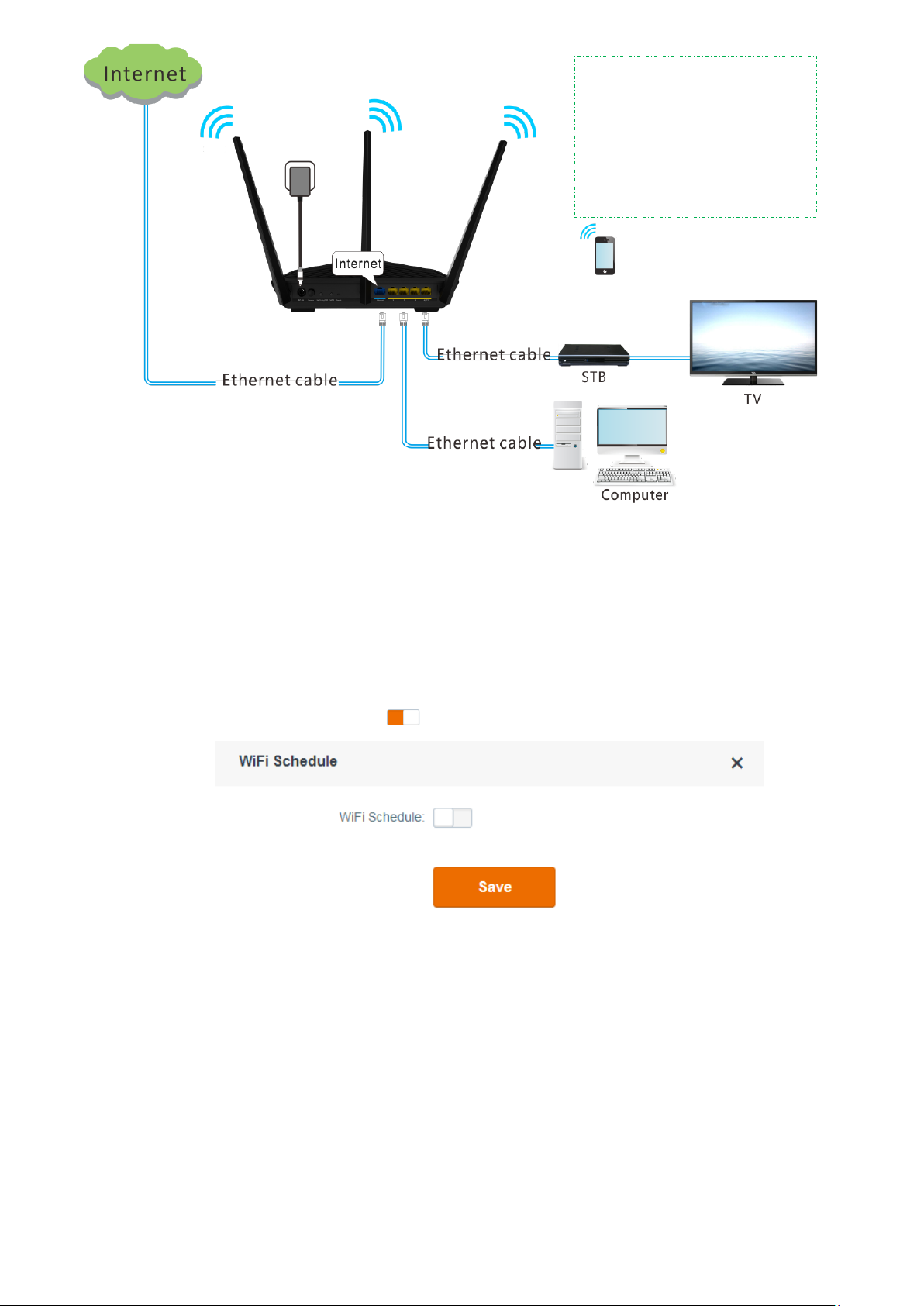
Step 1 Connect the Internet port using any of the methods shown in the following figure depending
on your internet connection means.
Step 2 Use the power adapter to connect the router to a power supply.
Step 3 Use a wireless device, such as a smart phone or tablet, to search for the WiFi network by the
WiFi name of the router and connect to the WiFi network. You can find the default WiFi name
and password on the label on the top of the router. For details about how to connect to the
WiFi network, refer to the appendix.
After the wireless device is connected to the router, log in to the router web UI on the wireless
device and configure an internet connection. For details, refer to Setting Up an Internet
Connection. After changing the WiFi name or password, you need to reconnect the wireless
device to the router.
- 6 -
Page 12

---End
2.1.2 Connecting to Your Router Using an Ethernet Cable
Perform the following procedure:
Step 1 Connect the Internet port using any of the methods shown in the following figure depending
on your internet connection means.
Step 2 Use the power adapter to connect the router to a power supply.
Step 3 Connect your computer to the 1, 2, 3, or 4/IPTV port of the router using an Ethernet cable.
After the computer is connected to the router, log in to the router web UI on the computer
and configure an internet connection. For details, refer to Setting Up an Internet Connection.
---End
2.2 Setting Up an Internet Connection
Step 1 Start a web browser, type tendawifi.com or 192.168.0.1 in the address bar, and press Enter
on the keyboard.
Step 2 Click Start.
The router detects your connection type.
- 7 -
Page 13

Step 3 According to the detection result, configure related settings. For details about the connection
type–specific configuration procedures, refer to Setting Up an Internet Connection with
PPPoE, Setting Up an Internet Connection with DHCP, and Setting Up an Internet Connection
with a Static IP Address.
- 8 -
Page 14

---End
2.2.1 Setting Up an Internet Connection with PPPoE
Step 1 Select PPPoE, enter your PPPoE user name and password, and click Next.
Step 2 Set a WiFi name and password, set a login password, and click Next.
Note
The WiFi password indicates the password for connecting to the WiFi network of the router. The login
password indicates the password for logging in to the router web UI. To use the same password for both
purposes, select Set up the login password to the same as the WiFi password on the Wireless Settings
page of the quick setup wizard. Ensure that your password meets the complexity requirement.
Step 3 When the login page appears, use the password you set to log in.
- 9 -
Page 15

Step 4 Go to the Internet Status page to view the current connection status.
If "Connected! You can surf the Internet." is displayed at Internet Settings, the internet is
accessible.
---End
2.2.2 Setting Up an Internet Connection with DHCP
Step 1 Select DHCP and click Next.
- 10 -
Page 16

Step 2 Enter a WiFi name, WiFi password, and login password, and click Next.
Note
The WiFi password indicates the password for connecting to the WiFi network of the router. The login
password indicates the password for logging in to the router web UI. To use the same password for both
purposes, select Set up the login password to the same as the WiFi password on the Wireless Settings
page of the quick setup wizard. Ensure that your password meets the complexity requirement.
Step 3 When the login page appears, use the password you set to log in.
- 11 -
Page 17

Step 4 Go to the Internet Status page to view the current connection status. If "Connected! You can
surf the Internet." is displayed at Internet Settings, the internet is accessible.
---End
2.2.3 Setting Up an Internet Connection with a Static IP Address
Step 1 Select Static IP, enter your static IP address and other related information, and click Next.
- 12 -
Page 18

Step 2 Set a WiFi name and password, set a login password, and click Next.
Note
The WiFi password indicates the password for connecting to the WiFi network of the router. The login
password indicates the password for logging in to the router web UI. To use the same password for both
purposes, select Set up the login password to the same as the WiFi password on the Wireless Settings
page of the quick setup wizard. Ensure that your password meets the complexity requirement.
Step 3 When the login page appears, use the password you set to log in.
- 13 -
Page 19

Step 4 Go to the Internet Status page to view the current connection status. If "Connected! You can
surf the Internet." is displayed at Internet Settings, the internet is accessible.
Note
If the internet is inaccessible after the preceding steps, refer to FAQ 5 in Appendix I.3.
For the detailed procedure for connecting to your router through WiFi, refer to Appendix 1.
If you change the WiFi password of the router when setting up an internet connection, all the
wireless connections of the router are disconnected. You can access the internet only after
reconnecting to the router using the new password.
---End
To enable the router to provide more stable WiFi signals and cover a wider area, position your
router as follows:
Put it on a high place at the center of your house.
Keep it close to your wireless devices, such as mobile phones and laptops.
Put it at a place with good ventilation. Unfold its antennas by 45°. Do not put it in an
enclosure, such as a wire distribution box, shoes cabinet, or metal box.
- 14 -
Page 20

Keep it away from electrical devices, such as ceiling fans and microwave ovens.
Keep it away from metal surfaces, such as metal doors or aluminum nails.
Keep it away from other materials that may affect your wireless signals, such as glass,
mirrors, and fish tanks.
- 15 -
Page 21

This chapter describes how to configure the functions of this router.
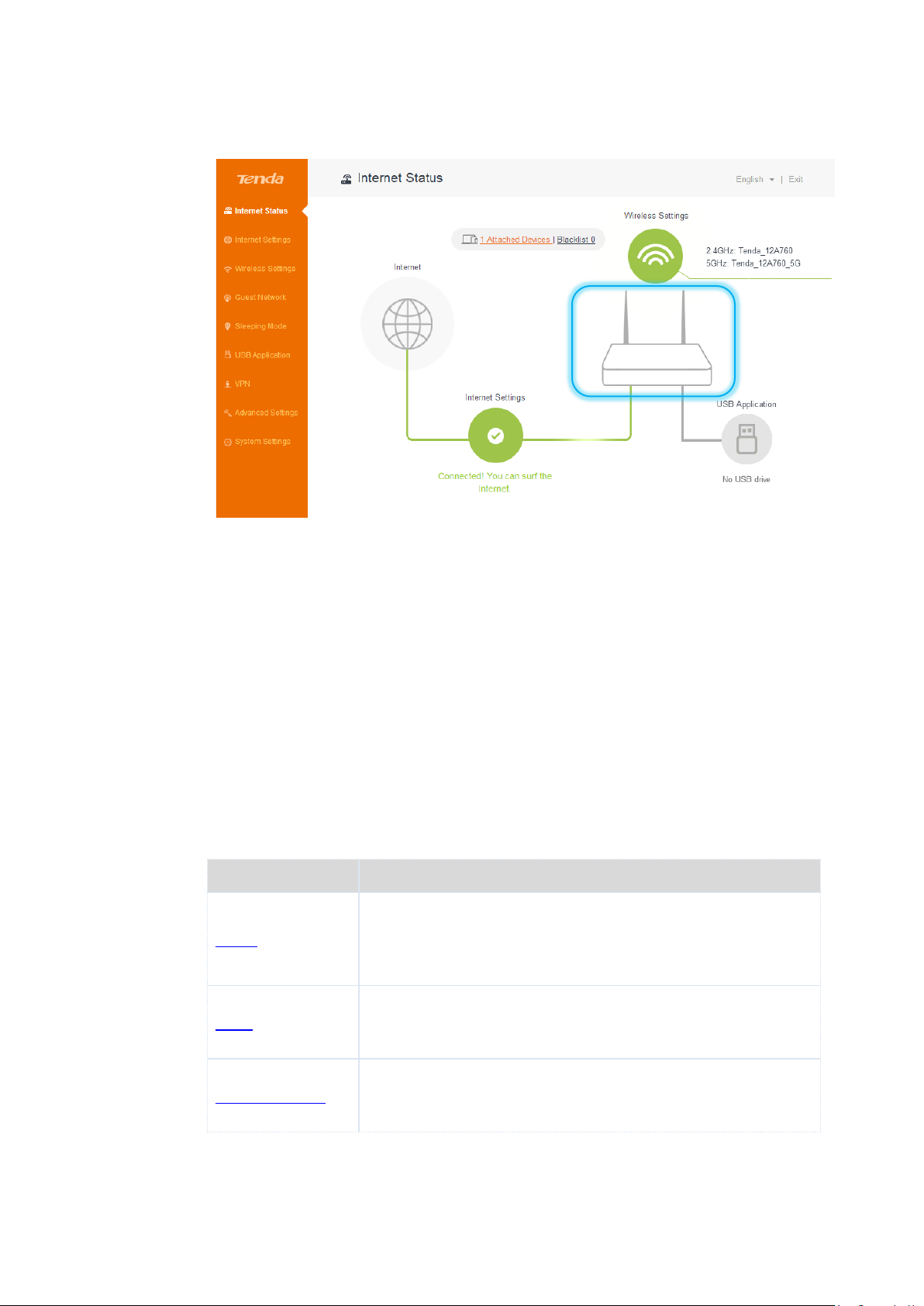
3.1 Internet Status
Log in to the router web UI and access the Internet Status page. On this page, you can view
the network status of the router, set basic WiFi information, add blacklisted devices, and so
on.
Chapter 3 Functions
3.1.1 Current Internet Connection Status
The current internet connection status and Internet Settings are displayed on the lower part
of the Internet Status page. If "Connected! You can surf the Internet." is displayed, you can
access the internet through the router. If another message is displayed, follow the onscreen
instruction to resolve the issue. You can click Internet Settings on this page and configure
internet settings.
- 16 -
Page 22

To configure the settings, select your connection type, set related parameters, and click Save.
For the detailed configuration procedure, refer to Internet Settings.
3.1.2 WiFi Settings and Information
You can click Wireless Settings in the upper-right corner of the Internet Status page to access
the Wireless Settings page.
- 17 -
Page 23

For the detailed configuration procedure, refer to WiFi Name & Password.
Note
Only the wireless devices that can work with 5 GHz signals can find and connect to the 5 GHz network of
the router. If your WiFi signals are not encrypted, you are recommended to encrypt those signals for
higher WiFi network security.
3.1.3 Online Device and Blacklist
The number of online devices and the number of blacklisted devices are displayed in the
upper-center part of the Internet Status page. See the following figure.
- 18 -
Page 24

To view the number of online devices of the router, click .
When detecting an unknown device, you can click Add to add it to the blacklist. A blacklisted
device can connect to the router but cannot access the internet through the router.
To view blacklisted devices, click .
To remove a device from the blacklist, click Remove corresponding to the device. The device
removed from the blacklist is added to the online devices list when it is online and can access
the internet through the router.
- 19 -
Page 25
Parameter
Description
PPPoE
If you directly connect an Ethernet cable with internet connectivity
to your computer, you can access the internet only after setting up
a dial-up connection on the computer using a user name and
password provided by your ISP.
DHCP
If you directly connect an Ethernet cable with internet connectivity
to your computer, you can access the internet without configuring
your computer.
Static IP Address
If you directly connect an Ethernet cable with internet connectivity
to your computer, you can access the internet only after setting
static IP address and other related information on your computer.
3.1.4 System Status
You can click the router icon on the Internet Status page to access the System Status page,
which shows the basic information, WAN port status, LAN port status, and WiFi status of the
router.
3.2 Internet Settings
This module enables you to configure internet settings and view internet connection status
and duration.
When you use the router for the first time or after you reset the router, the router detects
your internet connection type. You are recommended to select the detected type and follow
the instructions of the quick setup wizard to configure internet settings. If you do not
configure internet settings using the quick setup wizard, you can configure them on the
Internet Settings page.
The following table may help you understand your internet connection type. If you are still
uncertain about your internet connection type, consult your ISP.
- 20 -
Page 26

3.2.1 Setting Up an Internet Connection with PPPoE
Perform the following procedure:
Step 1 Set Select a connection type to PPPoE.
Step 2 Set User name and Password to the user name and password provided by your ISP.
Step 3 Click Save.
---End
If the "Connected! You can surf the Internet." message appears after a while, you can access
the internet through your router.
3.2.2 Setting Up an Internet Connection with DHCP
Perform the following procedure:
Step 1 Set Select a connection type to DHCP.
Step 2 Click Save.
---End
- 21 -
Page 27

If the "Connected! You can surf the Internet." message appears after a while, you can access
the internet through your router.
3.2.3 Setting Up an Internet Connection with a Static IP Address
Perform the following procedure:
Step 1 Set Select a connection type to Static IP.
Step 2 Set IP Address, Subnet Mask, Default Gateway, Preferred DNS Server, and Alternate DNS
Server to the static IP address and other related information provided by your ISP.
Step 3 Click Save.
---End
If the "Connected! You can surf the Internet." message appears after a while, you can access
the internet through your router.
3.3 Wireless Settings
This module enables you to configure the WiFi function of the router.
- 22 -
Page 28

Parameter
Description
2.4GHz and
5GHz
2.4GHz specifies whether to enable the router to provide 2.4 GHz WiFi
signals.
5GHz specifies whether to enable the router to provide 5 GHz WiFi
3.3.1 WiFi Name & Password
The router supports both 2.4 GHz and 5 GHz WiFi signals, featuring strong anti-interference
performance. This function enables you to configure WiFi names, encryption modes, and
passwords for both frequencies. The following figure shows a configuration example.
The following table describes the parameters.
- 23 -
Page 29

Parameter
Description
signals.
WiFi Name
It specifies the name of a WiFi network.
Security
Mode
It specifies the encryption modes supported by the router, including:
None: It indicates that a WiFi network is not encrypted and any clients
can access the network. This option is not recommended as it leads to
low network security.
WPA-PSK: It indicates that WPA-PSK/AES is adopted to authenticate
users.
WPA2-PSK: It indicates that WPA2-PSK/AES is adopted to authenticate
users.
WPA/WPA2-PSK: It indicates that WPA-PSK/AES and WPA2-PSK/AES
are adopted to authenticate users.
Password
It specifies the password required when a client access the WiFi network
of the router.
Hide
It specifies whether to prevent a WiFi name from being detected by
wireless devices. If this function is enabled, the corresponding WiFi name
is not broadcast. Therefore, the name is not displayed on the available
WiFi networks list of a wireless device. To connect a wireless device such
as a mobile phone to the WiFi network, you need to manually enter the
WiFi name and password of the network on the device.
3.3.2 WiFi Schedule
It specifies whether to enable the WiFi function schedule, which allows you to specify the
downtime of the function. By default, the schedule is disabled. For the configuration
procedure, refer to the following example.
Application Scenario
You want to disable the WiFi function during 23:00 to 7:00 every day for a healthier sleep
environment.
- 24 -
Page 30
WiFi function downtime:
23:00~07:00 every day
In this period, the WiFi function
of the router is inaccessible to
wireless devices.
Configuration
Step 1 Choose Wireless Settings > WiFi Schedule.
Step 2 Set WiFi Schedule to the state.
Ensure that the router is connected to the internet and the system time of the router is
synchronized with the local internet time.
The WiFi Schedule page appears.
Step 3 Set Turn off WiFi during to the downtime. In this example, the downtime is 23:00~07:00.
Step 4 Set Repeat to the days to which the downtime is applied. In this example, select Every Day.
Step 5 Click Save.
- 25 -
Page 31

---End
Verification
Verify that the WiFi network is inaccessible during 23:00 to 07:00 every day while accessible
during the rest of the time.
Note
To enable the WiFi function during the downtime, press the WiFi On/Off button on the back panel of the
router. This button is the preferred means to control the function. Alternatively, you can enable the WiFi
function by disabling the WiFi function schedule on the WiFi Schedule page.
3.3.3 Wireless Repeating
The wireless repeating function enables a wireless router or an AP to function as a wireless
repeater to extend wireless network coverage. At least two wireless routers are required for
implementing this function. You can use this router to extend wireless network coverage in
WISP or Client+AP mode.
Note
If wireless repeating is enabled, the Sleeping mode, IPTV function, guest network, WPS function, Tenda
App function, and WiFi function schedule become unavailable. For details, refer to the message on the
router web UI.
Application Scenario
User A subscribes to an 8 Mbps broadband service and purchases a wireless router for setting
up an LAN with internet connectivity in his 100 square meters apartment, which has three
bedrooms, one dining room, one living room, two restrooms, and one kitchen. The router is
placed in the living room. The WiFi signals are strong in the living room and master bedroom,
but too poor in the other bedrooms and the restrooms to access the internet.
- 26 -
Page 32

Solution
To improve internet connectivity, the user can add a Tenda AC18 router and configure the
wireless repeating function of the router to extend the WiFi network coverage. That will
eliminate blind areas in the apartment, enabling the user to access the internet anywhere in
the apartment.
The following figure shows the application scenario.
Assume that the router connections shown in the following figure are set up.
- 27 -
Page 33

Before configuring wireless repeating:
Ensure that the Internet port of the new router is not connected.
Ensure that the original router can access the internet.
Record the WiFi name and password of the original router, which are Tenda_2 and
12345678 in this example.
Enabling the WISP Mode
Log in to the web UI of the new router, choose Wireless Settings > Wireless Repeating and
configure the router and verify the configuration as follows:
Configuration
Step 1 Set Wireless Repeating to the state.
Step 2 Set Mode to WISP.
Step 3 Select the WiFi name of the original router from the Base Station WiFi Name drop-down list
box. In this example, select Tenda_2.
Step 4 Enter the WiFi password of the original router in the Base Station WiFi Password text box. In
this example, enter 12345678. (If the password is not set on the original router, leave this text
box blank.)
Step 5 Click Save.
Step 6 Click OK on the dialog box that appears.
The settings take effect after the router restarts.
---End
Verification
After the "Connected! You can surf the Internet." message appears on the Internet Status
page, access the internet through the WiFi network of the new router.
- 28 -
Page 34

Note
If the LAN IP address of the new router is in the same network segment as that of the original router,
an IP conflict occurs. In this case, the new router replaces its LAN IP address with another that
belongs to another network segment. You can log in to the web UI of the new router directly at
tendawifi.com.
If the upstream router enables the DHCP function, the new router obtains network connection
settings from the upstream router. If the upstream router disables the DHCP function, you need to
configure the connection settings manually.
In WISP mode, the new router can be connected wirelessly to a hotspot using DHCP or a static IP
address and access the internet through the hotspot.
Enabling the Client+AP Mode
Log in to the web UI of the new router, choose Wireless Settings > Wireless Repeating and
configure the router and verify the configuration as follows:
Configuration
Step 1 Set Wireless Repeating to the state.
Step 2 Set Mode to Universal Repeater.
Step 3 Select the WiFi name of the original router from the Base Station WiFi Name drop-down list
box. In this example, select Tenda_2.
Step 4 Enter the WiFi password of the original router in the Base Station WiFi Password text box. In
this example, enter 12345678. (If the password is not set on the original router, leave this text
box blank.)
Step 5 Click Save.
Step 6 Click OK on the dialog box that appears.
The settings take effect after the router restarts.
---End
Verification
Step 1 Log in to the web UI of the new router at tendawifi.com.
If login fails, check the web UI of the upstream router (original router) for the IP address
assigned to the new router, and log in to the web UI of the new router using this IP address.
- 29 -
Page 35

Parameter
Description
Network
Mode
It specifies a protocol adopted for wireless transmission. The default
setting is recommended. For 2.4 GHz networks, the 11b/g, 11b/g/n, and
11n protocols are available. For 5 GHz networks, the 11ac and 11a/n/ac are
available.
11b/g: It indicates that clients compliant with the 802.11b or 802.11g
protocol can connect to the router.
11b/g/n: It indicates that all clients working at 2.4 GHz and compliant
with the 802.11b, 802.11g, or 802.11n protocol can connect to the
router.
11n: It indicates that clients working at 2.4 GHz and compliant with
802.11n can connect to the router.
11ac: It indicates that clients complaint with the 802.11ac protocol can
Step 2 Choose Internet Status and view the connection status.
If the "Bridged successfully in Universal Repeater mode." message appears, you can access the
internet through the new router.
---End
3.3.4 Channel & Bandwidth
It is recommended that you retain the default channel and bandwidth settings. Change the
settings only when necessary.
The following table describes the parameters.
- 30 -
Page 36

Parameter
Description
connect to the router.
11a/n/ac: It indicates that clients working at 5 GHz and compliant with
the 802.11a, 802.11n or 802.11ac protocol can connect to the router.
Channel
It specifies the operating channel of a WiFi network. You retain the default
setting, or change it as required. A channel different from nearby channels
are recommended for less interference and better wireless transmission
efficiency. You can use a third-party tool to identify the channels different
from nearby channels.
Bandwidth
It specifies the bandwidth of the operating channel of a WiFi network.
Change the default setting only when necessary.
20: It indicates that the channel bandwidth of a router is 20 MHz.
40: It indicates that the channel bandwidth of a router is 40 MHz.
20/40: It specifies that a router can switch its channel bandwidth
between 20 MHz and 40 MHz based on the ambient environment. This
option is available only to a router working at 2.4 GHz.
80: It indicates that the channel bandwidth of a router is 80 MHz. This
option is available only to a router working at 5 GHz.
20/40/80: It specifies that a router can switch its channel bandwidth
among 20 MHz, 40 MHz, and 80 MHz based on the ambient
environment. This option is available only to a router working at 5 GHz.
3.3.5 Transmit Power
You can switch the signal strengths of the 2.4 GHz and 5 GHz operating frequencies of the
router. By default, the signal strengths are set to High. You can set the signal strengths to Low,
Medium, or High as required.
If wireless connections work properly with low signal strength, use the Low option.
If you need wider coverage, use the Medium or High option to boost WiFi signals.
To set the signal strength, choose Wireless Settings > Transmit Power, select options as
required, and click Save.
- 31 -
Page 37

3.3.6 WPS
The WPS function enables wireless devices to quickly connect to encrypted WiFi networks of
the router. To connect a wireless device to the router using the WPS function, follow the
onscreen instruction in the WPS dialog box.
3.3.7 Beamforming
The router can implement the Beamforming technology to boost WiFi signals, which not only
enables faster wireless transmission, but also further stabilizes wireless connections between
the router and wireless devices. By default, explicit beamforming is enabled. It is
recommended that you retain the default setting.
3.4 Guest Network
A guest network is a network dedicated to guests. Clients connected to a guest network can
access the internet and communicate with each other, but cannot access the router web UI or
the non-guest network. This enables guests to access the internet and meanwhile ensures
security of the non-guest network.
You can set a WiFi name for the 2.4 GHz network and 5 GHz network each. These networks
share the same password. To distinguish between the non-guest WiFi networks of the router
and the guest WiFI networks of the router, do not adopt the same name for the networks.
- 32 -
Page 38

3.5 Sleeping Mode
The Sleeping mode enables the router to reduce power consumption. By default, this function
is disabled. After it is enabled, the indicators and WiFi function of the router enter the
Sleeping mode.
If the The Sleeping Mode start time will delay when data is still transmitted. option is
selected and no client exchanges data with the router within three minutes, the router enters
the Sleeping mode. If the The Sleeping Mode start time will delay when data is still
transmitted. option is selected, a client exchanges data with the router, but the traffic is less
than 3 KB/s, the router enters the Sleeping mode after 30 minutes.
Note
The Sleeping mode works based on time settings. If the system time is not synchronized with the
internet time, the Sleeping mode cannot work properly.
- 33 -
Page 39

When the router is in Sleeping mode, you can enable the WiFi function by pressing the WiFi
On/Off button on the rear panel of the router or using Tenda App. For details about how to
enable the WiFi function using Tenda App, refer to the Tenda App usage.
3.6 USB Application
3.6.1 Sharing Files
The router can automatically recognize a USB storage device connected to the USB port of the
router and display the space usage of the device on the Internet Status page. The device can
be accessed over the LAN and internet.
To configure the USB storage device settings, choose USB Application > File Share.
- 34 -
Page 40

Parameter
Description
Basic
parameters
sda
It specifies the space usage of a USB storage device
connected to the router.
It allows you to eject a connected USB storage device
before removing it from the router. This helps prevent
data loss.
FTP Server
It specifies the address for clients of the router to access
the USB storage device. The default address is
ftp://192.168.0.1:21. You can click this link to access the
device.
Samba Server for Windows
It specifies the address for Windows clients of the router
to access the USB storage device. The default address is
\\192.168.0.1.
Samba Server for MAC
It specifies the address for MAC clients of the router to
access the USB storage device. The default address is
smb://192.168.0.1.
Allow Internet Visits
It specifies whether to allow or disallow internet users to
access the USB storage device. By default, internet users
cannot access the device.
Access from Internet
It indicates the address for internet users to access a USB
storage device. The address is effective only after Allow
Internet Visits is enabled.
If a USB storage device is connected to the router, the router displays information about the
device on the dialog box. See the following figure.
The following table describes the parameters.
- 35 -
Page 41

Parameter
Description
Account
management
parameters
User name and Password
User name and Password specify the user name and
password that must be entered when a user accesses a
USB storage device connected to the router. You can
change the user name and password as required.
Permission
Read/Write: It indicates that a user can access and
modify the resources in a USB storage device.
Read: It indicates that a user can only access the
resources in a USB storage device.
It allows you to add a user account.
Accessing the USB Storage Device Connected to the Router over the LAN
An AC18 router is used to set up a LAN in an apartment. A USB storage device is connected to
the USB port of the router and functions as a file server. Users can download resource from
the server. Assume that:
The server address is \\192.168.0.1.
The server user name and password are admin.
To access the USB storage device, perform the following procedure: (Windows 7 is used as an
example for description.)
Step 1 Click and enter \\192.168.0.1.
Step 2 Press Enter.
Step 3 Enter your user name and password, which are admin in this example, and click OK.
- 36 -
Page 42

Step 4 Double-click the sda folder.
If the folder is accessible, the resources in the USB storage device are displayed.
- 37 -
Page 43

---End
Accessing a USB Storage Device Connected to the Router over the Internet
Application Scenario
An AC18 router is used to set up a LAN in an apartment. A USB storage device is connected to
the USB port of the router and functions as an FTP server. Allow Internet Visits is enabled to
make the USB storage device accessible over the internet. Assume that:
− The server address for internet users is ftp://172.16.200.115:21.
− The server user name and password are admin.
Note
In this example, the server address for internet users is only for reference. Ensure that the server address
is a public IP address.
Configuration
Step 1 Enable Allow Internet Visits.
Choose USB Application > File Share and set Allow Internet Visits to the state.
- 38 -
Page 44

Step 2 Access the USB storage device over the internet. (Windows 10 is used as an example to
describe the procedure.)
1. Double-click This PC.
2. Enter the server address, which is ftp://172.16.200.115:21 in this example in the address
bar of the window that appears, and press Enter.
- 39 -
Page 45

3. Enter your user name and password, which are admin in this example, and click Log On.
A dialog box appears.
4. Double-click the sda folder.
If the folder is accessible, the resources in the USB storage device are displayed.
- 40 -
Page 46

3.6.2 Sharing Multimedia Resources Using DLNA
DLNA is a solution to share multimedia resources among digital devices by wired or wireless
means. For example, you can use the mobile phone and the DLNA controller to enable your TV
or computer to play the video and audio clips and display the images in your portable disk.
This router supports the DLNA function, which enables clients to access resources in the
server through wired or wireless connections to the router. The following figure shows the
common application scenario of this function.
By default, this function is disabled. To ensure it, perform the following procedure:
Step 1 Choose USB Application > DLNA.
- 41 -
Page 47

Step 2 Set DLNA Service to the state. See the following figure.
---End
Application Scenario
User A uses an AC18 wireless router to set up a LAN in his apartment. His desktop PC, smart
phone, and tablet access the internet through the router. He connects a USB storage device to
the USB port of the router and stores lots of movies, TV series, images, and audio clips in the
device.
The following figure shows the application scenario.
- 42 -
Page 48

Sharing videos, audios, and images: (A computer running Windows 7 is taken as an example to
describe the procedure.)
Step 1 Enable the media streaming function.
1. Click Start in the lower-left corner of the desktop and choose Control Panel.
2. Click Network and Internet.
- 43 -
Page 49

3. Click Network and Sharing Center.
4. Click Change advanced sharing settings.
- 44 -
Page 50

5. Click Choose media streaming options….
6. Click Turn on media streaming.
- 45 -
Page 51

7. Click Windows services administrative tool.
8. Set Startup Type of SSDP Discovery, UPnP Device Host, and Windows Media Player
Network Sharing Service to Automatic.
- 46 -
Page 52

9. Go to the Advanced sharing settings page and click Choose media streaming options….
- 47 -
Page 53

This field allows you to set the name of your media library.
phones, and TVs that attempt to access the media library.)
The Media streaming options page appears, showing that the media streaming function is
enabled.
(The name is displayed on remote computers, mobile
Windows detects the devices that support media steam playback on
the LAN and allows you to decide whether to allow the devices to
access your media library. (By default, all the devices can access the
media library.) After the configuration, click OK.
Windows Media Player of a Windows OS can access the devices where DLNA is enabled and
function as a platform for playing the media resources of the devices locally.
Run Windows Media Player, click Stream, and select the Allow remote control of my Player
and Automatically allow devices to play my media menu items. If a confirmation dialog box
- 48 -
Page 54

appears when you select the menu items, follow the onscreen instruction to confirm the
operation.
Step 2 Enable the DLNA function of the router.
Choose USB Application > DLNA and set DLNA Service to the state. See the following
figure.
Step 3 On the computer, browse the video, audio, and image files in the USB storage device
connected to the router.
1. Run Windows Media Player.
The router is displayed in the Other Libraries of the left pane.
2. Click the router.
The video, audio, and image files in the USB storage device appear.
- 49 -
Page 55

---End
3.6.3 Printer Service
This router allows you to share a printer connected to the USB port of the router among all
the computers on your LAN.
By default, this function is disabled. To enable it, perform the following procedure:
Step 1 Choose USB Application > Printer Service.
Step 2 Set Printer Service to the state.
The following figure shows the topology.
- 50 -
Page 56

---End
Installing a Printer
Step 1 Connect the printer to the USB port of the router.
Step 2 Enable the printing service of the router.
Note
HP LaserJet 1020 is taken as an example to describe the procedure.
Step 3 Install Tenda's printing service control program on your computer. (A computer running
Windows 7 is taken as an example to describe the procedure.)
1. Download the package of the program from http://www.tendacn.com and decompress
the package.
- 51 -
Page 57

2. Double-click .
The dialog box shown in the following figure appears.
3. Click OK.
4. Wait until installation preparation is complete.
5. Click Next.
A dialog box appears.
- 52 -
Page 58

6. Enter your user name and organization name and click Next.
7. Click Change… and change the installation path if necessary. Then, click Next.
8. Click Install.
- 53 -
Page 59

9. Click Finish.
- 54 -
Page 60

Installation is complete and a printer shortcut icon appears on the desktop of the
computer.
10. Wait a moment for the program to detect the printer connected to the router.
11. Select the printer and choose Auto-Connect Printer > Set Auto-Connect Printer.
- 55 -
Page 61

Note
If you click Connect after selecting the printer, the printer cannot be shared among multiple computers.
In this case, another computer can use the printer only after this computer is disconnected from the
printer. Therefore, if multiple computers need to use the printer at the same time, you are
recommended to choose Auto-Connect Printer > Set Auto-Connect Printer to share the printer.
12. Select the printer and click Apply.
Step 4 Install the driver of the printer on the computers on your LAN.
1. Obtain the driver from the package of your printer or download the driver from the
official website of the manufacturer of the printer.
2. Double-click .
The dialog box shown in the following figure appears.
- 56 -
Page 62

3. Click Run.
4. Wait until file extraction is complete. See the following figure.
5. Click Install.
6. Click Next.
7. Wait until installation is complete.
- 57 -
Page 63

Parameter
Description
PPTP Server
It specifies whether to enable the PPTP server function. If the function is
enabled, the router functions as a PPTP server.
Address Pool
It specifies the range of IP addresses that the server can assign to clients.
MPPE
Encryption
It specifies the algorithm used to encrypt PPP data. 40-bit encryption and
128-bit encryption are supported. Ensure that the server and clients
adopt the same encryption mode.
8. Click Finish.
After installation is complete, the printer prints a test page.
---End
3.7 VPN
A VPN is a logical private network set up over a public network (usually the internet) without
physical lines. The VPN technology allows employees at a branch of an enterprise and
employees at the headquarters to exchange resources without exposing these resources to
other internet users.
This router can function as a PPTP server or a PPTP/L2TP client. The following section
describes how to configure the router as a PPTP server or a PPTP/L2TP client.
3.7.1 PPTP Server
Functioning as a PPTP server, the router receives virtual connection requests from clients over
the internet and sets up virtual connections for communication through the connections.
To configure the router as a PPTP server, choose VPN > PPTP Server, set PPTP Server to the
state, and set the parameters. By default, the PPTP server function is disabled. The
following figure shows the dialog box that appears after the function is enabled.
The following table describes the parameters.
- 58 -
Page 64

Parameter
Description
Status
It specifies the status of a connection.
User name
It specifies the user name assigned by the PPTP server to a client.
Password
It specifies the password assigned by the PPTP server to a client.
Action
It allows you to add or delete user accounts.
Example
Computer 1 is connected to AC18 and assigned the IP address 192.168.0.104. The computer
has been configured as an FTP server (port number 21) to store resources. Computer 2 needs
to access the resources over the internet. You can address this requirement using the VPN
function.
The WAN IP address of the router is
113.88.112.220, which is the PPTP
server IP address.
Configuration
Step 1 Configure the PPTP server on the router.
1. Choose VPN > PPTP Server. The PPTP Server dialog box appears.
2. Set PPTP Server to the state to enable the server.
3. Set Address Pool to the range of IP addresses that the PPTP server assigns to clients for
VPN communication. This range cannot overlap the LAN or WAN IP address range of the
router.
4. Set MPPE Encryption and MPPE Encryption Bits according to your specific requirements.
5. Set User name and Password to your user name and password for clients to connect to
the PPTP server, and click Add.
6. Click Save.
- 59 -
Page 65

Step 2 Connect computer 2 to the PPTP server using a VPN dial-up connection.
Note
Windows 7 is taken as an example to describe the procedure.
1. Click and then Open Network and Sharing Center.
2. Click Set up a new connection or network.
- 60 -
Page 66

3. Click Connect to a workplace and then Next.
4. Click Use my Internet connection (VPN). If a dialog box appears, following the onscreen
instruction to perform operations.
- 61 -
Page 67

5. Enter the IP address of the PPTP server in the Internet address text box. Click Next.
6. Enter the user name and password for connecting to the PPTP server, such as admin.
Click Create. The VPN connection dialog box appears.
- 62 -
Page 68

7. Click Connect Now.
- 63 -
Page 69

On the network connection list of the computer, the VPN connection is in Connected state.
Remote Access
---End
Access the resources on computer 1 from computer 2 using a URL in the following format: ftp:
//Server IP address:Service port number. In this example, the URL is ftp: //192.168.0.104:21.
- 64 -
Page 70

3.7.2 PPTP/L2TP Client
You can configure the router as a PPTP/L2TP client for accessing resources on its server.
To configure the router as a PPTP/L2TP client, choose VPN > PPTP/L2TP Client, set PPTP/L2TP
Client to the state, and set the parameters. By default, the PPTP/L2TP client function is
disabled. The following figure shows the dialog box that appears after the function is enabled.
- 65 -
Page 71

Parameter
Description
PPTP/L2TP Client
It specifies whether to enable the PPTP/L2TP client function. If
the function is enabled, the router functions as a PPTP/L2TP
client.
Client Type
It specifies whether the router is a PPTP client or an L2TP client.
MPPE Encryption
It specifies the algorithm used to encrypt PPP data. 40-bit
encryption and 128-bit encryption are supported. Ensure that the
server and clients adopt the same encryption mode.
Server IP/Domain
Name
It specifies the IP address or domain name of the VPN server to
which the router is to be connected.
User name
It specifies the user name assigned by the PPTP server to the
router.
Password
It specifies the password assigned by the PPTP server to the
router.
Status
It specifies the status of a connection.
User name and password: 123
The following table describes the parameters.
Example
Server IP address: 1.1.1.1
Domain name: XXXX
Encryption mode: MPPE
Encryption bits: 128
You have subscribed to a PPTP-based VPN service from an ISP. The ISP notifies you of the
server IP address or domain name, your user name and password, and the encryption mode.
(The parameters used in this example are only for reference.) You can access the resources
provided by the ISP using a PPTP client.
- 66 -
Page 72

Configuration
Step 1 Log in to the router web UI, choose VPN > PPTP/L2TP Client.
Step 2 Set PPTP/L2TP Client to the state.
Step 3 Set Client Type based on the type of service that you subscribe. In this example, set it to
Step 4 Set MPPE Encryption and MPPE Encryption Bits based on the service that you subscribe. In
Step 5 Set Server IP/Domain Name, User name, and Password based on the information provided
Step 6 Click Connect.
Remote Access
PPTP.
this example, set MPPE Encryption to the state and MPPE Encryption Bits to 128.
by the ISP.
---End
You can access the resources on the ISP's VPN server through the router.
3.8 Advanced Settings
The router provides advanced settings to address tailored requirements.
- 67 -
Page 73

Parameter
Description
Device Name
It specifies the name of a device.
IP Address
It specifies the IP address assigned to a device.
MAC Address
It specifies the MAC address of a device.
3.8.1 Parental Control
This function enables you to control internet connectivity availability and content accessibility
for devices connected to the router, ensuring healthy internet usage.
To implement parental control, perform the following procedure:
Step 1 Choose Advanced Setting> Parental Control.
All the devices connected to the router are listed.
Step 2 Click corresponding to the device to which parental control must be applied, and set
the parameters to specify the time when the internet is accessible to the device and the
websites accessible to the device.
The following table describes the parameters.
- 68 -
Page 74

Parameter
Description
Action
It allows you to set parental control rules for a device.
It allows you to manually add devices and rules.
Application Scenario
You have an 8 Mbps broadband connection at your apartment and have purchased a wireless
router for setting up a network in your apartment. Your kids often watch videos over the
internet at home. In Monday to Friday, you want to allow them to access video websites such
as YouTube only during 20:00 to 22:00.
Configuration
Step 1 Choose Advanced Settings > Parental Control, and click corresponding to a device to
which parental control must be applied.
Step 2 (Optional) Click Edit and change the device name so that it is easily recognized.
Step 3 Set Internet Accessible Time to the period when the device is allowed to access video
websites.
Step 4 Set Repeat to the days when you want to apply the control.
Step 5 Set Website Limit to the state to enable the control. By default, it is enabled.
Step 6 Set Access Control to Blacklist.
Blacklist: It indicates that the device cannot access the specified websites.
White List: It indicates that the device can access only the specified websites.
Step 7 Set Forbidden Websites to youtube.
Step 8 Click Save.
- 69 -
Page 75

---End
The entry shown in the following figure appears.
Cancelling Parental Control
Click the icon corresponding to the device for which you want to cancel the control.
It changes to .
3.8.2 Bandwidth Control
If multiple devices access the internet through the router, bandwidth control is recommended,
so that high-speed file download by a device does not reduce the internet access speed of the
other devices.
- 70 -
Page 76

Parameter
Description
Device Name
It specifies the name of a device.
Device Info
It specifies the MAC address and IP address of a device.
Current Speed
It specifies the current upload and download speeds of a device.
Upload Limit and
Download Limit
Upload Limit specifies the maximum upload speed at Mbps of a
device.
Download Limit specifies the maximum download speed at
Mbps of a device.
Action
It allows you to manually add devices and rules.
To implement bandwidth control, choose Advanced Settings > Bandwidth Control. By default,
this function is disabled. The following figure shows the dialog box that appears after this
function is enabled.
The following table describes the parameters.
Application Scenario
You have an 8 Mbps broadband connection at your apartment. Multiple devices sharing the
connection often compete for bandwidth. To ensure that every device can access the internet
properly, you want to specify the maximum bandwidth for every device. For example, you
want to limit the download speed of every device to 2 Mbps. The following figure shows the
application scenario.
- 71 -
Page 77

Configuration
Step 1 Choose Advanced Settings > Bandwidth Control and set Bandwidth Control to the
Step 2 Select 2Mbps from the Download Limit drop-down list box corresponding to each device.
Step 3 Click Save.
state.
- 72 -
Page 78

.Verification
---End
Verify that the download speed of each device does not exceed 2 Mbps.
3.8.3 Tenda App
After enabling the Tenda App function of this router, you can use Tenda App to remotely
manage the router.
To use Tenda App to remotely manage the router, perform the following procedure:
Step 1 Install Tenda App.
Use you smart device (smart phone or tablet) to scan the QR code on the Advanced Settings >
Tenda App page to download, and install the app on your smart device.
- 73 -
Page 79

Note
Your smart device must be connected to the internet so that it can download the app. (Use an app with
the scanning function to scan the QR code.)
Step 2 Register an account.
After installing Tenda App, register an account using your mobile number or email address.
Use the account to log in to Tenda App.
This account allows you to connect to Tenda's cloud server for remotely managing the router.
- 74 -
Page 80

Step 3 Attach the router to your account.
On the UI of Tenda App, tap Add and enter the login password of the router to attach the
router to the account.
After the router is attached to your account, the router appears on the router list each time
you log in with your account, regardless of whether the router is online.
Note
If the router is in offline state, you cannot manage it using Tenda App.
- 75 -
Page 81

Note
When attaching the router to your account, ensure that your smart device is connected to the WiFi
network of the router and the router can access the internet.
Step 4 Enable the Tenda App function.
1. Go to the Tenda App page of the router and set Tenda App to the state.
The router accesses the cloud server and detects your account. (If it fails to detect your
account, enter your account information manually.)
2. Click Save.
You can now use Tenda App to manage the router.
---End
3.8.4 LED Control
The following figure shows the available LED indicator control modes. Select one of the modes
as required and click Save.
- 76 -
Page 82

Parameter
Description
LED ON
It indicates that all the LED indicators are in ordinary states.
LED OFF
It indicates that the PWR indicator blinks slowly and the other
indicators are turned off.
LED Schedule
It indicates that all the LED indicators are turned off in specified periods
and return to their ordinary states when the periods expire.
Parameter
Description
DDNS
It specifies whether to enable the DDNS function.
The following table describes the parameters.
3.8.5 DDNS
DDNS maps the WAN IP address (public IP address) of the router to a domain name for
dynamic domain name resolution. This ensure proper operation of functions that involve the
WAN IP address of the router, such as the remote management and virtual server functions.
To enable the DDNS function, choose Advanced Settings > DDNS. By default, it is disabled. the
following figure shows the dialog box that appears when the function is enabled.
The following table describes the parameters.
- 77 -
Page 83

Parameter
Description
Service
Provider
It specifies a DDNS service provider. The supported service providers
include no-ip.com, 3322.org, dyndns.org, 88ip.cn, and oray.com.
User name
It specifies the user name registered on a DDNS service provider's
website for logging in to the DDNS service.
Password
It specifies the password registered on a DDNS service provider's website
for logging in to the DDNS service.
Domain
Name
It specifies the DDNS domain name register on a DDNS service provider's
website.
Connection
Status
It indicates the current status of the DDNS service.
WAN IP address of the router:
218.88.93.33
Application Scenario
An AC18 is used to set up a network at an apartment and must be managed remotely using a
web browser. This requirement can be addressed by combining the remote management and
DDNS functions. Assume that the registered domain name is tenda.dyndns.org, the user
name is Tenda, and the password is 1234578.
The following figure shows the application scenario.
102.33.66.88
IP address of computer 2:
Configuration
Step 1 Enable the DDNS function.
1. Set DDNS to the state.
2. Set Service Provider to dyndns.org.
If you do not have a DDNS account, select a service provider and click to go to the
service provider's website. Register a DDNS account and memorize your user name, password,
and domain name of the account.
3. Set User name to your user name for logging in to your DDNS service, which is Tenda in
this example.
- 78 -
Page 84

4. Set Password to the password for logging in to your DDNS service, which is 12345678 in
this example.
5. Set Domain Name to the domain name registered on the website of your DDNS service
provider, which is tenda.dyndns.org in this example.
6. Click Save.
7. Wait until the connection status changes to Connected.
Step 2 Configure the remote management function.
1. Choose Advanced Settings > Remote Management.
2. Set Remote Management to the state.
3. Set Remote IP Address to the WAN IP address (public IP address) of the computer where
remote management is to be performed. In this example, set it to the WAN IP address of
computer 2, which is 218.88.93.33.
- 79 -
Page 85

4. Set Port to the port number of the web service, which is generally 8080. You can also
select a port number from the 1024~65535 range but the port number must not be the
same as that of the virtual server.
5. Click Save.
Step 3 Access the web UI of AC18 on computer 2.
On computer 2, enter http://102.33.66.88:8080 or http://tenda.dyndns.org:8080 in the
address bar of a web browser.
---End
3.8.6 Virtual Server
If computers are connected to the router to form a LAN and access the internet through the
router, internet users cannot access the hosts on the LAN. Therefore, the servers, such as web
servers, email servers, and FTP servers, on the LAN are inaccessible to internet users. To
enable internet users to access a LAN server, enable the virtual server function of the router,
and map one service port of the virtual server to the IP address of the LAN server. This
enables the router to forward the requests arriving at the port from the internet to the LAN
server.
To configure the virtual server function, choose Advanced Settings > Virtual Server. By default,
the function is disabled.
The following table describes the parameters.
- 80 -
Page 86

Parameter
Description
Internal IP
It specifies the IP address of a server that resides on the LAN of the
router.
Internal Port
It specifies the service port number of a server that resides on the LAN of
the router.
External Port
It specifies a router port accessible to internet users.
Protocol
It specifies the protocol of a service provided through the router for
internet users. If you are uncertain about which service protocol is used,
TCP/UDP is recommended.
Action
It allows you to manually add LAN servers and rules.
Application Scenario
An AC18 is used to set up a LAN and a web server on the LAN must be accessible to internet
users. This requirement can be addressed using the virtual server function. The following
figure shows the application scenario.
WAN IP address of the router:
102.33.66.88
IP address of the web server:
Prerequisites
The WAN port of the router is assigned a public IP address.
Computer 1 is assigned a static IP address. The default gateway IP address is the LAN IP
address of the router.
All the firewall and antivirus software that may deny internet users' access to LAN servers
is disabled when virtual server function is used.
Configuration
Step 1 Choose Advanced Settings > Virtual Server.
Step 2 Set Internal IP to the IP address of a LAN server. In this example, enter the IP address of
computer 1, which is a web server.
Step 3 Set Internal Port to the port number of the web service, which is 80 in this example.
External Port is set automatically.
- 81 -
Page 87

Step 4 Set Protocol to the protocol of the web service. TCP/UDP is recommended.
Step 5 Click Add and then Save.
Remote Access
3.8.7 DMZ
---End
Enter Protocol name://WAN port IP address:External port in the address bar of a web browser
on a computer over the internet to access the resources on the LAN server. In this example,
enter http://102.33.66.88:80.
Note
If you are uncertain about the WAN IP address of the router, you can use both the virtual server and
DDNS functions to allow internet users to access the LAN server using a domain name.
A DMZ host on a LAN can communicate with the internet without limit. You can set a
computer that require higher internet connection throughput, such as a computer used for
video conferencing or online gaming, as a DMZ host for better user experience.
- 82 -
Page 88

Note
A DMZ host is not protected by the firewall of the router. A hacker may leverage the DMZ host to
attack your LAN. Therefore, enable the DMZ function only when necessary.
Manually set the IP address of the LAN computer that functions as a DMZ host, to prevent IP address
changes, which lead to DMZ function failures.
Security software, antivirus software, and the built-in OS firewall of the computer may cause DMZ
function failures. Disable them when using the DMZ function. If the DMZ function is not required, it
is recommended that you disable it and enable your firewall, security, and antivirus software.
To configure the DMZ function, perform the following procedure:
Step 1 Choose Advanced Settings > DMZ.
Step 2 Set DMZ to the state.
Step 3 Set DMZ Host IP to the IP address of the DMZ host.
Step 4 Click Save.
---End
3.8.8 Remote Management
This function enables you to remotely log in to the web UI of the router over the internet.
To configure the function, choose Advanced Settings > Remote Management. By default, the
function is disabled. The following figure shows the dialog box that appears after the function
is enabled.
- 83 -
Page 89

218.88.93.33
Application Scenario
An AC18 is used to set up a LAN at an apartment and the router must be logged in and
managed over the internet. Assume the public IP address of the router is 102.33.66.88 and
the public IP address of the computer for remotely login is 218.88.93.33.
The following figure shows the application scenario.
WAN IP address of the router:
102.33.66.88
Configuration
IP address of computer 2:
Note
The computer used to remotely log in to the router web UI must be assigned a public IP address. If it is
assigned a private IP address, use the public IP address of the router to which the computer connects for
remote login. Private IP addresses are not applicable to remote management.
Step 1 Choose Advanced Settings > Remote Management.
- 84 -
Page 90

Step 2 Set Remote Management to the state.
Step 3 Set Remote IP Address to the WAN IP address (public IP address) of the computer where
remote management is to be performed. In this example, set it to the WAN IP address of
computer 2, which is 218.88.93.33. If you are uncertain about the IP address of the computer,
set this parameter to 0.0.0.0 (default value). In this case, all computers can log in to the
router web UI over the internet.
Step 4 Set Port to the port number of the web service, which is generally 8080. You can also select a
port number from the 1024~65535 range but the port number must not be the same as that
of the virtual server.
Step 5 Click Save.
Remote Access
3.8.9 IPTV
---End
Enter http://102.33.66.88:8080 in the address bar of computer 2 and log in to the router web
UI to perform remote management.
Note
The public IP address of the router may change. Therefore, you need to confirm the IP address each time
you want to remotely log in to the router web UI, which is troublesome. To address this issue, you can
use the DDNS function to bind the public IP address with a fixed domain name, so that you can use the
domain name to log in to the router web UI. To implement this measure, configure the DDNS function
and then the remote management function of the router.
This router supports the multicast and STB functions. To configure the functions, choose
Advanced Settings > IPTV. By default, the functions are disabled.
- 85 -
Page 91

Multicast
This function enables you to access multicast resources over the internet. If you want to watch
live videos, it is recommended that you enable this function.
Step 1 Set Multicast to the state.
STB
Step 2 Click Save.
---End
If you connect an STB to the router and subscribe to an IPTV service, enable the STB function.
- 86 -
Page 92

Step 1 Set Set-top Box to the state.
Step 2 Set Select a zone to the VLAN of your IPTV service. If the service has no VLAN ID, select No
VLAN ID. Otherwise, select Custom and enter the VLAN ID of the service. Shanghai indicates
the IPTV service VLAN in Shanghai.
Step 3 Click Save.
Step 4 Connect the STB to the 4/IPTV port of the router. The connected port functions only as an
IPTV port.
---End
You can then watch IPTV programs on a smart TV connected to your router.
3.8.10 Firewall
The firewall is used to protect the router against some attacks, helping ensure network
security. By default, the firewall of the router is enabled. It is recommended that you retain
the default setting.
Note
After configuring the router, you may need to configure your STB as well. For details, refer to the user
guide for your STB or TV.
- 87 -
Page 93

3.8.11 Static Routing
Routing is performed to select the best route for delivering data from a source address to a
destination address. A static route is a manually configured route, which is simple, efficient,
and reliable. Appropriate static routes help reduce the number of route selection problems
and reduce route selection load, increasing the packet forwarding speed.
To configure static routes, choose Advanced Settings > Static Routing.
The following table describes the parameters.
- 88 -
Page 94

Parameter
Description
Target
Network
It specifies the IP address of a packet destination.
Subnet Mask
It specifies the subnet mask of the IP address of a packet destination.
Gateway
It specifies the IP address of the next hop of packets transmitted from
the router.
Interface
It specifies the WAN port of the router for transmitting packets.
Action
It allows you to add a static route.
Application Scenario
See the following figure. You want to access the internet and the LAN server at the same time.
Nevertheless, the default gateway of AC18 is the LAN IP address of router 1 (which is
192.168.1.1), making the LAN server inaccessible. In this case, you can configure a static route
on AC18 to enable your computer to access the LAN server.
Configuration
Step 1 Choose Advanced Settings > Static Routing.
- 89 -
Page 95

Step 2 Set Target Network to the network segment where the LAN server resides, which is
172.16.0.0 in this example.
Step 3 Set Subnet Mask to the subnet mask of the network segment, which is 255.255.0.0 in this
example.
Step 4 Set Gateway to the LAN IP address of router 2, which is 192.168.1.10 in this example.
Step 5 Click Add and then Save.
- 90 -
Page 96

Verification
3.8.12 UPnP
---End
Verify that the computer can access the internet and LAN server at the same time.
This function enables the router to map ports. It can enhance user experience especially
during online gaming and P2P download.
3.9 System Settings
You can configure system settings to maintain the router, such as rebooting or upgrading the
router.
3.9.1 LAN IP Settings
This function enables you to set the LAN IP address and DHCP service of the router.
- 91 -
Page 97

Modifying the LAN IP Address
If you use multiple routers or other network devices (such as switches and APs) at the same
time, IP address conflicts may occur. If the router is involved in an IP address conflict, change
the LAN IP address of the router.
Configuration
Step 1 Choose System Settings > LAN IP Settings.
Step 2 Set LAN IP Address to an IP address that is not in use, such as 192.168.5.1.
Step 3 Click Save.
---End
Verification
Verify that you can access the router web UI at 192.168.5.1 or tendawifi.com.
After the settings take effect, the system displays the login page at the new LAN IP address.
After you log in to the router web UI, the system displays the updated LAN IP address IP
address range of the router on the LAN IP Settings page. See the following figure. The LAN IP
address is changed to 192.168.5.1 and the IP address range is changed to 192.168.5.100~200.
That is, the router assigns only the IP addresses within this range to devices connected to the
router.
- 92 -
Page 98

Setting DNS Server Addresses
This function enables you to set DNS server addresses for devices connected to the router. If
you do not configure DNS settings, the DHCP server of the router assigns the default DNS
server address (LAN IP address of the router) to the devices.
- 93 -
Page 99

Parameter
Description
LAN IP Address
It specifies the LAN IP address of the router, that is, the login
address of the router web UI.
DHCP Server
(default): It indicates that the server that assigns one IP
address within a specified IP address range to each device
connected to the router.
: It indicates that no IP address is assigned to the devices
connected to the router (such as laptops and mobile phones).
These devices can access the internet only after IP addresses are
manually set on them. Manual IP address setting is complicated
and may easily cause IP conflicts. Generally, it is recommended
that you enabled the DHCP server.
IP Address Range
It specifies the range of IP addresses that can be assigned to devices
connected to the router.
Lease Time
It specifies the validity period of one IP address assigned to a device
connected to the router.
DNS Settings
It specifies the primary and secondary DNS servers of devices
Enabling or Disabling the DHCP Service
The default setting is recommended. If you need to change the settings, refer to the
parameter description in the following table.
Note
By default, the DHCP server of the router is enabled. It is recommended that you retain the default
settings. If you disable the DHCP server, you need to set IP address information on each device
connected to the router, which will probably cause IP address conflicts.
It is recommended that you retain the default DHCP server settings to ensure internet connectivity.
The following table describes the parameters.
- 94 -
Page 100

Parameter
Description
connected to the router.
3.9.2 DHCP Reservation
Generally, IP addresses assigned by the router to devices are changeable. Some functions,
such as the DMZ host and virtual server function, require static device IP addresses. In this
case, you can use the DHCP reservation function to bind fixed IP addresses with the devices
involved in the functions.
To configure the DHCP reservation function, choose System Settings > DHCP Reservation. A
list of devices that obtain IP address from the DHCP server appears. Configure the function
using either of the following methods.
Binding an IP Address with a Device Connected to the Router
Configuration
Click corresponding to the device. To unbind the device from the IP address, click .
Verification
Verify that the same IP address is assigned to the device when the device reconnects to the
router.
Binding an IP Address with a Device Not Connected to the Router
Step 1 Set Device Name to the name of the device. You can leave this field blank.
Step 2 Set MAC Address to the MAC address of the device.
Configuration
- 95 -
 Loading...