

Page 1

Page 2

Copyright Statement
is the registered trademark of Shenzhen
Tenda Technology Co., Ltd. All the products and product
names mentioned herein are the trademarks or
registered trademarks of their respective holders.
Copyright of the whole product as integration, including
its accessories and software, belongs to Shenzhen Tenda
T echnology Co. , Ltd. Without the permission of Shenzhen
Tenda Technology Co., Ltd, any individual or party is not
allowed to copy, plagiarize, imitate or translate it into
other languages.
All the photos and product specifications mentioned in
this manual are for references only. As the upgrade of
software and hardware, there will be changes. And if
there are changes, T enda is not responsible for informing
in advance. If you want to know more about our product
information, please visit our website at www.tenda.cn.
Page 3

CONTENTS
CHAPTER 1 INTRODUCTION .........................1
1.1 PRODUCT FEA TURES .............................2
1.2 P
ACKAGE CONTENTS............................. 4
1.3 LED
INDICATOR AND PORT DESCRIPTION .... 4
CHAPTER 2 HARDWARE INSTALLATION..........7
2.1 HOW TO INSTALL THE ROUTER ....................7
2.2
NETWORK APPLICATION PLAN ................... 10
CHAPTER 3 HOW TO LOGI N TO THE ROUTER 11
3.1 HOW TO SET THE NETWORK CONFIGURATIONS11
3.2
LOGIN TO THE ROUTER........................... 15
CHAPTER 4 WAN MEDIUM TYPE .................. 17
4.1 WAN MEDIUM TYPE .............................. 17
CHAPTER 5 QUICK SETUP GUIDE ................18
5.1 SETUP WIZARD ................................... 18
CHAPTER 6 ADVANCED SETTINGS............... 32
6.1 LAN SETTINGS.................................... 32
6.2
WAN SETTINGS................................... 33
6.3
MAC ADDRESS CLONE ........................... 38
6.4
DNS SETTINGS ................................... 38
CHAPTER 7 WIRELESS SETTING.................. 40
Page 4

7.1 BASIC SETTINGS.................................. 40
7.2
WIRELESS SECURITY SETTING .................. 43
7.3
ADVANCED SETTINGS ............................ 51
7.4
WPS SETTINGS................................... 53
7.5
WDS SETTINGS................................... 55
7.6
WIRELESS ACCESS CONTROL ................... 56
7.7
CONNECTION STATUS ............................ 57
CHAPTER 8: DHCP SERVER ........................ 58
8.1 DHCP SETTINGS.................................. 58
8.2
DHCP LIST AND BINDING ....................... 59
CHAPTER 9 VIRTUAL SERVER ..................... 61
9.1
SINGLE PORT FORWARDING ..................... 61
9.2
PORT RANGE FORWARDING...................... 63
9.3
ALG SERVICE SETTINGS......................... 65
9.4
DMZ SETTINGS................................... 66
9.5
UPNP SETTINGS.................................. 67
CHAPTER 10 TRAFFIC CONTROL.................. 68
10.1 TRAFFIC CONTROL .............................. 68
10.2
TRAFFIC STATISTICS ............................ 70
CHAPTER 11 3G WAN TRAFFIC AND
CONNECTION TIMER .................................71
11.1
3G WAN TRAFFIC............................ 71
11.2
CONNECTION TIMER ............................ 72
Page 5

CHAPTER12 URL MONITOR......................... 73
12.1 URL MONITOR................................... 73
CHAPTER 13 SECURITY SETTINGS............... 75
13.1 CLIENT FILTER SETTINGS ...................... 75
13.2
URL FILTER SETTINGS ......................... 77
13.3
MAC ADDRESS FILTER ......................... 79
13.4
PREVENT NETWORK ATT ACK ................... 80
13.5
REMOTE WEB MANAGEMENT................... 81
13.6
LOCAL WEB MANAGEMENT..................... 82
13.7
WAN PING....................................... 83
CHAPTER 14 ROUTING SETTING ................. 84
14.1
ROUTING TABLE ................................. 84
14.2
STATIC ROUTING................................ 84
CHAPTER 15 SYSTEM TOOLS ...................... 85
15.1 TIME SETTINGS.................................. 85
15.2
DDNS............................................ 86
15.3
BACKUP/RESTORE SETTINGS .................. 88
15.4
RESTORE TO FACTORY DEFAULT SETTING .... 90
15.5
UPGRADE FIRMWARE............................ 91
15.6
REBOOT THE ROUTER........................... 91
15.7
PASSWORD CHANGE ............................ 92
15.8
SYSTEM LOG..................................... 92
15.9
LOGOUT .......................................... 93
APPENDIX Ⅰ:GLOSSARY.......................... 94
Page 6

APPENDIX Ⅱ: TROUBLESHOOTING ............. 98
APPENDIXⅢ: COMPLIED 3G MODEM CARD LIST
............................................................ 104
Page 7

3G 11N Wireless Router
1
Chapter 1 Introduction
Thank you for purchasing Tenda 3G622R+ 11N Wireless
Router!
3G622R+ is a high speed 3G 11N Wireless Router , which
complies with the latest IEEE802.11n and
IEEE802.11b/g standards and provides up to 300Mbps
wireless re ceiving and tran smitting rate with its wireless
transmitting distance 6 times farther than G-products.
It includes Wireless AP, Router, 4-Port Switch, and
Firewall in one, and basically provides three ways to
access the Internet sharing with other computers. The
first way is to share 3G Internet connection with all
network users using a 3G USB modem card to connect
the USB port of the Router. It is especially suitable for
the users who are not convenient in using fixed
broadband or those who need to share the Internet
movably.
The second way is to use the unique wireless WAN
feature to access wireless broadband. When wireless
broadband signals provided by ISP are not strong
enough in some Wi-Fi hot area, you can set the wireless
WAN feature to amplify wireless signals and share the
Internet with other computers.
The third way is to connect the Router’s WAN port with
the traditional DSL or Cable broadband line to access
the Internet. With powerful compatibility, it can break
Page 8

3G 11N Wireless Router
2
through some access restricted area to share the
Internet with multiple computers easily.
Besides those access ways, WDS (Wireless Distribution
System) enables you to bridge other wireless Routers
and extend wireless coverage area. Meanwhile, QoS
bandwidth control is used to control downloading
speeds of the specific computers. Then, the included
“Setup Wizard” is developed by T enda especially for less
IT-savvy users to install the device within seconds.
In a word, 3G622R+ is your premier choice to share the
Internet via 3G, wireless broadband, and wired
broadband access ways.
1.1 Product Features
¾ Includes Wireless AP, Router, 4-Port Switch, and
Firewall in one
¾ Supports WPS (Wi-Fi Protected Setup) encryption
method
¾ Complies with IEEE 802.11n, IEEE 802.11g, IEEE
802.11b, IEEE 802.3 and IEEE 802.3u standards
¾ Supports over 6 times transmission distance of 11G
products
¾ Supports 64/128-bit WEP , WP A, WPA2, WPA&WPA2
encryption methods
¾ Supports RTS/CTS protocol and data partitioning
function
¾ Provides one 10/100Mbps Auto-Negotiation
Page 9

3G 11N Wireless Router
3
Ethernet WAN port
¾ Provides four 10/100Mbps Auto-Negotiation
Ethernet LAN ports
¾ Provides one USB 2.0 port for 3G modem card
connection
¾ Supports xDSL/Cable MODEM, static and dynamic
IP in community networking
¾ Supports remote/local Web management
¾ Supports WMM to better smooth your voice and
video
¾ Supports wireless Roaming technology for
high-efficient wireless connections
¾ Supports SSID stealth mode and access control
based over MAC address (up to 30 entries)
¾ Supports Auto MDI/MDIX
¾ Provides syslog to record the status of the Router
¾ Supports auto negotiation/manual mode for
802.11b/802.11g/802.11n
¾ Supports UPnP and DDNS
¾ Supports Firefox 1.0, IE5.5 or above
¾ Supports LAN access control over Internet
connection
¾ Supports SNTP
¾ Supports virtual server, DMZ host
¾ Built-in firewall for hacker’s attack prevention
¾ Supports auto wireless channel selection
¾ Supports WDS wireless network extension
Page 10

3G 11N Wireless Router
¾ Supports URL Monitor
¾ Supports QoS function
1.2 Package Contents
Please unpack the box and check the following items:
¾ One 3G622R+ 11N Wireless Router
¾ One Quick Installation Guide
¾ One Power Adapter
¾ One CD-ROM
If any of the listed items are missing or damaged,
please contact the Tenda reseller from whom you
purchased for replacement immediately.
1.3 LED Indicator and Port Description
Front Panel and LED Indicator Show
LED indicator description on front panel: (from R to L)
4
Page 11

3G 11N Wireless Router
5
¾ POWER
When turns green, Always ON indicates the power
connects well.
¾ WPS
When blinkin g, it indicates the device is negotiatin g
with client in WPS mode .
¾ SYS
When turns green, blinking indicates the system
runs well.
¾ USB
When turns green, Always ON indicates the USB
port is connected well; Blinking indicates it is
transmitting or receiving data packets.
¾ WLAN
Wireless signal LED indicator. When turns green,
blinking indicates the wireless function is enabled.
¾ WAN
Wide area network LED indicator. Always ON
indicates it is connected with Ethernet device;
Blinking indicates it is transmitting data packets.
¾ LAN (4,3,2,1)
Wired local network LED indicator. Always ON
indicates it is connected with Ethernet device;
Blinking indicates the device is transmitting data
packets.
Page 12

3G 11N Wireless Router
Back Panel Show:
Rea r Pa ne l:(From L to R)
¾ POWER
The port is for power adapter connection. Please
use the included power adapter.
¾ RESET
The system reset button. Press this button for 7
seconds, the settings configured in this device will
be deleted and it will restore the settings to the
default one.
¾ USB:
The USB2.0 port provided for 3G USB modem card
to connect the Internet.
¾ WAN
The 100Mbps Ethernet port can be connected with
MODEM, Switch, Router and other Ethernet devices.
6
Page 13

3G 11N Wireless Router
7
It is always connected with DSL Modem, Cable
Modem, or direct Internet line provided by IS P to
access the Internet.
¾ LAN (1, 2, 3, 4)
4 10/100Mbps Ethernet ports can be connected
with Ethernet switch, Ethernet router and NIC card.
¾ WPS
Wi-Fi Protected Setup button, Press it for 1 second,
the WPS feature will be enabled and WPS indicator
will be shown blinking.
Chapter 2 Hardware Installation
2.1 How to Install the Router
After you unpack the box, please follow the steps below
to connect the device. For better wireless performance,
please put the device in the middle of wireless coverage
area.
1. Please use the included power adapter to power on
the Router. (IMPORTANT: Use of a different power
adapter could cause damage and void the warranty for
this product.)
Page 14
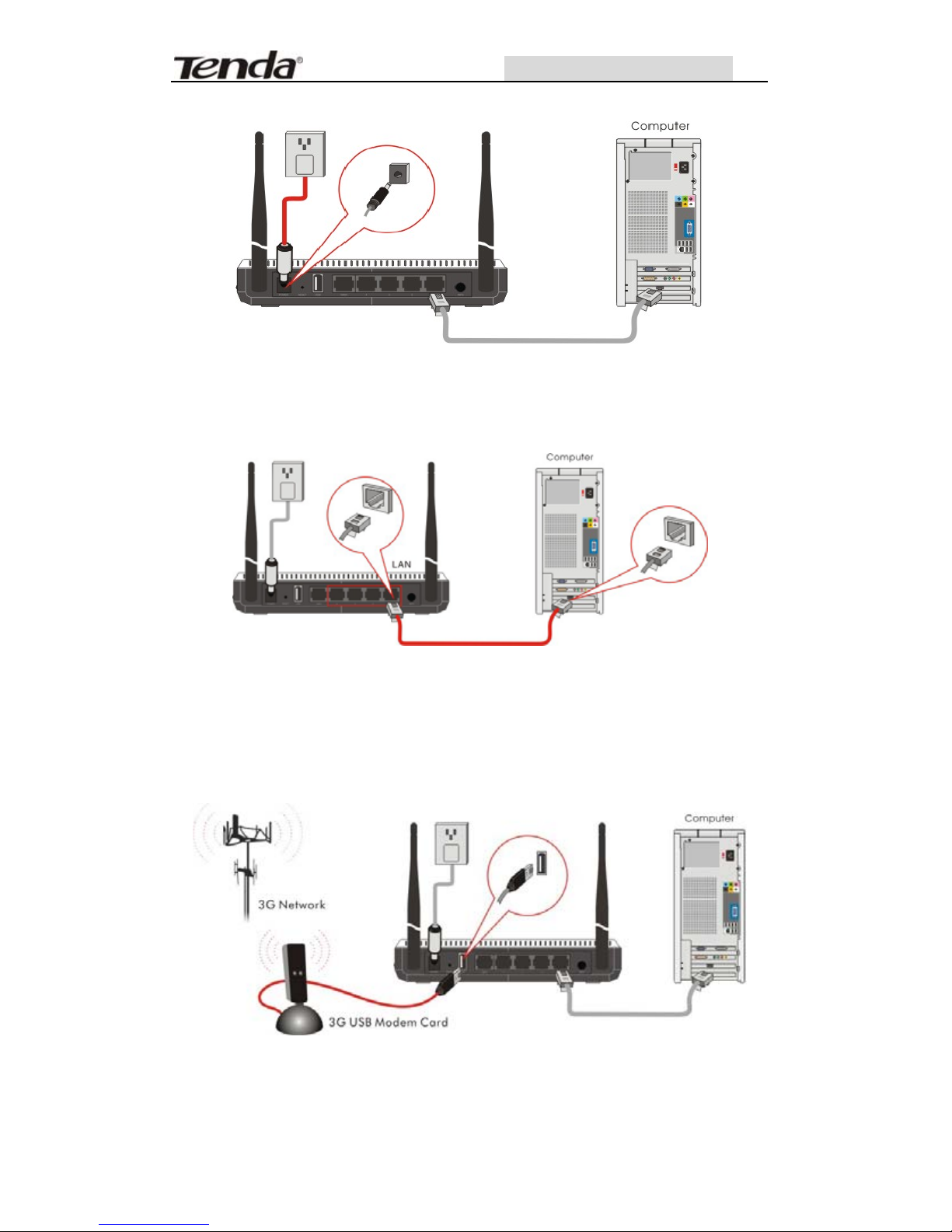
3G 11N Wireless Router
2. Please connect the LAN port of the Router to the
network adapter of your computer with a cable.
3. Connection between the Router and Network
A.
If you have a 3G USB modem card, please connect it
to the Router's USB port to share 3G network.
B. If you are provided the wired broadband by your ISP
to access the Internet, please connect the Router's WAN
8
Page 15

3G 11N Wireless Router
port with the Internet access line.
C. If you are provided the wireless broadband by your
ISP to access the Internet or you want to amplify
wireless signals, please set the Router's wireless WAN
feature.
4. Please insert the included CD-ROM into the CD-ROM
drive. You can run the “Setup Wizard” automati cally or
click the “Setup” button manually and then follow the
instructions to finish installation or enter the Router’s
Web-based utility to set the device. (For more details
please refer to chapter 3.)
9
Page 16

3G 11N Wireless Router
2.2 Network Application Plan
Usually Wireless LAN Network is deployed in a planned
environment where each access point is located in a
steady place with certain wireless coverage area for
communication service. Generally speaking, it is in the
center of the area to reduce “dead spot”.
1. Application Plan for 3G Network Connection
2. Application Plan for Wired Broadband Connection
10
Page 17

3G 11N Wireless Router
3. Application Plan for Wireless Broadband Connection
Chapter 3 How to Login to the Router
The chapter mainly presents how to enter the Router’s
Web page. After you have finished the hardware
installation (Please refer to chapter2.), the following
steps will assist you to set the network configurations
for you computer.
3.1 How to Set the Network Configurations
1. On your computer desktop right click “My Network
11
Page 18

3G 11N Wireless Router
Places” and select “Properties”.
12
Page 19

3G 11N Wireless Router
2. Right click “Local Area Network Connection” and
select “Properties”.
3 . Select “Internet Protocol (TCP/IP)” and click
“Properties”.
13
Page 20

3G 11N Wireless Router
4.Select “Obtain an IP address automatically” or select
“Use the following IP address (S)”.
A. “Obtain an IP address automatically” as the
following diagram:
B. “Use the following IP address (S)”
IP Address: 192.168.0.XXX: (XXX is a number
from 2~254)
Subnet Mask: 255.255.255.0
Gateway: 192.168.0.1
DNS Server: Certainly you need to input the DNS
server address provided by your ISP. Otherwise,
you can use the Router’s default gateway as the
DNS proxy server. Click “OK” to save the
configurations.
14
Page 21

3G 11N Wireless Router
Tip: If you are not sure of the DNS server address, we
recommend you to select “Obtain an IP address
automatically (O)” and “Obtain a DNS server address
automatically”.
3.2 Login to the Router
1.To access the Router’s Web-based interface, la unch
a web browser such as Internet Explorer and enter
the Router’s default IP address, http://192.168.0.1.
Press “Enter”.
2. Input the “admin” in both User Name and Password.
Click “OK”.
15
Page 22

3G 11N Wireless Router
3. If you enter the correct user name and password, the
screen will be the next one.
16
Page 23

3G 11N Wireless Router
Chapter 4 WAN Medium Type
4.1 WAN Medium Type
The Router provides three access medium types. If you
are provided the 3G broadband by your ISP to access
the Internet, you can connect the 3G USB modem card
to the Router’s USB port and select 3G WAN to set the
device. If you are provided the wired WAN access
broadband such as ADSL MODEM, CABLE MODEM or ISP
broadband access line, you can connect the access line
directly to the WAN port on the Router’s rear panel. In
addition, if you are provided the wireless broadband by
your ISP, you can access the Internet conveniently.
¾ 3G WAN: If you have a 3G USB modem card and
you want to share 3G signals and access the
17
Page 24

3G 11N Wireless Router
18
Internet, please select this type.
¾ Wired WAN: In this type the WAN link line must be
wired. Please connect the access line to the WAN
port on the Router’s rear panel. The default type is
wired WAN.
¾ Wireless WAN: If you are provided the wireless
WAN to access the Internet or you want to amp lify
the wireless signals, you can use this type.
Please select the different WAN medium type according
to the different access ways provided by your ISP . After
saving and rebooting the device, you can enter the
“
Setup Wizard” menu to set the connection type.
Chapter 5 Quick Setup Guide
This chapter deals with how to access the Internet
quickly.
After you enter the Router’s Web-based interface from
the Internet Explorer, pl ease select th e access m edium
type provided by your ISP in “WAN Medium”. After
saving and rebooting the device, please select your
connection type (PPPOE, Dynamic IP, and Static IP etc.)
provided by your ISP to finish the basic settings. Please
follow this guide to connect your Router to the Internet.
5.1 Setup Wizard
Page 25

3G 11N Wireless Router
5.1.1 3G Broadband Connection (via 3G WAN)
If you have a 3G USB modem card and you want to
share 3G signals and access the Internet, please select
“3G WAN” in “W AN Medium” after you enter the Router’s
Web-based interface.
Please follow the diagram below:
During the installation, please select the type of 3G
modem card and 3G ISP, then click “Apply” to finish the
settings. Other parameters will come out automatically .
Thus, it is very easy and fast for you to access the
internet.
For example: If you have ZTEMU350 3G card and the
ISP is China Mobile, you can select the card type and ISP
from the list, and then click “ Apply” to finish the settings.
After that, please go to system status to look over wan
port status. If it shows connected, you can access the
internet.
19
Page 26

3G 11N Wireless Router
Notice: After you have finished the settings and you still
can’t access the Internet, please use the wired
broadband to connect the Internet and visit our Website.
You can search the Model No. of your 3G USB Modem
card in the compatible products list to download the
corresponding upgrading firmware.
If you still can’t access the Internet, please contact the
3G modem card reseller and provide the Model No. of
the 3G modem card you have, we’ll try our best to help
you to solve the problem.
5.1.2 Wired Broadband Connection (via Wired
WAN)
If you are provided the wired broadband by your ISP to
access the Internet, please select “Wired WAN” in the
“WAN Medium” setup page after you enter the R outer’ s
Web-based interface. It takes effect after saving and
rebooting the device.
Shown as the diagram below:
20
Page 27

3G 11N Wireless Router
After saving and rebooting the device, you will enter the
Router’s Web-based interface again. Please click “Next”
as the diagram below:
The screen will show as the diagram below. The Router
supports multiple access ways such as ADSL PPPOE Dial,
Dynamic IP, static IP, etc. In this chapter, we introduce
you three common access way settings. If you are not
sure of your access way , you can enable the auto-detect
function to select your access way.
21
Page 28

3G 11N Wireless Router
¾ ADSL Virtual Dial-up (via PPPoE)
Enter the Account and Password provided by your ISP,
and click “Next”.
For example:
¾ Dynamic IP (via DHCP)
If your connection mode is Dynamic IP, it means your IP
address keeps changing every time you connect. Y ou do
not need to enter the information like other modes.
22
Page 29

3G 11N Wireless Router
Click “Next” and “Apply” to finish the settings.
¾ Static IP
In this screen , fill the network ad dress information from
your ISP in the IP Address, Subnet Mask, Gateway and
Primary DNS server fields and click “Next”.
For example:
ISP provides the following TCP/IP parameters as
follows:
IP Address:192.168.1.2
Subnet Mask:255.255.255.0
Gateway:192.168.1.1
Primary DNS Server:192.168.1.2
Alternate DNS Server:202.96.134.133
23
Page 30

3G 11N Wireless Router
Click “Apply” to complete the setup wizard. The Router
will record the settings you made. To activate the
settings, it is recommended to select “Reboot the
Router” from “System Tool” of the left menu. It is
rebooting now, please wait for a few minutes and DO
NOT power off it.
After rebooting the Router, you can click the “Running
Status” on the right menu to check the connection
between the Router and ISP device. If the status
information of the WAN port appears as the diagram
show, it means you have finished the Router’s basic
settings and you can surf on line now. If you want to
configure more, please refer to the following chapters.
24
Page 31

3G 11N Wireless Router
5.1.3 Wireless Broadband Connection (via Wireless
WAN)
If you are provided the wireless broadband by your ISP
to access the Internet or you want to amplify wireless
signals, please select “Wireless WAN” in “WAN Medium”
page after you enter the Router’s setup page.
Shown as the diagram below:
Please enter the wireless SSID, MAC address, channel,
security mode parameters provided by your Wi-Fi ISP. If
25
Page 32

3G 11N Wireless Router
you are not clear, please cli ck” Auto Scan” to finish the
settings. Select and save the settings, and you will enter
the Router’s Web interface again after rebooting the
Router. Then click “next” as the diagram show.
The screen will show as the diagram below. The Router
supports multiple access ways such as ADSL dial-up,
Dynamic IP, and Static IP etc. In this chapter, we
introduce you three common access way settings. If you
are not sure of your ISP access way , you can enable the
auto-detect function to select your access way.
26
Page 33

3G 11N Wireless Router
¾ ADSL Virtual Dial-up (via PPPoE)
This way is used when the Router is connected to the
wireless modem or you want to amplify wireless signals
and share the Internet with multiple computers. Enter
the Account and Password provided by your ISP, and
click “Next”. If you are not clear, please contact your
ISP.
For example:
If the Account is pppoe_user and Password is 123456,
you need to enter the information as the diagram below.
Please enter the Account and Password provided by
your ISP.
¾ Dynamic IP (via DHCP)
If you are provided the Dynamic IP connection mode by
your ISP or you want to amplify wireless signals, please
select “Obtain the IP address automatically”. Click
“Next” and “Save” to finish settings.
If the IP address of the WAN port is not 0.0.0.0 on the
Router’s running status Web page, it means you can
27
Page 34

3G 11N Wireless Router
access the Internet now. Generally speaking, the
wireless signals are amplified and you can share the
Internet with multiple computers.
Notice: When you open the wireless WAN feature or
when you have a wireless router before and you want to
amplify wireless signals, please pay attention to the IP
address the previous router distributed. If the IP
address belongs to the range: 192.168.0.x, you need to
change the LAN IP address to different range such as
192.168.2.1. Only this way, you can amplify the
wireless signals and access the Internet. Please refer to
chapter 6.1 for changing method.
The wireless broadband which connected to ISP doesn’t
need to change its LAN IP.
¾ Static IP
In this screen, if you are provided the static IP, pl ease
select “Ethernet Broadband, Static IP Address” and fill
the network address information from your ISP in the IP
Address, Subnet Mask, Gateway, Primary DNS server
28
Page 35

3G 11N Wireless Router
and Alternate DNS Server fields and click “Next”.
For example:
ISP provides the following TCP/IP parameters as
follows:
IP Address:192.168.1.2
Subnet Mask:255.255.255.0
Gateway:192.168.1.1
Primary DNS Server:210.21.196.6
Secondary DNS Server:211.5.88.88
You need to fill in the related parameters.
Click “Save” to complete the setup wizard. The Router
will record the settings you made. To activate the
settings, it is recommended to select “Reboot the
Router” from “System Tool” of the left menu. It is
rebooting now, please wait for a few minutes and DO
NOT power off it. Please use the new parameters to run
the Router.
29
Page 36

3G 11N Wireless Router
After rebooting the Router, you can click the “Running
Status” on the right menu to check the connection
between the Router and ISP device. If the status
information of the WAN port appears as the diagram
show, it means you have finished the Router’s basic
settings and you can surf on line now. If you want to
configure more, please refer to the following chapters.
Notice:
The difference between wired WAN and wireless WAN is
the connection medium type. Generally speaking, the
standard twisted-pair is used to connect the Router’s
WAN port in wired WAN connection type. However,
30
Page 37

3G 11N Wireless Router
31
wireless signals in standard 2.4GHZ frequency range
are used as the transmitting medium in wireless WAN
connection type. When you use wireless WAN or 3G
WAN, please make sure that the wireless network exists
and the intensity and performance of wireless signals
are OK. The methods to confirm the wireless feature are
very simple.
The following methods are used to confirm the wireless
feature by connecting one computer to the Internet via
wireless broadband.
1. Confirm 3G signals. Please connect your computer
with a 3G modem card to access the Internet. If the
signals are OK and the speed is fast at the place, you
can connect the wireless Router here to share 3G
connection and access the Internet.
2. Confirm Wi-Fi signals. Connect your computer to
wireless broadband or other wireless Router by a
wireless adapter. If it can access the Internet, it means
you can use the wireless feature of the Router and
amplify wireless signals at this place. If the computer
can’t find wireless signals at some place, you need to
change the Router’s place for receiving better signals
and using wireless WAN feature better.
3. Confirm wired WAN signals. The wired WAN access
way is the most traditional among the three access
ways of the Router. If you can use one computer to
access the Internet, you can use the wired WAN
Page 38

3G 11N Wireless Router
function of the Router.
Chapter 6 Advanced Settings
6.1 LAN Settings
LAN Settings are for the basic TCP/IP parameters of LAN
ports.
¾ MAC Address: The Router’s physical MAC address
as seen on your local network is unchangeable.
¾ IP Address: The Router’s LAN IP addresses (not
your PC’s IP address). 192.168.0.1 is the default
value.
¾ Subnet Mask: It’s shown the Router’s subnet
mask for measurement of the network size.
255.255.255.0 is the default value.
Notice:
Once you modify the IP address, you need to
remember it for the Web-based Utility login next
time.
32
Page 39

3G 11N Wireless Router
6.2 WAN Settings
After you have selected the ISP connection type in
“Setup Wizard” and you want to modify the related
settings, here you can modify and configure the settings
in details.
Virtual Dial-up(PPPoE)
¾ WAN Connection Mode: Show your current
connection mode.
¾ Account: Enter them provided by your ISP.
¾ Password: Enter them provided by your ISP.
¾ MTU: Maximum Transmission Unit. It is the size of
largest datagram that can be sent over a network.
The default value is 1492. Do NOT modify it unless
necessary. But if some specific website or web
33
Page 40

3G 11N Wireless Router
34
application software can not be open or enabled,
you can have a try to change the MTU value as
1450, 1400, etc.
¾ Service Name: It is defined as a set of
characteristics that are applied to a PPPoE
connection. Enter it if provided. Do NOT modify it
unless necessary.
¾ AC Name: Enter it if provided. Do NOT modify it
unless necessary.
¾ Connect Automatically: Connect automatically
to the Internet after rebooting the system or
connection failure.
¾ Connect Manually: Connect to the Internet by
users manually.
¾ Connect on Demand: Re-establish your
connection to the Internet after the specific time
(Max Idle Time). Zero means your Internet
connection at all time. Otherwise, enter the
minutes to be elapsed before you want to
disconnect the Internet access.
¾ Connect on Fixed Time: Connect to the Internet
during the time you fix.
Notice:
The “Connect on Fixed Time” can be deployed only
when you have set the current time in “Time
Settings” from “System Tool s”.
Page 41

3G 11N Wireless Router
Static IP
If your connection mode, static IP is chosen, you can
modify the following addressing information.
¾ IP Address: Here enter the WAN IP address
provided by your ISP.
¾ Subnet Mask: Enter the WAN Subnet Mask
here.
¾ Gateway: Enter the WAN Gateway here.
¾ Primary DNS Server: Enter the Primary DNS
server provided by your ISP.
¾ Secondary DNS Server: Enter the secondary
DNS.
As for PPTP and L2TP connection settings, please refer
to the “Wizard Setup” in chapter 5.
35
Page 42

3G 11N Wireless Router
3G WAN:
Network settings
¾ 3G modem card type: choose the Model No. of
your 3G USB modem card.
¾ PIN code: SIM card personal identification code.
Enter them provided by your ISP.
¾ Access Point Name: Enter them provided by your
ISP.
¾ Dial: Dial number, consult ISP for correct
parameters.
Advanced PPP Settings
¾ User Name: PPP Authentication User Name. Some
ISP need to enter this value.
36
Page 43

3G 11N Wireless Router
37
¾ Password: PPP Authentication Password. Some
ISPs need to enter this value.
Internet connection option:
There are four kinds of connection methods: connect
automatically, connect manually, connect on demand
and connect on fixed time. Please select one of them
according to your needs.
¾ Connect Automatically: Connect automatically
to the Internet after rebooting the system or
connection failure.
¾ Connect Manually: Connect to the Internet by
users manually.
¾ Connect on Demand: Re-establish your
connection to the Internet after the specific time
(Max Idle Time). Zero means your Internet
connection at all time. Otherwise, enter the
minutes to be elapsed before you want to
disconnect the Internet access.
¾ Connect on Fixed Time: Connect to the Internet
during the time you fix.
Note: it is sug gested you c hoosing Conne ct on Demand
without running up bills, because it can disconnect the
internet automatically when there is no data
transmitting or the computer closed. If you access the
internet, it will dial up automatically which is very
convenient.
Page 44

3G 11N Wireless Router
If your ISP doesn’t offer you the related parameters,
you do not need to enter them. After configuring the
settings correctly, click “Apply” button and wait for 60
seconds. Then you can access the Internet.
6.3 MAC Address Clone
This page is for the Router’s MAC address to WAN.
Some ISPs require end-user's MAC address to access
their network. This feature copies the MAC address of
your network device to the Router.
¾ MAC Address: The MAC address to be registered
with your Internet service provider.
¾ Clone MAC Address: Register your PC's MAC
address.
¾ Restore Default MAC Address:
Restore to the
default hardware MAC address.
6.4 DNS Settings
DNS is short for Domain Name System (or Service), an
38
Page 45

3G 11N Wireless Router
Internet service that translate domain names into IP
addresses which are provided by your Internet Service
Provider. Please consul t your Internet Service Provider
for details if you do not have them.
¾ DNS: Click the checkbox to enable the DNS server.
The Router’s DHCP sever will answer the client’s
requests and distribute DNS address.
¾ Primary DNS Address: Enter the necessary
address provided by your ISP.
¾ Secondary DNS Address: Enter the second
address if your ISP provides, which is optional.
Notice: After the settings are completed, reboot
the device to activate the modified settings.
39
Page 46

3G 11N Wireless Router
Chapter 7 Wireless Setting
7.1 Basic Settings
¾ Enable Wireless: Check to enable the Router’s
wireless features; uncheck to disable it.
¾ Network Mode : Select one mode from the
following. The default is 11b/g/n mode.
40
Page 47

3G 11N Wireless Router
41
11b mode: Allow the wireless client to connect
with the device in 11b mode at the
maximum speed of 11Mbps.
11g mode: Allow the 11g/11n-compliant client
device to connect with the AP at the
maximum speed of 54Mbps.
11b/g mode: Allow the 11b/g-compliant client
device to connect with the AP with
auto-negotiation speed, and 11n
wireless client to connect the device
with 11g speed.
11b/g/n mode: Allow 11b/g/n-compliant client
device to connect with the AP with
auto-negotiation speed
¾ Main SSID:SSID (Service Set Identifier) is the
unique name of the wireless network. This device
has two SSID and the main SSID is necessary.
¾ Minor SSID:It is optional.
¾ Broadcast (SSID): Select “Enable” to enable the
device's SSID to be visible by wireless clients. The
default is enabled.
¾ MBSSID AP Isolation : One access control
feature based on wireless MAC address. When this
feature is enabled, wireless clients connected with
the same SSID can not communicate with each
other. For example, configure main SSID as AP1,
minor SSID as AP2. PC1 and PC2 connect to AP1
Page 48

3G 11N Wireless Router
42
via wireless adapter, and configure PC1 and PC2 in
the same segment. After the feature is enabled,
two PCs can not communicate and share network
resource each other, but they can communicate
with wireless clients connected with AP2. This
feature is to isolate the communication of wireless
clients connected with the same SSID.
¾ AP Isolation: One access control feature based on
SSID. When this feature is enabled, each of your
wireless clients will be in its own virtual network
and will not be able to communicate with each
other. When this feat ure is enabled, wireless clients
connected with the Main SSID and Minor SSID can
not communicate with each other , which can secure
the wireless network strongly. For example,
configure main SSID as AP1, minor SSID as AP2.
PC1 connects to AP1 via wireless adapter; PC2
connecting to AP2. After the feature is enabled, two
PCs can not communicate and share network
resource each other. Thi s feature is to isolate the
communication of wireless clients connected with
different SSID.
Tip: If you want to isolate all connected
wireless client's communication, please
enable MBSSID AP Isolation and AP Isolation
simultaneously.
¾ BSSID:Basic Service Set Identifier of wireless
network. In IEEE802.11, BSSID is the MAC address
of wireless access point.
Page 49

3G 11N Wireless Router
43
¾ Standard Channel:Specify the effective channel
(from 1 to 13\Auto) of the wireless network.
¾ Extension Channel:To increase data throughput
of wireless network, the extension channel range is
used in 11n mode.
¾ Channel Bandwidth : Select the channel
bandwidth to improve the wireless performance.
When the network has 11b/g and 11n clients, you
can select the 40M; when it is an 11n network,
select 20/40M to improve its throughput.
7.2 Wireless Security Setting
It is used to configure the AP network’s security setting.
Here presents the common six (ten in all) encryption
methods, including WPA-personal, WPA2-personal,
Mixed WEP, WPA-enterprise, WPA2-enterprise, etc.
7.2.1 WPA-Personal
WPA (Wi-Fi Protected Access), a Wi-Fi standard, is a
more recent wireless encryption scheme, designed to
improve the security features of WEP. It applies more
powerful encryption types (such as TKIP [Temporal Key
Integrity Protocol] or AES [Advanced Encryption
Standard]) and can change the keys dynamically on
every authorized wireless device.
Page 50

3G 11N Wireless Router
¾ WPA Algorithms:Provides TKIP [Temporal Key
Integrity Protocol] or AES [Advanced Encryption
Standard].
¾ Pass Phrase: Enter the encrypted characters with
8-63 ASCII characters.
¾ Key Renewal Interval:Set the key’s renewal
period.
7.2.2 WPA2- Personal
WPA2 (Wi-Fi Protected Access version 2) provides
higher security than WEP (Wireless Equivalent Privacy)
or WPA (Wi-Fi Protected Access). Besides TKIP
encryption, new AES encryption mode is provided.
44
Page 51

3G 11N Wireless Router
¾ WPA Algorithms:Provides TKIP [Temporal Key
Integrity Protocol], AES [Advanced Encryption
Standard] or TKIP&AES mixed mode.
¾ Pass Phrase:Enter the encrypted characters with
8-63 ASCII characters.
¾ Key Renewal Interval:Set the key’s renewal
period.
7.2.3 Mixed WEP
WEP (Wired Equivalent Privacy), a basic encryption
method, usually encrypts wireless data using a series of
digital keys (64 bits or 128 bits in length). By using the
same keys on each of your wireless network devices,
you can prevent unauthorized wireless devices from
45
Page 52

3G 11N Wireless Router
monitoring your transmissions or using your wireless
resources. Select Mixed WEP to enter the following
window:
¾ Select SSID: Select the SSID (main SSID or
minor SSID) to configure security setting from the
drop-down menu.
¾ Security Mode:From the drop-down menu select
the corresponding security encryption modes.
¾ WEP Key:Set the WEP key with the format of
ASCII and Hex.
¾ Key Explanation: You can enter ASCII code (5 or
13 ASCII characters. Illegal character as “/” is not
allowed.) Or 10/26 hex characters.
¾ Default Key : Select one key from the four
configured keys as the current available
46
Page 53

3G 11N Wireless Router
7.2.4 WPA- Enterprise
This security mode is used when a RADIUS server is
connected to the device. Select “WPA-Enterprise” from
the drop-down menu to enter the following window:
¾ WPA Algorithms:Provides TKIP [Temporal Key
Integrity Protocol] or AES [Advanced Encryption
Standard].
¾ Key Renewal Interval:Set the key’s renewal
period.
¾ Radius Server Address:Enter the IP address of
the Radius server.
¾ Radius Server port: Enter the authentication
47
Page 54

3G 11N Wireless Router
port of the Radius server. The default is 1812.
¾ Shared Key : Enter the shared key for
authentication server with 8~63 ASCII characters.
¾ Session Timeout : The authentication interval
period between the Router and authentication
server.
7.2.5 WPA2-Enterprise
This security mode is based on Radius authentication
server and WPA2 encryption method. WPA2 is used
when a RADIUS server is connected to the device.
Select “WPA2-Enterprise” from the drop-down menu to
enter the following window:
48
Page 55

3G 11N Wireless Router
49
¾ WPA Algorithms:Provides TKIP [Temporal Key
Integrity Protocol] or AES [Advanced Encryption
Standard].
¾ Key Renewal Interval:Set the key’s renewal
period.
¾ Radius Server Address:Enter the IP address of
the Radius server.
¾ Radius Server port: Enter the authentication
port of the Radius server. The default is 1812.
¾ Shared Key : Enter the shared key for
authentication server with 8~63 ASCII characters.
¾ Session Timeout: The authentication interval
period between the Router and authentication
server. The default is 3600s.
7.2.6 802.1X
This security mode is used when a RADIUS server is
connected to the device. 802.1x, a kind of Port-based
authentication protocol, is an authentication type and
strategy for users. The port can be either a physic port
or logic port (such as VLAN). For wireless LAN users, a
port is just a channel. The final purpose of 802.11x
authentication is to check if the port can be used. If the
port is authenticated successfully, you can open this
port which allows all the messages to pass. If the port
isn’t authenticated successfully, you can keep this port
“disable” which just allows 802.1x authentication
Page 56

3G 11N Wireless Router
protocol message to pass. Select “802.1 x” from the
drop-down menu to enter the following window:
¾ WEP:Click “Enable/Disable” to enable or disable
the WEP algorithm.
¾ Radius Server Address:Enter the IP address of
the Radius server.
¾ Radius Server Port: Enter the authentication
port of the Radius server. The default is 1812.
¾ Shared Key : Enter the shared key for
authentication server with 8~63 ASCII characters.
¾ Session Timeout : The authentication interval
period between AP and authentication server. The
50
Page 57

3G 11N Wireless Router
default is 3600s.
Note: To improve security level, do not use too
easy characters. If you are not familiar with these
ten security modes, it is recommended to use
“WPA-Personal” mode.
Wireless Security Settings 802.11n only defines
three standard encryption methods: Open-None
(Disable), WPA-Personal-AES, PA2-Personal-AES.
Other encryption methods are nonstandard.
There may be compatibility problems among
different manufacturers.
7.3 Advanced Settings
This section is to configure the advanced wireless
setting of the Router, including the BG Protection Mode,
Basic Data Rates, Fragmentation Threshold, RTS
Threshold, and WMM etc.
51
Page 58

3G 11N Wireless Router
52
¾ BG protection Mode: Auto by default. It is for
11b/g wireless client to connect 11n wireless
network smoothly in a complicated wireless area.
¾ Basic Data Rates: For different requirement, you
can select one of the suitable Basic Data Rates.
Here, default value is (1-2-5.5.-11Mbps…). It is
recommended not to modify this value.
¾ Beacon Interval: Set the beacon interval of
wireless radio. Default value is 100. It is
recommended not to modify this value.
¾ Fragment Threshold: The fragmentation
threshold defines the maximum transmission
packet size in bytes. The packet will be fragmented
if the arrival is bigger than the threshold setting.
The default size is 2346 bytes. It is recommended
not to modify this value.
¾ RTS Threshold: RTS stan ds for “Request to Send” .
This parameter controls what size data packet the
frequency protocol issues to RTS packet. The
default value of the attribute is 2346. It is
recommended not to modify this value in SOHO
environment.
¾ TX Power: Set the output power of wireless radio.
The default value is 100.
¾ WMM Capable: It will enhance the data transfer
performance of multimedia data when they’re
being transferred over wireless network. It is
recommended to enable this option.
Page 59

3G 11N Wireless Router
¾ APSD Capable: It is used for auto power-saved
service. The default is disabled.
7.4 WPS Settings
WPS (Wi-Fi Protected Setting) can be easy and quick to
establish the connection between the wireless network
clients and the device through encrypted contents. The
users only enter PIN code or press WPS button on the
panel to configure it without selecting encryption
method and secret keys by manual. In the “Wireless
settings” menu, click “WPS settings” to enter the next
screen.
¾ WPS settings:T o enable or disable WPS function.
The default is “disable”.
¾ WPS mode:Provide two ways: PBC (Push-Button
53
Page 60

3G 11N Wireless Router
54
Configuration) and PIN code.
¾ PBC:Select the PBC or press the WPS button on
the front panel of the device for about one second
(Press the button for about one second and WPS
indicator will be blinking for 2 minutes, which
means the WPS is enabled. During the blinking
time, you can enable another device to implement
the WPS/PBC negotiation between them. Two
minutes later, the WPS i ndicator will be off, whi ch
means the WPS connection is completed. If more
clients are added, repeat the above steps. At
present, the WPS supports up to 32 clients access.)
¾ PIN:If this option is enabled, you need to enter a
wireless client’s PIN code in the field and keep the
same code in the WPS client.
¾ WPS Summary: Show the current state of Wi-Fi
protected setting, including authorized mode,
encryption type, default key and other information.
¾ WPS Current Status: Idle means WPS in idle
state. Start MSC process means the process has
been started and waits for being connected.
Configured means the negotiation is successful
between server and clients.
¾ WPS Configured: “yes” means WPS feature is
enabled and goe s into effect. “not used” mea ns it is
not used. Usually the AP-security has been enabled,
here will displayed “not used”.
¾ WPS SSID: Show the main SSID set by WPS.
¾ WPS Auth. Mode : The authorization mode
Page 61

3G 11N Wireless Router
deployed by WPS, generally WPA/WPA2-personal
mode.
¾ WPS Encrypt Type:The encryption type used by
WPS, generally AES/TKIP.
¾ WPS key: The effective key generated by AP
automatically.
¾ AP PIN(KEY):The PIN code used by default.
¾ Reset OOB: When this button is pressed, the
WPS client will be idle state, and WPS indicator will
be turned off. AP will not respond the WPS client’s
requests and the set the security mode as WPA
mode.
7.5 WDS Settings
WDS (Wireless Distribution System) is used to expand
wireless coverage area. This Router provides three
modes: Lazy, Bridge and Repeater.
Lazy: In this mode, the connected device can be Bridge
mode or Repeater mode and enter the Router’s BSSID
55
Page 62

3G 11N Wireless Router
56
to establish the connection.
Bridge Mode: You can wirelessl y connect two or more
wired networks via this mode. In this mode, you need to
add the Wireless MAC address of the connecting device
into the Router's AP MAC address table or select one
from the scanning table.
Repeater Mode:In this mode, add the opposing MAC
address into each own AP MAC address table by manual
or scanner to enlarge and extend the wireless radio.
Encrypt Type: Select one from WEP, TKIP, AES for
security here.
Pass phrase: Enter the encrypted key for wireless
devices.
AP MAC Address: Input the MAC address of another
(opposing) wireless router you want to connect.
NOTE: It is recommended that two wireless
routers keep the same bandwidth, channel
number, and security settings. Apply the settings
and reboot the Router to activate it.
7.6 Wireless Access Control
T o secure your wireless LAN, the wireless access control
is actually based on the MAC address management to
allow or block the specific clients to access the wireless
network. Select “Wireless Setting->Access Control” to
display the following screen:
Page 63

3G 11N Wireless Router
¾ MAC Address Filter:Enable/disable MAC address
filter. Select “off” to malfunction MAC address;
“disable” to prevent the MAC addresses in the list
from accessing the wireless network; “Allow” to
allow the MAC address in the list to access the
wireless network.
¾ MAC Address Management : Input the MAC
address to implement the filter policy. Click “Add”
to finish the MAC add operation.
¾ MAC Address list : Show the added MAC
addresses. You can add or delete them.
7.7 Connection Status
This page shows wireless client’s connection status,
including MAC address, Channel bandwidth, etc. Sel ect
“Wireless Setting->connection status” to enter the
following screen:
57
Page 64

3G 11N Wireless Router
¾ MAC Address:Shows current MAC addresses of
the hosts connecting to the Router.
¾ Bandwidth:Shows current frequency bandwidth
the wireless client used.
Chapter 8: DHCP Server
8.1 DHCP Settings
DHCP (Dynamic Host Control Protocol) is to assign an IP
address to the computers on the LAN/private network.
When you enable the DHCP Server , the DHCP Server will
allocate automatically an unused IP address from the IP
address pool to the requesting computer in premise of
activating “Obtain an IP Address Automatically”. So
specifying the starting and ending address of the IP
Address pool is needed.
58
Page 65

3G 11N Wireless Router
¾ DHCP Server: Activate the checkbox to
enable DHCP server.
¾ IP Address Start/End: Enter the range of IP
address pool for DHCP server distribution.
¾ Lease Time: The length of the IP address l ease.
For example:
If the lease time is an hour, then DHCP server will
reclaim the IP address each hour.
8.2 DHCP List and Binding
The Static I P assignment is to add a spec ifically static I P
address to the assigned MAC address. Y ou can view the
related information in the DHCP server list.
59
Page 66

3G 11N Wireless Router
¾ IP Address: Enter the IP address which needs to
be bound.
¾ MAC Address: Enter the MAC address of the
computer you want to assign the above IP address.
Click “Add” to add the entry in the list.
¾ Hostname: The name of the computer which is
added a new IP address.
¾ Lease Time: The left time length of the
corresponding IP address lease.
60
Page 67

3G 11N Wireless Router
Chapter 9 Virtual Server
9.1 Single Port Forwarding
The Router can be configured as a virtual server on
behalf of local services behind the LAN port. The given
remote requests will be re-directed to the local servers
via the virtual server. This section deals with the single
port forwarding mainly. The Single Port Forwarding
allows you to set up kinds of public services such as web
servers, ftp, e-mail and other specialized Internet
applications on your network.
¾ External Port: This is the external (WAN) port
number for server or Internet application, for
example, port 21 for ftp service.
61
Page 68

3G 11N Wireless Router
62
¾ Internal Port: This is the port number of LAN
computer set by the Router. The Internet traffic
from the external port will forward to the internal
port. For example:you can set the internal port
NO.66 to act as the external port NO.21 for ftp
service.
¾ IP Address: Enter the IP address of the PC where
you want to set the applications.
¾ Protocol: Select the protocol (TCP/UDP/Both) for
the application.
¾ Delete/Enable: Click to ch eck it for corresponding
operation.
¾ Well-Known Service Port: Select the well-known
services as DNS, FTP from the drop-down menu to
add to the configured one above.
¾ Add: Add the selected well-known port to the
policy ID.
For example:
Y ou can establish a WEB server at the computer with the
IP address of 192.168.0.10 in LAN and the server use
the port of 80. If you can visit the WEB server in WAN
when you enter http://x.x.x.x:40, you can enter 40 at
the “WAN Ports “on this page and enter 80 at the “LAN
Ports”. “LAN IP” set 192.168.0.10. “Protocol” selects all.
It takes effect after saving the settings.
Page 69

3G 11N Wireless Router
NOTE: If you set the virtual server of the service
port as 80, you must set the Web management
port on Remote Web Management page to be any
value except 80 such as 8080. Otherwise, there
will be a conflict to disable the virtual server.
9.2 Port Range Forwarding
This section deals with the port range forwarding mainly .
The Port Range F orwarding allows you to set up a ra nge
of public services such as web servers, ftp, e-mail and
other spe cialized Int ernet applicatio ns to an assig ned IP
address on your LAN.
63
Page 70

3G 11N Wireless Router
64
¾ Start/End Port: Enter the start/end port number
which ranges the External ports used to set the
server or Internet applications.
¾ IP Address: Enter the IP address of the PC where
you want to set the applications.
¾ Protocol: Select the protocol (TCP/UDP/Both) for
the application.
¾ Delete/Enable: Click to check it fo r corresponding
operation.
¾ Well-Known Service Port: Select the well-known
services as DNS, FTP from the drop-down menu to
add to the configured one above.
¾ Add: Add the selected well-known port to the
policy ID.
For example:
The server at the IP address of 192.168.0.10 in LAN
provides WEB service at the port of 80 and Telnet
service at the port of 23. If you want the clients on the
Internet to visit this server, please set the device as the
diagram above.
NOTE: If you set the virtual server of the service
port as 80, you must set the Web management
port on Remote Web Management page to be any
value except 80 such as 8080. Otherwise, there
will be a conflict to disable the virtual server.
Page 71

3G 11N Wireless Router
9.3 ALG Service Settings
In the context of computer networking, an ALG or
application layer gateway consists of a security
component that augments a firewall or NAT employed in
a computer network. It allows customized NA T traversal
filters to be plugged into the gateway to support
address and port translation for certain application layer
"control/data" protocols such as FTP, BitTorrent, SIP,
RTSP, file transfer applications etc.
In order for these protocols to work through NAT or a
firewall, either the application has to know about an
address/po rt numbe r combin ation th at a llows in comin g
packets, or the NAT has to monitor the control traffic
and open up port mappings (firewall pinhole)
dynamically as required. Legitimate application data
can thus be passed through the security checks of the
firewall or NA T that would have otherwise restricted the
traffic for not meeting its limited filter criteria.
65
Page 72

3G 11N Wireless Router
66
Usually allowing client applications to use dynamic
ephemeral TCP/ UDP ports to communicate with the
known ports used by the server applications, even
though a firewall-configuration may allow only a limited
number of known ports. In the absence of an ALG,
either the ports would get blocked or the network
administrator would need to explicitly open up a large
number of ports in the firewall; rendering the network
vulnerable to attacks on those ports.
In the default ALG settings, the following protocols have
enabled. It is recommended to keep the settings
unchanged.
1. FTP
2. TFTP
3. PPTP
4. IPSec
5. L2TP
9.4 DMZ Settings
The DMZ function is to allow one computer in LAN to be
exposed to the Internet for a special-purpose service as
Internet gaming or videoconferencing.
Page 73

3G 11N Wireless Router
¾ DMZ Host IP Address: The IP address of the
computer you want to expose.
¾ Enable: Click the checkbox to enable the DMZ
host.
For example:
Set the computer at the IP address of 192.168.0.10 in
LAN as a DMZ Host to intercommunicate with another
host on the Internet.
IMPORTANT:
When the DMZ host is enabled, the firewall settings of
the DMZ host will not function.
9.5 UPNP Settings
It supports latest Universal Plug and Play. This function
goes into effect on Windows XP or Windows ME or this
function would go into effect if you have installed
software that supports UPnP. With the UPnP function,
host in LAN can request the router to process some
special port switching so as to enable host outside to
visit the resources in the internal host.
67
Page 74

3G 11N Wireless Router
¾ Enable UPnP: Click the checkbox to enable the
UPnP.
Chapter 10 Traffic Control
10.1 Traffic Control
Traffic control is used to limit communication speed in
the LAN and WAN. Up to 20 entries can be supported
with the capability for at most 254 PCs' speed control,
including for IP address range configuration.
68
Page 75

3G 11N Wireless Router
¾ Enable Traffic Control: To enable or disable the
internal IP bandwidth control. The default is
disabled.
¾ Interface: To limit the up loading and d ownloading
bandwidth in WAN port.
¾ Service: T o select the controlled service type, such
as HTTP service.
¾ IP Starting Address: The first IP address for
traffic control.
¾ IP Ending Address: The last IP address for traffic
control.
¾ Uploading/Downloading: To specify the traffic
heading way for the selected IP addresses:
uploading or downloading.
¾ Bandwidth: T o specify the uploading/downloadin g
69
Page 76

3G 11N Wireless Router
Min. /Max. Traffic speed (KB/s), which can not
exceed the WAN speed.
¾ Apply: To enable the current editing rule. If not,
the rule will be disabled.
¾ Add: After edit the rule, click the “add to list”
button to add the current rule to rule list.
¾ Apply: Click “Save” to activate the current rule.
¾ Cancel: Click “Cancel” to drop all setting saved last
time.
10.2 Traffic Statistics
Traffic statistics is used to show the LAN PC’s traffic
information.
¾ Enable traffic statistics: check to enable traffic
statistics. Usually traffic statistics is disabled,
which can improve the Router’ s data handling. The
default is disabled. If it is enabled, the page will
update the PC’s traffic information automatically
and be refreshed every 5 seconds.
¾ IP address: The IP address to be shown.
¾ Upstream rate: the speed of upstream data per
second (Kbyte/S).
70
Page 77

3G 11N Wireless Router
71
¾ Downstream rate: the speed of downstream data
per second (Kbyte/S).
¾ Sending packet: The PC’s packets sending from
the PC.
¾ Sending byte: The byte (Mbyte) sending from the
PC.
¾ Receiving packet: The PC’s packets received
from the Router.
¾ Receiving byte: The PC’s byte (Mbyte) received
from the Router.
Chapter 11 3G WAN Traffic and
Connection Timer
11.1 3G WAN Traffic
In 3G WAN mode, 3G WAN tr affic function is supported.
Click "3G WAN traffic" you can check the router's
Internet traffic, transmission rate, transmission data
volume and traffic for nearly two months, so that you
can know how much the traffic that the 3G modem card
accesses the Internet without running up bills.
Page 78

3G 11N Wireless Router
Notice: this function is only for 3G WAN.
In 3G Router mode, 3G WAN traffic is used to calculate
the traffics of W AN port. Click “3GW AN Traffic” then y ou
can inquiry the status such as the status
11.2 Connection Timer
In 3G WAN mode, Connection Timer function is
supported. Click “System Status" then you can see the
WAN port connection time, internet access time of this
month and other status.
72
Page 79

3G 11N Wireless Router
Note: The result of 3G WAN Traffic and Connection
Timer are only for reference. This device can only
calculate the status that the 3G modem card plugs into
the device. The actual statistics is subject to the ISP.
Chapter12 URL Monitor
12.1 URL Monitor
This feature is used to record user’s Internet activity , so
in terms of this feature, the administrator can check out
and control what they can do and have done.
¾ Enable URL Monitor:
After checking this feature, the Router will record
LAN computer’s URL information, including the
73
Page 80

3G 11N Wireless Router
74
visiting Website, your LAN IP address and the time.
The Router can record up to 500 entries. If the
record is more than 500 entries, the counter will
clean all records and restart the URL record again.
If the Router is powered off and restarts the device,
the records will be also lost. The default setting is
disabled.
¾ Enable Email: To enable this feature, the URL
records will be sent to specified e-mail, which can
be solved the problem that the records will be lost
when it is over 500 entries.
¾ Receive E-mail Address: Input the received
E-mail’s address here. For example:
tenda@sina.com.cn
¾ SMTP Server Address: Input the SMTP server
address here. If you are not clear what your SMTP
server’s address is, you can find them from Help
page of the registered e-mail. For example:
smtp.sohu.com, smtp.163.com, etc.
¾ Send Email Address: Input the sending email
address here.
¾ User Name: Input the sending e-mail’s user
name.
¾ Email Password: Input the sending e-mail’s
password.
¾ Time Triggering Interval: To set sending
e-mail’s time interval. The time ranges from 30 to
Page 81

3G 11N Wireless Router
75
1440 minutes.
For example: if you input 30 here, it means the
Router will send an email from “Send Email
Address” to “Receive Email Address” in every 30
minutes. And then the device will clean all records
and start the recording again.
¾ Entry Triggering Interval: To set sending
e-mail’s entry interval. The entry ranges from 100
to 500.
For example:
If you input 100 here, it means the Router will send an
email from “Send Email Address” to “Receive Email
Address” every 100 entries. And then the device will
clean all records and start the recording again.
Chapter 13 Security Settings
13.1 Client Filter Settings
To benefit your further management to the computers
in the LAN, you can control some ports access to
Internet by data packet filter function.
Page 82

3G 11N Wireless Router
¾ Client Filter: Check to enable client filter.
¾ Access Policy: Select one number from the
drop-down menu.
¾ Enable: Check to enable the access policy.
¾ Clear the Policy: Click “Clear” button to clear all
settings for the policy.
¾ Filter Mode: Click one radio button to enable or
disable to access the Internet.
¾ Policy Name: Enter a name for the access policy
selected.
¾ IP Start/End: Enter the starting/ending IP
address.
¾ Port No.: Enter the port range based over the
protocol for access policy.
¾ Protocol: Select one protocol (TCP/UDP/Both)
76
Page 83

3G 11N Wireless Router
77
from the drop-down menu.
¾ Times: Select the time range of client filter.
¾ Days: Select the day(s) to run the access policy.
For example:
If you don’t want the computer at the IP address of
192.168.0.100 to access the Internet from 9:00 to
18 : 00 everyday without restrictions to other
computers in LAN, you need to set the packet filtering
list as the above diagram.
13.2 URL Filter Settings
In order to control the computer to have access to
websites, you can use URL filtering to allow the
computer to have access to certain websites at fixed
time and forbids it having access to certain websites at
fixed time.
Page 84

3G 11N Wireless Router
¾ URL Filter: Check to enable URL filter.
¾ Access Policy: Select one number from the
drop-down menu.
¾ Enable: Check to enable the access policy.
¾ Clear the Policy: Click “Clear” button to clear all
settings for the policy.
¾ Filter Mode: Click one radio button to enable or
disable to access the Internet.
¾ Policy Name: Enter a name for the access policy
selected.
¾ Start/End IP: Enter the starting/ending IP
address.
¾ URL Strings: Specify the text strings or keywords
needed to be filtered. If any part of the URL
contains these strings or words, the web page will
not be accessible and displayed.
¾ Times: Select the time range of client filter.
78
Page 85

3G 11N Wireless Router
¾ Days: Select the day(s) to run the access policy.
¾ Save: Select Save to enable the settings.
For example:
If you want the computer at the IP address of
192.168.0.123 to access the Internet from 9:00 to 18:
00 everyday and only can search the WEB pages contain
the strings such as sina, sohu, and yahoo, you need to
set the packet filtering list as the above diagram.
(Notice: different strings need to be aparted by a
comma.)
13.3 MAC Address Filter
In order to manage the computers in LAN better, you
could control the computer’s access to Internet by MAC
Address Filter.
79
Page 86

3G 11N Wireless Router
80
¾ MAC Address Filter: Check to enable MAC
address filter.
¾ Access Policy: Select one number from the
drop-down menu.
¾ Enable: Check to enable the access policy.
¾ Clear the Policy: Click “Clear” button to clear all
settings for the policy.
¾ Filter Mode: Click one radio button to enable or
disable to access the Internet.
¾ Policy Name: Enter a name for the access policy
selected.
¾ MAC Address: Enter the MAC address you want to
run the access policy.
¾ Times: Select the time range of client filter.
¾ Days: Select the day(s) to run the access policy.
¾ Apply: Click to make the settings go into effect.
For example:
If you want to configure the host with MAC address
00:C0:9F:AD:FF:C5 not to access the Internet at 8:
00-18:00, you need to set it as above.
13.4 Prevent Network Attack
This section is to protect the internal network from
exotic attack such as SYN Flooding attack, Smurf attack,
LAND attack, etc. Once detecting the unknown attack,
the Router will restrict its bandwidth automatically.
The attacker’s IP address can be found from the
“System Log”.
Page 87

3G 11N Wireless Router
¾ Prevent Network Attack: Check to enable it for
attack prevention.
13.5 Remote Web Management
This section is to allow the network administrator to
manage the Router remotely. If you want to access the
Router from outside the local network, please select the
“Enable”.
¾ Enable: Check to enable remote web
management.
¾ Port: The management port open to outside
access. The default value is 80.
¾ WAN IP Address: Specify the range of the WAN IP
address for remote management.
81
Page 88

3G 11N Wireless Router
82
Note:
1. If you want to login the device’s
Web-based interface via port 8080, you need
use the format of WAN IP address: port (for
example http://219.134.32.101: 8080) to
implement remote login.
2. If your WAN IP address starts and ends
with 0.0.0.0, it means all hosts in WAN can
implement remote Web management. If you
change the WAN IP address as
218.88.93.33-218.88.93.35, then only the IP
addresses as 218.88.93.33, 218.88.93.34 and
218.88.93.35 can access the Router.
For example:
If you want to configure the IP address 218.88.93.33 to
access the device’s web interface, please set it as
above.
13.6 Local Web Management
Local web management, the alternative to remote web
management, is to allow the network administrator to
manage the Router in LAN. Any PC in the LAN can
access the Web management utility by default. So you
can enter the specific MAC address of the LAN computer
to function.
Page 89

3G 11N Wireless Router
¾ Enable: Check to enable the local web
management.
¾ MAC Address: Enter the MAC addresses of LAN
computers.
Note:1. In the default state, this feature is not enabled.
All computers in the LAN can login the Web.
2. For example, if you only allow the MAC
address with 00:11:22:33:E4:F5 to access
the web, please set it as above.
13.7 WAN Ping
The ping test is to check the status of your internet
connection. When disabling the test, the system will
ignore the ping test from WAN.
¾ Ignore Ping from WAN:
Check to ignore the ping request and give no reply .
83
Page 90

3G 11N Wireless Router
Chapter 14 Routing Setting
14.1 Routing Table
The main duty for a router is to look for a best path for
every data frame, and transfer this data frame to a
destination. So, it’s essential for the router to choose
the best path, i.e. routing arithmetic. In order to fi nish
this function, many transferring paths, i.e. routing table,
are saved in the router, for choosi n g when needed.
14.2 Static Routing
This page is used to configure the Router’s static
routing.
¾ Destination LAN IP: The address of the remote
host with which you want to construct a static
route.
84
Page 91

3G 11N Wireless Router
85
¾ Subnet Mask: The network portion of the
Destination LAN IP.
¾ Gateway: The gateway of the next hop, usually
the Router or host’s IP address.
Note:
1. The gateway must keep the same segment with the
Router’s LAN IP address.
2. If the destination IP address is one host’s IP address,
the Subnet mask should be 255.255.255.255.
3. If the destination IP address is an IP address range,
the subnet mask should match the IP address. For
example, if the IP is 10.0.0.0, subnet mask should be
255.0.0.0; if the IP is 10.1.2.0, subnet mask should be
255.255.255.0.
Chapter 15 System Tools
15.1 Time Settings
This section is to select the time zone for your location.
If you turn off the Router, the settings for time disappear .
However, the Router will automatically obtain the GMT
time again once it has access to the Internet.
Page 92

3G 11N Wireless Router
¾ Time Zone: Select your time zone from the
drop-down menu.
¾ Customized time: Enter the time you customize.
Note:
When the Router is powered off, the time setting
will be lost. Before the Router will obtain GMT time
automatically, you need connect with the Internet
and obtain the GMT time, or set the time on this
page first. Then the time in other features (e.g.
firewall) can be activated.
15.2 DDNS
The DDNS (Dynamic Domain Name System) is
supported in this Router. It is to assign a fixed host and
domain name to a dynamic Internet IP address, which is
used to monitor hosting website, FTP server and so on
behind the Router. If you want to activate this function,
please select “Enable” and a DDNS service provider to
sign up.
86
Page 93

3G 11N Wireless Router
¾ Main Features:
Owing to ISP most times provides dynamic IP
address, DDNS is used to capture the changeable
IP address and match the fixed domain. Then users
can have access to the Internet to communicate
with others.
DDNS can help you establish virtual host in your
home and company.
¾ DDNS: Click the radio button to enable or disable
the DDNS service.
¾ Service Provider: Select one from the drop-down
menu and press “Sign up” for registration.
¾ User Name: Enter the user name the same as the
registration name.
¾ Password: Enter the password you set.
¾ Domain Name: Enter the domain name which is
optional.
For example:
In the local host 192.168.0.10 establi sh a Web server,
and register in 3322.org as follows:
87
Page 94

3G 11N Wireless Router
User name tenda
Password 123456
Domain Name tenda.vicp.net
After mapping the port in the virtual server, setting
account infor ma tio n in D DN S se rv e r a nd in t he ad dre ss
field entering http://tenda.3322.org, you can access
the Web page.
15.3 Backup/Restore Settings
The device provides backup/restore settings, so you
need set a directory to keep these parameters.
¾ Backup Setting:
Click “Backup” button to back up the Router’s
settings and select the path for save.
88
Page 95

3G 11N Wireless Router
Click “Save” to save the configuration files.
¾ Restore Setting:
Click “Browse” button to select the backup files.
Click “Restore” button to restore previous settings.
89
Page 96

3G 11N Wireless Router
15.4 Restore to Factory Default Setting
This button is to reset all settings to the default values.
It means the Router will lose all the settings you have
set. So please Note down the related settings if
necessary.
¾ Restore: Click this button to restore to default
settings.
¾ Factory Default Settings:
User Name: admin
Password: admin
IP Address: 192.168.0.1
Subnet Mask: 255.255.255.0
NOTE: After restoring to default settings, please
restart the device, then the default settings can
go into effect.
90
Page 97

3G 11N Wireless Router
15.5 Upgrade Firmware
The Router provides the firmware upgrade by clicking
the “Upgrade” after browsing the firmware upgrade
packet which you can download from
www.tenda.cn.
¾ Browse: click this button to select the upgrade file.
¾ Upgrade: click this button to start the upgrading
process. After the upgrade is completed, the
Router will reboot automatically.
15.6 Reboot the Router
Rebooting the Router makes the settings configured go
into effect or to set the Router again if setting failure
happens.
Reboot the router: Click this button to reboot the
device.
91
Page 98

3G 11N Wireless Router
15.7 Password Change
This section is to set a new user name and password to
better secure your router and network.
¾ User Name: Enter a new user name for the device.
¾ Old Password: Enter the old password.
¾ New Password: Enter a new password.
¾ Re-enter to Confirm: Re-enter to confirm the
new password.
NOTE: It is highly recommended to change the
password to secure your network and the Router.
15.8 System Log
The section is to view the system log. Click the
“Refresh” to update the log. Click “Clear” to clear all
shown information. If the log is over 150 records, it will
clear them automatically.
92
Page 99

3G 11N Wireless Router
¾ Refresh: Click this button to update the log.
¾ Clear: Click this button to clear the current shown
log.
15.9 Logout
After you have finished the settings completely, in
logout page click “Yes” to logout the web management
page.
93
Page 100

3G 11N Wireless Router
94
Appendix Ⅰ:Glossary
3G
3G, the 3rd Generation, refers to the third digital
communication technology. It can manage multi-media
such as image, audio, and video streams etc. and
provide different communication services such as web
browse, telephone session, and electronic business etc.
CDMA2000
CDMA2000, also called CDMA Multi-Carrier , is one of the
current three 3G standards in the world which was put
forward by an American company. The system derives
from narrow frequency CDMAOne digital standard. You
can upgrade the original CDMAOne structure to 3G with
cheap construction cost.
WCDMA
WCDMA (Wideband CDMA), also called CDMA Direct
Spread, is the broadband CDMA technology which was
put forward by Europe. It is the standard of 3G
technology which was developed from GSM network.
The standard has put forward the evolved strategy. The
system can be established on the present GSM network.
The system provider can change into this system easily
and it would be accepted widely in Asia. Thus, W-CDMA
has a born advantage in market and is one of the three
3G standards in the world.
 Loading...