


Tem trol, In c.
Phone - 405-263-7286 Fax - 405-263-4924
INFORMATION COVERING :
SERIES ITF
AIR HANDLERS
OUTDOOR - MOUNTED
AIR HANDLING UNITS
O-ITF-07
INSTRUCTION
MANUAL
INSTALLATION
"START-UP"
OPERATION -
MAINTENANCE
& INSPECTION
TEMTROL, INC. • Okarche, OK • Phone (405) 263-7286 • Fax (405) 263-4924
Manufacturers of Air Conditioning, Heating, Ventilation and Heat Transfer Products

WARRANTIES AND LIMITATIONS OF LIABILITY FOR BREACH OF WARRANTY
Temtrol, Inc., warrants all products to be free from defects in material and workmanship for
twelve (12) months from date of shipment unless a start-up form is on file and accepted by
Temtrol, in which case the warranty is twelve (12) months from the date of start-up, or eighteen
(18) months from date of shipment, whichever is shorter. Said start-up form shall signify that the
equipment has been properly started and adjusted, and is operating under normal conditions,
prescribed ratings and specifications, and was installed by qualified personnel in accordance with
Temtrol instructions and local codes and ordinances. For warranty purposes, start-up occurs
when the equipment and/or blowers are started for operation of the equipment regardless of when
the building may be ready for operation.
Temtrol’s obligation hereunder shall be limited to the exchange of new parts for those returned to
Temtrol’s factory at buyer’s expense and found to be defective, by Temtrol. Replacement parts
shall be shipped F.O.B. Temtrol’s factory. Replacement of parts hereunder shall not operate to
extend the original warranty period as to any part, including replacement parts supplied hereunder.
This warranty does not cover corrosion; normal deterioration; misapplication; labor charges paid
for parts replacement; adjustments; repairs or other work; loss of refrigerant; components supplied
by others; defects in parts resulting from neglect, negligence, accident, fire, explosion, high or low
voltage, jumpering or jamming controls; improper or contaminated fuel; excessive or inadequate
fuel pressure; frozen heating coils; war, or any acts of God.
This warranty is void if equipment is misapplied or if any alterations are made to the basic design or
operating requirements as listed on the original order and shipped from the factory unless approval
is received in writing from Temtrol.
It is expressly understood that this warranty is made IN LIEU OF ALL OTHER WARRANTIES
with the exception of those warranties attached hereto, EXPRESS OR IMPLIED, INCLUDING
WARRANTIES OF MERCHANTABILITY AND FITNESS FOR ANY PARTICULAR PURPOSE
and in consideration of the express warranty herein contained, BUYER EXPRESSLY WAIVES
ANY RIGHT TO CLAIM OTHE R WARRANTIES, EXPRESS AND IMPLIED.
It is further understood that Temtrol’s liability for breach of warranty shall be limited to the terms
of this warranty. Buyer agrees that Temtrol SHALL NOT, IN ANY EVENT, BE LIABLE FOR
CONSEQUENTIAL DAMAGES and that buyer’s sole and exclusive remedy shall be limited to that
provided herein.
Temtrol neither assumes nor authorizes any person to assume for it any obligation or warranty
other than those stated herein.
Any suggestion to the contrary notwithstanding, Temtrol shall not, in any event have any liability
under this warranty unless and until Temtrol has been paid in full for the products supplied. The
warranty period shall begin to run as described above, however, whether or not payment has been
made.
BOX 409 - 15 EAST OKLAHOMA AVENUE - OKARCHE, OKLAHOMA - (405) 263-7286
3-28-07
ITFDetails.idw
File Name:
Date:
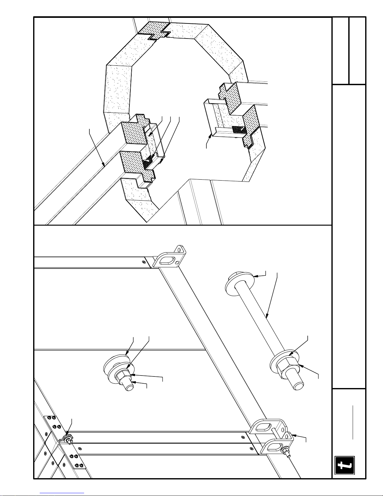
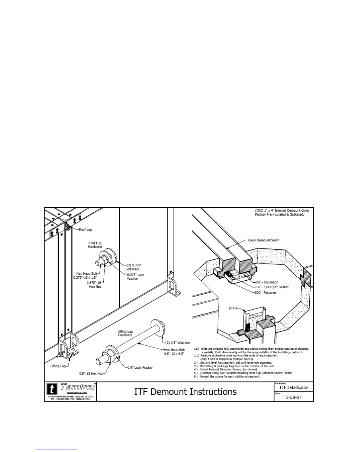
IDC - Insulation
(IDC) 1" x 4" Internal Demount Cover
Factory Pre-insulated & Gasketed.
Caulk Demount Seam
IDC - 1/4"x3/4" Gasket
IDC - Fastener
(IDC)
1a.) Units are shipped fully assembled and sealed unless they exceed maximum shipping
capabilty. Field disassembly will be the responsibility of the installing contractor.
1b.) Remove protective covering from the ends of each segment
(only if unit is shipped in multiple pieces).
2.) Set and level first segment. Set and level next segment.
3.) Bolt lifting & roof lugs together on the exterior of the unit.
4.) Install Internal Demount Covers. (as shown)
5.) (Rooftop Only) See "Weatherproofing Roof Top Demount Seams" detail
6.) Repeat the above for each additional segment.
Roof Lug
Roof Lug
Hardware
(2) 0.375"
(2) 0.5" Washers
Hex Head Bolt
0.5"-13 x 6.5"
ITF Demount Instructions
0.375" Lock
Washer
Washers
Hex Nut
0.375"-16
Hex Head Bolt
0.375"-16 x 1.5"
Hardware
Lifting Lug
0.5" Lock Washer
0.5"-13 Hex Nut
www.temtrol.com
Temtrol
Lifting Lug
PH: (405) 263-7286 FAX: (405) 263-4924
15 EAST OKLAHOMA AVENUE OKARCHE, OK 73762


O-ITF-07
Page 1
P.O. Box 409 • 15 East Oklahoma Avenue • Okarche, OK 73762 • (405) 263-7286
Tem trol, In c.
Manufacturers of ….. Customized Air Handling Units
SERIES ITF OUTDOOR - MOUNTED AIR HANDLING UNITS
Delivery, Storage, Installation,
"Start-up", Maintenance and Inspection Instructions
(A) DELIVERY
(1) Equipment is purchased F.O.B. Factory and is the responsibility of receiving party to inspect unit
upon arrival at the destination before unloading or moving unit to its permanent location; inspect
closely for damage which may have been caused in transit. Report damage to delivering carrier
promptly (list damage or shortage on freight bill if possible). If damage is noted or discrepancies
found, the local Temtrol, Inc. sales representative should be notified immediately so that
corrective action may be instigated. Where local repairs or alterations are required, the
representative should be fully informed by the contractor as to the extent and expected cost of
work required. Unauthorized back-charges will not be recognized by Temtrol, Inc.
(B) STORAGE
(1) Should storage of unit be required caution should be taken to set unit relatively level and in clean
location to protect motor, bearings, coils, filters and etc. from excessive dust. Also avoid storage in
location where children play and/or public access. Air handling units should not be used as on site
storage for other mechanical trades. If units are to be stored for an extended period of time the
following maintenance procedures must be performed:
a. Fan wheels should be rotated by hand every 30 days.
b. Each month bearings should be purged with new grease to remove
condensation.
c. Before start-up new grease must be added to the bearings
d. Belts should be removed, then prior to start-up, inspect and replace if necessary,
reinstall belt.
e. All openings and access doors must remain sealed during storage.
f. Dampers must be cleaned and lubricated prior to start-up.
g. Extended storage could result in condensation on the inside of the unit.
Affected areas should be cleaned and dried prior to start-up.
O-ITF-07
Page 2
(C) INSTALLATION
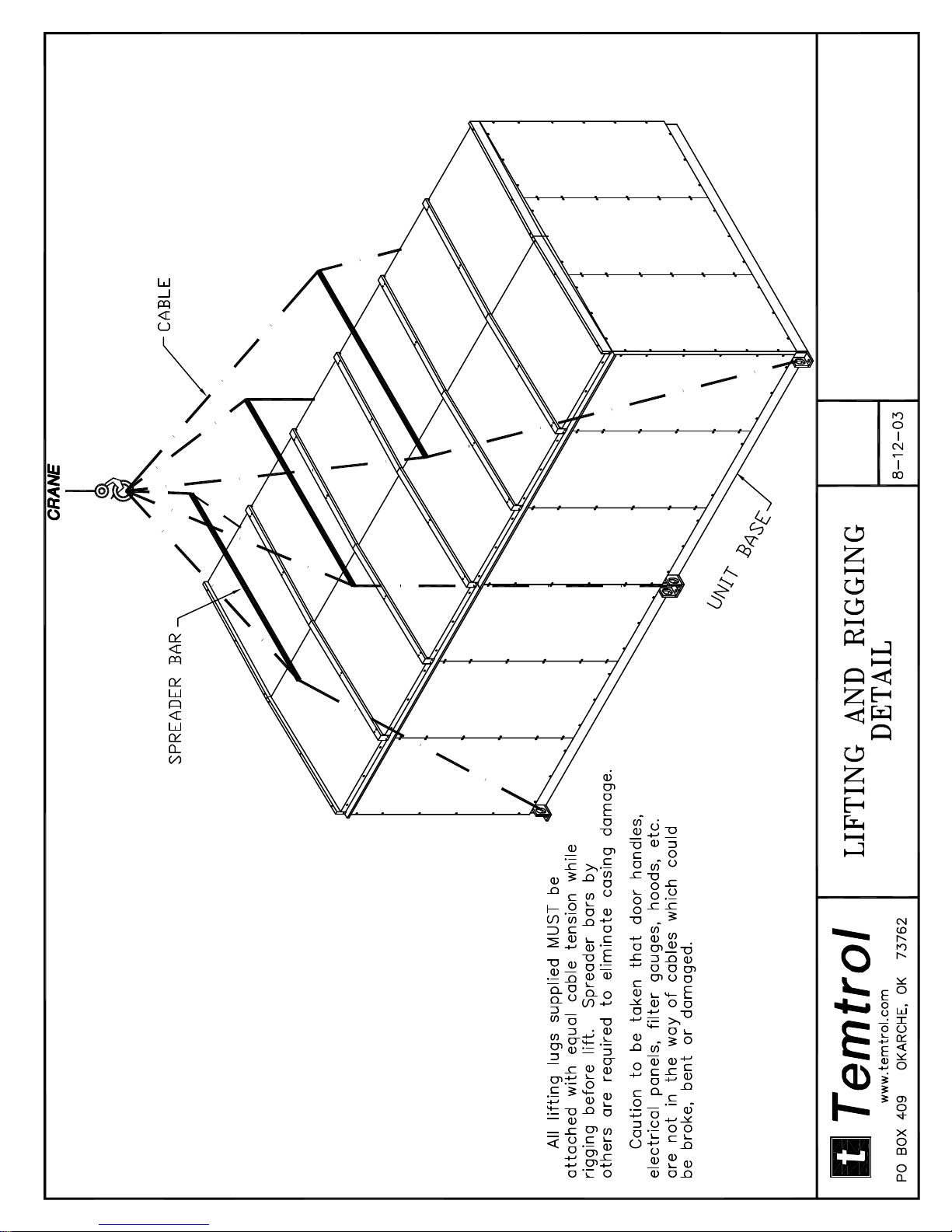
(1) An experienced, reliable rigger should be selected to handle the unloading and final placement of
the equipment. Handle equipment with care during installation to avoid damage due to twisting,
bouncing or tilting. Rigger should be advised that the unit contains delicate components and is
to be handled in upright position only. Avoid excessive stress to fans, shafts, bearings,
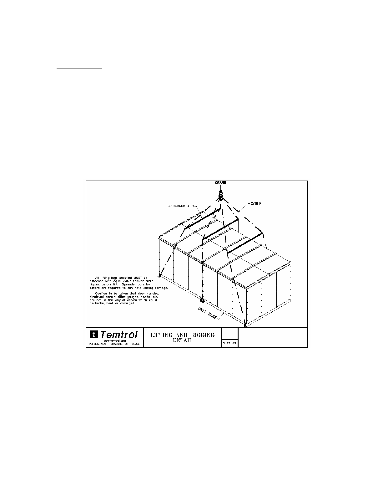
(2) Lifting brackets are provided on the sides of the unit and equal tension of cables at each bracket
is essential for weight distribution and safety. Rigging cables should be as long as the
longest unit piece dimension at corners to prevent stress on assembly.
coil fin and tubes, dampers, isolators, filter accessories, humidifiers, piping, electrical, motors, drives,
access doors and insulation. This will save time and expense during start-up and initial service
warranty period.
Larger Drawing
Located In The
Manual
(3) Roof-curbs (where required) must be installed square and level. Curb should be field welded or
bolted to roof joists or deck field flashing and unit mounting to secure in place. Apply curb
gasket material (furnished with unit) to top of curb before unit mounting. Foundation for curb
must be adequate to support weight of unit without deflection to maintain spirit level of unit after
installation.
O-ITF-07
Page 3
Larger Drawings Located In The Manual
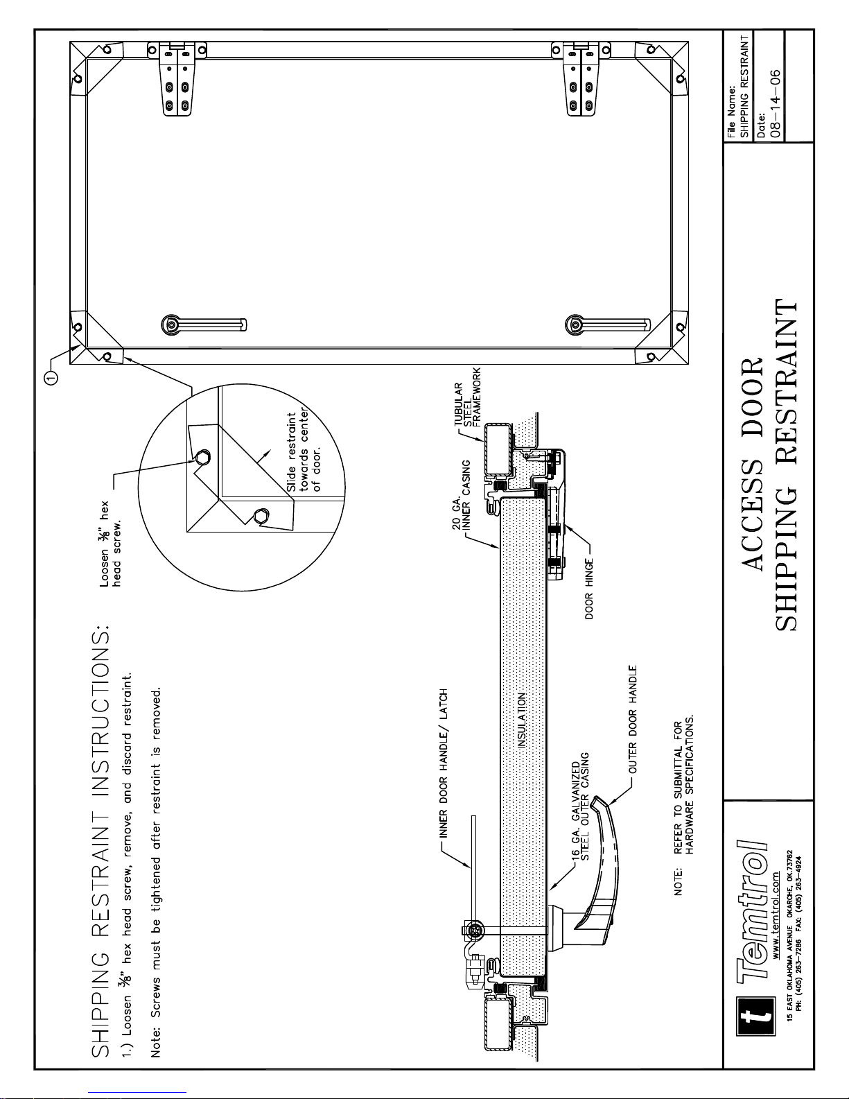
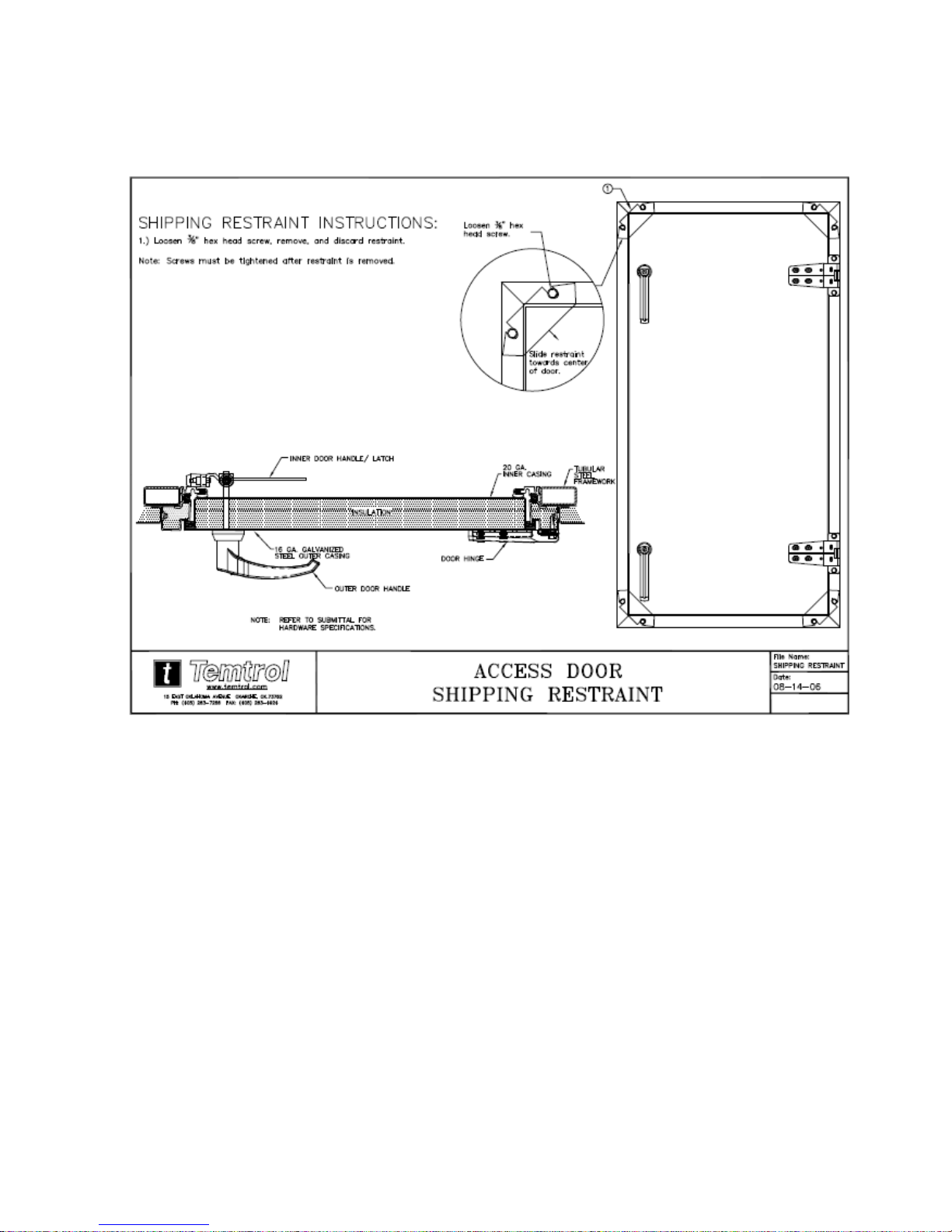
(4) Access Door Shipping Restraint:
a. Loosen 3/8” hex head screws.
b. Slide restraint towards center of door – remove & discard.
c. Retighten hex head screws.
(5) Steam coils are drainable if unit is level. Water coils are also drainable except for special
circuiting. When special circuitry has been furnished coil must be protected from freeze damage
by means of anti-freeze liquids or heaters.
(6) Condensate drain lines inside or to roof from pan must be pitched and include a water seal or
trap to prevent the passage of air into or out of the unit via the drain in the field by the contractor.
Intermediate pans for coils more than one high include downspouts to main pan. A minimum of
2 x (S.P.) trap is required in the condensate line to prevent condensate back up.
O-ITF-07
Page 4
(7) Multi-section units if furnished have (IDC) 1” x 4” internal demount cover factory pre-insulated and
gasketed.
1a. Units are shipped fully assembled and sealed unless they exceed maximum
shipping capability. Field disassembly will be the responsibility of the
installing contractor.
1b. Remove protective covering from the ends of each segment – (only if unit
is shipped in multiple pieces).
2. Set and level first segment. Set and level the next segment.
3. Bolt lifting lugs together on the exterior of the unit using factory furnished
hex head bolt (.05” – 13 x 6.5”), (2) 0.5” washers, .05” hex nut plus 0.5”
lock washer.
4. Bolt roof lugs together on the exterior of the unit using factory furnished
Hex head bolt (0.375” – 16 x 1.5”), (2) 0.375” washers, .0375” – 16 hex
nut plus 0.375” lock washer.
5. Caulk demount seam.
6. Install internal demount covers (IDC)
a. IDC- Insulation
b. IDC ¼” x ¾” gasket.
c. IDC Fastener
7. See “Weatherproofing Roof Top Demount Seams” detail – next page (7a)
8. Repeat the above for each additional segment.
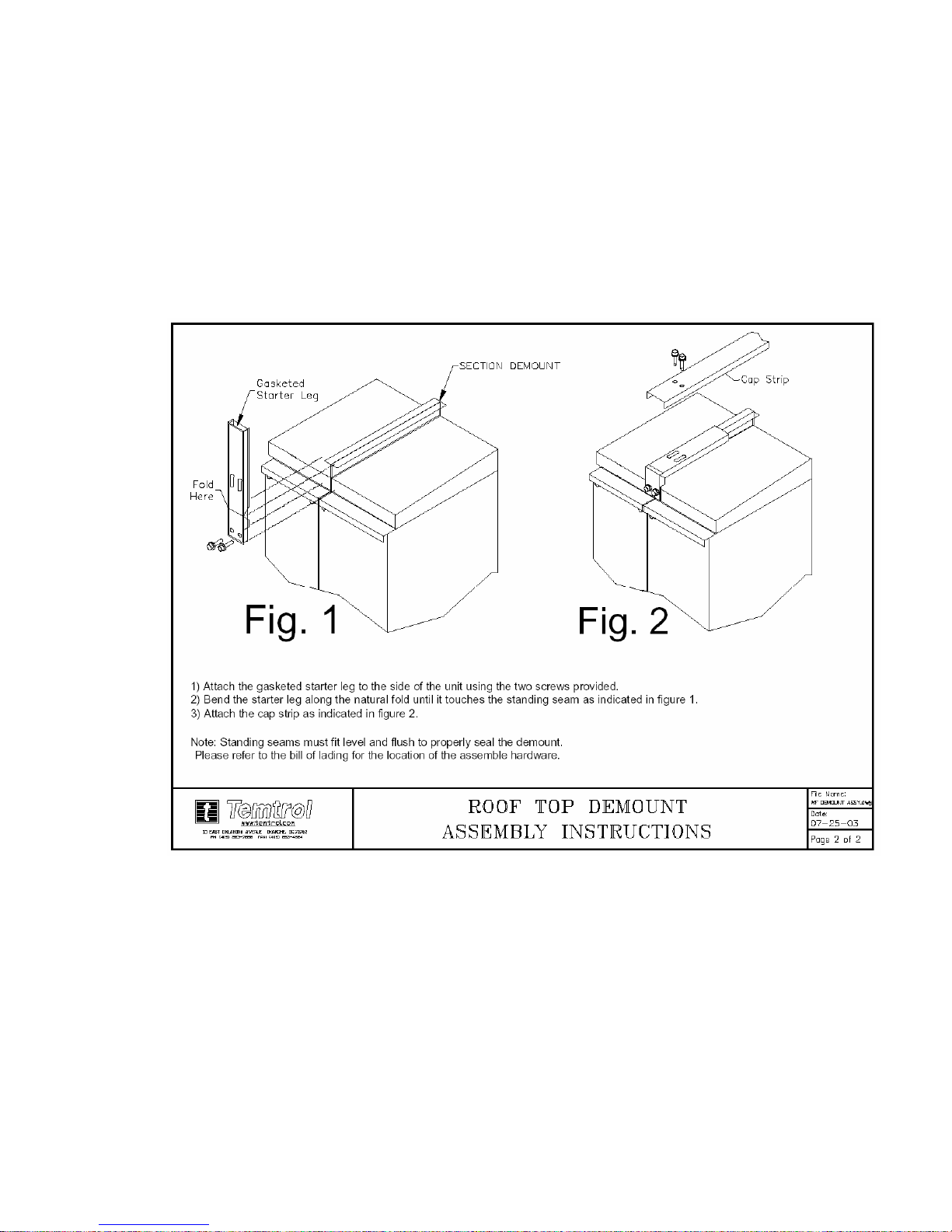
Note: Standing seams must fit level and flush to properly seal the demount
Please refer to the bill of lading for the location of the assemble hardware.
Larger Drawings Located In The Manual
O-ITF-07
Page 5
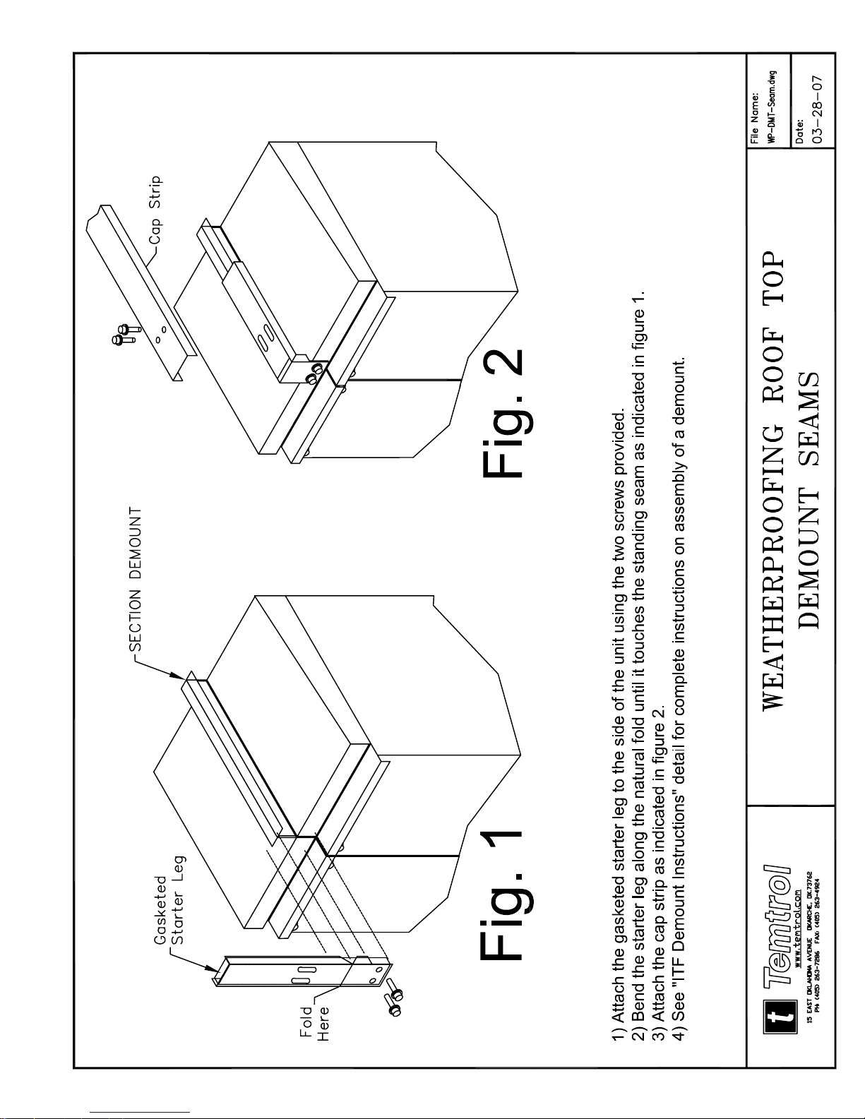
(7a) Weatherproofing roof top demount seams:
1. Attach the gasketed starter leg to the side of the unit using the two screws
provided.
2. Bend the starter leg along the natural fold until it touches the standing seam
as indicated in “Fig. 1.
3. Attach the cap as indicated in “Fig. 2.”
See “ITF Demount Instructions” detail for complete instructions on
assembly of a demount – prior page item (7).
Larger Drawings Located In The Manual

O-ITF-07
Page 6
Larger Drawing
Located In
Manual
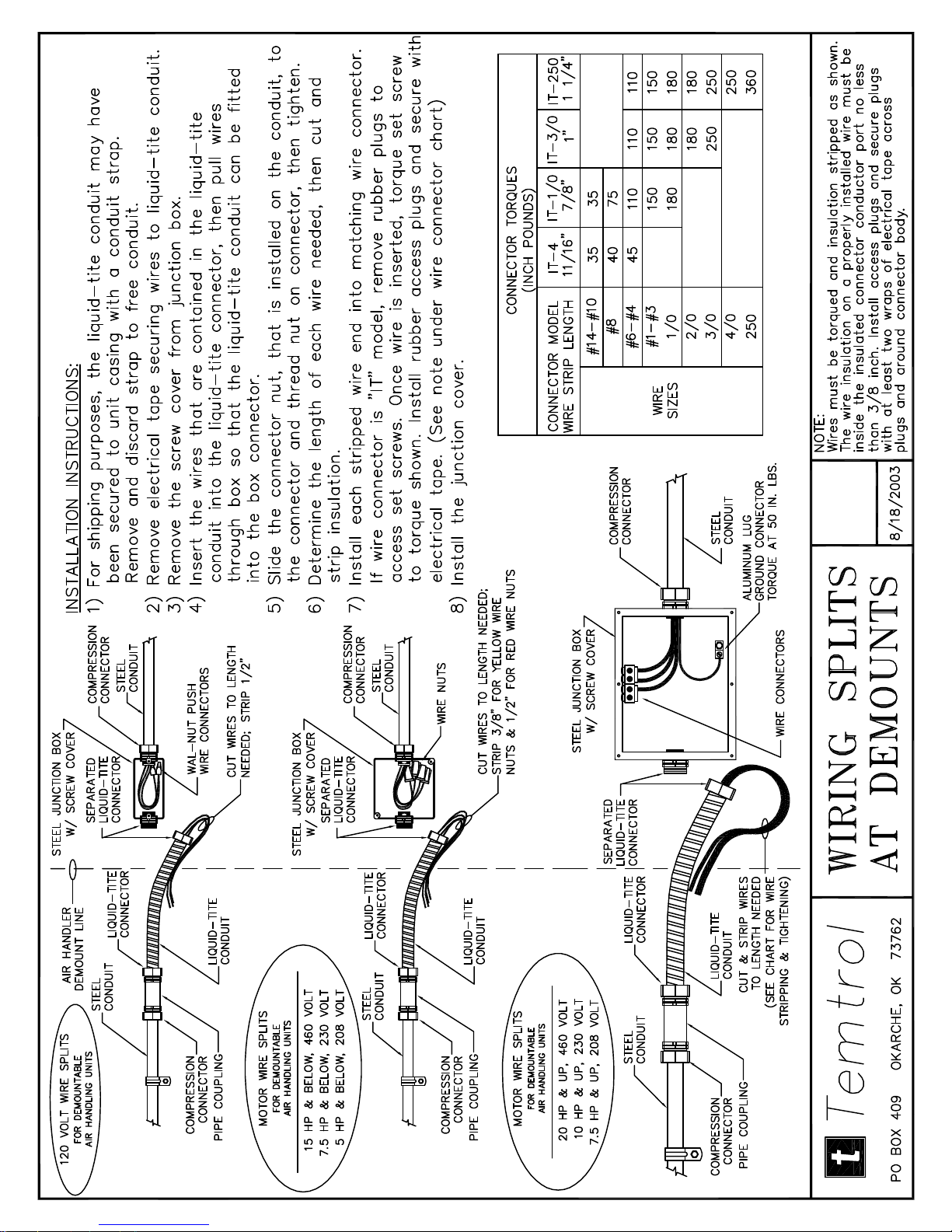
(7b) Wiring Splits at Demounts:
1a. For shipping purposes, the liquid-tite conduit may have been secured to unit
casing with a strap. Remove and discard strap to free conduit.
2a. Remove electrical tape securing wires to liquid-tite conduit.
3a. Remove the screw from junction box.
4a. Insert the wires that are contained in the liquid-tite conduit into the liquid-tite
connector, then pull wire through box so that the liquid-tite conduit can be
fitted into the box connector.
5a. Slide the connector nut, that is installed on the conduit, to the connector and
thread nut on connector, then tighten.
6a. Determine the length of each wire needed, then cut and strip insulation.
7a. Install each stripped wire end into matching wire connector. If wire
connector is “IT” model, remove rubber plugs to access set screws. Once
wire is inserted, torque set screw to torque shown on drawing. Install rubber
access plugs and secure with electrical tape.
Note: Wires must be torqued and insulated stripped as shown.
The wire insulation on a properly installed wire must be
inside the insulated connector conductor port no less than
3/8 inch. Install access plus and secure plus with at least
two wraps of electrical tape across plus and around
connector body.
8a. Install the junction cover.
(8) Observe all pertinent local ordinances and codes covering installation and operation of air
handling equipment. Adequate clearance for the service and removal of components should be
provided (Do Not install unit in a tight space or dangerously close to roof edge especially on
access side).
O-ITF-07
Page 7
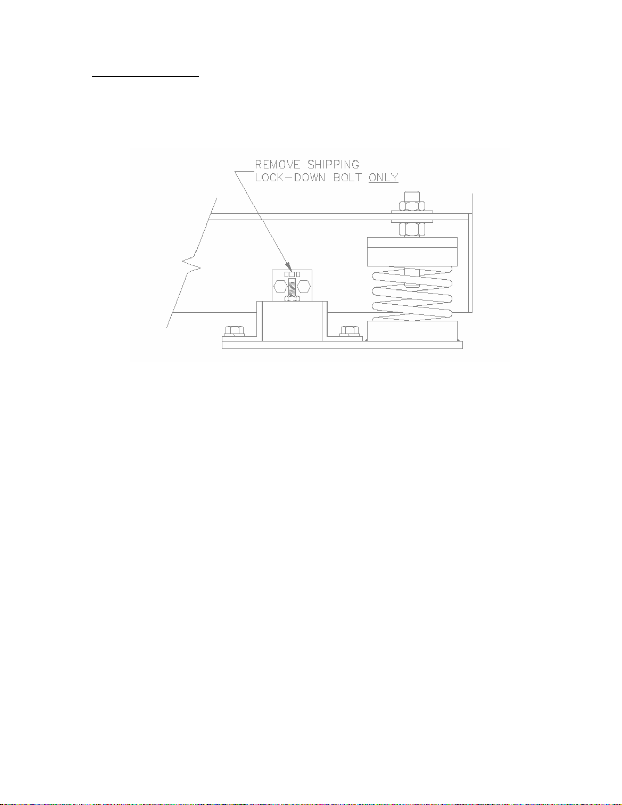
(D) "START-UP" SERVICE
(1) After unit is permanently positioned, fan isolation shipping lock-down bolt, only (see drawing), should
be removed. If load points are not on same plane after supports are removed readjust isolator or shim
until elevation of load points are uniform.
Larger Drawing
Located In The
Manual
(2) Access door to piping compartment is provided if pipe chase is furnished. All plumbing in field
should be done through chase (Do Not puncture casing). Use back-up wrenches on stubouts and
swing joint piping or flex piping to avoid damage to headers and tubes. If, for any reason, it is
necessary to cut a hole in the unit casing, this hole should be cut through a side panel (not
through any access door) and then carefully sealed. If vestibule is furnished all piping should be
run inside the vestibule and plumbed through the chase hole cover plate. Access door to
vestibule or chase compartment should be closed and latched securely to avoid plumbing freeze
up.
(3) Vault type door latches provided on access doors can be adjusted by changing position of bevelled
flange or handle on inside. Access door gasketing must not be removable or leakage of air and
water could result.
(4) Check motor mounting to make sure all nuts are tight. Confirm that the motor voltage, phase,
and HP size are compatible with wiring. Motor nameplate amperage is maximum. All electrical
connections should be tight, complete and properly terminated.
(5) Supply and return air duct flanges are provided and should be attached to ducts with flexible
connector unless fans are internally isolated. Multizone units require field zo ning of individual
zone segments by use of "W" clips which attach to zone separators.
(6) Fan blower wheels should rotate freely. Check motor and fan sheave for proper alignment and
make sure set screws are tight. Check bearing-collar set screws on fan shaft and fan hub set
screws for tightness. Loose collars and/or set screws will ruin the shaft quickly. Ball bearings
have been lubricated at the factory and do not need further attention at start-up. Do Not operate
fans with imbalance. During fan (supply and return) start-up observe the rotation and if fan is
operating backward, reverse two legs of the supply electrical power if three phase.

O-ITF-07
Page 8
(7) Rotate damper (Face & Bypass, Outside Air, Return Air, Exhaust and Zone Dampers) shafts to
test action; rough handling may have caused damper blades to bind. Damper shaft extension
(1/2" shaft) is provided to accept manual or automatic controls. Do Not overdrive damper
motors, this will deform dampers and/or linkage.
(8) Outside air inlet hood and exhaust outlets (if not mounted when shipped) have been predrilled for
attachment in field. After mounting, hoods should be caulked for weatherizing. Both the hood
and the outlets include birdscreen and louvers.
(9) Filters (when furnished by TEMTROL, INC.) are often furnished and mounted in the racks or in
boxes inside the unit. Check to make sure the filter cartridge count is correct. (Filter count is
found on the Data Sheet). If filter count is short, the exact number received should be noted on
the freight bill at the time of delivery. Check to make sure that filter media has been installed
properly in the rails. Check to be sure that the filters called for are used; failure to use the filters
that your TEMTROL, INC. Air Handler has been designed for can cause fan motor overload
and/or cause the coils to become dirty and restrict airflow. Filter access doors should always be
latched firmly to stop air by-pass around filter cartridges.
(10) Check all screws, bolts, nuts, electrical and piping connections for tightness.
(11) If unit heaters are provided check thermostat settings to insure freeze protection.
(12) Supply and return fan drives are provided in the mid-speed adjustment range when variable
speed sheaves are furnished. The motor sheave pitch diameter is field adjustable for the required
air flow. When final adjustments are complete the current draw of the motor should be checked
and compared to full load amperage rating of the motor. After supply fan is set, the return fan
drives should be adjustable for proper pressurization of the building. Sheaves with two or more
grooves should be adjusted by the same number of 1/2 or full turns from closed position to insure
the same pitch diameter so belts bear equal load. DO NOT FORCE BELT OVER THE
GROOVES. Hub type fan sheaves are furnished. Sheaves must be tightened securely before
drive is operated.
(13) Hinged or slide rail motor mounts are furnished with two adjusting bolts. Bolts must be adjusted
equally or so drives maintain proper alignment. Correct belt tension should be acquired by use of
belt tension checker tool. Over tightened belts reduce belt and bearing life substantially, yet belts
must be tight enough to prevent slippage.
(14) Humidifiers if installed include operator, trap, strainer and manifold mounted or furnished and
mounted by contractor. Supply steam connects at top to strainer and return connects at leaving
side of trap. Piping to and from humidifier should not be reduced in size with pitch (of 1/2" in
10') length without sag.
(15) After 24 hours operation re-check "start-up" items.
(16) See Prestart and Operation Check Sheet.

O-ITF-07
Page 9
(E) MAINTENANCE AND INSPECTION SERVICES
(1) FAN - Check blades for dirt and/or grease build-up especially on concave sides. Check set screws
and/or set collars of fan wheel and bearings for tightness. Check bearing mounting bolts and fan
housing cut off blade bolts and nuts for tightness. If fans are furnished with housing drains, see
that "weep holes" in bottom are open. If housing access door is furnished be sure it is properly
sealed and latched. Remove all debris from fan section and unit in general.
(2) BEARINGS AND SHAFT - Ball or Roller bearings are greased at the factory and therefore ready
to run at "start-up"; however routine maintenance and inspection is required there after. Normal
operation of bearings are "cool or warm to touch". High bearing temperature accompanied by
excessive leakage of grease indicates too much grease. High temperature with no grease showing
at the seals, particularly if the bearing seams noisy, indicates too little grease. If running
discloses an excessive amount of grease in the bearings the grease fittings should be removed
until the excess has escaped. Fan shafts should be coated to prevent corrosion yet check
that dirt or debris build-up is not accumulating which could affect balance.
(3) FAN BEARING LUBRICATION - Lubrication intervals vary with the period of operation and
temperature of the air. Do Not Over-Lubricate. The bearing is factory lubricated with Lithium
based grease of NGL1#2 consistency, such as Sinclair Litholene Multipurpose, Avalinia #2,
Texaco Multifax #2, Humble Lidok #2, Mobil Armyac#781 or Phillips Philube L2.
O-ITF-07
Page 10
START – UP REPORT
Temtro l, Inc .
Manufacturers of ….. Customized Air Handling Units
Start – UP Date: ______________________
Job Name: _______________________Unit Serial Number – U ________________
A Start- Up report must be submitted for each unit on the job. For warranty purposes, start – up
occurs when the equipment and/or blowers are started for operation regardless of when the building
may be ready for operation.
GENERAL Initials or 3
1. Inspect the unit for shipping and installation damage.
2. Check Bill of Lading against material received
3. Make sure all packing material has been removed from unit.
4. Inspect unit demounts for proper re-assembly ( if unit shipped in sections )
PRE-START
1. Remove shipping lock down bolts. See drawing on inside Supply Fan access door
2. Check fan wheel set screws for tightness and motor and fan sheave for proper alignment
3. Manually rotate fan wheels and motors to assure freedom of movement
4. Check main supply voltage
5. Check electrical connections for tightness
6. Check main fan amp draw ( Refer to motor nameplate )
7. Check condensate drain traps ( Separate traps are required for each drain connection )
8. Inspect system piping for proper installation
9. Check to see that proper filters are installed
10. Clean inside of unit of all construction dirt and debris
11. Adjust access doors for proper alignment if necessary
P.O. Box 409 • 15 East Oklahoma Avenue • Okarche, OK 73762 • (405) 263-7286 • (405) 263-4924

O-ITF-07
Page 11
OPERATIONAL CHECK
Warning ! Do not operate unit if system is not properly balanced.
1. Check damper operation to assure freedom of movement
2. Momentarily start fan motor and assure correct rotation
3. Check belts for tightness
4. If unit is equipped with variable frequency drive, refer to enclosed manufacturers
recommended start-up procedures.
5. Record motor rpm / amp:
Supply fan # 1 ___________________ rpm Supply Fan # 1 _________________ amps
Supply fan # 2 ___________________ rpm Supply Fan # 2 _________________ amps
Return Fan # 1 __________________ rpm Return Fan # 1 _________________ amps
Return Fan # 2 __________________ rpm Return Fan # 2 _________________ amps
6. Record unit External Static Pressure (esp.) and Total Static Pressure (tsp).
Supply fan # 1 ___________________ esp Supply Fan # 1 _________________ tsp
Supply fan # 2 ___________________ esp Supply Fan # 2 _________________ tsp
Return fan # 1 ___________________ esp Return Fan # 1 _________________ tsp
Return fan # 2 ___________________ esp Return Fan # 2 _________________ tsp
7. Record Unit Supply and Return CFM:
Supply air CFM: ___________________ Return air CFM: ____________________
8. Verify unit is operating at design conditions
9. While unit is in operation verify no excess standing water in drain pan.
P.O. Box 409 • 15 East Oklahoma Avenue • Okarche, OK 73762 • (405) 263-7286 • (405) 263-4924
O-ITF-07
Page 12
Note: After 24 hours of operation re-check set screws on bearing collar and fan hub
for proper tightness.
Ball and Roller Bearing Setscrew Tightening Torque
Dia.
Hex Size Across
Flats
#10 (109) 3/32
Min. Recommended Torque
Valuline
in.lbs ft.lbs
1/4 1/8 22 1.8
5/16 5/32 40 3.3
3/8 3/16 65 5.4
7/16 7/32 130 10.8
1/2 1/4 200 16.7
5/8 5/16 290 24.2
3/4 3/8 470 39.2
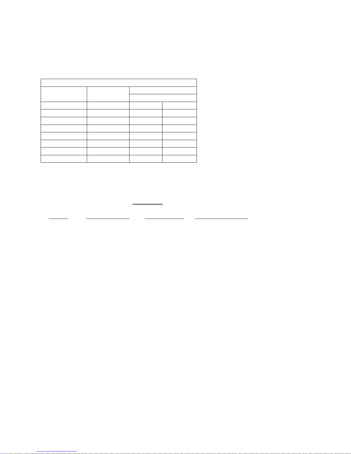
The following table should be used as a relubrication guide:
Conditions
SPEED
TEMPERATURE CLEANLINESS GREASE INTERVAL
100 RPM Up to 120 degrees F Clean 6 to 12 months
500 RPM Up to 150 degrees F Clean 2 to 6 months
1000 RPM Up to 180 degrees F Clean 2 wks to 2 months
1500 RPM Over 210 degrees F Clean Weekly
Any Speed Up to 150 degrees F Dirty Daily to 2 wks
Any Speed Over 150 degrees F Dirty Daily to 2 wks
Any Speed Any Temperature Very Dirty Daily to 2 wks
Any Speed Any Temperature Extreme Cond. Daily to 2 wks
Add grease slowly with shaft rotating, until a slight bead forms at the seals.
Start – Up performed by: ______________________________ Date: ______________
Notes:
______________________________________________________________________________________________
______________________________________________________________________________________________
______________________________________________________________________________________________
______________________________________________________________________________________________
P.O. Box 409 • 15 East Oklahoma Avenue • Okarche, OK 73762 • (405) 263-7286 • (405) 263-4924

O-ITF-07
Page 13
(4) MOTOR AND MOTOR BEARINGS - Check for dirt and debris accumulation on "air travel"
openings of open type motors to prevent overheating. Relubricate motor bearings every 2000
hours of operation while it is warm and at a stand still. Remove and clean upper and lower
grease plugs. Insert grease fittings into upper hole adding a small amount of clean grease with a
low pressure gun. Run motor 5 minutes before replacing plugs. Excessive grease will overheat
the bearings. Use only high grade mineral grease having a 200 degrees F safe operating
temperature. (If special lubrication instructions are shown on the motor nameplate they will
supersede all other instructions).
(5) SHEAVES - After air balance, require no further adjustment. However, sheave locking devices,
wear, alignment and belt tension should be checked on a regular basis.
(6) DAMPER BLADES AND LINKAGE - should be inspected regularly for dirt and/or debris build
up to insure abnormal wear or damage does not occur. Winterize damper system prior to cold
weather to insure that proper sequence of control is being maintained, paying close
attention to operation of outside air intake. Outside air damper should be checked closely for
minimal leakage when closed.
(7) OUTSIDE AIR INTAKE HOOD - should be checked for debris in birdscreen and/or obstructions
to air flow (such as old boxes, new walls or fences, etc.) around unit. Clean or remove as
required.
(8) WATER COILS - (Heating and Cooling) if not antifreeze protected or heater protected should be
drained as thoroughly as possible and then treated in the following manner:
Fill each coil independently with an antifreeze solution
using a small circulating pump and again drain. Check
freezing point of antifreeze before proceeding to next
coil. Due to a small amount of water always remaining in
each coil, there will be a diluting effect. The small
amount of antifreeze solution remaining in coil must
always be concentrated enough to prevent freeze-up.
Carefully read instruction for mixing antifreeze solution
used. Some products will have a higher freezing point in
its natural state than when mixed with water.
Failure of controls, outside air dampers and air stratification can cause freeze-up and permanent
coil damage if above precautions are not observed. Do Not allow dirt to accumulate between the
fins of coils. Use water, steam or air to remove dirt.
(9) STEAM COIL - fins should be cleaned in the same manner as Water Coils. Steam lines to and
from unit should be checked for pitch, pipe sag and blockage to avoid "Water-hammer".
Strainers and traps require annual cleaning minimum.
(10) CONDENSATE PAN - should be checked for dirt and debris build-up and cleaned. Trap and
drain should also be cleaned especially if blockage is evident.
O-ITF-07
Page 14
(11) FILTER ASSEMBLY - tracks should be checked for rail seal retention where required and all rails
should be cleaned annually to control dirt build-up, filter drag and dust by-pass during change
out of media. Dirty filters reduce the air volume handled by the unit, and thereby its capacity.
Unit should not be run without proper filters or fan motor overload, dirty coil and restricted air
flow will result. Proper media retainers should be used at all times to avoid possible media
"blow-out", which can cause blockage of air flow and/or damage rotating fan and motor parts.
Do not operate media beyond its rated capacities before change out or "blow-out" damage
can result.
(12) CASING AND ACCESS DOORS - should be checked for leakage (air and/or water). Door gasket
must be in proper alignment and if damaged, should be replaced. Inside access panels must be
latched properly to avoid air recirculation.
Larger Drawing
Located In The
Manual
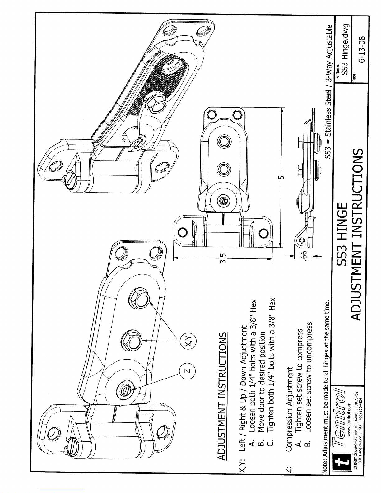
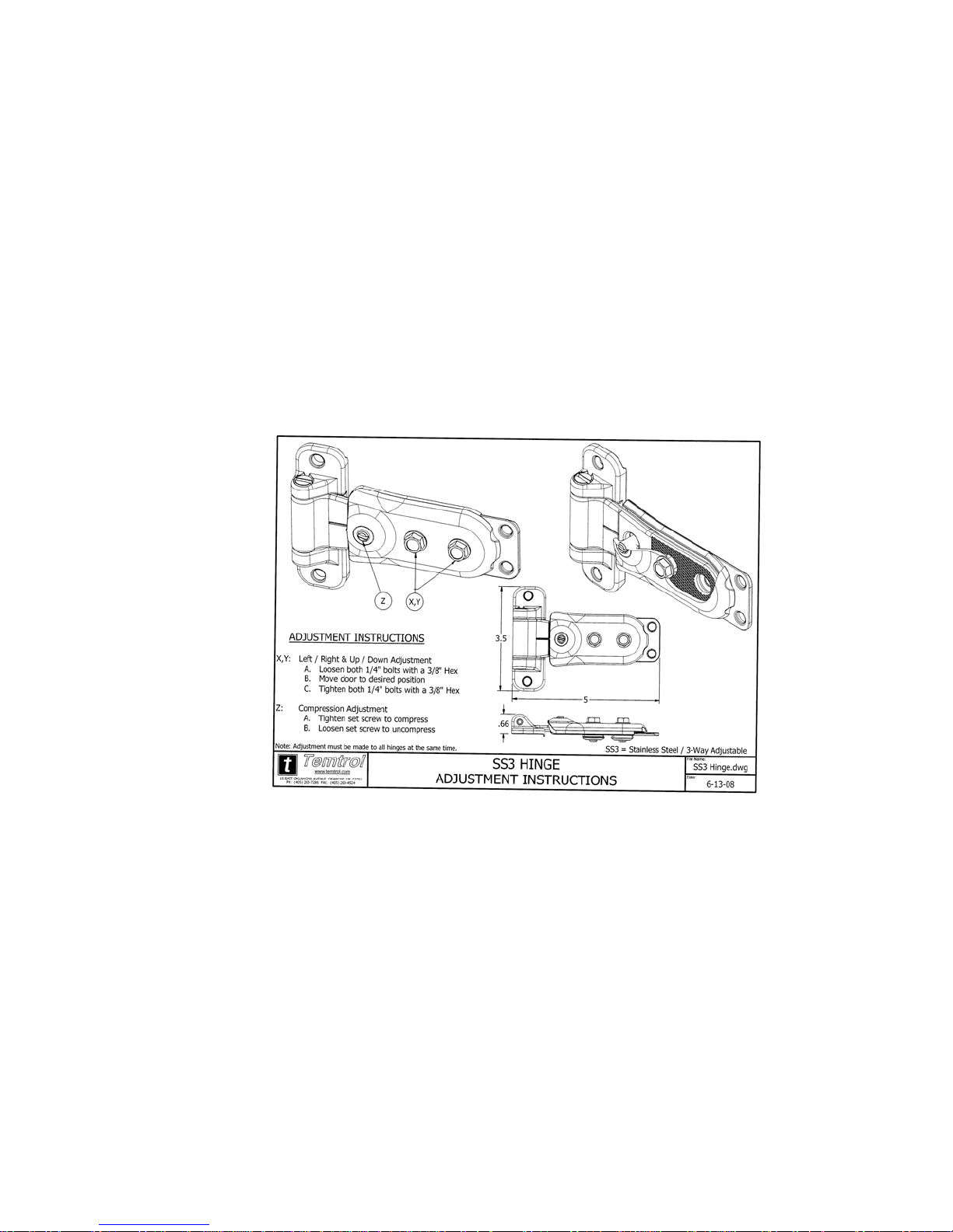
Door Adjustment: (All adjustments must be made to all hinges at the same time)
X,Y: Left/Right and Up/Down adjustment;
A. Loosen both 1/4” bolts with a 3/8” hex.
B. Move door to desired position.
C. Tighten both 1/4” bolts with a 3/8” hex.
Z: Compression Adjustment;
A. Tighten set screw to compress.
B. Loosen set screw to uncompress.

O-ITF-07
Page 15
(13) COILS - can be removed from unit through either end of unit. After removing piping and end
panels, remove bolts holding coil to structural frame at the air entering side of coil. The coil and
casing can then be pulled out.
(14) WIRING AND COMPONENTS - should be made and remain in accordance with National, State
and local codes that apply to this equipment. Check connections of wiring and retighten so
danger of a poor connection causing overheating and component failure through inadequate
current handling can be avoided. Good practice and safety indicates that before attempting
service to components, de-energize the systems and only after workers are clear of rotating and
electrical devices can unit be energized again.
(15) ULTRAVIOLET (UV) GERMICIDAL IRRADIATION LIGHTS – The United States Environmental
Protection Agency (EPA) believes that molds and bacteria inside buildings have potential to cause
health problems in sensitive individuals
as a factory-engineered and installed option in select commercial air handling products.
When UV lights are factory provided, polymer materials that are susceptible to deterioration by the
UV-C light will be substituted or shielded from direct exposure to the light. In addition, UVCradiation can damage human tissue, namely eyes and skin. To reduce the potential for inadvertent
exposure to the lights by operating and maintenance personnel, electrical interlocks that automatically
disconnect power to the lights are provided at all unit entry points to equipment where lights are
located.
Moisture and your Home; Brochure EPA 402-K-02-003.
1. United States Environmental Protection Agency: A Brief Guide to Mold,
WARNING
!
Equipment Damage, And Personal Safety Risk, From Ultraviolet (UV) Lights!
Temtrol does not recommend field installation of ultraviolet lights in its air handling
equipment for the intended purpose of improving indoor air quality. High intensity
C-band ultraviolet light known to severely damage polymer (plastic) materials and
poses a personal safety risk to anyone exposed to the light without proper personal
protective equipment (can cause damage to eyes and skin). Polymer materials
commonly found in HVAC equipment that may be susceptible include insulation on
electrical wiring, fan belts, thermal insulation, various fasteners and bushings.
Degradation of these materials can result in serious damage to the equipment.
Temtrol accepts no responsibility for the performance or operation of our air
handling equipment in which ultraviolet devices were in stalled outside of the
Temtrol factory.
(16) AIR FILTER GAUGE - "pick-ups" should point against air flow for best results without
restriction. Oil Manometers require split to operate properly (check zero set).
(17) HUMIDIFIER - strainer screen in supply line should be cleaned a few days after put in operation
and thereafter at least once a season - more often if much dirt is found in the screen. The trap
should be inspected at the same time strainer is cleaned.
(18) UNIT HEATER OR ELECTRIC COIL - should be checked for dirt on resisters and removed by
use of air only. DO NOT attempt cleaning without positive shut down.
(1)
. If specified, Temtrol provides ultraviolet lights (UV-C)

O-ITF-07
Page 16
(19) PNEUMATIC OPERATORS - and linkage should be inspected for sequence and travel and
vacuum hose leaks especially prior to cold weather usage where furnished.
(20) OTHER COMPONENTS - not mentioned should be maintained per instructions attached to
component.
(21) REPLACEMENT PART - (if required) orders for service or replacement must include serial
number, model number and unit tag of unit as stamped on serial plate, attached to unit. If
replacement parts are required, state date of installation of unit, date of start-up and date of
failure, along with an explanation of the malfunction and a description of the replacement parts
required. Goods may not be returned except by permission of authorized factory officials of
TEMTROL, INC. at Okarche, Oklahoma and when so returned will be subject to a handling
charge and transportation charges prepaid. Following our personal inspection of the returned
part and if it is determined that the failure is due to faulty material or workmanship, credit will
be issued on customer's purchase order if warranty is still in effect.

O-ITF-07
Page 17
ROOF - MOUNTED
O-ITF-07
CABINET
Panels OITF-0001
Insulation OITF-0002
Neoprene gasketing OITF-0003
Metal flange seal OITF-0004
Lifting lugs OITF-0005
Weatherproof screws OITF-0006
Roof-curb OITF-0007
Curb gasketing OITF-0008
Drain Pan with drain OITF-0009
Pan insulation board OITF-0010
FAN (S/A = Supply Air or R/A = Return Air)
Housing OITF-0101
Cutoff OITF-0102
Inlet funnels OITF-0103
Wheel OITF-0104
Shaft OITF-0105
Bearings OITF-0106
Inlet Vanes OITF-0107
Inlet Vane Linkage OITF-0108
Inlet Screen OITF-0109
Flex Connection OITF-0110
Isolators OITF-0111
Discharge diffuser OITF-0112
Sheave and Bushing OITF-0113
Lubrication fittings OITF-0114
(S/A or R/A) OITF-0201
MOTOR
Horse Power w/ voltage, phase RPM OITF-0202
Mount OITF-0203
Sheave and Bushing OITF-0204
Belts - size and length OITF-0205
Belt guard OITF-0206
DAMPER
Face damper OITF-0301
By-pass damper OITF-0302
Face and ByPass combination OITF-0303
Return air damper OITF-0304
Outside air damper OITF-0305
Relief - exhaust damper OITF-0306
Fan discharge damper OITF-0307
Recirculation damper OITF-0308
Min. outside air damper OITF-0309
Manual quadrant OITF-0310
Interconnecting linkage OITF-0311
Fire damper w/"fuse link" OITF-0312
Operator OITF-0313
COIL
Pre-Cooling OITF-0401
Cooling OITF-0402
Preheat OITF-0403
Heating OITF-0404
Reheat OITF-0405
Balance orifice OITF-0406
Connection grommets OITF-0407
Distributor w/nozzle OITF-0408
Hot gas side-port OITF-0409
Expansion valve OITF-0410
Vent and drain plugs OITF-0411
Top and/or bottom casings OITF-0412
Electric heating OITF-0413
COIL SYSTEMS (Special)
Integral Face & By-pass Heating OITF-0501
Reclaim wheel OITF-0502
Reclaim gas-type OITF-0503
Reclaim fluid run-around type OITF-0504
HUMIDIFIER
Humidifier (Steam) OITF-0601
Water spray OITF-0602
Humidifier pan w/drain OITF-0603
FILTER RACKS
Prefilter OITF-0701
2nd filter OITF-0702
Final filter OITF-0703
Exhaust filter OITF-0704
Roll type OITF-0705
Charcoal type OITF-0706
Retainer frames & clips OITF-0707
Gauges OITF-0708
FILTER MEDIA
Prefilter cartridges OITF-0801
2nd filter cartridges OITF-0802
Final cartridges OITF-0803
Exhaust filter cartridges OITF-0804
Roll media OITF-0805
Charcoal Media or tray OITF-0806
ELECTRICAL
Light fixture OITF-0901
Disconnect(Main or service) OITF-0902
Starter (S/A or R/A) OITF-0903
Panel box OITF-0904
Transformer OITF-0905
Terminal strip OITF-0906
Fuse block OITF-0907
Fuses OITF-0908
Unit heater OITF-0909
ACCESS
Door OITF-1001
Door hinge OITF-1002
Door latch OITF-1003
Drip gutter OITF-1004
Door gasket OITF-1005
Window pane WP-001
FINISH
Internal coating OITF-1101
Pan Mastic OITF-1102
Touch-up paint (external) OITF-1103
Not all listed parts apply to each unit.
Prices on application and as effective on date of shipment.
Many parts are available on open market
.
WHEN ORDERING PARTS the following information
must be given:
Unit Serial Number
Unit Model Number
Part Name + Location
Code Number + Place Number
EXAMPLE:
Job Symbol AH-1 AH-2 AH-3
Model No. ITF-RD20 ITF-RDV11 ITF-RBR15
Serial No. U100168-001 U100167-002 U100168-003
Serial No: = U100168-_______
Model = ITF-RDH11
Fan sheave and bushing - S/A (Supply Air Fan) RZR-OITF-0113
Temtrol, Inc.

RT-0 & M79
Page 18
Temtrol, Inc.
INFORMATION COVERING:
AIR HANDLERS
ROOF - MOUNTED
O-ITF-07
PARTS LIST
JOB SYMBOL :
MODEL NUMBER :
DRAWING NUMBER:
SERIAL NUMBER :
PART NUMBER :
JOB SYMBOL :
MODEL NUMBER :
DRAWING NUMBER:
SERIAL NUMBER :
PART NUMBER :
Temtrol, Inc.
Manufacturers of Air Conditioning, Heating Ventilation and Heat Transfer Products
Okarche, OK

MAINTENANCE
FREQUENCY SCHEDULE
Recommended Maintenance Service for Temtrol Equipment
Type of Service Start-Up Monthly Every 6 Months Shutdown Annually
Inspect General Condition of Unit XX
Clean Debris From Unit XX X
Check and Adjust Fan Belt Tension XX
Check Unit for Unusual Noise or Vibration XX
Check Fan Bearing Locking Collars XX
Check Motor Voltage and Current XX
Lubricate Fan Shaft Bearings X See Below X
Lubricate Motor Base Adjusting Screws XXX
Check Fan for Rotation Without Obstruction X
Check Fan for Proper Rotation X
Inspect Protective Finish X
Replace Filters X
Lubricate Damper Linkage X
Check Fans for Unusual Vibration XX
Clean Outside of Coils XX
IMPORTANT SAFETY NOTES
Before performing any maintenance or inspection, make certain that all power has been
disconnected.
Adequate precautions should be taken to safeguard the equipment and the premises from
damage, also the public from possible injury as appropriate for the installation of these
products.
The following table should be used as a relubrication guide:
Conditions
SPEED TEMPERATURE CLEANLINESS
100 RPM Up to 120 degrees F Clean
500 RPM Up to 150 degrees F Clean
1000 RPM Up to 180 degrees F Clean
1500 RPM Over 210 degrees F Clean
Any Speed Up to 150 degrees F Dirty
Any Speed Over 150 degrees F Dirty
Any Speed Any Temperature Very Dirty
Any Speed Any Temperature Extreme Cond.
GREASE INTERVAL
6 to 12 months
2 to 6 months
2 wks to 2 months
Weekly
Daily to 2 wks
Daily to 2 wks
Daily to 2 wks
Daily to 2 wks
Add grease slowly with shaft rotating, until a slight bead forms at the seals.

Temtrol, Inc.
Phone - 405-263-7286 Fax - 405-263-4924
Trouble
Shooting

TROUBLE SHOOTING GUIDES
FANS
PROBLEM PROBABLE CAUSE
Noise Impeller hitting inlet ring a. Impeller not centered in inlet ring.
b. Inlet ring damaged
c. Crooked or damaged impeller
d. Shaft loose in bearing
e. Impeller loose on shaft
f. Bearing loose in bearing support
Impeller hitting cutoff a. Cutoff not secure in housing
b. Cutoff damaged
c. Cutoff improperly positioned.
Drive a. Sheave not tight on shaft (motor and/or fan)
b. Belts too loose. Adjust for belt stretching after
48 hours of operation.
c. Belts too tight.
d. Variable pitch sheaves not adjusted so each
groove has same pitch dia. (multi-belt drives).
e. Misaligned sheaves
f. Belts worn
g. Isolation base shipping restraints not removed.
h. Belts oily or dirty
SOLUTION
Bearing a. Defective bearing
Shaft Seal Squeal a. Need lubrication
Impeller a. Loose on shaft
Noise (Continued) d. Worn as result of abrasive or corrosive
b. Needs Lubrication
c. Loose on bearing supports
d. Loose on shaft
e. Seals misaligned
f. Foreign material inside bearing
g. Worn bearing
h. Fretting corrosion between inner race and shaft.
b. Misaligned
b. Defective Impeller
Do not run fan - Contact manufacturer.
c. Unbalanced

TROUBLE SHOOTING GUIDES
FANS
PROBLEM PROBABLE CAUSE
Housing a. Foreign material in housing
Electrical a. AC hum in motor or relay
High Air Velocity a. Duct work too small for application.
Pulsation or Surge a. Restricted system causes fan to operate at poor
SOLUTION
material moving through flow passage
b. Cutoff or other part loose (rattling during operation)
b. Starting relay chatter
c. Noisy motor bearings
d. Single phasing a 3 phase motor
b. Fan selection too small for application.
c. Registers or grilles too small for
application.
d. Heating or cooling coil with insufficient
face area for application.
point of rating.
b. Fan too large for application
c. Ducts vibrate at same frequency as fan pulsations.
Rattles and/or Rumbles a. Vibrating duct work
b. Vibrating cabinet parts
c. Vibrating parts not isolated from building.
CFM Low - Insufficient Fan a. Mecanical volume control device is improperly set.
Air Flow b. Fan running backwards
c. Cutoff missing or improperly installed.
d. Dirty fan blades.
e. Loose or slipping belts
f. Fan speed too slow
Duct System a. Actual system is more restrictive (more resistant to flow)
b. Dampers closed
c. Registers closed
d. Leaks in supply ducts
e. Insulating duct liner loose.
CFM Low - Insufficient Filters a. Dirty or clogged
Air Flow (continued)

TROUBLE SHOOTING GUIDES
FANS
PROBLEM PROBABLE CAUSE
Coils a. Dirty or clogged
Obstructed Fan Inlets a. Elbows, cabinet walls or other obstructions restrict
No Straight Duct at Fan Outlet a. Fans which are normally used in duct system are
Obstructions in High Velocity a. Obstruction near fan outlet
Air Stream b. Sharp elbows near fan outlet
SOLUTION
air flow. Inlet obstructions cause more restrictive
systems but do not cause increased negative
pressure readings near the fan inlet(s). Fan speed
may be increased to counteract the effect of
restricted fan inlet(s)
tested with a length of straight duct at fan outlet. If
there is no straight duct at the fan outlet, decreased
performance will result. If it is not practical to
install a straight section of duct at the fan outlet,
the fan speed may be increased to overcome
this pressure loss.
c. Improperly designed turning vanes
d. Projections, dampers or other obstructions in part
of system where air velocity is high
CFM High - Too Much System a. Oversized duct work
Air Flow b. Access door open
Fan a. Fan speed too fast
Incorrect Static Pressure System, Fan or Interpretation General Discussion:
of Measurements The velocity pressure at any point of measurement
Incorrect Static Pressure In most systems, pressure measurements are indicators
- Continue - of how the installation is operating. These
c. Registers or grilles not installed
d. Damper set to by-pass coils
e. Filter(s) none in place
f. System resistance much lower than anticipated
is function of the velocity of the air or gas and its density
The static pressure measured in a "loose" or oversized
system will be less than the static pressure in a
"tight" or undersized system for the same air flow rate
measurements are the result of air flow and as such are

TROUBLE SHOOTING GUIDES
FANS
PROBLEM PROBABLE CAUSE
useful indicators in defining system characteristics
Field static pressure measurements rarely correspond
with laboratory static pressure measurements unless
the fan inlet and fan outlet conditions of the installation
are exactly the same as the inlet and outlet conditions
in the laboratory
Static Pressure Low, System System has less resistance to flow than expected
CFM High This is a common occurrence. Fan speed may be
reduced to obtain desired flow rate. This will reduce
HP (operating cost).
Fan a. Backward inclined impeller installed backwards. HP
will be high
b. Fan speed too high
Static Pressure Low, System a. Fan inlet and/or outlet conditions not same as tested.
CFM Low
SOLUTION
Static Pressure High System a. Obstruction in system
CFM Low b. Dirty filters
c. Dirty coils
d. System too restricted
HP High Fan a. Backward inclined impeller installed backwards
b. Fan speed too high
c. Too low system resistance for forward curved fan
System a. Oversized duct work
b. Face and by-pass dampers oriented so coil dampers
are open at same time by-pass dampers are open
c. Filter(s) - left out
d. Access door open
Fan Selection a. Fan not operating at efficient point of rating. Fan size
or type may not be best for application
Fan Does Not Operate Electrical or Mechanical a. Blown fuses
b. Broken belts
c. Loose pulleys
d. Electricity turned off

TROUBLE SHOOTING GUIDES
FANS
PROBLEM PROBABLE CAUSE
SOLUTION
e. Impeller touching scroll
f. Wrong voltage
g. Motor too small and overload protector has broken
circuit
h. Optional thermostats, firestats, freezestats may
lockout fan operation if set incorrectly

TROUBLE SHOOTING GUIDES
ELECTRIC HEATING COILS
PROBLEM PROBABLE CAUSE
Electric Heater Electrical or Mechanical Disconnect switch or main circuit breaker may be
Not Operating in the "OFF" position. If heater has built-in disconnect
switch, door must be closed and switch turned "ON"
before heater will operate
If the fan and heater are interlocked with a fan relay, the
fan must be on before the heater will operate. If an air
flow switch is used, air pressure in the duct must be
sufficient (at least 0.7" W.C.) to close the switch
before the heater will operate
Automatic (or manual) reset thermal cutout may have
opened when overheating resulted from insufficient air
flow or poor air distribution. Allow heater temperature
to return to normal so that automatic thermal cutout
may reset or manual reset thermal cutout may be reset.
Correct cause of overheating before proceeding.
Heat limiter(s) may have opened if local "hot spot"
developed or if automatic reset thermal cutout failed to
open first, when overheating occurred. Correct cause
of overheating and replace heat limiter.
Check main fuses, if open, correct cause of failure
before replacing fuses.
SOLUTION
Electric Heater Cycles Electrical or Mechanical Check air inlet and discharge openings for obstructions.
(Will Not Stay On) See that filters are not clogged, fire dampers are open
and air system is balanced
Check to see that the heater terminal box is tight
against duct and heater safety devices are receiving
sufficient air flow. Air flow must be distributed evenly
over entire face area.
Look at heater coils in operation (through observation
port in duct); any red area is not receiving enough air.
(A small amount of redness is permissible inside the coil
insulation bushings). Make sure that air flow through
every part of the heater is sufficient.
Coils must not glow.
If air flow switch is used, contactors may "chatter" if air
flow is not sufficient to keep switch fully on.
If duct has internal insulation, the insulation may be
blocking the safety devices.
Improper Temperature Electrical or Mechanical Make sure associated control equipment, such as

TROUBLE SHOOTING GUIDES
ELECTRIC HEATING COILS
PROBLEM PROBABLE CAUSE
Regulation thermostats, are in the correct location and that
all controls are adjusted according to manufacturer's
specifications for existing field conditions.
Check air system balance to see that correct amount
of air flow is supplied for proper zone control.
Automatic thermal cutout may be opening (cycling)
before room thermostat is satisfied. (see "Electric
Heater Cycles". Insufficient heat may be caused by:
1. Open heat limiter(s) or thermal cutout
2. Incorrect supply voltage
3. Heater too small (in wattage) for application
SOLUTION

4. Faulty or dirty thermocouple
4. Defective motor or capacitor
TROUBLE SHOOTING GUIDES
Gas Furnace by Reznor
PROBLEM PROBABLE CAUSE
Pilot Will Not Light 1. Manual valve turned off 1 Open valve
(Match Lit System) 2. Air in gas line 2 Disconnect pilot line at shut off bleed air from gas
supply line
3. Incorrect lighting procedure 3 Follow instructions on cover of junction box.
4. Dirt in pilot orifice 4 Remove orifice. Clean with compressed air or solvent
(do not ream)
5. Extremely high or low gas 5 Check line pressure, this should be 3 oz or 5 in. water
pressure pressure minimum. 8 oz or 14 in. maximum
6. Bent or kinked pilot tubing 6 Replace tubing
Pilot Lighted But Magnetic 1. Power not turned on or 1 Turn on power, check fuses, turn on thermostat
Gas Valve Will Not Open thermostat not calling for
(All Manual Valves Are heat.
Open) (Match Lit System) 2. Circuit to magnetic valve 2 Check wiring and connections at transformer and
open thermostat
3. Faulty transformer 3 Replace transformer
4 Clean and test with millivolt meter or test kit. Replace
or safety pilot switch defective part.
5. Faulty thermostat 5 Replace thermostat
6. Faulty magnetic valve 6 Replace valve or magnetic head
7. High gas pressure 7 Max. gas pressure 8 oz or 14" W.C.
SOLUTION
Venter Motor Will Not 1. No power to unit 1 Turn on power, check supply fuses or circuit breaker
Start (RPV Models) 2. No 24 volt power to venter 2 Turn up thermostat, check control transformer output
relay Check for loose or improper wire connections
3. Venter relay defective 3 Replace
4 Replace motor or capacitor
Pilot Will Not Light 1. Manual valve not open 1 Open manual valve
(Spark Ignition System) 2. Air in gas line 2 Bleed gas line
(Venter Operation on RPV 3. Dirt in Pilot Orifice 3 Remove and clean with air pressure
Models) 4. Gas pressure too high or 4 Set supply pressure at 5" to 8" for natural gas - 11"
too low for propane
5. Kinked pilot tubing 5 Replace tubing
6. Pilot valve does not open 6 If 24V available at valve, replace valve
7. No Spark: 7
a. Loose wire connection a. Be certain all wire connections are solid
b. Transformer failure b. Be certain 24 volts is available
c. Incorrect spark gap. c. Maintain spark gap 7/64"
Pilot Will Not Light Con't d. Spark cable shorted to d. Replace worn or grounded spark cable

TROUBLE SHOOTING GUIDES
Gas Furnace by Reznor
PROBLEM PROBABLE CAUSE
(Spark Ignition System) ground
(Venter Operation on RPV e. Spark electrode shorted e. Replace pilot if ceramic spark electrode is cracked
Models) to ground or grounded
f. Drafts affecting pilot f. Make sure panels are in place and tightly secured
to prevent improper or unusual drafts at pilot
g. G60 control box not g. Make certain G60 is grounded to furnace chassis
grounded
h. Faulty G60 h. If 24V is available to G60 controller and all other
causes have been eliminated, replace G60
8. Optional lockout device 8 Reset lockout by interrupting control circuit at
interrupting control circuit thermostat
by above causes
9. Faulty combustion air 9 Replace combustion air proving switch
proving switch
Pilot Lights, Main Valve 1. Manual valve not open. 1 Open manual valve
Will Not Open 2. Main valve not operating 2
(Spark Ignition System) a. Defective valve a. Replace if 24V is measured at valve connection
and valve remains closed
b. Loose wire connection b. Check and tighten all wiring connection
3. G60 does not power main 3
valve
a. Loose wire connection a. Check and tighten all wiring connection
b. Flame sensor grounded b. Be certain flame sensor lead is not grounded or
(Pilot lights - spark insulation or ceramic is not cracked. Replace as
continues) required.
c. Gas pressure incorrect c. Set supply pressure at 5" to 8" for natural gas - 11"
for propane
d. Cracked ceramic at d. Replace sensor
sensor
e. Faulty G60 e. If all checks indicate no other cause replace G60
DO NOT ATTEMPT TO REPAIR G60 THERE ARE
NO FIELD REPLACEMENT COMPONENTS
CONTAINED IN THIS DEVICE.
SOLUTION
No Heat 1. Dirty Filters 1 Clean or replace filters

TROUBLE SHOOTING GUIDES
Gas Furnace by Reznor
PROBLEM PROBABLE CAUSE
(Heater Operating) 2. Incorrect manifold pressure 2 Check manifold pressure
or orifices
3. Cycling on limit control 3 Check air throughput
4. Improper thermostat or 4 See thermostat instructions
adjustment
5. Belt slipping on blower 5 Adjust belt tension
Cold Air is Delivered on 1. Fan control heater element 1 Connect as per wiring diagram inside junction box
Start-Up, During improperly wired cover
Operation 2. Defective fan control 2 Replace fan control
3. Incorrect manifold pressure 3 Check manifold and line pressure
Motor Will Not Run 1. Circuit open 1 Check wiring and connections
2. Fan control inoperative 2 Replace fan control
3. Contactor inoperative 3 Replace contactor
4. Defective motor 4 Replace motor
SOLUTION

TROUBLE SHOOTING GUIDES
HEATING COILS
PROBLEM PROBABLE CAUSE
Coil Does Not Operate Steam valve failure a. Check steam valve. If air operated, check proper air
(Steam Coil) pressure. If electrically operated check for no power or
loose connection. If manual valve, check to see if
valve is open. If necessary repair or replace valve.
b. Defective thermostat or wrong setting
Steam trap failure Condensate backs up into coil. Check steam trap,
(Steam Coil) repair or replace
Diverter valve a. Check power to valve as above
(Hot Water Coil)
b. Diverter valve piped wrong
Coil Does Not Deliver No steam or hot water Check boiler for proper steam pressure or hot water
Adequate Heat temperature setting.
Thermostat a. Thermostat improperly located, relocate.
b. Thermostat defective, replace
c. Improper set point, reset
d. Defective controls, see above
SOLUTION
Coil undersized Replace with larger coil
Insufficient steam pressure Check boiler controls
Lack of hot water Hot water pump undersized or malfunctioning
Dirty finned tubes Vacuum or use air hose to gently clean dirt from
finned tubes
Coil Leaks Crack in brazed connection Repair brazed joint
Internal corrosion Replace coil

TROUBLE SHOOTING GUIDES
COOLING COILS
PROBLEM PROBABLE CAUSE
Coil Does Not Deliver Lack of chilled water Chilled water pump undersized or malfunctioning
Adequate Cooling
Dirty finned tubes Vacuum or use air hose to gently clean dirt from
finned tubes
Coil undersized Replace with larger coil
Coil Leaks Crack in brazed connection Repair brazed joint
Internal corrosion Replace coil
Moisture on Walls Excess capicity through Check air flow through coil
Downstream of Cooling cooling coil
Coil
Standing water in drain pan See "Condensate Drain Pan" Section
V.A.V. unit (Low Volume Air Verify that the air flow and water flow are synchronized
Flow - High Volume Water
Flow)
SOLUTION

TROUBLE SHOOTING GUIDES
CONDENSATE DRAIN PAN
PROBLEM PROBABLE CAUSE
Standing Water Unit is not level Check level of unit, shim if required.
in Drain Pan
Drain connection is clogged Remove dirt or debris from drain pan
Condensate drain line to drain Check pitch in line towards floor drain
is not correctly pitched.
Trap is sized incorrectly All condensate drain connections and floor drains
must be trapped. Failure to properly trap a drain will
result in flooding of the drain pan and potential water
damage to the air-handling unit and other building
facilities.
SOLUTION

TROUBLE SHOOTING GUIDES
ELECTRIC MOTORS
PROBLEM PROBABLE CAUSE
Motor Fails to Start Blown fuse or open circuit Replace fuse or reset circuit breaker
breaker
Overload trips Check and reset overload
Improper line connections Check connections with diagram supplied
with motor
Open circuit in winding or Check inside motor to determine if switch is closed.
starting switch. Evidence by Check for loose connections.
humming sound from motor
when switch is closed
Improper current supplied Check to determine that power supply agrees with
motor nameplate specifications.
Mechanical failure Determine that motor and drive turn freely. Check
bearings and lubrication
SOLUTION
Short circuited stator Indicated by blown fuses. Motors must be rewound
Poor stator coil connection Remove end bells and locate with a test lamp.
Defective rotor Look for broken bars or end rings. Replace rotor
Motor overloaded Reduce load or replace unit with larger motor
With a 3 phase power source Check line for open phase
one phase may be open
Defective capacitor Replace capacitor
Motor Stalls Wrong application Change type or replace unit with a larger motor,
consult factory
Overloaded motor Reduce load or replace unit with a larger motor.
Low line voltage Check across AC line and correct if possible
Motor Runs and Then Partial loss of line voltage Check for loose connections. Determine adequacy

TROUBLE SHOOTING GUIDES
ELECTRIC MOTORS
PROBLEM PROBABLE CAUSE
Dies Down of main power supply
Stator shorts when motor Replace stator
warms up.
Motor Does Not Come Up Motor under designed for Replace with a larger motor
to Speed application
Voltage too low at motor Check across AC line and correct if possible
terminals
Line wiring to motor too small Install larger line wiring
Broken rotor bars Look for broken bars or end rings, replace motor.
60 cycle motor connected to Replace unit with a 50 cycle motor.
50 cycle line supply
SOLUTION
Motor Takes Too Long Excessive load Replace with larger motor
to Accelerate
Loose connection(s) Check connections and tighten where necessary
Wrong Rotation Improperly wired to AC line Check wiring diagram on motor nameplate and correct.
(3 Phase) (Wrong sequence of phases) Reverse any two motor leads at line connection
Motor Overheats Motor overloaded Replace with larger motor.
(Temperature Rise Above
Ambient Greater Than Motor fan may be clogged with Remove fan cover and clean, replace fan cover
Nameplate Specifications) dirt preventing proper
ventilation
Motor (3 phase) may have Check to insure that all connections are tight
one phase open
Partially shorted stator coil Must be rewound
Line voltage too high Check across AC line and correct. Step-down
transformer may be required
Motor Overheats Line voltage too low Check across AC line. Consult power company.
-Continue- Step-up transformer may be required

TROUBLE SHOOTING GUIDES
ELECTRIC MOTORS
PROBLEM PROBABLE CAUSE
(Temperature Rise Above
Ambient Greater Than Rotor rubs stator bore Check motor bearings and replace
Nameplate Specifications)
Worn bearings Replace bearings and seals
Motor Vibrates When Motor mounting bolts loose Tighten mounting bolts
Connected to Driven
Equipment Rigid type coupling used to Replace coupling with a proper coupling
connect motor to driven
equipment
Driven equipment unbalanced Balance driven equipment
Worn motor bearings Replace bearings and seals
Motor (3 phase) running on Check for open circuit and correct
single phase
SOLUTION
Bent motor shaft Replace shaft or rotor
Rapid Motor Bearing Excessive overhung load Check overhung load, retension drive.
Wear due to over tensioned drive
Excessive overhung load Check "NEMA Sheave Selection Guide" in the
due to a smaller diameter Browning Catalog. Replace sheave with one of size
sheave than recommended equal to or greater than listing
minimum used on motor
shaft

TROUBLE SHOOTING GUIDES
VARIABLE SPEED DRIVES
PROBLEM PROBABLE CAUSE
Short Belt Life Spin burns from belt slipping Tension belts
on drive under stalled load
conditions or when starting
Gouges or extreme cover Eliminate obstruction or realign drive to provide
wear caused by belts on clearance
drive guard or other objects
High ambient temperature a. Use Gripnotch Belts
b. Provide ventilation
c. Shield belts
Grease or oil on belts a. Check for leaky bearings
b. Clean belts and sheaves
Worn sheaves Replace sheaves
Center distance shorter than Increase center distance by using longer belts.
recommended minimum Replace standard driven sheave with a companion
when using standard sheave sheave
as a companion sheave
SOLUTION
Belt misalignment Realign drive with sheave set at mean pitch diameter
Belts Turn Over in Grooves Damaged cord section in Replace belts
belts. Frayed or gouged
belts.
Excessive vibration Tension belts, replace belts if damaged.
Flat idler pulley misaligned Realign idler
Worn sheaves Realign drive
Belt Squeal Excessive overload. High Tension drive or redesign and replace drive.
starting load. Belts not
tensioned properly.
Insufficient arc of contact Increase center distance or use Gripnotch Belts
Belt Breakage Foreign material in drive Provide drive guard

TROUBLE SHOOTING GUIDES
VARIABLE SPEED DRIVES
PROBLEM PROBABLE CAUSE
Belts damaged during Replace belts
installation
Shock or extreme overload Eliminate overload cause or redesign drive.
Belt Stretch Beyond Worn sheaves Replace Sheaves
Take-up
Under designed drive Redesign and replace drive
Take-up slippage Reposition take-up
Drive excessively tensioned Properly tension drive
Damaged cord section Replace belts and properly install
during installation
Excessive Vibration Damaged belt cord section Replace belts
SOLUTION
Loose belts Tension drive
Belts improperly tensioned Tension drive with slack of each belt on the same
side of the drive
Belts too Long at Insufficient take-up Use shorter belts
Installation
Drive improperly set up Recheck driver and driven machine set up
Wrong size belts Use correct size belts
Belts too Short at Insufficient take-up Use longer belts
Installation
Drive improperly set up Recheck driver and driven machine set up
Wrong size belts Use correct size belts
Belts Mismatched at Belts matched by code Replace belts with Machine Matched Belts
Installation number only
Belts Mismatched at Old belts and new belts used Replace with new belts
Installation together on the same drive

TROUBLE SHOOTING GUIDES
VARIABLE SPEED DRIVES
PROBLEM PROBABLE CAUSE
- Continue Different brand name belts Replace with a set of Machine Matched Belts
used on same drive
Driver and driven shaft shifted Realign drive
Worn sheaves Replace sheaves
Belts Mismatched Belts improperly tensioned, Replace belts and tension drive with slack of
After Service causing more stretch of some each belt on the same side of the drive
belts than others
Old belts and new belts used Replace with new belts
together on the same drive
Different brand name belts Replace with a set of Machine Matched Belts.
used on same drive
SOLUTION
Driver and driven shafts Realign drive
shifted from parallel
Belt cord section damaged Replace belts and install properly
during installation
Drive Fails to Adjust Fretting corrosion (drive Sheave must be disassembled, cleaned and
allowed to operate at one lubricated, then reassembled.
speed over a period of time).

FWR/FWT 10
Page 1
P.O. Box 409 • 15 East Oklahoma Avenue • Okarche, OK 73762 • (405) 263-7286
Temtrol, Inc.
Manufacturers of ….. Customized Air Handling Units
®
FWR
FWT
MODEL FWR/FWT – Fanwall Technology
®
FWR – Fanwall Retrofit – Field Installed Fan Cubes
FWT – Fanwall – Factory Installed Fan Cubes/Array
Installation, Operation
And
Maintenance Guide
Temtrol, Inc., has a policy of continuous product improvement, and reserves the right to change design and specifications without
notice.
Temtrol, Inc.
Manufacturers of ….. Customized Air Handling Unit s
Improper installation, adjustment, alteration service or maintenance
can cause property damage, injury or death. Read the installation,
operating and maintenance instructions thoroughly before installing
or servicing this equipment.
®
!
FOR YOUR SAFETY

FWR/FWT 10
Page 2
WARRANTIES AND LIMITATIONS OF LIABILITY FOR BREACH OF WARRANTY
Temtrol, Inc., warrants all products to be free from defects in material and workmanship for twelve (12)
months from date of shipment unless a start-up form is on file and accepted by Temtrol, in which case the
warranty is twelve (12) months from the date of start-up, or eighteen (18) months from date of shipment,
whichever is shorter. Said start-up form shall signify that the equipment has been properly started and
adjusted, and is operating under normal conditions, prescribed ratings and specifications, and was installed
by qualified personnel in accordance with Temtrol instructions and local codes and ordinances. For warranty
purposes, start-up occurs when the equipment and/or blowers are started for operation of the equipment
regardless of when the building may be ready for operation.
Temtrol’s obligation hereunder shall be limited to the exchange of new parts for those returned to Temtrol’s
factory at buyer’s expense and found to be defective, by Temtrol. Replacement parts shall be shipped F.O.B.
Temtrol’s factory. Replacement of parts hereunder shall not operate to extend the original warranty period as
to any part, including replacement parts supplied hereunder.
This warranty does not cover corrosion; normal deterioration; misapplication; labor charges paid for parts
replacement; adjustments; repairs or other work; loss of refrigerant; components supplied by others; defects
in parts resulting from neglect, negligence, accident, fire, explosion, high or low voltage, jumpering or
jamming controls; improper or contaminated fuel; excessive or inadequate fuel pressure; frozen heating coils;
war; or any acts of God.
This warranty is void if equipment is misapplied or if any alterations are made to the basic design or operating
requirements as listed on the original order and shipped from the factory unless approval
is received in writing from Temtrol.
It is expressly understood that this warranty is made IN LIEU OF ALL OTHER WARRANTIES with the
exception of those warranties attached hereto, EXPRESS OR IMPLIED, INCLUDING WARRANTIES OF
MERCHANTABILITY AND FITNESS FOR ANY PARTICULAR PURPOSE and in consideration of the
express warranty herein contained, BUYER EXPRESSLY WAIVES ANY RIGHT TO CLAIM OTHER
WARRANTIES, EXPRESS AND IMPLIED.
It is further understood that Temtrol’s liability for breach of warranty shall be limited to the terms of this
warranty. Buyer agrees that Temtrol SHALL NOT, IN ANY EVENT, BE LIABLE FOR CONSEQUENTIAL
DAMAGES and that buyer’s sole and exclusive remedy shall be limited to that provided herein.
Temtrol neither assumes nor authorizes any person to assume for it any obligation or warranty other
than those stated herein.
Any suggestion to the contrary notwithstanding, Temtrol shall not, in any event have any liability under this
warranty unless and until Temtrol has been paid in full for the products supplied. The warranty period shall
begin to run as described above, however, whether or not payment has been
Note: IMPROPER INSTALLATION AND/OR OPERATION OF FWR/FWT CUBE
WILL VOID WARRANTY
FACTORY PARTS
TEMTROL, INC. Parts Department:
Phone: (405) 263-7286
Fax: (405) 6263-4924
Email: sbausterst@temtrol.com
Address: 15 East Oklahoma Ave.
Okarche, OK 73762
Temtrol, Inc.
Manufacturers of ….. Customized Air Handling Unit s
®

FWR/FWT 10
Page 3
(A) GENERAL DESCRIPTION
FWR
FWT
The Temtrol FANWALLTechnology® is a fan-array approach to air handler design that uses several
smaller fans to replace one larger fan, providing design flexibility, reducing maintenance costs, and increasing
energy savings.
A1. FWR – Fanwall Retrofit – Field Installed Fan Cubes
A2. FWT – Fanwall – Factory Installed Fan Cubes/Array
(B) STORAGE
(1) Should storage of FWR/FWT cubes be required caution should be
taken to set FWR/FWT cubes indoors in a clean location to protect
motor, fans, coplanar and etc., from excessive dust. Also avoid
storage in location where children play and/or public access. If
units are to be stored for an extended period of time the following
maintenance procedures must be performed:
d. Manually rotate motor/wheel monthly.
FWR/FWT Cube
(2) A complete fan wheel/motor spare assembly storage requirements for motors and generators
that will not be placed in service for at least six months from date of shipment. Improper
motor storage will result in seriously reduced reliability and failure. An electric motor that does
not experience regular usage while being exposed to normally humid atmospheric conditions
is likely to develop rust in the bearings or rust particles from surrounding surfaces may
contaminate the bearings. The electrical insulation may absorb an excessive amount of
moisture leading to the motor winding failure.
a. A wooden crate “shell” should be constructed to secure the motor during
storage.
This is similar to an export box but the sides & top must be secured to the
wooden base with lag bolts (not nailed as export boxes are) to allow opening
and
reclosing many times without damage to the “shell”.
Minimum resistance of motor winding insulation is 5 Meg ohms or
the calculated minimum, which ever is greater. Minimum resistance
is calculated as follows: Rm = kV + 1 where: (Rm is minimum
resistance to ground in Meg−Ohms and kV is rated nameplate
voltage defined as Kilo−Volts.) Example: For a 480VAC rated motor
Rm =1.48 meg−ohms (use 5 MÙ). For a 4160VAC rated motor Rm =
5.16 meg−ohms.
Complete fan wheel/motor
spare assembly
b. Storage Preparation:
1. Some motors have a shipping brace attached to the shaft to prevent
damage during transportation. The shipping brace, if provided, must be
removed and stored for future use. The brace must be reinstalled to hold
the shaft firmly in place against the bearing before the motor is moved.
Temtrol, Inc.
Manufacturers of ….. Customized Air Handling Unit s
®

FWR/FWT 10
Page 4
2. Store in a clean, dry, protected warehouse where control is maintained
as follows:
a. Shock or vibration must not exceed 2 mils maximum at 60 hertz,
to prevent the bearings from brinelling. If shock or vibration
exceeds this limit vibration isolation pads must be used.
b. Storage temperatures of 10°C (50°F) to 49°C (120°F) must be
maintained.
c. Relative humidity must not exceed 60%.
d. Motor space heaters (when present) are to be connected and
energized whenever there is a possibility that the storage ambient
conditions will reach the dew point. Space heaters are optional.
Note: Remove motor from containers when heaters are energized,
re-protect if necessary.
3. Measure and record the resistance of the winding insulation (dielectric
withstand) every 30 days of storage.
a. If motor insulation resistance decreases below the minimum
resistance, contact your Baldor District office.
b. Place new desiccant inside the vapor bag and reseal by taping it
closed.
c. If a zipper closing type bag is used instead of the heat sealed
type bag, zip the bag closed instead of taping it. Be sure to place
new desiccant inside bag after each monthly inspection.
d. Place the shell over the motor and secure with lag bolts.
4. Where motors are mounted to machinery, the mounting must be such
that the drains and breathers are fully operable and are at the lowest
point of the motor. Vertical motors must be stored in the vertical
position. Storage environment must be maintained as stated in step 2.
5. Motors with antifriction bearings are to be greased at the time of going
into extended storage with periodic service as follows:
a. Motors marked “Do Not Lubricate” on the nameplate do not need
to be greased before or during storage.
b. Ball and roller bearing (antifriction) motor shafts are to be
rotated manually every 3 months and greased every 6 months in
accordance with the Maintenance section of this manual.
c. Sleeve bearing (oil lube) motors are drained of oil prior to
shipment. The oil reservoirs must be refilled to the indicated
level with the specified lubricant, (see Maintenance). The shaft
should be rotated monthly by hand at least 10 to 15 revolutions
to distribute oil to bearing surfaces.
Temtrol, Inc.
Manufacturers of ….. Customized Air Handling Unit s
®

FWR/FWT 10
Page 5
d. “Provisions for oil mist lubrication” – These motors are packed
with grease. Storage procedures are the same as paragraph 5b.
e. “Oil Mist Lubricated” – These bearings are protected for
temporary storage by a corrosion inhibitor. If stored for greater
than 3 months or outdoor storage is anticipated, connected to
the oil mist system while in storage. If this is not possible, add
the amount of grease indicated under “Standard Condition” in
Section 3, then rotate the shaft 15 times by hand.
6. All breather drains are to be fully operable while in storage (drain plugs
removed). The motors must be stored so that the drain is at the lowest
point. All breathers and automatic “T” drains must be operable to allow
breathing and draining at points other than through the bearings around
the shaft. Vertical motors should be stored in a safe stable vertical
position.
7. Coat all external machined surfaces with a rust preventing material.
An acceptable product for this purpose is Exxon Rust Ban # 392.
8. a. Non−Regreaseable Motors:
Non−regreasable motors with “Do Not Lubricate” on the
nameplate should have the motor shaft rotated 15 times to
redistribute the grease within the bearing every 3 months or
more often.
b. All Other Motor Types
Before storage, the following procedure must be performed.
1. Remove the grease drain plug, if supplied, (opposite the
grease fitting) on the bottom of each bracket prior to
lubricating the motor.
2. The motor with regreasable bearing must be greased as
instructed in this manual.
3. Replace the grease drain plug after greasing.
4. The motor shaft must be rotated a minimum of 15 times
after greasing.
5. Motor Shafts are to be rotated at least 15 revolutions
manually every 3 months and additional grease
added every nine months (see Section 3) to each
bearing.
6. Bearings are to be greased at the time of removal
from storage.
B1. Removal From Storage
1. Remove all packing material.
2. Measure and record the electrical resistance of the
winding insulation resistance meter at the time of
removal from storage. The insulation resistance must not
be less than 50% from the initial reading recorded when
the motor was placed into storage. A decrease in
Temtrol, Inc.
Manufacturers of ….. Customized Air Handling Unit s
®

FWR/FWT 10
Page 6
resistance indicates moisture in the windings and
necessitates electrical or mechanical drying before the
motor can be placed into service. If resistance is low,
contact your Baldor District office.
3. Re-grease the bearings as instructed in this manual.
4. Reinstall the original shipping brace if motor is to be
moved. This will hold the shaft firmly against the
bearing and prevent damage during movement.
(C) SAFETY CONSIDERATIONS
(1) Installing and servicing air conditioning equipment can be hazardous due to system pressure and
electrical components.
(2) Only trained and qualified service personnel should install or service air conditioning equipment.
Untrained personnel can perform basic maintenance, such as cleaning and replacing filters. All
other operations should be performed by trained service personnel.
(3) When working on air conditioning equipment, observe precautions listed in literature, tags and
labels attached to unit.
(4) Follow all safety codes:
Wear safety glasses and work gloves.
Use quenching cloth for brazing operations.
Have fire extinguisher available.
Read these instructions thoroughly.
Before installing or servicing system, always turn off main power to system.
Before proceeding, make sure all electrical service to unit is locked in “Off” position.
!
WARNING
There may be more than one disconnect switch.
Turn off accessory heater power if applicable.
Electrical shock can cause personal injury or death.
Temtrol, Inc.
Manufacturers of ….. Customized Air Handling Unit s
®

FWR/FWT 10
Page 7
(D) INSTALLATION CODES / PRECAUTIONS
FWR
FWT
Installation Codes:
(1) Electrical characteristics are shown on each motor nameplate and inside left hand corner of
motor starter protector (MSP) lid for complete system.
(2) The unit shall be carefully installed in accordance with the standards of the National Fire
Protection Association (National Electrical Code). Authorities having jurisdiction should
be consulted before installations are made to verify local codes and installation procedures.
Installation Precautions:
(1) The services of qualified field service personnel are mandatory for safe and proper installation of
this equipment.
(2) The following clearances from combustible materials are to be maintained:
Top - 6", control side – 48" opposite controls - 6", bottom - 0".
If roof curb is provided by others, it must be at least 4" high and constructed from
non-combustible material.
(3) This unit is designed for installation on a level surface.
This is especially true if provided with an evaporative cooler.
(4) Do not locate the supply inlet opening within 10' of any exhaust discharge point or within 24" of
any obstruction.
(E) INSTALLATION
(1) Electrical Connections:
All electrical wiring and connections including electrical grounding must be made in
accordance with the latest edition of the National Electric Code . There may also be local
codes that apply.
a. The FWR/FWT nameplate and the drawings state the line voltage
and minimum ampacity requirements for this unit.
b. All external wiring must be within approved conduit and have a minimum
temperature rating of 75°C.
IMPORTANT: If any of the original wire supplied with the unit must be
replaced, it must be replaced with type THHN 75°C wire
or its equivalent.
Temtrol, Inc.
Manufacturers of ….. Customized Air Handling Unit s
®

FWR/FWT 10
Page 8
FWR
FWR
Fanwall
Retrofit
Temtrol, Inc.
Manufacturers of ….. Customized Air Handling Unit s
®

FWR/FWT 10
Page 9
(F) INSTALLATION:
FANWALL ASSEMBLY- RETROFIT
Always disconnect power to the fan control
panel before maintenance. Follow all
lockout and tag out procedures.
(1) Verify factory furnished components
are complete against enclosed packing list.
Each FWR cube is numbered and must
be located in the array per the submittal
drawing. Refer to submittal for number
of FWR cube and location in assembled
array if applicable.
(2) Prior to demolition of existing fan:
Verify FWR cube dimensions are correct
and assembled array will fit inside existing
air handling unit. Internal floor to ceiling and
inside wall to wall dimensions were provided to
Temtrol by others.
(3) Disconnect power to the existing fan
at the main disconnect control panel.
(4) Make note of all wire locations for reinstallation
later.
(5) Disconnect motor power cable from terminal
located in motor J-Box and conduit fitting from
J-Box, see page 11.
(6) Remove existing fan/motor assembly and clean
the area thoroughly. (Figure 1)
(7) Make sure that floor on air handler is level and rigid.
(8) Locate and mark inlet for new FWR Array on floor
of air handling unit. (Figure 2)
(9) Determine offset for the assembled array
(from inside walls) on both sides of the
unit and mark accordingly.
(10) Align first FWR cube (bottom row furthest from
access side of unit) and only secure first cube
to floor using tek screws. (Figure 3a/b)
(11) Continue setting FWR cubes along line
(see above item # 8 ) until bottom row is complete.
(Do not secure to floor) (Figure 3a/b)
(12) Check alignment and verify clearance on both sides
of air handling unit inside walls. (Adjust accordingly
FWR
REMOVAL – EXISTING
FIGURE 1
FIGURE 2
Locate & Mark
EXISTING FAN - REMOVED
DRIVE SIDE VIEW
BOLTING FLANGES
UNIT BASE
FIGURE
FWR – CUBE ALIGNMENT
UNIT BASE
3a/b
DRIVE SIDE VIEW
Temtrol, Inc.
Manufacturers of ….. Customized Air Handling Unit s
®

FWR/FWT 10
Page 10
if necessary).
(F) INSTALLATION:
FANWALL ASSEMBLY- RETROFIT- (con’t)
(13) After alignment is verified, secure entire first
row of FWR cubes to floor with tek screws (Figure 4).
(14) Install remaining FWR cubes and bolt together
at corners on both inlet and discharge side of
FWR cubes. (Figure 5)
(15) To secure the FWR array to the unit, Attach
tie-off walls to sides and ceiling of unit then
secure to FWR cubes. Apply caulking to tie-off
walls and FWR cubes as required to prevent air
from bypassing FWR Array. (Figure 6)
Note: Tie-off walls and caulking are furnished
by others.
(16) Re-assemble air handling unit walls, doors,
safety devices, etc. removed during retrofit
per unit manufacturer’s recommendations.
(17) Wire each FWR motor to overload panel
(if furnished by Temtrol) per wiring diagram.
Diagram is located inside the motor overload
panel lid.
(18) Prior to connection of main power check
Fan Wheel/Cone Alignment per
pages 13 - 14 in this O & M, if necessary.
(19) Perform startup on VFD as specified by VFD
manufacturer.
(20) Verify fans are rotating in the proper direction
and operating at required CFM at design
static pressure.
FIGURE 6
BOLTING FLANGES
FWR
FIGURE 3a/b
INLET SIDE VIEW
UNIT BASE
BOLTING FLANGES
FIGURE 4
BOLTING FLANGES
FIGURE 5
MOUNTING BOLTS
Photo-A
Photo-C
Temtrol, Inc.
Manufacturers of ….. Customized Air Handling Unit s
®

FWR/FWT 10
Page 11
FWR
FWT
FWR / FWT
Fanwall – Field Retrofit
Fanwall – Factory Installed
Temtrol, Inc.
Manufacturers of ….. Customized Air Handling Unit s
®

FWR/FWT 10
Page 12
FWR
FWT
(F) MAINTENANCE
(1) Monthly:
(2) Every Six Months:
(3) Yearly:
(4) Every Two Years:
Temtrol, Inc.
Manufacturers of ….. Customized Air Handling Unit s
a. Motors are equipped with permanently sealed bearings and do not require lubrication.
b. Check fan wheel / cone for alignment – possible: binding noise or wheel rubbing against
cone.
See “Fan Wheel/Cone Alignment” section.
a. Check motor bearings for possible binding, noise or overheating.
b. Check supply fan and exhaust fan wheels for dirt and grease accumulation. Clean as
necessary. Do not use caustic cleaning solutions.
a. Lightly lubricate damper bushings and associated linkage (Ruskin - Back Draft Damper).
a. Examine unit housing for signs of corrosion. Clean, replace or touch up with paint
as necessary.
®

FWR/FWT 10
Page 13
(F) MAINTENANCE (Con’t)
FWR
Fan Wheel/Motor replacement
(1) To replace a fan wheel/motor assembly, first
disconnect power to the FWR/FWT at the main
control panel.
Always disconnect power to the fan control
panel before maintenance. Follow all
lockout and tag out procedures.
Rotating equipment. Always disconnect
power to the fan motor before
maintenance.
(2) To gain access to the fan / motor cartridge, remove
the safety personnel screen on the motor end only
(if applicable). (Figure 7)
(3) To remove safety personnel screen:
Loosen and remove all (4) hex screws from the
bolting flange that retain the screen to the fan
cartridge framing. (Figure 8 a/b)
BOLTING FLANGE
BOLTING
FLANGES
SAFETY
PERSONNEL
SCREEN
FIGURE 8a/b
Temtrol, Inc.
Manufacturers of ….. Customized Air Handling Unit s
®
FWT
Fan Control
Panel
SAFETY PERSONNEL SCREEN
DRIVE SIDE VIEW
FIGURE 7
FIGURE 8a/b

FWR/FWT 10
Page 14
FWR
(F) MAINTENANCE (Con’t)
Fan Wheel/Motor Replacement Or
A Complete Motor Support With Fan Wheel/Motor Spare
Assembly Replacement (Continue)
(4) Make note of all wire locations for reinstallation
later.
(5) Disconnect motor power cable from terminal located
in motor J-Box and conduit fitting from J-Box as
shown.
(6) Mark motor support platform location on the motor
mount rail (both sides), then loosen and remove all
(4) hex nuts/bolts that retain the motor support
platform to the fan cartridge framing. (See below)
Motor Mount Rail
Mark Location
Motor Support
Platform
Temtrol, Inc.
Manufacturers of ….. Customized Air Handling Unit s
Hex Head
Retaining Nuts/Bolts
®
Step - 6
FWT
Conduit
Fitting
Motor
J-Box
Step - 4
Step - 5

FIGURE 10
FWR/FWT 10
Page 15
(F1) MAINTENANCE (Con’t – If Applicable)
Fan Wheel/Motor replacement (Continue)
FWR
(7) After all (4) hex nuts/bolts have been removed, slide the
motor support platform out a few inches away from inlet
wall so that the motor lifting eye is clear of the fan
cartridge framing.
(8) Remove fan wheel / motor assembly from fan cartridge.
(9) Loosen and remove all (4) hex nuts/bolts that retain the
motor to motor support platform. Be careful not to loose
the EAR pads (rubber blue bushings, if applicable).
(Figure 9.1 or Figure 9.2)
(10) Lift and remove the wheel / motor assembly from
the motor support platform.
(11) To remove the fan wheel from motor shaft, remove
trans-torque bushing retaining hex nut. Be sure to
measure and/or mark location of Trans-torque bushing
nut on fan shaft. (Figure 10) Loosen progressively until bushing
is free from wheel hub and motor shaft.
(12) Remove fan wheel / hub assembly from motor
shaft. Trans-torque bushing:
Loosen = Turn counter clockwise
Tighten = Turn clockwise
When reinstalling trans-torque bushing to hub, making
sure that the Trans-torque bushing nut is flush to the
fan wheel hub, tighten the bushing retaining hex nut
progressively and torque down per bushing
specifications (75 foot lb).
(13) To install fan wheel / motor assembly into fan
cartridge, reverse the steps above.
!
IMPORTANT: Before Restarting –
see next page
FIGURE 9.1 if applicable
Wheel Hub
Trans-Torque
Bushing Nut Flush to
Fan Wheel Hub
Trans-Torque
Bushing
Temtrol, Inc.
Manufacturers of ….. Customized Air Handling Unit s
®
FIGURE 9.2 if applicable
FWT
Fan Cartridge
Framing
Motor Support Platform
Motor Retaining Bolts
EAR Pads
Motor Support Platform
Motor Retaining Bolts
Motor Support Platform

FWR/FWT 10
Page 16
(F1) MAINTENANCE (Con’t – If Applicable)
!
Re-balance fan wheel once the motor is re-installed on motor shaft.
Before operation, start the motor slowly to ensure the fan rotation is correct.
Inlet side = It should be rotation
counter clockwise, when
looking at the inlet end.
If the fan wheel is not rotating correctly, check the motor power leads for proper installation.
Also check inlet cone alignment to the fan wheel. Fan wheel should not be rubbing on the inlet
cone. If cone alignment is required see instructions for “Fan Wheel/Cone Alignment”
pages 17 - 18 .
(F2) MAINTENANCE (Con’t – If Applicable)
A Complete Motor Support With Fan Wheel/Motor
Spare Assembly Replacement:
(7a) After all (4) hex nuts/bolts have been removed,
(if applicable, being careful not to loose the
Karma Isolator pads part# K373, Figure 9a)
slide the motor support platform out a few inches away
from inlet wall so that the motor lifting eye
is clear of the fan cartridge framing.
(8a) Remove the complete motor support platform
with fan wheel / motor assembly from
fan cartridge.
(9a) To install the complete motor support platform with fan wheel / motor
assembly into fan cartridge, reverse the steps above.
!
Re-balance fan wheel once the compete motor support platform with fan wheel / motor assembly
is re-installed.
Before operation, start the motor slowly to
ensure the fan rotation is correct.
Inlet side = It should be rotation counter clockwise, when looking at the inlet end.
If the fan wheel is not rotating correctly, check the motor power leads for proper installation.
Also check inlet cone alignment to the fan wheel. Fan wheel should not be rubbing on
the inlet cone. If cone alignment is required see instructions for “Fan Wheel/Cone Alignment”
pages 17 - 18 .
Temtrol, Inc.
Manufacturers of ….. Customized Air Handling Unit s
IMPORTANT: Before Restarting
Drive side = It should be rotating
clockwise, when looking
at the motor end.
IMPORTANT: Before Restarting.
Drive side = It should be rotating clockwise, when looking at the motor end.
®
FWR
.
Motor Support Platform
FWT
Motor Mount Rail
Motor Support Platform
Karma Isolator Pads
FIGURE 9a

FWR/FWT 10
p
p
p
Page 17
(F) MAINTENANCE (Con’t)
FWR
Fan Wheel/Cone Alignment
(1) To align fan wheel/cone, first disconnect
power to the FWR/FWT at the main
control panel.
Always disconnect power to the fan control
panel before maintenance. Follow all
lockout and tag out procedures.
Rotating equipment. Always disconnect
power to the fan motor before
maintenance.
Backdraft damper furnished – reverse instruction on pages 19-23.
Then continue with #2 of this section
(2) Remove all tek screws on the inlet side of the airflow
straightener panel frame.
(3) Remove airflow straightener frame and panel
for access to fan wheel/cone.
(4) Gently rotate the fan wheel to verify location of adjustment.
(5) To make adjustment, loosen (do not remove)
all the cone retaining fasteners.
Gently Rotate Fan
Wheel
Ste
-4
Cone Retaining
FWT
Fasteners
Ste
-5
Inlet Side View
Airflow Straightener
Panel
Airflow Straightener
Panel Frame
Step - 2
- 3
Ste
Fan Wheel/Cone
Fan Cartridge
Framing
Screws
Airflow
Straightener
Panel Fame
Airflow
Straightener
Panel Fame
And Panel
Inlet Side View
Temtrol, Inc.
Manufacturers of ….. Customized Air Handling Unit s
®

FWR/FWT 10
p
p
Page 18
(F) MAINTENANCE (Con’t)
Fan Wheel/Cone Alignment (Continued)
(6) Using a rubber mallet, gently, tap around the cone
until desired clearance is acquired between
fan wheel and cone.
(7) Gently rotate the fan wheel to verify cone adjustment
for proper clearance from fan wheel.
(8) Tighten all the cone retaining fasteners.
(9) Once again gently rotate the fan wheel to verify
cone alignment.
(10) To install fan wheel/cone assembly, reverse the
steps above.
Gently Rotate
Fan Wheel
Step – 7a/b & Step - 9
FWR
FWT
Fan Cartridge
Framing
Step -6
Gently Tap Cone
Proper
Clearance
From Wheel
Ste
– 7a/b & Step 9
Cone Retaining
Fasteners
- 8
Ste
Temtrol, Inc.
Manufacturers of ….. Customized Air Handling Unit s
®

FWR/FWT 10
Page 19
(F) MAINTENANCE (Con’t)
FBD – Backdraft Damper (If Applicable)
(1) Units utilizing a fanwall may include a backdraft damper
to cover the intake of a single fan so that the facility
maintenance staff can block the back flow until service
on the inoperative assembly can be preformed
fan wheel/cone.
(2) First disconnect power to the FWR/FWT at the main
control panel.
Always disconnect power to the fan control
panel before maintenance. Follow all
lockout and tag out procedures.
Rotating equipment. Always disconnect
power to the fan motor before
maintenance.
(3) On the back side frame of the backdraft
damper apply gasketing on all four back
sides prior to installation.
Step – 3
Temtrol, Inc.
Manufacturers of ….. Customized Air Handling Unit s
®
FWR
FWT
Inlet Side
Backdraft damper
Inlet Side
Back Side
FBD – Backdraft damper
Step – 3:
gasket applied
to the back on
all four back
sides of the
damper

FWR/FWT 10
Page 20
(F) MAINTENANCE (Con’t)
FBD – Backdraft Damper (If Applicable)
(4) On the inlet side of the fanwall cube
the backdraft damper is installed
over airflow straightener panel.
Do not remove the airflow straightener
panel.
(5) Note the direction of the damper blades.
The blades should be running vertical, as
shown in photo.
Note direction of
damper blades
Inlet Side
Step – 4
Fanwall Cube
Backdraft Damper
Step – 4
Backdraft Damper
FWR
Inlet Side
Airflow Straightener
Panel
Step – 5
FWT
Airflow
Straightener Panel
Fanwall Cube
Temtrol, Inc.
Manufacturers of ….. Customized Air Handling Unit s
®

FWR/FWT 10
Page 21
(F) MAINTENANCE (Con’t)
FBD – Backdraft Damper (If Applicable)
(6) Secure the backdraft damper with
self-tapping hex head fasteners on
all sides: top, left, right and bottom.
Step – 6
(7) To remove backdraft damper, reverse the steps above.
FWR
Inlet Side
FWT
Fanwall Cube
Step – 6
Backdraft Damper
Temtrol, Inc.
Manufacturers of ….. Customized Air Handling Unit s
®

FWR/FWT 10
Page 22
(F) MAINTENANCE (Con’t)
FBD – Backdraft Damper (If Applicable)
(4a) No Airflow Staightener Panel:
On the inlet side of the fanwall cube
the backdraft damper is installed
over “Z” piece. Do not remove the “Z” piece.
(5a) Note the direction of the damper blades.
The blades should be running vertical, as
shown in photo.
“Z” Piece – No Airflow
Straightener Panel
Step – 4a
Note direction of
damper blades
Inlet Side
Temtrol, Inc.
Manufacturers of ….. Customized Air Handling Unit s
Inlet Side
Fanwall Cube
Step – 4a
Backdraft Damper
FWR
Fanwall Cube
“Z” Piece – No Airflow
Straightener Panel
Fanwall Cube
FWT
Step – 5a
Backdraft Damper
®

FWR/FWT 10
Page 23
(F) MAINTENANCE (Con’t)
FBD – Backdraft Damper (If Applicable)
(6a) Secure the backdraft damper with
self-tapping hex head fasteners on
all sides: top, left, right and bottom.
Step – 6a
(7a) To remove backdraft damper, reverse the steps above.
FWR
Inlet Side
FWT
Fanwall Cube
Step – 6a
Backdraft Damper
Temtrol, Inc.
Manufacturers of ….. Customized Air Handling Unit s
®

FWR/FWT 10
p
p
Page 24
(F) MAINTENANCE (Con’t)
Blank-Off Plate (If Applicable)
(6) Units utilizing a fanwall may include a blank-off plate
to cover the intake of a single fan so that the facility
maintenance staff can block the back flow until service
on the inoperative assembly can be preformed
fan wheel/cone.
(7) First disconnect power to the FWR/FWT at the main
control panel.
Always disconnect power to the fan control
panel before maintenance. Follow all
lockout and tag out procedures.
Rotating equipment. Always disconnect
power to the fan motor before
maintenance.
(8) On the inlet side of the fanwall cube
the airflow straightener panel frame
has 12 pre-drilled holes which are
located in the corners and middle. The
pre-drilled holes match the pre-drilled
holes in the blank off plate which are also
located in the corners and the middle.
Step - 3
FWR
Airflow
Straightener
Panel Frame
FWT
- 3
Ste
Ste
Inlet Side
Blank-Off Plate
Fanwall Cube
Inlet Side
Airflow
Straightener
Panel Frame
- 3
Step - 2
Blank-Off
Plate
Temtrol, Inc.
Manufacturers of ….. Customized Air Handling Unit s
®

FWR/FWT 10
p
Page 25
(F) MAINTENANCE (Con’t)
Blank-Off Plate (If Applicable)
(9) Match up the holes in both airflow straightener
and the blank-off plate, it may require a gently tap
to set into place. Secure it with hex head fastener in
the pre-drilled holes furnished.
(10) To remove blank-off plate, reverse the steps above.
Temtrol, Inc.
Manufacturers of ….. Customized Air Handling Unit s
Ste
– 4 a/b
®
FWR
Inlet Side
Blank-Off
Plate
Blank-Off
Plate
FWT
Inlet Side
Fanwall Cube
Step – 4 a/b

FWR/FWT 10
Page 26
(G) MOTOR – MAINTENANCE - FWR/FWT
UL Listed motors must only be serviced by UL Approved Authorized
Baldor Service Centers if these motors are to be returned to a hazardous
and/or explosive atmosphere.
General Inspection:
Inspect the motor at regular intervals, approximately every 500 hours of operation or
every 3 months, whichever occurs first. Keep the motor clean and the ventilation
openings clear. The following steps should be performed at each inspection:
Do not touch electrical connections before you first ensure that power has been
disconnected. Electrical shock can cause serious for fatal injury. Only qualified
personnel should attempt the installation, operation and maintenance of this
equipment.
(1) Check that the motor is clean. Check that the interior and exterior of the motor
is free of dirt, oil, grease, water, etc. Oily vapor, paper pulp, textile lint, etc. can
accumulate and block motor ventilation. If the motor is not properly ventilated,
overheating can occur and cause early motor failure.
(2) Use a “Megger” periodically to ensure that the integrity of the winding
insulation has been maintained. Record the Megger readings. Immediately
investigate any significant drop in insulation resistance.
(3) Check all electrical connectors to be sure that they are tight.
FWR
FWT
!
WARNING
Temtrol, Inc.
Manufacturers of ….. Customized Air Handling Unit s
®

FWR/FWT 10
Page 27
www.baldor.com
Baldor District Offices
Temtrol, Inc.
Manufacturers of ….. Customized Air Handling Unit s
®

FWR/FWT 10
Page 28
(H) "START-UP" SERVICE
®
FANWALL
(if applicable) VFD UNIT MODELS
Start – UP Date: ______________________
Temtrol recommends that the following FWT START~UP REPORT be performed on each unit and the results
filed with the appropriate facility engineering office.
Unit Nameplate Data
Model No.
Serial No.
START – UP REPORT
Supply CFM: Supply HP:
Exhaust/Return CFM: Exhaust/Return HP:
Mechanical System Checks Initials or 3
1. Visually inspect fanwall/fan cube for damage.
a. On Discharge side look for damage to Fans, Motors, Cells, etc.
b. On Inlet side look for damage to inlet straightening grid and frame as well as
cells.
2. Fan Wheel / Motor
a. Rotate fan wheel by hand to ensure it is properly aligned with inlet cone.
b. Check motor bearings as fan wheel is rotating. Bearings should operate freely
and be free of noise.
c. Check that shaft ground kit is installed correctly.
d. Check back draft damper for smooth operation if supplied. Open damper by
hand to ensure a full range of motion without obstruction.
3. HVAC System
a. Check that all ducts, dampers and registers are set.
b. Check that all openings and penetrations are sealed.
Temtrol, Inc.
Manufacturers of ….. Customized Air Handling Unit s
®

FWR/FWT 10
Page 29
FWT START~UP REPORT (Con’t)
Electrical System Checks
1. De-Energized
a. Check for any loose connections
b. Check circuit breaker disconnect mechanisms / Mechanical interlocks operate
properly
c. Check VFD size and rating (voltage and horsepower)
d. Check and set motor start protectors (MSP) for correct size and setting.
e. Ensure all system components are adjusted to proper settings (temperature,
amperage)
2. Energized
a. Connect proper input voltage power to line side of panel
b. Energize incoming power circuit.
c. Check for proper line voltage.
d. Check voltage between all neutral terminations and panel ground (should be
zero volts)
e. Check internal power supplies for proper voltage output(s) and adjust as required
f. Test and verify proper operations of all GFCI devices
g. Check operation of cabinet cooling fans, adjust thermostat as specified on
drawing
h. Check and record all voltage readings
i. Energize MSP one at a time to ensure correct motor rotation.
j. Ensure that CFM monitoring system is functioning (if applicable).
Comments
Temtrol, Inc.
Manufacturers of ….. Customized Air Handling Unit s
®

FWT/FWR 09
Page 30
FWR
FWT
FWT/FWR
Trouble
Shooting
Temtrol, Inc.
Manufacturers of ….. Customized Air Handling Unit s
®

TROUBLE SHOOTING GUIDES
FWR - FWT
PROBLEM PROBABLE CAUSE SOLUTION
Fanwall Will Not No main power a. Check main power fuses with ohm meter
Start Or Run At All b. Correct problem and replace fuses with size
indicated on electrical diagram.
c. Check disconnect switch.
d. Turn to "On" position.
e. Use volt meter to check for proper main
voltage to unit.
f. Restore power to unit.
Faulty control circuit a. Check contact with ohm meter.
auxiliary contact on b. Replace switch if faulty.
unit disconnect switch
No control transformer a. Check primary and secondary fuses on
output transformer.
b. Correct problem and replace fuse(s) with
size indicated on electrical diagram.
c. Check control transformer primary and
secondary voltages.
d. Replace transformer if faulty.
Tripped overloads on a. Verify overload trip setting is at or slightly
motor starters above the motor nameplate fla.
b. Reset overloads and measure operating
current of motors.
c. If current values are above nameplate fla, go
to Motor Failure.
d. Consult Baldor Service Center.
Motor will not start Usually caused by line trouble, a. Check source of power. Check overloads, fuses,
such as, single phasing at controls, etc
the starter
Motor Failure Improper supply a. Check voltage at motor.
voltage b. If incorrect, correct to proper value.
c. Check for proper wiring at motor.
d. Wire motor per diagram on motor or inside
motor junction box.
Motor overheating a. Verify correct supply cfm.
b. Adjust cfm to unit data plate value.
c. Check for temperatures above 110°F.
d. Consult Baldor Service Center.

TROUBLE SHOOTING GUIDES
FWR - FWT
PROBLEM PROBABLE CAUSE SOLUTION
Motor Failure (Con't) Motor overloaded a. Check amperage at motor.
b. motor junction box.
If amperage outside of motor nameplate
limits, conduct additional field tests that
follow.
c. Check rotation of fan.
d. Correct rotation, if necessary.
e. Check motor shaft for freedom of movement.
f. Replace motor or motor bearings if
necessary.
g Check for excessive cfm and/or static
pressure.
h. Correct cause of high static pressure and
adjust airflow per start-up section
instructions
Overload. Compare actual amps a. Locate and remove source of excessive friction in
(measured) with nameplate motor or load.
rating b. Reduce load or replace with motor of greater capacity.
Single Phasing a. Check current at all phases (should be approximately
equal) to isolate and correct the problem.
Improper ventilation a. Check external cooling fan to be sure air is moving
properly across cooling fins.
b. Excessive dirt build-up on motor. Clean motor.
Unbalanced voltage a. Check voltage at all phases (should be approximately
equal) to isolate and correct the problem.
Rotor rubbing on stator a. Check air gap clearance and bearings.
b. Tighten “Through Bolts”.
Over voltage or under voltage a. Check input voltage at each phase to motor.
Open stator winding a. Check stator resistance at all three phases for
balance.
Grounded winding a. Perform dielectric test and repair as required.
Improper connections a. Inspect all electrical connections for proper
termination, clearance, mechanical strength and
electrical continuity.
b. Refer to motor lead connection diagram

TROUBLE SHOOTING GUIDES
FWR - FWT
PROBLEM PROBABLE CAUSE SOLUTION
Excessive humming High Voltage a. Check input line connections.
Eccentric air gap b. Have motor serviced at local Baldor service center.
Fan Capacity High external static a. Check actual pressure against unit data plate
Low pressure pressure.
b. Correct static pressure. If not possible,
consult factory.
Dampers improperly a. Verify proper position of unit air control
positioned dampers (if any) and all external
dampers/diffusers.
b. Correct damper position.
Air leaks in system a. Check ductwork and duct connections for
leaks.
b. Repair any leaks.
Damaged fan wheel a. Visually inspect wheel.
b. Replace fan wheel if necessary.
Incorrect fan rotation a. Check wheel rotation with arrow on fan.
b. Correct rotation if backwards.
Obstructed inlet a. Inspect inlet.
b. Clear inlet.
Vibration Misalignment a. Check and align motor and driven equipment.
And Noise
Misalignment of a. Check alignment.
wheel b. Align if necessary.
Dirty fan wheel a. Inspect fan wheel.
b. Clean fan wheel.
Broken or loose bolts a. Check bolts and setscrews for tightness.
or set screws b. Replace or tighten as necessary.
Fan delivering more a. Refer to airflow verification in start-up
than rated capacity procedure section
Loose dampers a. Inspect dampers.
b. Adjust drives per instructions in start-up
procedure section.
b. Tighten dampers if loose.

TROUBLE SHOOTING GUIDES
FWR - FWT
PROBLEM PROBABLE CAUSE SOLUTION
Vibration Shipping bolts and/or a. Verify all shipping blocks and braces are
And Noise braces not removed removed.
(con't) b. Remove shipping attachments.
Rubbing between rotating parts a. Isolate and eliminate cause of rubbing.
and stationary parts b. See "Fan Wheel/Cone Alignment" Section for
adjustment.
Rotor out of balance a. Have rotor balance checked are repaired at your
Baldor Service Center.
Resonance a. Tune system or contact your Baldor Service Center
for assistance.
Foreign material in air gap or a. Remove rotor and foreign material.
ventilation openings b. Reinstall rotor.
c. Check insulation integrity.
d. Clean ventilation openings.
 Loading...