

Tempur-Pedic Ergo Extend, Twin Long, CA King Split, CA King, Queen Owner's Manual
...
OWNER’S MANUAL
MANUEL DU PROPRIÉTAIRE
MANUAL DEL PROPIETARIO
ERGO EXTEND
TM
Tempur-Pedic Customer Service U.S.: 1-800-821-6621 | Canada: 1-800-887-4321 | México: 01-722-273-1810
Service à la clientèle Tempur-Pedic É-U. : 1-800-821-6621 | Canada : 1-800-887-4321 | México: 01-722-273-1810
Servicio al Cliente Tempur-Pedic É-U. : 1-800-821-6621 | Canada : 1-800-887-4321 | México: 01-722-273-1810

table of contents
Safety Precautions and Usage Statements ...........................................................1-2
Parts List ........................................................................................ 3
Base Overview .....................................................................................4
Quick Reference Guide ..............................................................................5
Installation Guide ................................................................................6-7
Configuracion King/Cal King .......................................................................8-9
Remote Control ................................................................................10-11
Remote Control Pairing ............................................................................12
Emergency Battery Backup Box .....................................................................13
Connecting Strap ..................................................................................14
Syncing Two Bases ................................................................................15
Headboard Brackets (not included) ................................................................16-17
Troubleshooting ...................................................................................18
Warranty ......................................................................................19-20

table des matières
Consignes de sécurité et directives d’utilisation ....................................................21-22
Liste des pièces .................................................................................. 23
Aperçu de la base .................................................................................24
Guide de référence rapide ...........................................................................25
Guide d’installation .............................................................................26-27
Guide d'installation pout base divisée - format très grand/très grand CAL ...............................28-29
Télécommande ................................................................................30-31
Couplage des télécommandes .......................................................................32
Boîtier de piles de secours .........................................................................33
Bande de connexion ...............................................................................34
Synchronisation de deux bases ......................................................................35
Guide d’installation des fixations de la tête de lit (non incluses) .......................................36-37
Dépannage .......................................................................................38
Garantie ......................................................................................39-40

tabla de contenidos
Precauciones de Seguridad. .....................................................................41-42
Lista de las Partes ................................................................................ 43
Diagrama de la Base ..............................................................................44
Guía de Conexiones. ...............................................................................45
Guía de Instalación de la base ...................................................................46-47
Guía de Instalación de la Base King ...............................................................48-49
Control Remoto ................................................................................50-51
Configuración de Control Remoto ....................................................................52
Caja de Emergencia ...............................................................................53
Correas de Conexión ..............................................................................54
Sincronización de Dos Bases. .......................................................................55
Guía de Instalación de Soportes de la Cabecera (opcional /no incluida) ..................................56-57
Solución de Problemas. ............................................................................58
Garantía ......................................................................................59-60

1
safety precautions and usage statements
Attention: Important Safety Disclaimers
Read all instructions before using your TEMPUR-PEDIC ERGO EXTENDTM adjustable base.
SAVE THESE INSTRUCTIONS.
To reduce the risk of shock, burns, fire or injury:
Always unplug the base from the electrical outlet before servicing
any part of the base. To reduce risk of electric shock, unplug the
base before cleaning. To safely disconnect, ensure the base is in a
flat position with all motors off, and unplug from power source.
Keep the power cord away from heated surfaces. Never operate
the base when the air openings are blocked. Keep air openings free
of lint, hair and the like. Do not drop or insert any object into any
opening.
Discontinue use of the bed base and contact a qualified service
center if: it has a damaged cord or plug, is not working properly, or
has been dropped into water.
Only use this bed base for its intended use as described in
this manual. Do not use accessories/attachments that are not
recommended by the manufacturer.
Close supervision is required when the bed base is used by or near
children, convalescents or disabled persons.
Outlet Safety:
For optimal safety and operation, plug bed base into a surge
protector (not included).
The bed base should only be plugged directly into a wall outlet
or surge protector (recommended). Improper connection of the
equipment can result in the risk of electrical shock, electrical fire
or faulty operation of this bed base. If the plug does not fit your
outlet, contact a qualified electrician to install a suitable outlet.
Unauthorized modification or failure to use a wall outlet or surge
protector could void the electrical portion of your warranty.
Warranty Warning:
Do not open or tamper with control box, motors, or remote (with
the exception of battery compartments). The warranty will be void if
the internal workings of these components are tampered with. For
complete warranty information refer to the warranty information
section on pages 19-20.
In-Home Use and Hospital Disclaimer:
The TEMPUR-PEDIC ERGO EXTEND
TM
adjustable bases are designed
solely for in-home use. This base was not designed as a hospital bed
and is not designed to meet hospital standards. Do not use this base
with TENT TYPE oxygen therapy equipment or near explosive gases.
Pets and Small Children:
Immediately dispose of all packing materials as they may pose a
smothering risk to small children and pets. To avoid injury, it is not
advised to allow children and small pets to play on or under the bed.
Children should not operate the bed base without adult supervision.
Safety Features:
Free-release head and foot motors are designed to lower the
mattress by retracting only with gravity, never pulling downwards,
which minimizes pinch points.
Model No:
Twin Long: 19001-38.80-3370 Queen: 19001-60.80-3370
CA King Split: 19001-36.84-3370
King: 19001-76.80-3370-1 (Head) 19001-76.80-3370-2 (Foot)
CA King: 19001-72.84-3370-1 (Head) 19001-72.84-3370-2 (Foot)
Power Ratings:
INPUT: AC 100–240V 50/60 HZ 2.0A

2
OUTPUT: DC 29V 2.0A
WATTS: 58W
Product Ratings:
The lift motors are not designed to operate continuously for more
than two [2] minutes in an eighteen [18] minute time period or
approximately 10% duty cycle. Attempting to circumvent or exceed
this rating will shorten the life expectancy of the product and may
void the warranty.
The massage motors are not designed to operate continuously for
more that 30 minutes at a time. Please allow the massaging system
to rest for 30 minutes after automatic massage shut off before
restarting.
Weight Limits:
The recommended weight limits on the TEMPUR-PEDIC ERGO
EXTENDTM are:
Twin Long / Queen / King / Split CA King / CA King: 850 pounds.
Maximum weight the bed can support per person is 350 pounds with
the weight evenly distributed across the head and foot sections. This
product is not designed to support or lift this amount of weight in
the head or foot sections alone. NOTE: Exceeding the recommended
weight restrictions could damage your TEMPUR-PEDIC ERGO
EXTEND
TM
and void your warranty. For best performance, you should
enter and exit the TEMPUR-PEDIC ERGO EXTENDTM while it is in the
flat or fully lowered position.
TEMPUR-PEDIC ERGO EXTENDTM fits easily inside bed frames,
furniture beds and platform beds that are certified to hold a
minimum of 1000 pounds. If using this adjustable base without the
legs and placing directly on a bed frame or platform bed, cross-bed
supports (slats) are strongly recommended to ensure TEMPURPEDIC ERGO EXTENDTM maintains stability during operation.
Acoustics:
In normal base operation the wheels, which allow the bed to
maintain its distance from the wall, will make contact with the
steel platform supports of the base creating a contact noise. When
entering, exiting or shifting weight on the base, this contact noise
may be audible as the wheels make contact. This is normal.
Fabric Care:
To prolong the life of your fabric, protect from direct sunlight
whenever possible. For spot cleaning, wipe area with a light damp
sponge or vacuum with a soft brush attachment to remove particles.
Keep at a minimum of 30cm (12 inches) away from direct heat
sources.
For deeper cleaning, blot liquid spills with a clean dry cloth.
Wipe with a clean cloth dampened with warm water. Do not wet
excessively. A soft bristle brush may be used to remove ingrained
soil. Avoid scratching by gentle brushing. Wipe with a clean cloth
dampened with warm water to remove residues after brushing. Dry
in shade away from direct heat.
If persistent marks remain visible after cleaning, seek professional
advice.
safety precautions and usage statements
FCC Compliance:
This device complies with part 15 of the FCC Rules. Operation is subject
to the following two conditions: (1) This device may not cause harmful
interference and (2) this device must accept any interference received,
including interference that may cause undesired operation.
To comply with the FCC RF exposure compliance requirements, no change
to the antenna or the device is permitted. Any change to the antenna
or the device could result in the device exceeding the RF exposure
requirements and void user’s authority to operate the device.
Radio Frequency: 2.4 GHz
CAN ICES-3 (B)/NMB-3(B)
Exceeding this weight restriction could damage the bed
and/or cause injury and will void the warranty.
3
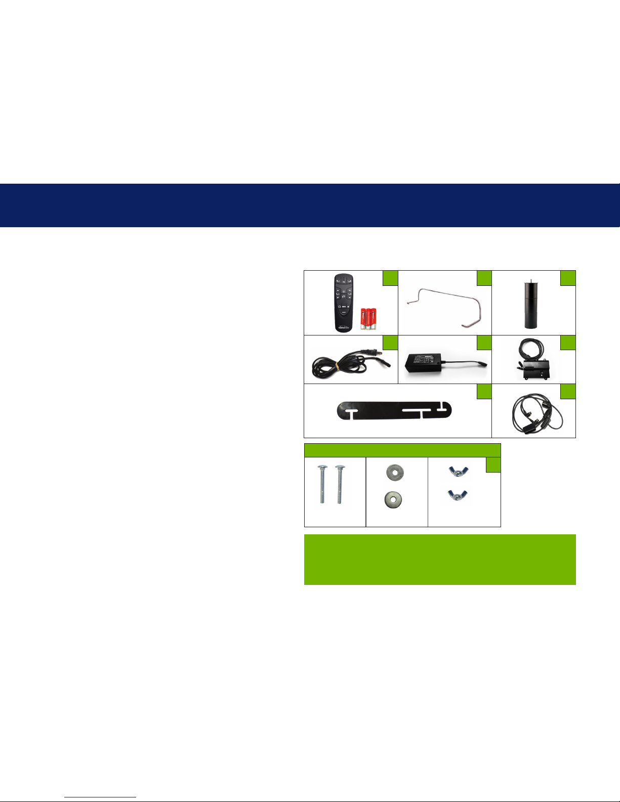
parts list
All electronics and components that need to be installed are
located in boxes under the base or attached to the frame.
A) Wireless Remote Control (1) AAA Batteries (3)
B) Mattress Retainer Bar (1)*
C) Legs (4) (6 Legs included with King/Cal King)
D) Power Cord (1)
E) Power Supply (1)
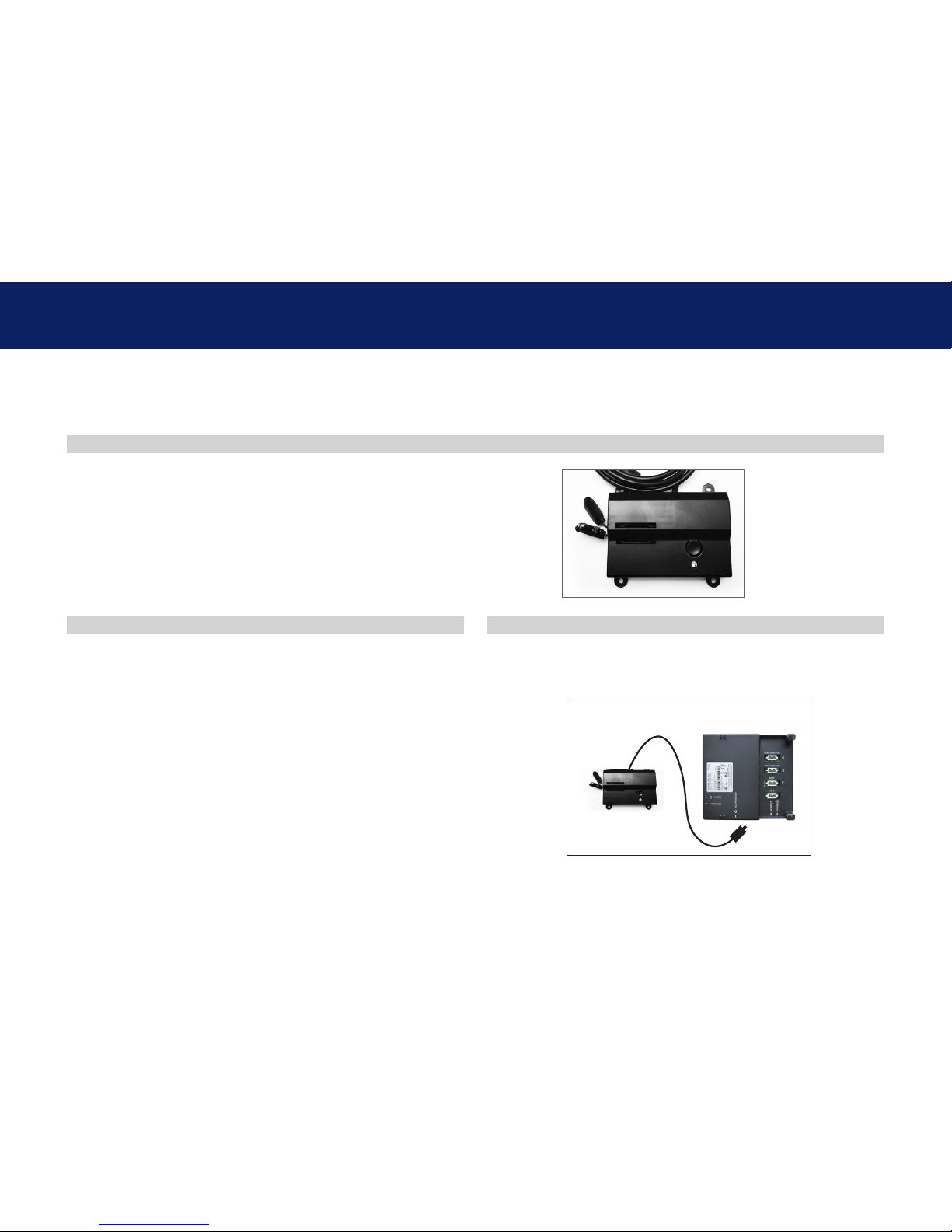
F) Battery Backup Box (1) (9-Volt batteries not included)
G) Connecting Strap ‡*
H) Sync Cord ‡
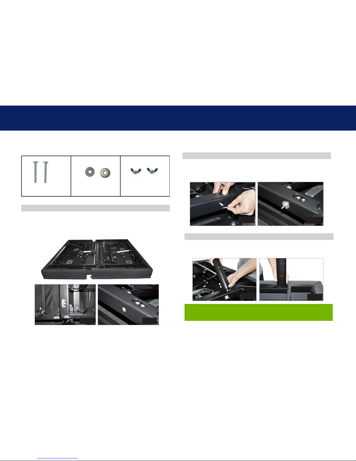
Additional Parts Included with a Divided Base:
I) (2) Long bolts
(2) Washers
(2) Wing nuts
Miscellaneous Parts (not included):
Surge Protector (1)
9 Volt Batteries (2)
* These items are attached to the base for shipping purposes.
Carefully remove from base and set aside.
‡ Only included in Twin Long and California King Split bases.
Before discarding the packing materials, ensure all the parts are accounted for.
A
D
G
Parts Included with a Divided Base
A) B)* C)
D) E) F)
G)‡* H)‡
B
E
C
F
H
IMPORTANT!: For your safety, read the owner’s manual carefully and
completely before operating this product. Electric shock may occur if
electrical components are not installed or operated according to these
guidelines.
I
(2) Washers (2) Wing Nuts
(2) Long Bolts
4
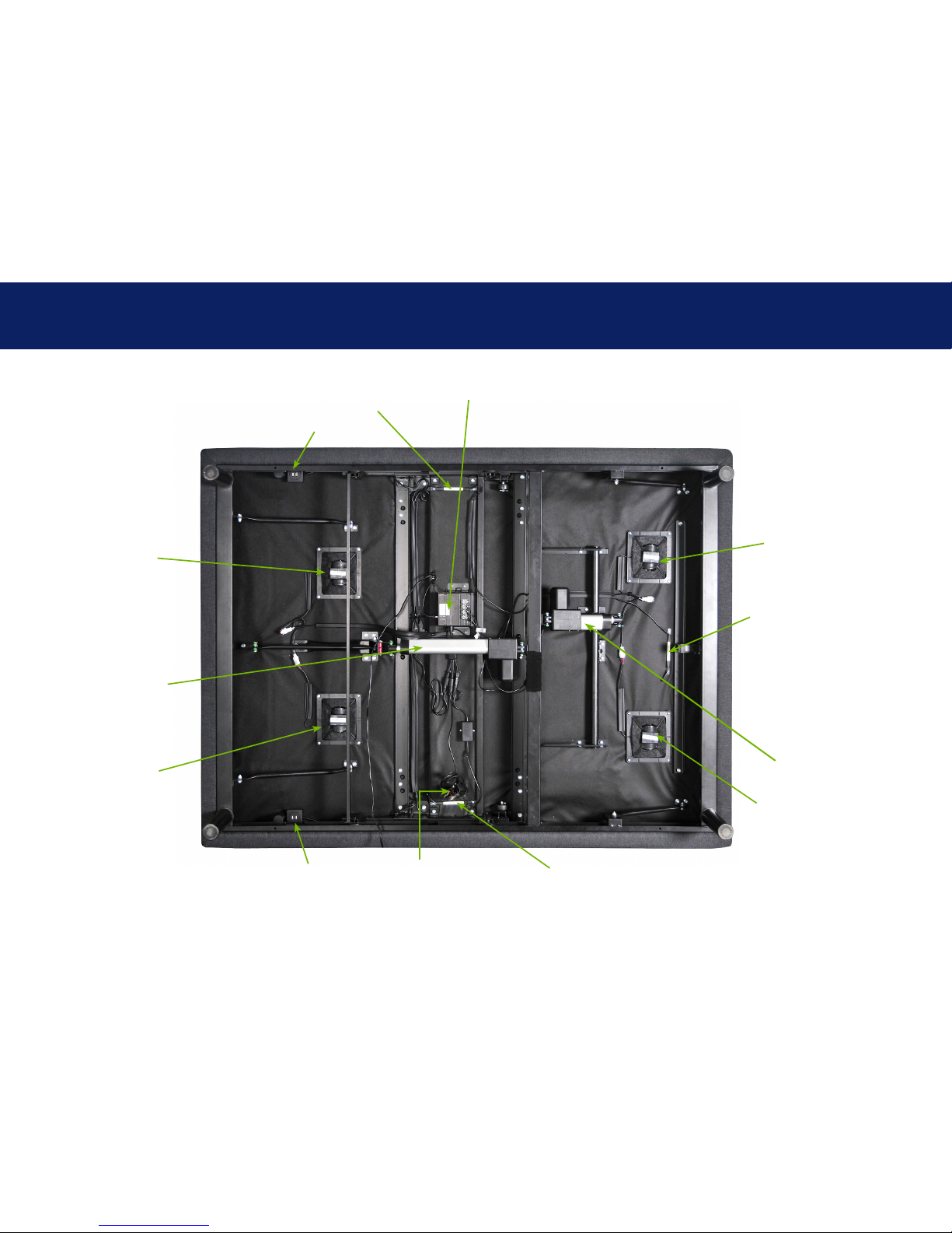
base overview
Foot Motor
Head Motor
Control Box
USB Ports
USB Ports
Massage Motor
Massage Motor
Massage Motor
Massage Motor
Battery Backup Box
Underbed Light
Underbed Light
Underbed Light
5
Not to scale. For illustration purposes only. Read all instructions before beginning installation.
If installing a split unit, see page 15.
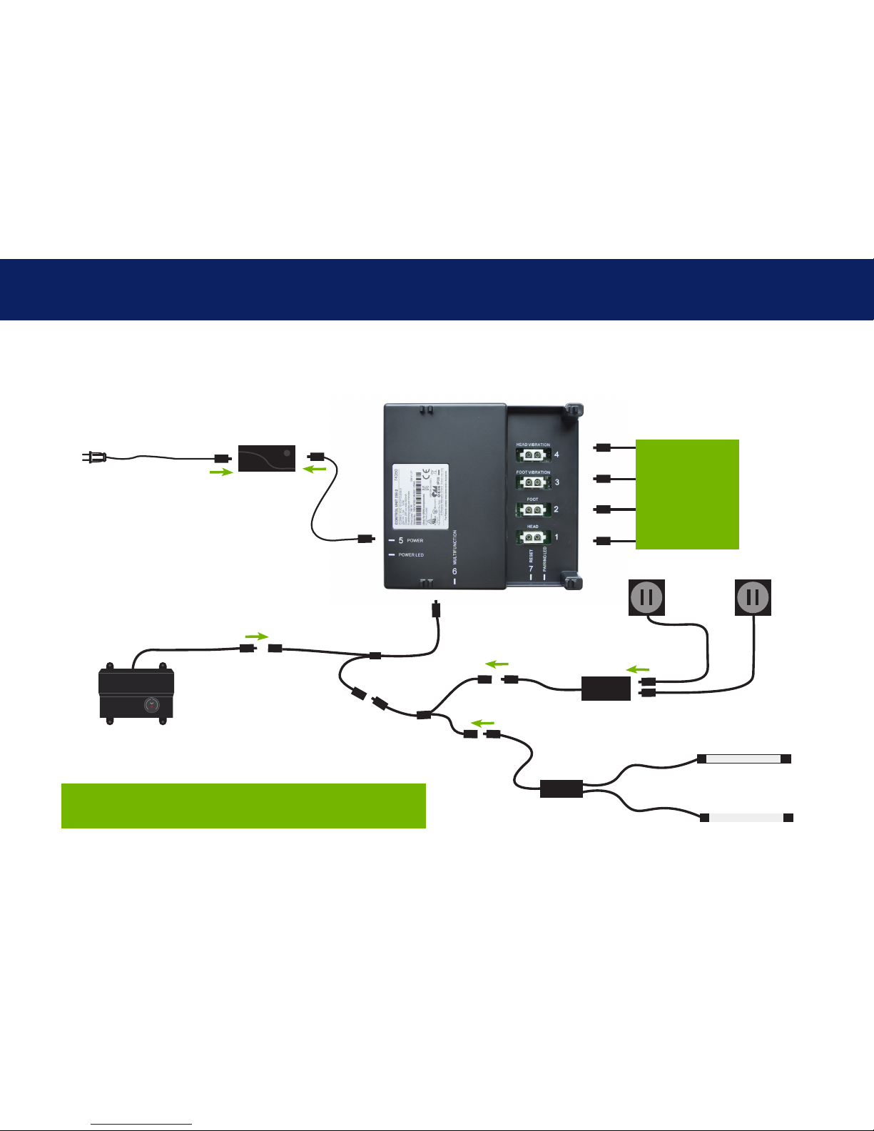
quick reference guide
Power Cord
Input
Power Cord
Power Supply
Control Box
connection ports
to head and foot
motors (massage
and lift). Installed
under the base.
Battery Backup Box
USB Charging Ports
USB Charger
Splitter
Underbed Lighting
Splitter
6
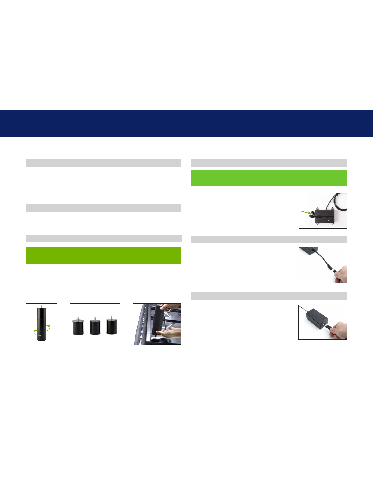
Legs are shipped fully assembled. Alternative heights in 3"
increments can be achieved by removing leg segments.
To install the legs, thread the washer over the bolt of the leg with
the recessed side facing the leg, and tighten by hand. Do not over
tighten.
STEP 1
STEP 2
installation guide
Always use two people when setting up the base.
Place the bed base box in a desired location with the bottom of
the box facing up.
Remove the binding straps and packing materials, making sure
not to puncture the box with any sharp objects.
Remove the bed base from the box keeping the bottom of the
base facing upwards.
STEP 3
STEP 4
STEP 5
STEP 6
Uncoil input power cord (connected to
control box's power port) and plug into
power supply.
If installing a split unit, see page 15.
To install headboard brackets (sold separately), see instructions
on page 16-17.
Locate the battery backup box and install
(2) 9-Volt batteries (not included).
(For operating instructions see page 13).
Uncoil the power cord and connect to the
power supply. Place power supply on the
ground and extend from the base. Ensure
that the power supply and all attached
cords are directed toward the desired
surge protector.
For Tempur-Pedic customer service call: U.S. 1-800-821-6621 | Canada: 1-800-887-4321 | México: 01-722-273-1810
7
STEP 7
STEP 8
STEP 9
Carefully flip the base over on to its legs. Important: Two people
are required to move the bed base. Do not drag across the floor.
Do not rest frame on its side, excessive pressure may damage
the legs.
Plug the power cord into a power source. A surge protector is
recommended.
Ensure batteries are correctly installed in the back of the remote.
Quickly test functions to verify proper setup before placing
mattress on base. Return the base to a flat position before placing
the mattress on top.
Return to page 6 Step 4 for additional setup information.
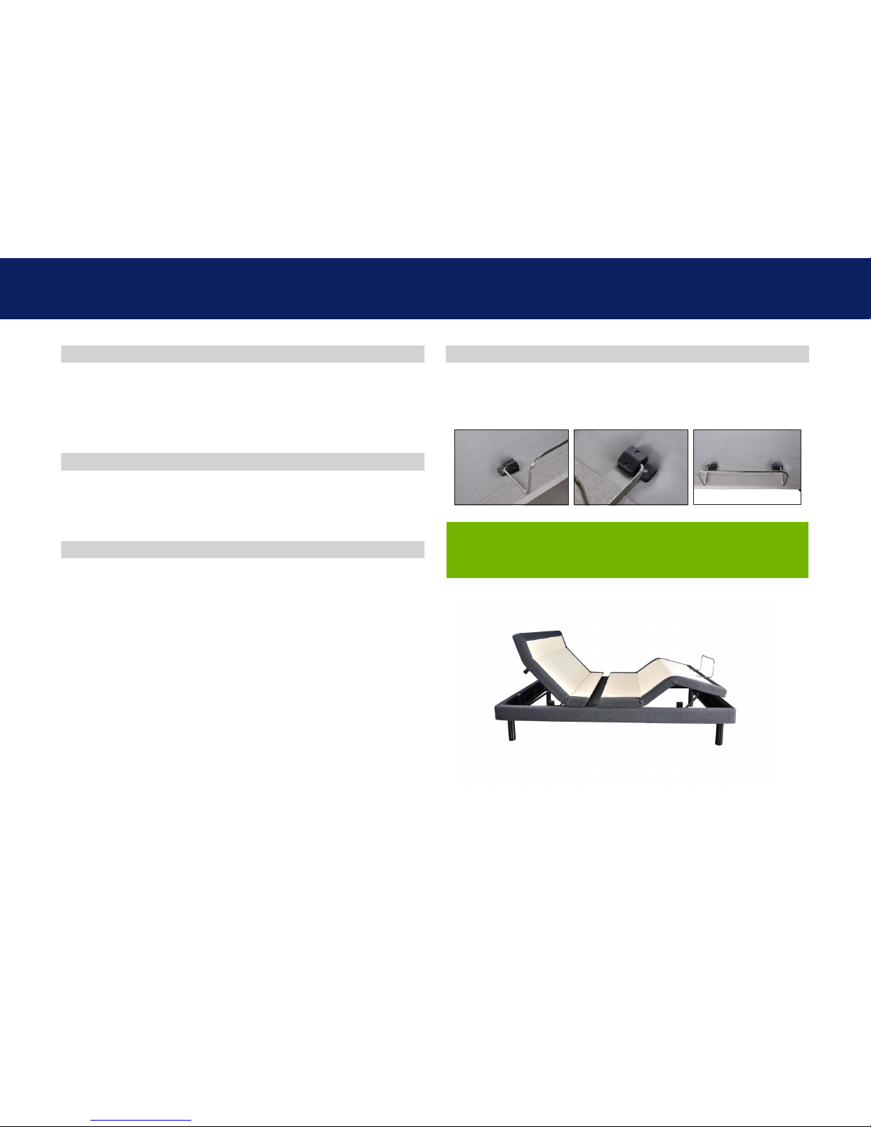
Slide the left side of the mattress retainer bar into the bracket. Pull
the retainer bar to the opposite bracket and secure the right side.
installation guide
STEP 10
For Tempur-Pedic customer service call: U.S. 1-800-821-6621 | Canada: 1-800-887-4321 | México: 01-722-273-1810
8
STEP 1
STEP 3
STEP 2
Always use two people when setting up the base.
Push and align the head and foot sections together. Make sure
to align the leg thread holes with top frame as seen in Fig. A and
side hole as seen in Fig. B.
Once aligned, slide long bolt through the side hole shown in Fig.
C and Fig. D. Secure bolt using one of the washers and wing nuts
provided. Repeat this step for the other side of the base.
To install King/Cal King Headboard Brackets (sold separately) see
instructions on page 16-17.
Attach the legs by screwing them into the leg threads. Do this on
all four corners and both sides of the middle section.
divided base installation guide
(2) Long Bolts
(2) Washers
(2) Wing Nuts
Fig. A Fig. B
Fig. D
Fig. E
Fig. F
Fig. C

9
STEP 4
Connect the head motor and
head massage cables to the
appropriate ports labeled on
the Control Box.
Connect the USB cords to the
USB charger.
divided base installation guide
Fig. G
Setup is now complete!
Please continue with Step 4 on previous page.
10
Remote Control arrives paired to the adjustable base.
Three (3) AAA batteries are required to operate the remote.
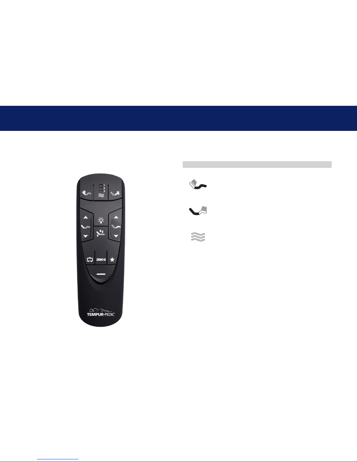
remote control
MASSAGE
Head Zone Massage Control
Activates simple steady-state massage and
toggles through 2 intensity levels. Low, high and
off.
Foot Zone Massage Control
Activates simple steady-state massage and
toggles through 2 intensity levels. Low, high and
off.
Massage Wave Mode Control
Turns on and activates programmed massage
mode. Toggles wave modes 1, 2 ,3 and off.
Intensity default to low.
There are 3 possible wave massage modes and 2 intensity levels to choose
from. Press the Wave Massage Mode Selector to choose the desired mode
(1,2,or 3), then use the Head Massage and/or the Foot Massage buttons
to cycle through the available intensity levels. Once the massage mode is
chosen, it will run for 30 minutes unless it is cancelled by pressing the Wave
Massage Mode Selector button repeatedly until massage stops.
If one of the wave massage modes is not needed, pressing Head and/or Foot
Massage buttons will initiate massage for those sections and cycle through 2
different intensity levels as well as "OFF".

11
remote control
ADJUST
Head Position Adjustments
Use to raise and lower the head section of your
adjustable base.
Foot Position Adjustments
Use to raise and lower the foot section of your
adjustable base.
PRESET
Zero G ‡
Adjusts your legs to relieve pressure off the lower
back.
Flat *
One-Touch Flat lowers head and foot to flat
position and turns off massage (if running).
TV in Bed Preset Position ‡
Brings head and foot into position for viewing TV.
Anti-Snore Preset Position ‡
Raises the head of the bed slightly to help open
airways.
Favorite 1 Preset Position ‡
Reprogrammable Preset Position.
Underbed LED lighting *
Turn on/off underbed LED lighting.
* Not user programmable.
‡ Can be reprogrammed to user desired position.
The ZERO G, TV in Bed, Anti-Snore, and Favorite 1 in bed
presets can be
re-programmed to any position chosen by the user. Simply
adjust the bed to the desired position, then hold any of the 4
buttons down until the remote backlight flashes twice. The
button is now re-programmed.
To restore the buttons to their original positions, depress
the One-touch Flat and Zero-G buttons simultaneously for 5
seconds. The remote backlight will flash twice to indicate the
original positions have been restored.
Remote Control arrives paired to the adjustable base.
Three (3) AAA batteries are required to operate the remote.
12
remote control pairing
Remote Pairing
*ALTERNATE REMOTE PAIRING PROCESS
Locate the control box (see parts list on page 4) and press the
button twice. A green LED light will illuminate on the control
box. On the back of the remote, press and hold the PAIR button.
The PAIR button will illuminate blue and start flashing. When
the PAIR button stops flashing, the green LED light on the
control box will go out. Release the PAIR button. The remote is
now paired to the adjustable base.
Battery backup
box button
PAIR
Button
Test all remote functions. If the remote buttons do not impact
the adjustable base movements, please repeat the process
again or call Tempur-Pedic customer service:
U.S. 1-800-821-6621 | Canada : 1-800-887-4321
México: 01-722-273-1810
STEP 1
STEP 2
The original remote that comes in the box is already paired to the adjustable base. No further action is required. In the event that the
remote is not paired with the base, follow the steps below.
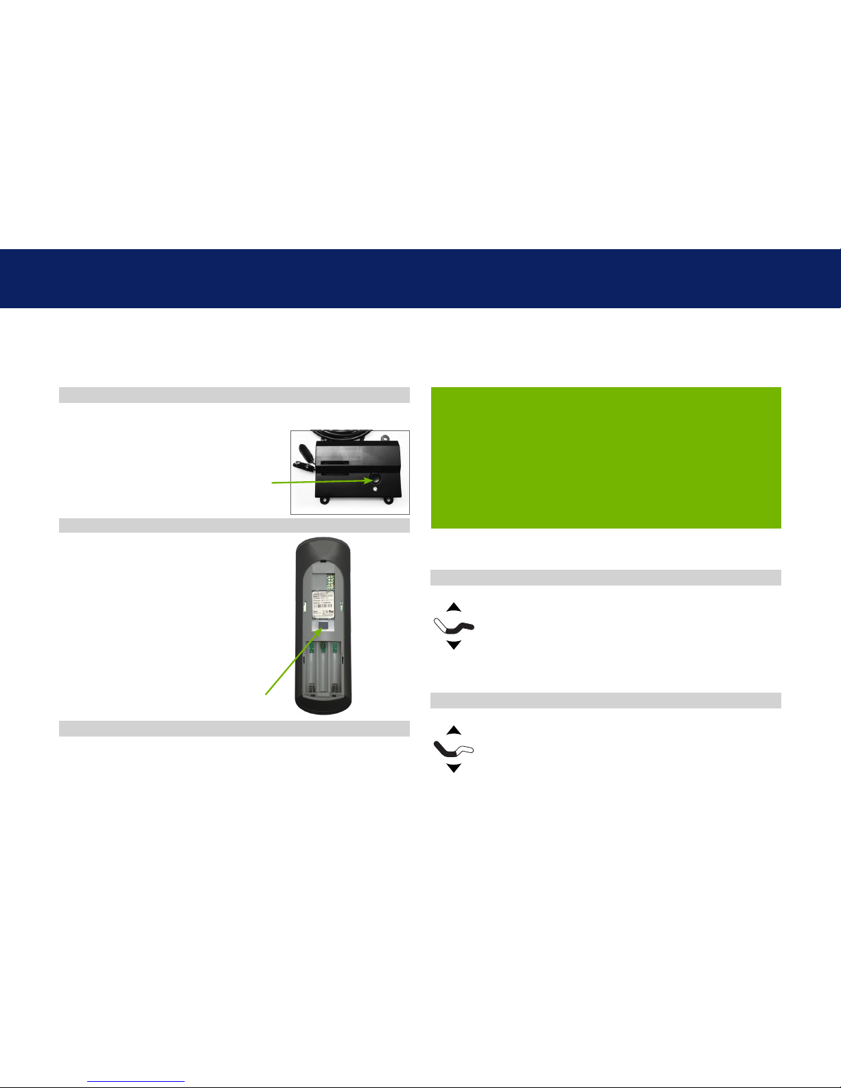
Locate the battery backup box and press
the button TWICE. A light on the battery
back up box will illuminate.
Remove the back cover of the
remote, press and hold down
the PAIR button. The PAIR
button will illuminate blue
and start flashing. When the
PAIR button stops flashing,
the illuminated light on the
battery backup box will go out.
Release the PAIR button. The
remote is now paired to the
adjustable base.
STEP 3
Child Lock Feature
Press and hold HEAD UP and HEAD DOWN buons together
for approximately six (6) seconds. e remote backlight will ash
twice. When the backlight light goes away, the remote is now in
Child Lock. Pressing any buons while in Child Lock will yield no
movement to your adjustable base.
Press and hold FOOT UP and FOOT DOWN buons together
for approximately six (6) seconds. e remote backlight will ash
twice. When the backlight light goes away, the remote is no
longer in Child Lock. e remote and adjustable base will work
normally.
Activate Child Lock
Deactivate Child Lock
13
emergency battery backup box
Two (2) 9 Volt batteries are required to operate the battery backup box feature and are NOT included.
For emergency use only, in case of a power outage.
In the event that the base is stuck in an articulated position
during a power outage, the battery backup box will return
the base to a flat position. Batteries are not to be used for
normal operation of the base.
Install the 9 Volt batteries into the provided battery backup
box.
Do not mix brand name batteries.
Press the button on the battery backup box to lower
the base to flat position.
OVERVIEW
STEP 2
STEP 1
Control Box
Battery Backup
Box
For Tempur-Pedic customer service call: U.S. 1-800-821-6621 | Canada: 1-800-887-4321 | México: 01-722-273-1810
14
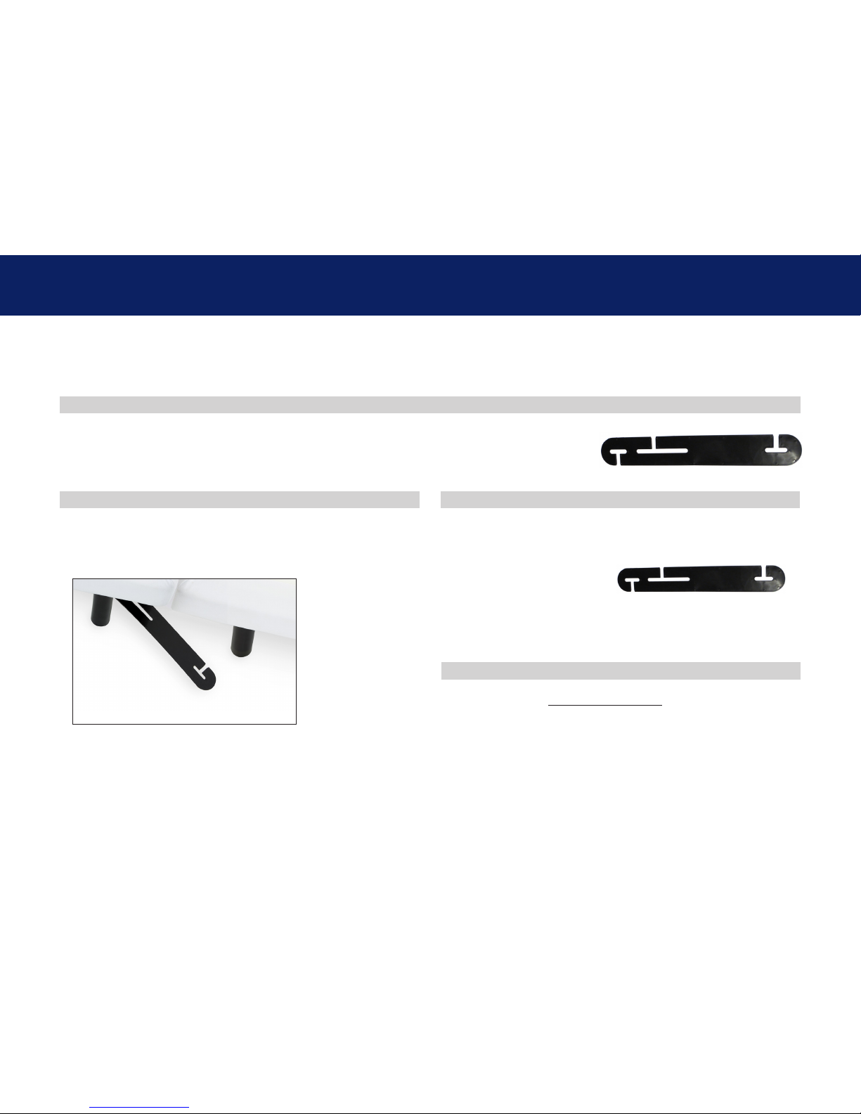
Connecting straps are secured to the base frame upon delivery.
If a split setup is being installed, plastic connecting straps are provided (one per base) to
secure the bases together. Use both straps to secure the head and foot portions together.
With the bases in their desired location, slightly loosen
both legs to allow the strap to fit on the leg bolt, between
the leg washer and frame.
Slide side (a) of the connecting strap onto leg bolt. Swing
the strap and connect side (b) to the leg bolt. Secure the
strap by shifting to the left.
Re-tighten legs. Do not over tighten. Use the remaining
strap on other end of the base.
OVERVIEW
STEP 2
STEP 1
connecting strap (optional)
a
b
STEP 3
15
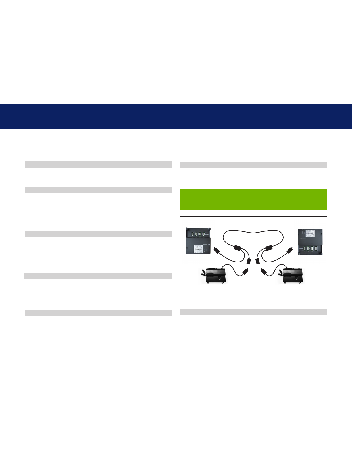
syncing two bases (optional)
A Sync Cord is included with Twing Long and Split Cal King size bases.
The Sync Cord connects the two control boxes to a single remote for the synchronization of two bases.
Disconnect the battery backup box cable from each control
box or splitter cable (make note where the cable was
plugged in).
Plug bases back into the power source.
If bases become mismatched, return both bases to the
flat position to re-sync the bases.
Connect the male end of each sync cord to control box
or splitter cable. Insert it into the same port that you
disconnected the battery backup box from in Step 2.
Check to ensure all cords are securely attached. Both
remotes will now operate both bases simultaneously.
Unplug the base(s) from power source.
Connect each battery backup box male connection to the
sync cord female connection (Refer to illustration at right).
STEP 3
STEP 6
STEP 2
STEP 5
STEP 1
STEP 4
PERFORMANCE NOTES
Battery Backup
Box 1
Sync Cord
Battery Backup
Box 2
Control Box 1 Control Box 2
The system is now linked. Pressed buttons on either remote
will control the two bases simultaneously.
16
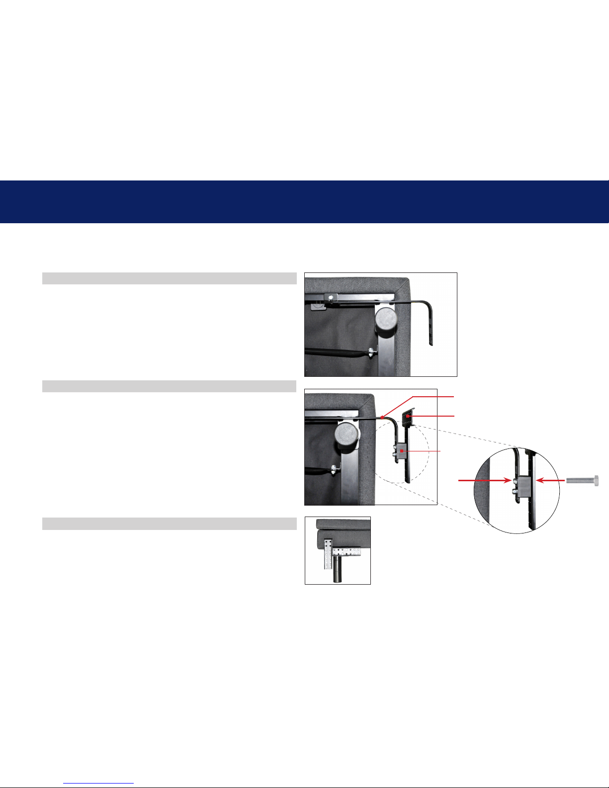
You may now connect your headboard to the attachment plates using the
remaining short bolts and nuts to secure it to the brackets. The heads of
the bolts will face outward. Use a 9/16" socket and 1/2" wrench to tighten
the bolts.
headboard bracket installation guide (optional)
a.) Align the hole in the bracket to the brass sleeve into which the leg
threads. Hold the bracket in place and screw the leg into the base
until it is snug. DO NOT OVERTIGHTEN. Too much force may cause the
leg to spin freely.
b) Align the tab with the hole in the frame (located towards the foot of the
base) and use a short bolt and nut to secure the bracket. Make sure
the bolt is tight.
Attach the plastic spacer and T-Bracket.
a.) Measure the distance between the mounting holes on the headboard
and install the spacer and attachment plate to accommodate the
headboard.
b.) To install the plastic spacer and attachment plate, you will need (2) long
bolts and (2) nuts. Place the spacer and attachment plate in the desired
location and slip the bolts through the holes with the head of the bolt
facing outward. Position the bolts diagonally on the spacer. Use the
9/16” socket and wrench to tighten the bolts.
Headboard Brackets are an optional accessory and are not included.
A 9/16” & 1/2” socket and crescent wrench are necessary to complete installation.
STEP 2
STEP 1
STEP 3
T-Bracket
Headboard
Bracket
Spacer
Long
Bolt
Nut
 Loading...