

Page 1
I.O.M. #152 updated : 05/10/2017
Temperature Controller
INSTRUCTION MANUAL • INSTALLATION • OPERATION • MAINTENANCE
Oil Unit
For Models with the G500 Series Control Instrument
Model:
Serial Number :
TEMPTEK, INC.
525 East Stop 18 Road Greenwood, IN 46142
317-887-6352 fax: 317-881-1277
Service Department fax: 317-885-8683
www.Temptek.com
E-mail: sales@Temptek.com
Page 2

Page 3

Oil Unit
Temperature Controller
INSTRUCTION MANUAL
VTO Series with
G500 Series Instrument
COVERING
INSTALLATION
OPERATION
MAINTENANCE
TEMPTEK, INC. 525 East Stop 18 Road Greenwood, IN 46143
Phone: 317-887-6352 Fax: 317-881-1277 Service Department fax: 317-885-8683
www.Temptek.com E-mail: sales@Temptek.com
Page 4

Temperature Control Unit : VTO Series with G500 Series Instrument
TABLE OF CONTENTS
1.0 GENERAL 7
1.1 Receiving Instructions 8
1.2 Introduction 8
1.3 Safety 8
1.4 Components 10
2.0 INSTALLATION 13
2.1 General 14
2.2 To and from process connections 14
2.3 Water supply connection 15
2.4 Drain connection 15
2.5 Electrical connection 17
3.0 START UP SEQUENCE 19
3.1 General 20
3.2 System Fill / Operations 20
3.3 Instrument : Quick Start 24
3.4 Instrument : Basic Navigation 25
3.5 Instrument : Operating Screens 26
3.6 Instrument : Fault Screens 27
3.7 Instrument : Main Menu 28
3.8 Instrument : Setpoints Menu 28
3.9 Instrument : Utilities Menu 29
3.10 Instrument : Network Menu 30
3.11 Instrument : Options Menu 32
3.12 Instrument : Machine Menu 32
3.13 Shut Down / Disconnect 33
4.0 TROUBLESHOOTING 35
4.1 Unit will not start (Display is not Illuminated) 36
4.2 Unit will not start (Display is Illuminated) 36
4.3 Unit Stops 36
4.4 Unit Overheats 37
4.5 Unit Underheats 38
4.6 Pressure Relief Valve Leaks 38
5.0 MAINTENANCE 41
5.1 Preventative Maintenance 42
5.1 Pump Seal Replacement 43
5.2 Heater Replacement 45
5.3 Cooling Valve Service 46
5.4 Pressure Switch Service 47
5.5 Electronic Instrument Repair Policy And Procedure 48
525 East Stop 18 Road Greenwood, Indiana 46142
TEMPTEK, INC.
317-887-6352 Fax: 317-881-1277
Email: service@Temptek.com
Page: 4
Page 5

Temperature Control Unit : VTO Series with G500 Series Instrument
6.0 COMPONENTS 49
6.1 Mechanical system 50
6.2 Electrical system 50
7.0 RELATED DRAWINGS 53
7.1 Physical 12 kW Heaters & 1 - 3 HP Pumps 54
7.2 Physical 16-24 kW Heaters & 1 - 3 HP Pumps 55
7.3 Physical 36-48 kW Heaters & 5 - 7.5 HP Pumps 56
7.4 Circuit Schematic with Cooling Circuit 57
8.0 APPENDIX 59
8.1 Model # And Suffix Coding 60
8.2 Water Cooled Process Pumps 61
8.3 Mold Purge Operation 62
525 East Stop 18 Road Greenwood, Indiana 46142
TEMPTEK, INC.
317-887-6352 Fax: 317-881-1277
Email: service@Temptek.com
Page: 5
Page 6

THIS PAGE INTENTIONALLY BLANK
Page: 6
Page 7

Temperature Control Unit : VTO Series with G500 Series Instrument
1.0 GENERAL
1.1 Receiving Instructions
1.2 Introduction
1.3 Safety
1.4 Components
525 East Stop 18 Road Greenwood, Indiana 46142
TEMPTEK, INC.
317-887-6352 Fax: 317-881-1277
Email: service@Temptek.com
Page: 7
Page 8

Temperature Control Unit : VTO Series with G500 Series Instrument
1.1 RECEIVING INSTRUCTIONS
A. Temperature control units are generally shipped skid mounted, boxed and wrapped in
plastic prior to shipment.
B. Unbox the unit before accepting delivery. Check for visible damage and document any
evident damage on the delivery receipt or refuse the shipment. Shipping damage is the
responsibility of the carrier.
C. In order to expedite payment for damages, should they occur, follow proper procedures
and keep detailed records. Take photographs of any suspected damage.
1.2 INTRODUCTION
A. This manual covers temperature control units from 12 to 48 kW of heating capacity
using the G500 Series microprocessor control instrument. The standard uid operating
temperature range for this temperature control unit is 100°F to 500°F. Consult the factory
if you have questions about the operating range of your temperature control unit.
B. The intent of this manual is to serve as a guide in the installation, operation and
maintenance of your temperature control unit. Improper installation can lead to equipment
damage and poor performance. Failure to follow the installation, operation and
maintenance instructions may result in damage to the unit that is not covered under the
limited warranty. This manual is for standard products. The information contained in this
manual is intended to be general in nature. The information is typical only and may not
represent the actual unit purchased.
C. When calling for assistance from the Manufacturer’s Service Department, it is important
to know the model and serial number of the particular unit. The model number includes
critical unit information which is helpful when troubleshooting operating difculties. The
serial number allows the service team to locate manufacturing and testing records which
can have additional information relating to a particular unit.
1.3 SAFETY
A. It is important to become thoroughly familiar with this manual and the operating
characteristics of the unit.
B. It is the owner’s responsibility to assure proper operator training, installation, operation,
and maintenance of the unit.
C. Observe all warning and safety placards applied to the unit. Failure to observe all
warnings can result in serious injury or death to the operator and severe mechanical
damage to the unit.
WARNING: This equipment contains hazardous voltages that can cause severe injury or
death. Disconnect and lock out incoming power before installing or servicing the equipment.
525 East Stop 18 Road Greenwood, Indiana 46142
TEMPTEK, INC.
317-887-6352 Fax: 317-881-1277
Email: service@Temptek.com
Page: 8
Page 9
Temperature Control Unit : VTO Series with G500 Series Instrument
CAUTION
WARNING
J5318-BF
D. Observe all safety precautions during installation, startup and service of this equipment
due to the presence of high voltage. Only qualied personnel should install, startup and
service this equipment.
E. When working on this equipment, observe precautions in literature and on tags, stickers
and labels located on the equipment. Wear work gloves and safety glasses.
F. Before installing and operating the unit, be aware of and follow any local laws and codes
that apply to the installation.
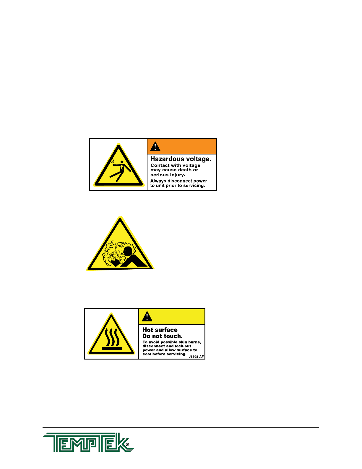
G. Samples of Warning Labels applied to typical temperature control units.
1. Alerts users to the danger of high voltage.
2. Alerts the user to possible explosive danger.
3. Alerts the user to a hot surface danger due to high operating temperatures.
525 East Stop 18 Road Greenwood, Indiana 46142
TEMPTEK, INC.
317-887-6352 Fax: 317-881-1277
Email: service@Temptek.com
Page: 9
Page 10
Temperature Control Unit : VTO Series with G500 Series Instrument
WARNING: Improper fluid quality will void unit warranty.
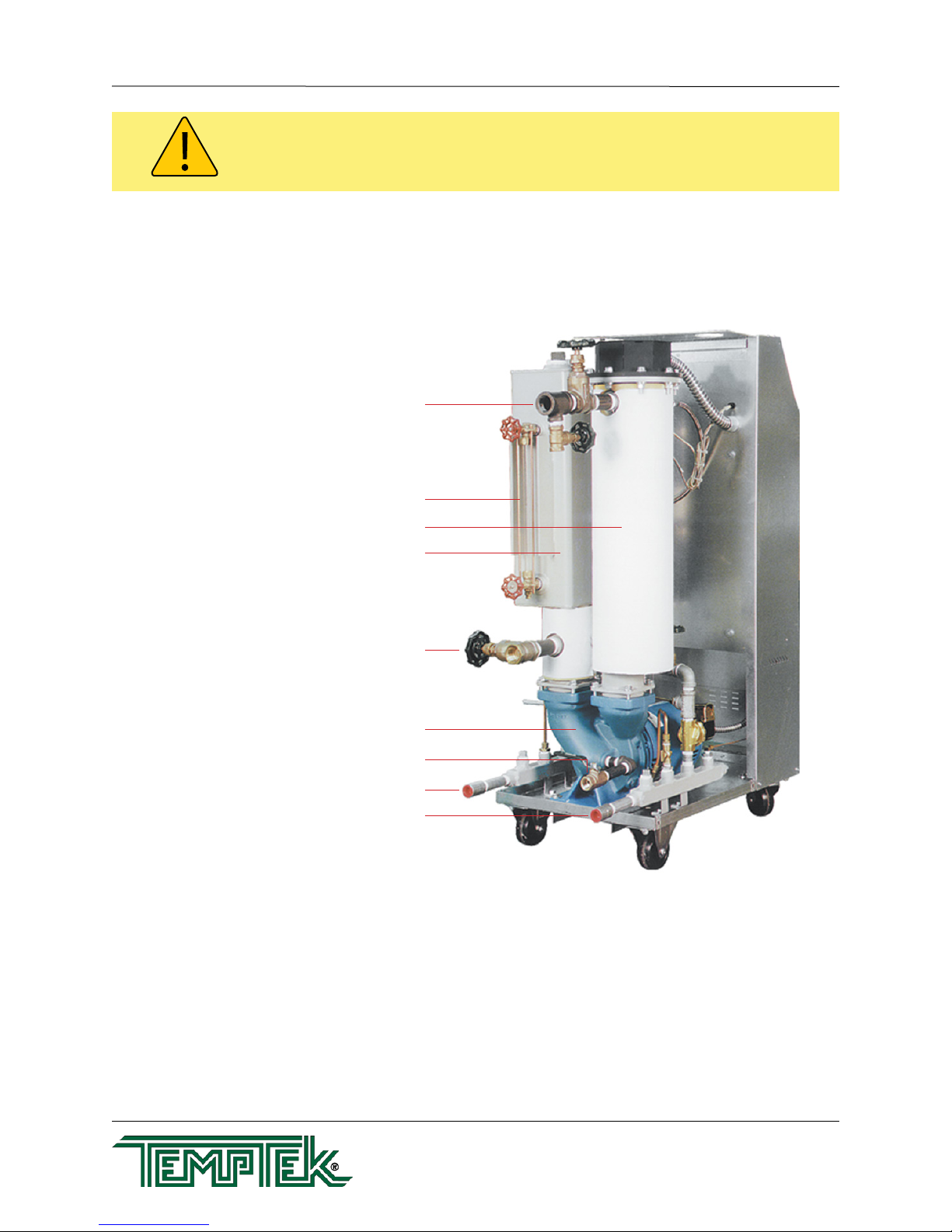
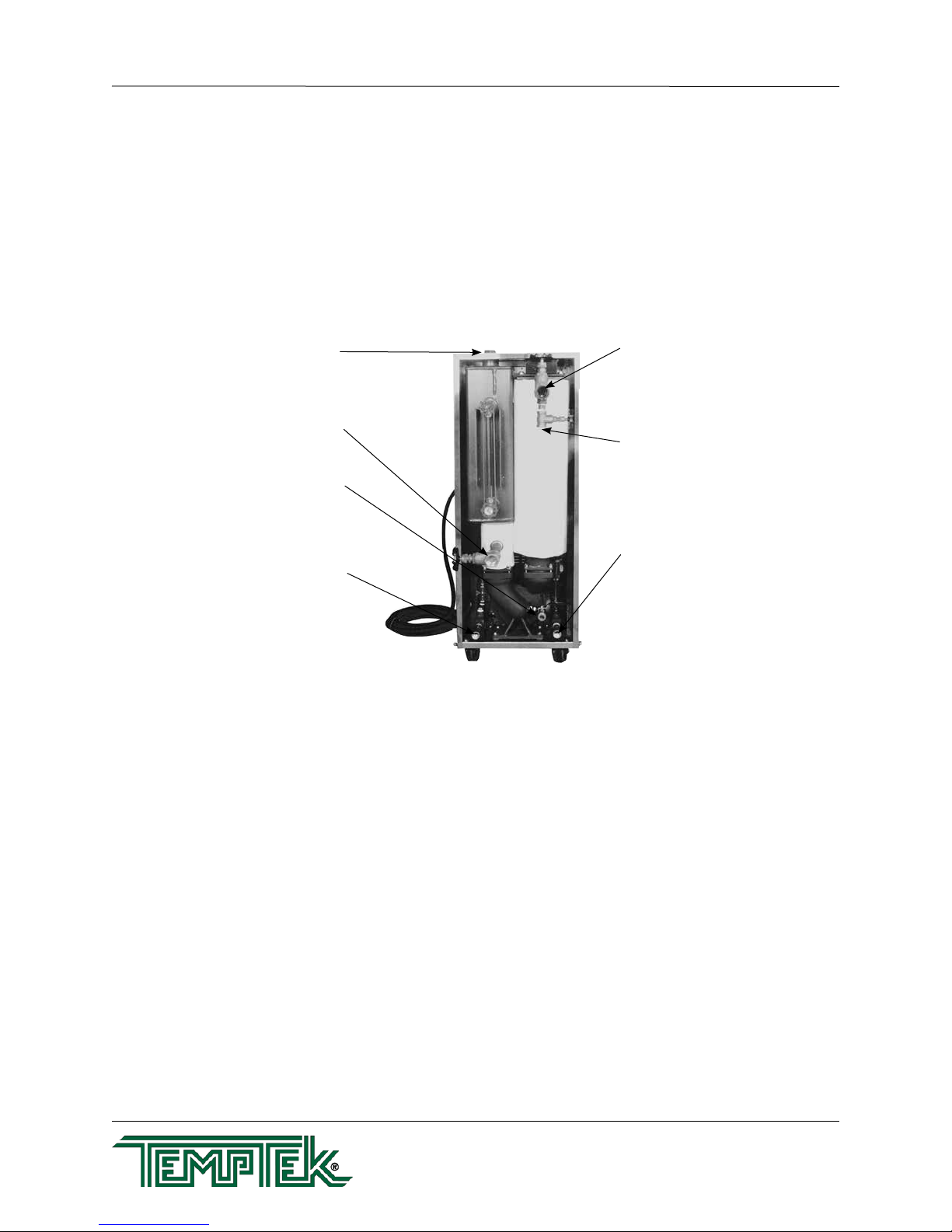
1.4 COMPONENTS
To Process Valve and Connection
Sight Glass
Heat Cylinder
Expansion Tank
From Process Valve and Connection
Process Pump
Fluid Drain Valve
Water Drain Connection
Water Supply Connection
Typical unit with lift-off cabinetry.
525 East Stop 18 Road Greenwood, Indiana 46142
TEMPTEK, INC.
317-887-6352 Fax: 317-881-1277
Email: service@Temptek.com
Page: 10
Page 11
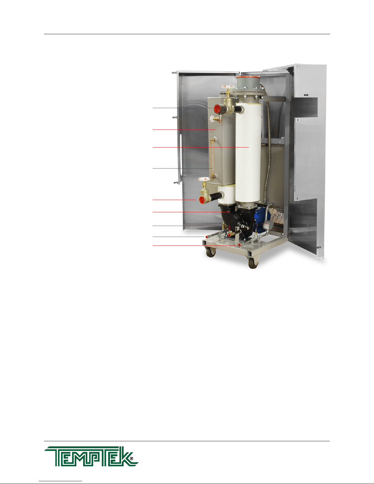
Temperature Control Unit : VTO Series with G500 Series Instrument
To Process Valve and Connection
Expansion Tank
Heat Cylinder
Sight Glass
From Process Valve and Connection
Process Pump
Fluid Drain Valve
Water Drain Connection
Water Supply Connection
Typical unit with clam shell cabinetry.
525 East Stop 18 Road Greenwood, Indiana 46142
TEMPTEK, INC.
317-887-6352 Fax: 317-881-1277
Email: service@Temptek.com
Page: 11
Page 12

THIS PAGE INTENTIONALLY BLANK
Page: 12
Page 13

Temperature Control Unit : VTO Series with G500 Series Instrument
2.0 INSTALLATION
2.1 General
2.2 To and From Process Connections
2.3 Water Supply Connection
2.4 Drain Connection
2.5 Electrical Connection
525 East Stop 18 Road Greenwood, Indiana 46142
TEMPTEK, INC.
317-887-6352 Fax: 317-881-1277
Email: service@Temptek.com
Page: 13
Page 14
Temperature Control Unit : VTO Series with G500 Series Instrument
2.1 GENERAL
A. Care should be taken to use materials (hose, rigid piping, valves or filters) rated for
the temperature and pressure duty of your unit. Most units have a maximum operating
temperature of 500°F or less and a maximum pressure of 75 PSI. The unit is most
efficient when full size plumbing is run from the unit connections to and from the process.
If necessary, reduce the plumbing size at your process, not at the unit.
B. Be certain all process piping materials have the equivalent or larger diameter of the
particular process connection.
Fluid fill port:
Use when manually
adding fluid to the unit
From process
connection:
Connect to “fluid out” on
process manifold
Fluid fill/drain connection:
Use when adding fluid from a
pressurized source or when draining
majority of fluid volume from unit
Water drain connection:
Connect to one of the following:
• Plant’s open water drain
• Tower water system return
• Chilled water system return
2.2 TO AND FROM PROCESS CONNECTIONS
A. Connect the unit’s To Process port to the Fluid In port on the process manifold.
B. Connect the unit’s From Process port to the Fluid Out port on the process manifold.
To process connection:
Connect to “fluid in” on process manifold
Compressed air connection:
Connect to plant compressed air source
when purging fluid from mold to unit for
storage
Water supply connection:
Connect to one of the following:
• Plant’s city water source
• Well water source
• Tower water supply
• Chilled water supply
C. Please note: Process piping circuitry should be designed to avoid an excessive use of
elbows and/or lengths of pipe or hose. If hose is the material of choice, avoid tight twists
or curls and excessive lengths.
.
2.3 WATER SUPPLY CONNECTION
A. Connect the unit’s Water Supply port to the plant’s city water, well water, tower water or
chilled water supply.
B. If unit is a Heating Only Unit, the water supply must be a minimum of 1/2 GPM at a
maximum temperature of 100°F for efcient component cooling. If the unit is a Heating
and Cooling Unit including a heat exchanger, the water supply must be a minimum of
3 GPM at a minimum temperature of 100°F. High water ow may be required for your
application depending on the process cooling requirement.
525 East Stop 18 Road Greenwood, Indiana 46142
TEMPTEK, INC.
317-887-6352 Fax: 317-881-1277
Email: service@Temptek.com
Page: 14
Page 15

Temperature Control Unit : VTO Series with G500 Series Instrument
C. The factory recommend minimum operating water supply pressure requirement is a
minimum of 20 PSI. To protect the unit from operating without adequate supply water, a
water pressure switch is plumbed into the supply manifold. If the supply pressure is not
sufcient, the pressure switch will prevent unit operations.
D. On all units, cooling water circulates to the supply manifold, through the pump adapter
cooling jacket, and is then rejected to the drain manifold. This action maintains proper
pump seal cavity temperatures.
E. On units with the installed cooling option, a tube and shell heat exchanger for process
uid cooling is supplied and mounted to the expansion tank.
1. The purpose of the heat exchanger is to cool the process uid. Cooling water
from plant water supply circulates through the “tube” side of the heat exchanger.
The process uid circulates through the “shell” side. Cooling water ow is
controlled by the solenoid valve.
2. A 1/2” ball valve is placed in the heat exchanger water supply line after the
solenoid valve. The ball valve should be open during operations from 100°F to
200°F. During operations with temperatures over 200°F, this valve should be
closed. In such cases, the necessary cooling water is proportioned to the heat
exchanger through the small capillary line, which some water “steams off” to cool
the process uid. The steam and water mixture is then rejected to drain.
2.4 WATER DRAIN CONNECTION:
A. Connect the unit’s Water Drain port to one of the following, determined by the water
supply source:
1. Open water drain for well or city water supply.
2. Tower water system return for tower system water supply.
3. Chilled water system return for chilled water system supply.
B. The factory recommends a minimum of 20 psi pressure differential between the water
supply and water drain line for proper cooling.
1. For units equipped with the cooling feature, the amount of cooling provided by
the unit depends on:
a. Cooling heat exchanger size.
b. The cooling valve size
c. The pressure differential across the valve
d. The temperature difference between the unit set point and the cooling
water temperature
2. Consult factory when selecting the correct cooling valve for your application.
525 East Stop 18 Road Greenwood, Indiana 46142
TEMPTEK, INC.
317-887-6352 Fax: 317-881-1277
Email: service@Temptek.com
Page: 15
Page 16

Temperature Control Unit : VTO Series with G500 Series Instrument
3. In general, the cooling capacity of the standard 3.5 sq ft heat exchanger is 6,000
Bth/hr (2 kW) for every 20°F difference between the cooling water temperature
and the uid temperature.
C. CAUTION: The unit must never be operated with a closed drain line valve. A closed
drain line valve prevents adequate system cooling and will lead to unit overheating.
Overheating of the unit may lead to unit damage and/or serious personal injury.
WARNING: Never operate the Temperature Control Unit with a closed water drain.
2.5 ELECTRICAL CONNECTION
A. Standard Models
1. Electrical power supply requirements for standard units are identied on the
equipment data tag. Verify that available voltage supply is the same as the unit’s
voltage requirements.
WARNING: DO NOT CONNECT THE UNIT TO A VOLTAGE SUPPLY SOURCE
NOT EQUAL TO THE UNIT’S VOLTAGE REQUIREMENTS AS SPECIFIED ON
THE UNIT’S DATA PLATE.
WARNING: Do not connect the unit to a voltage supply not equal to the unit’s voltage
requirements as specified on the unit’s data plate. Use of incorrect voltage will void the unit’s
warranty and cause a significant hazard that may result in serious personal injury and unit
damage.
Use of incorrect voltage will void the unit’s warranty and cause a signicant
hazard that may result in serious personal injury and/or unit damage.
2. For standard units with 12 kW heaters and up to 3 horsepower pumps, a four
conductor cable, 10 foot in length, is provided for connection to an operator
supplied fused disconnect.
3. For units with 16 kW to 48 kW heaters, the owner must provide a four conductor
power cable and the fused disconnect.
4. The owner supplied fused disconnect must be sized and installed according to
the unit’s power supply requirements and local electrical codes.
B. Models With Factory Included Disconnect Switch and Other Custom Features
1. Some units may be customized and include a factory supplied power disconnect
switch and/or higher specication electrical enclosure. Electrical power supply
requirements are identied on the equipment data tag. Verify that available
voltage supply is the same as the unit’s voltage requirements.
525 East Stop 18 Road Greenwood, Indiana 46142
TEMPTEK, INC.
317-887-6352 Fax: 317-881-1277
Email: service@Temptek.com
Page: 16
Page 17

Temperature Control Unit : VTO Series with G500 Series Instrument
WARNING: Electric Shock Hazard. High Voltage is present in the electrical cabinet.
Disconnect power before servicing. Follow all facility lock-out tag-out procedures.
WARNING: DO NOT connect the unit to a voltage supply source not equal
to the unit’s voltage requirements as specied on the unit’s data plate. Use
of incorrect voltage will void the unit’s warranty and cause a signicant
hazard that may result in damage to the unit or serious personal injury.
2. Appropriate conduit and ttings should be selected which will maintain the
integrity of the cabinet.
3. Supply a power conductor sized according to the unit’s power supply
requirements. Connect the power conductor to the unit’s power supply entry
terminal block.
C. Control Circuit Wiring
1. The unit’s supplied control circuit is 110 volt, 1 phase, 60 cycle. The control circuit
is supplied by the factory installed transformer. A control circuit fuse is provided.
D. General
1. Make certain all ground connections to the unit are properly afxed. A proper
connection to earth ground is required. A conduit ground is not a reliable
conductor!
2. Make certain the power conductor, disconnecting means, and fusing are properly
sized according to the unit’s power supply requirements.
3. Make certain all electrical connections are tightly afxed. Any loose wiring
connections must be tighten before engaging the power supply.
4. Make certain no moisture or standing water is present inside the electrical
cabinet.
525 East Stop 18 Road Greenwood, Indiana 46142
TEMPTEK, INC.
317-887-6352 Fax: 317-881-1277
Email: service@Temptek.com
Page: 17
Page 18
Temperature Control Unit : VTO Series with G500 Series Instrument
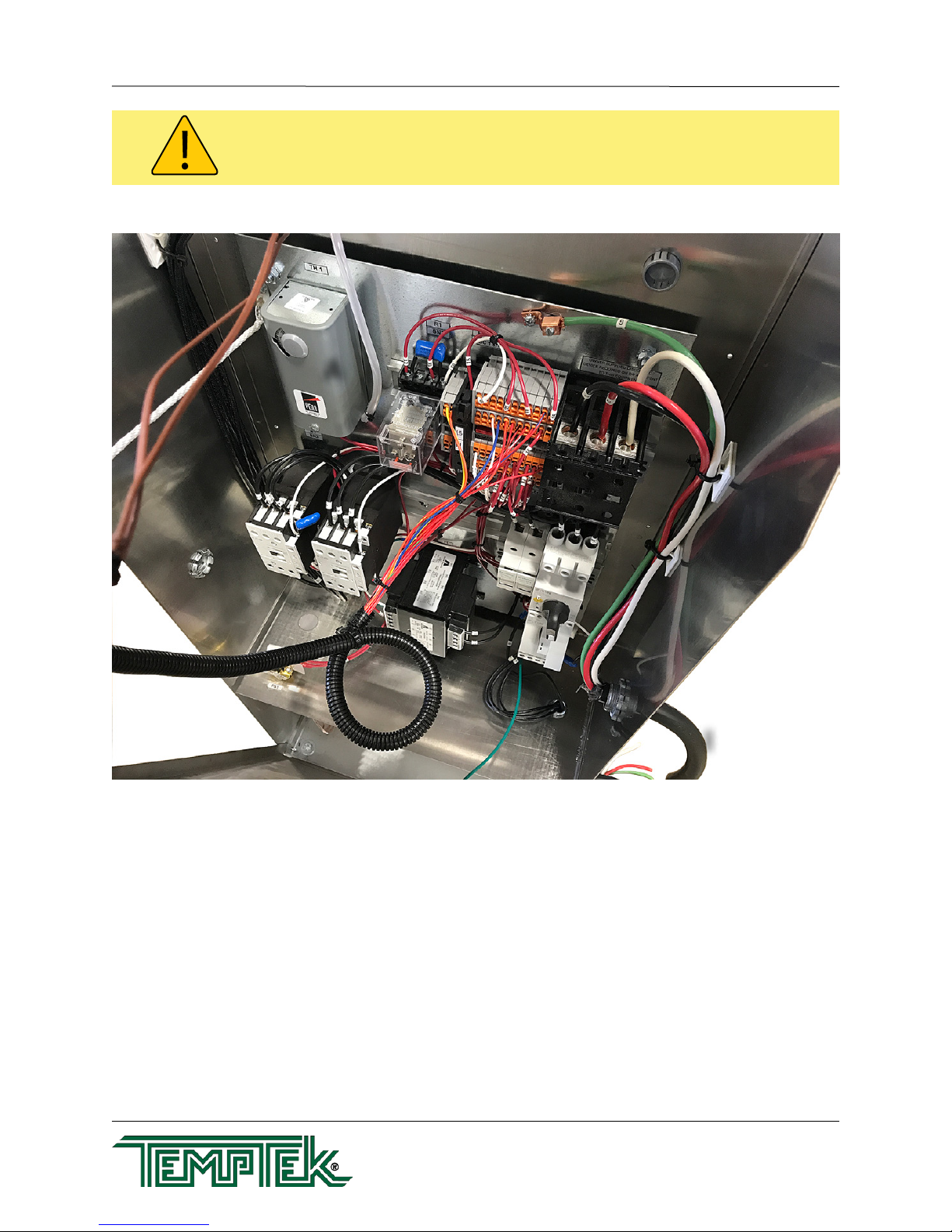
WARNING: Check that all electrical connections are tight before starting.
Disconnect power before servicing. Follow all facility lock-out tag-out procedures.
A
B
C
G
F
E
H
I
Typical Electrical Panel shown as reference of a RK-1230H model. Refer to the electrical drawing available for specific model.
A High temperature limit. Factory set to 515°F.
B High temperature limit instrument relay.
C Power entry terminal block.
D Motor starter and overload block.
E Transformer fuses.
F Control transformer
G Heater contactors
H Water supply pressure switch
I Power Cord. Note : typically included on most 12 kW models with up to 3 HP pumps. Units with 16 kW to 48 kW
heaters and pumps do not include a power cord.
D
525 East Stop 18 Road Greenwood, Indiana 46142
TEMPTEK, INC.
317-887-6352 Fax: 317-881-1277
Email: service@Temptek.com
Page: 18
Page 19

Temperature Control Unit : VTO Series with G500 Series Instrument
3.0 OPERATIONS
3.1 General
3.2 Machine Start Up and Operation
3.3 Instrument Operation : Quick Start
3.4 Instrument : Basic Navigation
3.5 Instrument : Operating Screens
3.6 Instrument : Fault Screens
3.7 Instrument : Main Menu
3.8 Instrument : Setpoints Menu
3.9 Instrument : Utilities Menu
3.10 Instrument : Network Menu
3.11 Instrument : Features Menu
3.12 Instrument : Options Menu
3.13 Instrument : Machine Menu
3.14 Shut Down / Disconnect
525 East Stop 18 Road Greenwood, Indiana 46142
TEMPTEK, INC.
317-887-6352 Fax: 317-881-1277
Email: service@Temptek.com
Page: 19
Page 20

Temperature Control Unit : VTO Series with G500 Series Instrument
3.1 GENERAL
A. Failure to follow the factory required operation procedures may adversely affect the unit’s
ability to adequately control process temperature and may create a hazardous operating
condition which may result in unit damage or serious operator injury.
B. The Operations segment of this manual is outlined below:
WARNING: Follow all Factory operations procedures. Failure to do so may create a
hazardous operating condition which may result in serious operator injury and/or unit damage.
3.2 Machine start-up/operations procedure - follow this segment to start the unit
after the initial installation or to restart the unit after reinstallation to the same or
different process. This section includes information on system ll, electric motor
phasing (pump rotation) and process ow adjustments.
3.3 Instrument Operation - follow this segment to start up and operate the
instrument. This section includes information on setpoint selection and
adjustment and feature explanations.
3.4 Shut down procedure - follow this segment to shut down the unit. This segment
includes information on system cool down, shut down, electrical power supply
precautions, and disconnection from the system.
3.2 MACHINE START UP AND OPERATION
A. System Fill
1. Use only approve high temperature heat transfer uids in this unit such as
Paratherm NF or an equivalent uid (www.paratherm.com). Never use water in
this unit.
List of Approved Heat Transfer Fluids
• Paratherm OR (https://www.paratherm.com/heat-transfer-uids/paratherm-or-heat-transfer-uid/)
• Paratherm NF (https://www.paratherm.com/heat-transfer-uids/paratherm-nf-heat-transfer-uid/)
• Multitherm PG-1 (http://www.multitherm.com/multitherm-pg-1.html)
• Calo FG (https://lubricants.petro-canada.com/productoverview/brand/calo)
2. The primary method of system ll is through the ll port located on the top of the
unit. Simply remove the cap plug and add uid. Replace the cap plug and tighten
when the ll is complete.
3. The alternate method of system ll is through the ll/drain valve. If a pressurized
source is available, simply connect to the ll/drain valve, open the valve and
engage the supply source. Close the valve when the ll is complete.
4. Proper unit ll is essential for efcient and safe operation. An oil level sight
glass is provided to determine unit ll. For initial ll: units up to 12 KW - ll until
525 East Stop 18 Road Greenwood, Indiana 46142
TEMPTEK, INC.
317-887-6352 Fax: 317-881-1277
Email: service@Temptek.com
Page: 20
Page 21

Temperature Control Unit : VTO Series with G500 Series Instrument
the sight glass is 1/2 full; for units up from 27 to 48 KW ll until the sight glass
is completely full. When the pump is rst started, the oil level will drop as the
heater tank and process are lled. After which, the operator may need to top off
as necessary to maintain oil level near the bottom of the sight glass. Check the
system for any leaks and repair if necessary.
WARNING: Electrical power is engaged and caution should be employed while the cabinet is
open.
B. Electric Motor Phasing (Pump Rotation)
1. The operator must determine the electric motor is phased correctly. This is done
by visually inspecting the rotation of the motor shaft as outlined below. Incorrect
phasing of the unit results in poor operation and eventual damage.
a. Supply electrical power to the unit by engaging the unit’s disconnect
switch. Once the correct voltage is supplied to the unit, the Power light
on the display will illuminate.
b. Open the hinged electrical cabinet panel
cover. Note that the electrical power
is engaged at this point and caution
must be observed while the electrical
supply is engaged and the cabinet
panel is open.
c. Locate the electric motor and identify
the motor shaft inside the electric motor
housing. The motor shaft can be seen
through the vent slots in the motor
housing or by removing the shaft cover.
Remove shaft cover to view the
motor shaft.
d. Toggle the On / Off buttons. This will
cycle the motor “on” and then “off”.
e. Observe the motor shaft as it slows to
a stop to identify the rotation. Correct
rotation is “clockwise”, when viewed
from the rear of the motor. Incorrect
rotation is “counter-clockwise” when
viewed from the rear of the motor. If
the shaft does not rotate when the unit
is started, the operator must identify
the cause as outlined in this manual’s
Correct rotation is clockwise when
viewed from the rear of the motor.
troubleshooting and repair section.
f. If the unit is phased correctly, continue with the start up procedure at step
C. If the unit is phased incorrect, continue with step 2.
525 East Stop 18 Road Greenwood, Indiana 46142
TEMPTEK, INC.
317-887-6352 Fax: 317-881-1277
Email: service@Temptek.com
Page: 21
Page 22

Temperature Control Unit : VTO Series with G500 Series Instrument
2. To correct unit phase:
a. Disengage the electrical power supply to the unit at the unit’s disconnect
switch. Follow proper lockout procedures before proceeding.
b. Once the electrical power supply is disengaged, reverse any two power
leads of the power cord at the fused disconnect terminals.
c. Note: The operator must reverse the power leads at the disconnect
only and not at the power entry terminals on the unit’s electrical
panel. The unit’s internal electrical system wiring is phased correctly at
the factory and must not be altered in the eld.
WARNING: To correct phase ... switch power leads at the disconnect switch only.
C. Process Flow Adjustments
1. The operator must determine and set proper uid ow rate for the most efcient
and trouble free operation.
a. Fluid ow rate through the process is determined by the pressure losses
in the process loop. Generally, higher ow rates result in turbulent ow
achieving maximum temperature control and lower maintenance.
b. If the ow rate exceeds the motor horsepower capacity, the electric motor
will draw excessive amps. This is a result of the process loop’s ability to
ow uid at a greater rate than can be provided by the pump. This will
eventually result in tripping the motor overload relay (overload relays
open) and the unit will shut down and the instrument will indicate an
alarm condition.
2. If an excessive ow situation is encountered and the motor overload circuit
has tripped, the operator must manually reset the overload relay before
operations can continue. Disconnect from power and follow proper lock out tag
out procedures prior to opening the electrical panel cover and identifying the
overload relay.
Overload relays have a switch (pictured below). This switch will be positioned
with the indicator pointing up when in normal operation. The indicator will be
pointing to the left when the overloads are tripped. To reset, simply turn the
Normal Operating Position Tripped Position
525 East Stop 18 Road Greenwood, Indiana 46142
TEMPTEK, INC.
317-887-6352 Fax: 317-881-1277
Email: service@Temptek.com
Page: 22
Page 23

Temperature Control Unit : VTO Series with G500 Series Instrument
WARNING: Electrical power is engaged and caution should be employed while the cabinet is
open.
switch to where the indicator points up.
Some older models have overload relay where a red button that pops out if the
overloads are tripped. Simply push the button in until the overloads are reset.
3. If a motor overload situation persists, the operator must adjust the ow rate to
match the system pressure loss (reduce ow rate) to prevent continual tripping of
the overload relay.
a. Open electrical cabinet panel door. The panel cover is hinged and held
open by a support cable. Note that the electrical power is engaged at
this point and caution must be observed while the cabinet panel is
open.
b. Identify the motor starter block. This block consists of the motor starter
contactor and the overload relay.
c. Place an amp meter on a single power lead coming from the overload
relay.
d. Locate the motor name plate on the pump motor housing. The full load
amp rating for the motor is listed on the name plate.
e. Engage the electrical power supply and start the unit.
f. The amp meter will display the motor amps. Compare the actual motor
amps as displayed on the amp meter to the full load amp rating as listed
on the motor name plate.
g. If the amp draw is excessive (higher than the listed name plate amp
rating), a throttling valve must be installed in the “from process” line. The
throttling valve can be a gate valve or a ball valve.
h. With the throttling valve installed, fully close the valve and then engage
the pump motor. Slowly open the throttling valve and monitor the motor
amps as displayed on the amp meter until the actual motor amps
equal the listed full load amp rating of the motor. The process ow is
now correctly adjusted. The valve should remain in this position during
operation.
6. LOW PROCESS FLOW: The minimum recommended process ow rate is 50%
of unit rated ow. Process restrictions may limit the ow to less than 50%. We
recommend the addition of bypass lines to raise the ow rate to 50%. The best
place to add bypass lines are on the extra ports on the process manifold. If extra
ports are not available, add a tee in the To Process and From Process lines,
install a bypass line between the two tees with a throttling valve. Adjust the valve
for a minimum of 50% of unit rated ow.
525 East Stop 18 Road Greenwood, Indiana 46142
TEMPTEK, INC.
317-887-6352 Fax: 317-881-1277
Email: service@Temptek.com
Page: 23
Page 24

Temperature Control Unit : VTO Series with G500 Series Instrument
Arrow and Select Keys Display Window Power On Button
3.3 INSTRUMENT : QUICK START
Power Off Button
1. Apply power. The Standby screen will illuminate. When Standby is displayed on the
screen, the unit is not running.
2. This unit features an LCD screen. Use the five soft touch buttons to navigate the
available screens and select parameters.
3. A System Safety Fault may prevent startup. Probe, water supply pressure, pump
overload or high temperature limit may display once power is applied and must be
corrected prior to operation.
Sample of Fault display screens. Not all Fault screens are shown here.
4. Adjust the setpoint to the desired value by pressing the Increment or Decrement buttons.
525 East Stop 18 Road Greenwood, Indiana 46142
TEMPTEK, INC.
317-887-6352 Fax: 317-881-1277
Email: service@Temptek.com
Page: 24
Page 25

Temperature Control Unit : VTO Series with G500 Series Instrument
5. The unit is ready to start when no errors are shown on the screen. Press the green start
button.
To Process
Standby
Ready
SetpointStatus
100°F
6. The unit will heat or cool to maintain the setpoint temperature.
3.4 INSTRUMENT : BASIC NAVIGATION
Setpoint : 100°F
Heating : 100%
75°F
A. The instrument has 5 soft keyed buttons.
1. The Home button, when pressed , shows the Home
screen.
2. The Up button, when pressed, will add one unit of
value or will scroll up through a menu.
3. The Down button, when pressed, will subtract one
unit of value or will scroll down through a menu.
4. The Go button, when pressed, will advanced
through a series of screens or save a value.
5. The Back button, when pressed will go backwards
through a series of screens.
B. Prompts on Selection Screens. Selection screens display a
menu of selectable items.
1. The Up button will scroll up through the menu items.
The screen indicators will scroll along with the
pressing of the button.
2. The Down button will scroll down through the menu
items. The screen indicators will scroll along with the
pressing of the button.
Back
Home
Up
Down
Go
3. The Go button will advance to the value screen of the
selected parameter.
4. The Back button will return to the previous screen.
Successive pressing of the Back button will
eventually end at the Home screen.
C. Prompts on Value Screens. Value screens allow the user to
set or change parameter values.
1. The Up button will add to the value of the parameter.
525 East Stop 18 Road Greenwood, Indiana 46142
TEMPTEK, INC.
317-887-6352 Fax: 317-881-1277
Email: service@Temptek.com
Page: 25
Page 26

Temperature Control Unit : VTO Series with G500 Series Instrument
Vertical Indicator
2. The Down button will subtract value from the parameter.
3. The Go button will save the new value to memory.
4. The Back button will cancel the transaction and will
return to the parent screen.
D. Prompts on Success Screens. Success screens appear
once a value is changed and the new value is successfully
saved. The screen shows the name of the parameter and
displays “Success” as indication the value was saved.
1. Use the Go or Back buttons to acknowledge the
prompt.
2. After acknowledging the success, the screen returns to the parent screen.
E. Screen Indicators.
1. Small indication triangles are used as on screen
pointers.
2. The horizontal indicators point to the current
selection. By pressing the Go button, the
screen advances to that selection.
3. The vertical indicator shows that some menu
items are not currently shown on the screen. By
pressing the Down button, the menu will scroll
down to display the menu items not currently
visible. By pressing the Up button, the menu will scroll up.
3.5 INSTRUMENT : OPERATING SCREENS
A. The instrument displays several operating screens to indicate what the unit is doing
as far as heating, cooling and other functions if available. In most operating screens,
the To Process temperature is shown with the operation indicated under the setpoint
temperature, as shown in the example below.
B. Heating. The amount of heating applied to the process is indicated in the Heating
Screen.
Horizontal Indicators
525 East Stop 18 Road Greenwood, Indiana 46142
TEMPTEK, INC.
317-887-6352 Fax: 317-881-1277
Email: service@Temptek.com
Page: 26
Page 27

Temperature Control Unit : VTO Series with G500 Series Instrument
3.6 INSTRUMENT : FAULT SCREENS
A. Faults Preventing Start Up or Operation :
1. System Safety. This fault screen appears if the following occurs:
a. Water Pressure. The unit will not operate without adequate water supply
pressure. Sufcient water supply pressure must be present to close
the water pressure switch. Recommended water supply pressure is 20
PSI. Water supply pressure should not exceed 55 PSI. If water supply
pressure exceeds 55 PSI, a pressure reducing valve must be installed in
the water supply line.
b. Motor Overload. The unit will not start or run if the motor overload
is tripped. During operations, this error is triggered by excessive ow
causing the pump to draw more amps then it is rated for. A throttling
valve should be placed in the from process line to control ow.
2. High Temp. If process temperature exceed 515°F, the high temperature limit
switch opens and the unit shuts down. High temperature conditions are generally
caused by inadequate water supply pressure, a defective cooling valve, an
obstructed drain line or high back pressure in the drain. Determine the cause and
correct. See the troubleshooting section of this manual for more information. The
high temperature limit switch will automatically reset as the unit cools.
B. Faults Not Preventing Start Up or Operation :
1. To Process Sensor. This fault screen will appear if the To Process temperature
sensor is defective and needs to be replaced or if the sensor connection is wet
or loose.
525 East Stop 18 Road Greenwood, Indiana 46142
TEMPTEK, INC.
317-887-6352 Fax: 317-881-1277
Email: service@Temptek.com
Page: 27
Page 28

Temperature Control Unit : VTO Series with G500 Series Instrument
3.7 INSTRUMENT : MAIN MENU
A. The Main Menu offers the ability to set and change values in the following areas:
1. Setpoints.
2. Utilities.
3. Network.
4. Features.
5. Machine.
B. The Main Menu is accessible from the Standby screen by pressing the Go button.
Standby
Ready
C. The Main Menu is also accessible from any Operating screen by pressing the Go button.
In the example below, while on the Cooling screen, pressing the Select button will
advance to the Main Menu.
SetpointStatus
500°F
Main Menu
Setpoints
Utilites
Network
Features
Machine
Back Pick Go
To Process
101°F
Setpoint: 500°F
Heating: 100%
3.8 INSTRUMENT : SETPOINTS MENU
A. Under the Setpoints menu item, the values for the Process Setpoint, Hi Deviation, Low
Deviation can be set or changed.
B. Process Setpoint. Use the Up or Down buttons to change the process setpoint.
Setpoints
Process Setpoint
Hi Deviation
Lo Deviation
Back Pick Go
1. The Setpoint range is from 100°F to 500°F. Please note, the unit can not reduce
process temperature below the provided water supply temperature.
Process Setpoint
Cancel
500°F
Adjust OK
Main Menu
Setpoints
Utilites
Network
Features
Machine
Back Pick Go
Change Setting
Process Setpoint
Success
Acknowledge
2. Once acknowledged, the unit will control to the new setpoint temperature. Press
the Back button repeatedly to return to the Setpoints screen or press the home
button to return to the Home screen.
525 East Stop 18 Road Greenwood, Indiana 46142
TEMPTEK, INC.
317-887-6352 Fax: 317-881-1277
Email: service@Temptek.com
Page: 28
Page 29

Temperature Control Unit : VTO Series with G500 Series Instrument
Setpoints
Hi Deviation
Lo Deviation
Process Setpoint
Back Pick Go
Hi Deviation
5°F
Cancel
Adjust OK
Change Setting
Hi Deviation
Success
Acknowledge
Setpoints
Hi Deviation
Lo Deviation
Process Setpoint
Back Pick Go
Lo Deviation
5°F
Cancel
Adjust OK
Change Setting
Lo Deviation
Success
Acknowledge
Utilities
Software Version
Display Test
Display Sensors
Back Pick Go
Setpoints
Utilites
Network
Features
Machine
Back Pick Go
Main Menu
Utilities
Display Test
Display Sensors
Software Version
Back Pick Go
Software Version
c4139887ele0729
maC8432_2017.a
Back
C. Hi Deviation. The High Deviation value programs the controller to sound the alarm if the
process temperature exceeds the set difference from setpoint. For example, Hi Deviation
= 5°F, Setpoint = 200°F. Hi deviation alarm will sound if the temperature reaches 205°F.
1. The factory default is 10°. The range for the Hi Deviation is from 0°F - 50°F.
2. Once acknowledged, press the Back button repeatedly to return to the Setpoints
screen or press the home button to return to the Home screen.
D. Lo Deviation. The Lo Deviation value programs the controller to sound the alarm if the
process temperature exceeds the set difference from setpoint. For example, Lo Deviation
= 5°F, Setpoint = 200°F. Lo deviation alarm will sound if the temperature cools to 195°F.
1. The factory default is 10°. The range for the Lo Deviation is from 0°F - 50°F.
2. Once acknowledged, press the Back button repeatedly to return to the Setpoints
screen or press the home button to return to the Home screen.
3.9 INSTRUMENT : UTILITIES MENU
A. Items in the Utilities menu include the operations for the Software Version, Display Test
and Display Sensors.
B. Software Version. The software version number is the current version of the controller’s
software. This number came be useful when troubleshooting at times.
TEMPTEK, INC.
525 East Stop 18 Road Greenwood, Indiana 46142
317-887-6352 Fax: 317-881-1277
Email: service@Temptek.com
Page: 29
Page 30

Temperature Control Unit : VTO Series with G500 Series Instrument
Network
Baud Rate
Address
Protocol
Back Pick Go
Setpoints
Utilites
Network
Features
Machine
Back Pick Go
Main Menu
Setpoints
Utilites
Network
Features
Machine
Back Pick Go
Main Menu
Setpoints
Utilites
Network
Features
Machine
Back Pick Go
Main Menu
Setpoints
Utilites
Network
Features
Machine
Back Pick Go
Main Menu
Utilities
Display Test
Display Sersors
Software Version
Back Pick Go
Utilities
Display Test
Display Sersors
Software Version
Back Pick Go
Sensor Display
To Process:
037.7°C (100°F)
Cold Junction:
033.5°C (92°F)
Network
Baud Rate
Address
Protocol
Back Pick Go
Protocol
SPI CCP
Modbus RTU
CAMAC
Cancel
Adjust OK
Change Setting
Protocol
Success
Acknowledge
1. Select the Software Version item from the Utilities Menu to advance to the
software version screen.
2. Press the Back button to return to the Utilities menu.
C. Display Test. The Display Test will test the entire for bad pixels or sectors.
1. Select the Display Test item from the Utilities Menu to advance to the Display
Test screen.
2. The test will show a blank screen. If any bad pixels or sectors are detected, those
pixels or sectors will be dark. If dark pixels or sectors are indicated, contact the
factory repair or replacement options.
D. Display Sensors. Not active on this unit
3.10 INSTRUMENT : NETWORK MENU
A. Items in the Network menu include Protocol, Address and Baud Rate
B. Protocol: This is the data format for communication between the unit and the host
computer. Available values are
• SPI CCP
• Modbus RTU
• CAMAC.
TEMPTEK, INC.
525 East Stop 18 Road Greenwood, Indiana 46142
317-887-6352 Fax: 317-881-1277
Email: service@Temptek.com
Page: 30
Page 31

Temperature Control Unit : VTO Series with G500 Series Instrument
Network
Baud Rate
Address
Protocol
Back Pick Go
Baud Rate
2400
9600
19200
38400
115200
Cancel
Adjust OK
Change Setting
Baud Rate
Success
Acknowledge
Network
Baud Rate
Address
Protocol
Back Pick Go
Address
1
Cancel
Adjust OK
Change Setting
Address
Success
Acknowledge
Setpoints
Utilites
Network
Features
Options
Back Pick Go
Main Menu
Setpoints
Utilites
Network
Features
Options
Back Pick Go
Main Menu
Setpoints
Utilites
Network
Features
Back Pick Go
Main Menu
Options
Remote Start
Back Pick Go
SPI is the standard Society of Plastics Industry, Inc. protocol. CAC is the CAMAC
protocol used on older Milacron machines. Modbus RTU is used in serial communication
and is a common serial communications protocol for industrial equipment.
1. Press the Select button to select Protocol.
2. Use the Up or Down arrow buttons to select the preferred protocol.
3. Use the Select button to save the selection and conrm success.
C. Baud Rate: This is the data transfer rate of between the unit and the host computer.
1. Press the Select button to select Baud Rate.
2. Use the Up or Down arrow buttons to select the baud rate. The available rate
units are 1200, 2400, 9600, 19200 and 38400.
3. Press the Select button to save the selection and conrm success.
D. Address: This is the number assigned to the unit in a network.
1. Press the Select button to select Address.
2. Use the Up and Down arrow keys to select the address for this unit. The factory
default is 1. The selection range is from 1 - 10.
3. Press the Select button to save the address and conrm success.
3.11 INSTRUMENT : OPTIONS MENU
A. One selections is available under the Options menu : Remote and Auto Start.
B. Please note: this option requires factory or eld installation of optional equipment.
TEMPTEK, INC.
525 East Stop 18 Road Greenwood, Indiana 46142
317-887-6352 Fax: 317-881-1277
Email: service@Temptek.com
Page: 31
Page 32

Temperature Control Unit : VTO Series with G500 Series Instrument
Options
Remote Start
Back Pick Go
Remote Start
Cancel
Adjust OK
Enabled
Disabled
Change Setting
Remote Start
Success
Acknowledge
Setpoints
Utilites
Network
Options
Machine
Back Pick Go
Main Menu
Setpoints
Utilites
Network
Options
Machine
Back Pick Go
Main Menu
Setpoints
Utilites
Network
Back Pick Go
Main Menu
Machine
Max. Setpoint
Heat Only Mode
Units
Back Pick Go
Machine
Max. Setpoint
Heat Only Mode
Units
Back Pick Go
Max. Setpoint
Cancel
Adjust OK
500°F
Change Setting
Max. Setpoint
Success
Acknowledge
Machine
Back Pick Go
Max. Setpoint
Heat Only Mode
Units
Units
Cancel
Adjust OK
English
Metric
Change Setting
Units
Success
Acknowledge
C. Remote Start (optional features not included on all units) :
1. Select Remote Start from the Options menu.
2. Advance to the Remote Start Enable / Disable scree. Select Enabled to enable
the remote start feature. Select Disabled to disable the feature. Refer to Section
8.4 for more information.
3. Once acknowledged, press the Back button repeatedly to return to the Options
screen or press the home button to return to the Home screen.
3.12 INSTRUMENT : MACHINE MENU
A. The Machine Menu allows the units to set values for the Max Setpoint, Units and Heat
Only Mode.
B. Max Setpoint. This feature is useful in some application where the setpoint must never
be changed above a certain temperature. The Maximum Setpoint can never exceed
500°F in the unit.
1. Use the Up or Down arrow keys to select the Max Setpoint and then press the
Select button to save and conrm success.
2. The value range for the Max Setpoint is 100°F to 500°F. The factory default is
500°F.
C. Units. This screen controls how the temperature is displayed. The options are English
TEMPTEK, INC.
525 East Stop 18 Road Greenwood, Indiana 46142
317-887-6352 Fax: 317-881-1277
Email: service@Temptek.com
Page: 32
Page 33

Temperature Control Unit : VTO Series with G500 Series Instrument
Machine
Back Pick Go
Max. Setpoint
Heat Only Mode
Units
Heat Only Mode
Cancel
Adjust OK
Enable
Disable
Change Setting
Heat Only Mode
Success
Acknowledge
(°F) or Metric(°C).
1. Use the Up or Down arrow keys to select the Unit display and then press the
Select button to save and conrm success.
2. The factory default value is English.
D. Heat Only Mode. This limits the unit to only the Heat Mode. This feature is useful when
the unit has an installed heat exchanger for cooling.
1. Use the Up or Down arrow keys to select the Heat Only Mode and then press the
Select button to save and conrm success.
2. The factory default value is Disabled.
3.14 SHUT DOWN - DISCONNECT
A. UNIT SHUT DOWN
1. Decrease the setpoint temperature lower than 100°F and allow the unit to cool to
the temperature.
2. Press the stop button.
3. Relieve residual static pressure before disconnecting or servicing the unit.
4. Follow all lock-out tag-out requirements.
5. Confirm that no voltage is going to the unit heater.
525 East Stop 18 Road Greenwood, Indiana 46142
TEMPTEK, INC.
317-887-6352 Fax: 317-881-1277
Email: service@Temptek.com
Page: 33
Page 34

THIS PAGE INTENTIONALLY BLANK
Page: 34
Page 35

Temperature Control Unit : VTO Series with G500 Series Instrument
4.0 TROUBLESHOOTING
4.1 Unit will not start (Display is not Illuminated)
4.2 Unit will not start (Display Illuminated)
4.3 Unit Stops
4.4 Unit Overheats
4.5 Unit Underheats
4.6 Water Pressure Relief Valve Leaks
525 East Stop 18 Road Greenwood, Indiana 46142
TEMPTEK, INC.
317-887-6352 Fax: 317-881-1277
Email: service@Temptek.com
Page: 35
Page 36

Temperature Control Unit : VTO Series with G500 Series Instrument
4.1 UNIT WILL NOT START (DISPLAY IS NOT ILLUMINATED)
A. One or more fuses at the main disconnect device are open (blown). Determine continuity
at each fuse. If continuity is not determined, replace the fuse. Then determine cause of
blown fuse.
B. Control circuit transformer fuse is open (blown). Determine continuity at the control circuit
transformer fuse. If continuity is not determined, replace the fuse.
4.2 UNIT WILL NOT START (DISPLAY ILLUMINATED)
A. Power supply is ON. The operator can determine that electrical power supply to the unit
is “on” when the instrument display is illuminated. Even with the main power supply on,
the unit is prevented from operating by one of the following conditions:
1. Water supply pressure inadequate. The display shows
a Fault : System Safety screen. The unit is prevented
from operation without adequate water supply pressure
by the pressure switch. Sufcient water supply pressure
must be present to close the switch.
2. Motor overload switch opened. This display shows
a Fault : System Safety screen. The electric motor is
protected from overload conditions by a set of thermal overload relays. These
relays will open (trip). If the overload relay is open, it must be reset before
operation can continue. An excessive ow condition must be isolated and
corrected immediately.
System Fault Screen.
Indiacates a water supply or
a pump overload fault.
3. High temperature limit switch open. The display
4.3 UNIT STOPS
A. The operator should determine the main power supply to the unit is ON by an illuminated
display. With the main power supply “on”, the unit will be prevented from starting by the
following conditions:
1. Water supply pressure inadequate. The display shows
shows a Fault : System Safety screen. The unit is
prevented from operations at temperatures exceeding
515°F by a “high temperature limit switch”. This switch
is installed in the To Process temperature sensor. If this
switch is open (due to a high temperature condition), the
unit cannot be started and must “cool down” before the
“high temperature limit switch” will automatically reset.
a Fault : System Safety screen. The unit is prevented
from operation without adequate water supply pressure
by the electrical panel mounted pressure switch.
Sufcient water supply pressure must be present to
close the switch.
High Temp Limit Fault
Screen.
System Fault Screen.
Indiacates a water supply or
a pump overload fault.
525 East Stop 18 Road Greenwood, Indiana 46142
TEMPTEK, INC.
317-887-6352 Fax: 317-881-1277
Email: service@Temptek.com
Page: 36
Page 37

Temperature Control Unit : VTO Series with G500 Series Instrument
2. Motor overload switch opened. The display shows a Fault : System Safety
screen. The electric motor is protected from overload conditions by a set of
thermal overload relays. These relays will open (trip). If the overload relay is
open, it must be reset before operation can continue. An excessive ow condition
must be isolated and corrected immediately.
3. High temperature limit switch open. The display
shows a Fault : System Safety screen. The unit is
prevented from operations at temperatures exceeding
515°F by a “high temperature limit switch”. If this switch
is open (due to a high temperature condition), the unit
cannot be started and must “cool down” before the
“high temperature limit switch” will automatically reset.
4.4 UNIT OVERHEATS
A. This is evidenced by To Process temperatures consistently above the selected setpoint
temperature.
B. On units equipped with the cooling heat exchanger, check for :
1. Inadequate water supply pressure. The unit must be supplied with adequate
water ow to provide cooling when required. The minimum pressure differential
between the water supply and water drain to achieve full cooling capacity is 20
PSI. The minimum water supply pressure is 20 PSI.
High Temp Limit Fault
Screen.
2. Cooling valve defective. On units with the cooling heat exchanger, the
instrument opens and closes the cooling valve as prescribed by the current
process load. If the valve becomes clogged with process water debris or scaled
with mineral deposits, its operation is hindered or fully prevented and adequate
process water discharge to drain is prevented. The operator must service the
cooling valve and remove any loose debris. Massive debris or scale deposits
may necessitate replacement of the internal valve.
3. Heat exchanger is fouled or undersized for duty. Clean or replace heat
exchanger.
C. On all units, check for :
1. Water drain line obstruction. The operator must determine if the water drain
line is obstructed by the following conditions. Section 2.4 outlines the parameters
of correct drain line installation.
a. Closed drain line valve. An installed but partially or fully closed valve
in the drain line prevents full discharge to drain and contributes to an
overheating condition. The operator should determine the drain line is
open.
b. High drain back pressure. Pressurized plant drain lines will prevent
ow to drain if the differential between the water supply pressure
and the drain line pressure is inadequate. The factory recommended
minimum differential is 20 psi. If the differential is less than the factory
525 East Stop 18 Road Greenwood, Indiana 46142
TEMPTEK, INC.
317-887-6352 Fax: 317-881-1277
Email: service@Temptek.com
Page: 37
Page 38

Temperature Control Unit : VTO Series with G500 Series Instrument
recommendation, plant service personnel should take measures to
reduce drain line pressure.
4. Instrument defective. The instrument is life-tested and found to be eld reliable.
However, in the case where the instrument is determined to be defective, the
operator contact the Service Department for information. The instrument is not a
eld serviceable component.
4.5 UNIT UNDERHEATS
A. This is evidence by operations with To Process temperatures consistently below the
selected setpoint temperature.
1. Process water leakage. On units equipped with the cooling heat exchanger,
a defective cooling valve allows water to circulate through the heat exchanger
providing unwanted cooling. A defective cooling valve should be repaired
immediately.
2. More ow than necessary being supplied to pump seal cooling. Throttle
pump seal cooling to 1/2 GPM at 100°F maximum temperature.
3. Heater element failure. A failed heater element will not input adequate heat
into the process to elevate the process water temperature. The operator must
check the amps at the heater contactor with the contactor energized. Zero amps
at the contactor indicate a failed heater or burnt wire connections. The operator
should remove the failed heater and replace with a new heater according to the
procedure outlined in section 5.2.
4. Unit capacity too low. This occurs when the process requires more heat than
the unit is capable of producing. The only option in such cases is to install a unit
with an adequate heater kW rating for the load.
5. Instrument defective. The instrument is life-tested and found to be eld reliable.
However, in the case where the instrument is determined to be defective, the
operator contact the Service Department for information. The instrument is not a
eld serviceable component.
525 East Stop 18 Road Greenwood, Indiana 46142
TEMPTEK, INC.
317-887-6352 Fax: 317-881-1277
Email: service@Temptek.com
Page: 38
Page 39

Temperature Control Unit : VTO Series with G500 Series Instrument
4.6 WATER PRESSURE RELIEF VALVE LEAKS
A. The unit has a 150 psi pressure relief valve mounted in the water circuit. If the valve is
found to be leaking, the operator should check the following:
1. Back ow prevention device in water supply line. If a back ow prevention
device (check valve, pressure regulator, closed valve) is installed in the water
supply line, increased pressures from thermal expansion are unable to move into
the water supply line. This will increase the unit’s internal pressure causing the
pressure relief valve to leak.
2. Valve contamination. The pressure relief valve may become contaminated with
water debris causing the valve not to close properly. If this is the case, ushing
the valve for a moment will cleanse the seat and allow it to work properly. If
ushing the valve does not remedy the leaking, the valve must be replaced.
525 East Stop 18 Road Greenwood, Indiana 46142
TEMPTEK, INC.
317-887-6352 Fax: 317-881-1277
Email: service@Temptek.com
Page: 39
Page 40

THIS PAGE INTENTIONALLY BLANK
Page: 40
Page 41

Temperature Control Unit : VTO Series with G500 Series Instrument
5.0 SERVICE/MAINTENANCE
5.1 Preventative Maintenance
5.2 Pump Seal Replacement
5.3 Heater Replacement
5.4 Cooling Valve Service
5.5 Voltage Change
5.6 Pressure Switch Service
5.7 Electronic Instrument Repair Policy & Procedure
525 East Stop 18 Road Greenwood, Indiana 46142
TEMPTEK, INC.
317-887-6352 Fax: 317-881-1277
Email: service@Temptek.com
Page: 41
Page 42

Temperature Control Unit : VTO Series with G500 Series Instrument
5.1 PREVENTIVE MAINTENANCE
A. The following is a general guide to preventive maintenance. The frequency of
maintenance will vary with each application, installation conditions, ow rates, hours of
use and operating temperatures.
B. Preventive maintenance:
1. Tighten all wiring connections.
2. Check plumbing. Repair any leaks. The factory recommends using a high
temperature graphite paste and teon tape on all plumbing connections.
3. Descale water cooling channels in the pump seal cooling adapter.
4. Descale water cooling channels in the heat exchanger (if installed).
5. Check process uid for degradation. The operating conditions affects the usable
life of the process uid. Most heat transfer uid manufacturers have an analysis
program where a sample of process uid can be sent to the manufacturer to
determine when the uid should be replaced. Some manufacturers even have
reclamation programs of the spent uid.
6. Check sight glass for proper operation. Due to oil degradation, the sight glass
feeder tubes may become clogged. In such cases, the sight glass may show
an inaccurate level. Follow proper shut down procedures before removing sight
glass to check feeder tubes.
7. Tighten heater contactor terminals.
525 East Stop 18 Road Greenwood, Indiana 46142
TEMPTEK, INC.
317-887-6352 Fax: 317-881-1277
Email: service@Temptek.com
Page: 42
Page 43

Temperature Control Unit : VTO Series with G500 Series Instrument
5.2 PUMP SEAL REPLACEMENT
A. Most units use a pump seal that is a carbon/ceramic shaft seal assembly including a
stationary member, rotating member and tension spring.
B. The life cycle of the pump seal is determined by hours of use, operating temperature and
water quality. Poor water quality is the primary reason for premature pump seal failure.
C. The operator should follow this procedure to replace the pump seal:
1. Disengage process operations and relieve all system pressure.
2. Disengage main power supply following all lock out tag out requirements. Verify
the display is off.
3. Remove the lift-off access panel and set aside (Figure 5.1B).
4. Drain machine by removing the pump casing drain plug.
5. Remove the three motor wire leads from the motor wiring terminals. The operator
should “map” the wire terminal locations to ensure correct rewiring. The power
cord should be removed from the motor housing.
6. Locate and remove the 4 pump casing bolts. These bolts secure the motor and
motor adapter to the pump casing.
7. Separate the motor and adapter from the pump casing to expose the pump
impeller. Remove the motor and adapter from the unit and place on a workbench
to continue the procedure.
8. Locate and remove the dust cap from the motor to expose slotted motor shaft.
The motor shaft is free to rotate, but must be secured to remove the impeller. To
secure the motor shaft, insert a at bladed screw driver in slot to hold the shaft
stationary.
9. Locate and remove impeller locking screw. Using a socket and ratchet, the
impeller retaining screw can be removed. Once removed, the impeller can be
“unthreaded” from the motor shaft to expose the pump seal assembly.
10. Remove all seal parts. Note seal component arrangement to facilitate
reassembly.
11. Clean the motor shaft and lubricate with a mild soap solution.
12. Install new stationary seal member in pump casing cavity. Be certain the
stationary seal member is fully squared and seated in cavity.
525 East Stop 18 Road Greenwood, Indiana 46142
TEMPTEK, INC.
317-887-6352 Fax: 317-881-1277
Email: service@Temptek.com
Page: 43
Page 44

Temperature Control Unit : VTO Series with G500 Series Instrument
13. Slide the rotating member onto the lubricated pump shaft. Be certain not to
damage or tear the rubber bellows assembly.
14. Place the spring onto the rotating member.
15. Align the tension spring and rotating member before reinstalling the impeller. Be
certain the spring and rotating member are aligned before the impeller is fully
tightened and the impeller retaining screw is reinstalled.
16. Clean the pump casing, cavities, impeller and O-ring before reassembly.
17. Mate the motor and adapter to the pump casing. Reinstall the 4 pump casing
bolts.
18. Reconnect the motor power cord and leads.
E. When this procedure is complete, the operator may restart the unit. In many cases, a
new pump seal will experience a small amount of leakage for a short time. This is normal.
After a few moments, the new seal will take seat and the leak will stop.
525 East Stop 18 Road Greenwood, Indiana 46142
TEMPTEK, INC.
317-887-6352 Fax: 317-881-1277
Email: service@Temptek.com
Page: 44
Page 45

Temperature Control Unit : VTO Series with G500 Series Instrument
5.3 HEATER REPLACEMENT
A. The heater is a ange mounted assembly and inserted into the cylinder tank and secured
by bolts.
B. The operator can determine if the heater requires replacement when the heater draws “0”
amps or when a continuity check of each heater element is negative.
C. Generally, heaters fail due to low uid ow, low uid pressure, air in the system or
defective heating elements.
D. The operator should follow this procedure to replace the heater:
1. Disengage operations and be certain all system pressure is relieved and the
unit’s pressure gauges read “0”.
2. Disengage main power supply. Follow all lock out tag out requirements.
3. Remove the access panel and set aside
4. Drain machine. The machine can be drained by removing the pump casing drain
plug.
5. Remove heater’s junction box cover to locate wiring connections. The operator
should note the wiring connections to ensure correct reinstallation.
6. Disconnect the three power leads from the heater terminals. Remove the power
cord from the junction box.
7. Remove the heater mounting bolts.
8. Remove heater.
9. Before the new heater is installed, the mating surface of the tank should be
cleaned. Once cleaned, place the new heater gasket onto the tank mating
surface. Coat the mating surface with a high temperature gasket sealant.
10. Set new heater into tank. Aligning the bolt pattern of the heater and tank anges.
11. Replace the heater mounting bolts. Alternate to the opposite bolt while tightening.
12. Reconnect the power cable to the heater terminals. Be certain to tighten the
power cord junction box connector. Replace the junction box cover and the lift-off
cover panel.
E. When complete, restart the unit.
525 East Stop 18 Road Greenwood, Indiana 46142
TEMPTEK, INC.
317-887-6352 Fax: 317-881-1277
Email: service@Temptek.com
Page: 45
Page 46

Temperature Control Unit : VTO Series with G500 Series Instrument
5.4 COOLING VALVE SERVICE
A. Units equipped with the cooling heat exchanger uses a solenoid valve as the cooling
valve. The solenoid valve is controlled by the instrument.
B. Generally, the cooling valve may fail due to poor water quality, low water ow, or defective
valve components.
C. The operator should follow this procedure to service the valve.
1. Disengage process operations. The operator must be certain process uid
temperature is under 100°F and pressure is relieved.
2. Disengage main power supply. Follow all lock out tag out requirements.
3. Remove or open any access cover panel and set aside to gain access to the
solenoid valve.
4. Identify the retaining screw on the solenoid valve coil. Remove the screw.
Keeping all electrical connections intact, lift the coil off of the enclosure tube and
set aside.
5. Use a pair of channel lock pliers or a pipe wrench to separate the bonnet
assembly from the valve body. The plunger is “loose” inside the enclosing tube.
Be certain it is retained in the enclosure tube as the bonnet is removed.
6. Identify the diaphragm assembly. Gently remove the assembly from the valve
body.
7. Identify the mesh screen. Gently remove the mesh screen and clean or replace
as necessary.
8. Clean the valve body.
9. Reset the mesh screen into the valve body.
10. If a new diaphragm assembly was obtained, continue with step 12. If not,
disassemble the diaphragm assembly and note component order. Clean the
valve port, plate, collar and O-ring. Once cleaned, reassemble the diaphragm.
11. Set the reassembled diaphragm assembly or the new assembly back into the
valve body. The stem should be facing out of the valve body.
12. Insert the plunger with spring rst into the enclosing tube of the top bonnet.
Holding the plunger in the enclosure tube, set the top bonnet onto the valve body
and tighten.
13. Place the coil onto the top bonnet and replace the retaining screw.
14. Open the water supply to circulate water to the system. Check the solenoid valve
for leakage. Restart the unit as outlined in section 3.
525 East Stop 18 Road Greenwood, Indiana 46142
TEMPTEK, INC.
317-887-6352 Fax: 317-881-1277
Email: service@Temptek.com
Page: 46
Page 47

Temperature Control Unit : VTO Series with G500 Series Instrument
5.5 WATER PRESSURE SWITCH SERVICE
A. Water is used for pump seal cooling and for the optional cooling heat exchanger. It is
important to have an adequate water supply. Water pressure is used as an indication
adequate water supply to the unit. The unit is protected from low pressure operations by
a water pressure switch. This switch is mounted on the water supply manifold.
B. The switch will close and consent the control circuit when sufcient water supply pressure
is presented. The switch is factory set to 20 psi.
C. If insufcient water supply pressure is present, the switch will open and prevent
operations.
1. Shut down unit operations. Be certain proper lock-out procedures are followed.
Also, be certain system pressure is eliminated and the unit’s pressure gauges
read “0” pressure.
2. Drain unit by removing the pump casing drain plug.
3. A capillary runs from the cooling cylinder to the pressure switch. Remove the
capillary connection.
4. The brass elbow mounted on the pressure switch must be removed.
5. Remove the electrical connections to the pressure switch.
6. The pressure switch is mounted onto the electrical cabinet with two 1/2” nuts in
series. Remove the nuts to remove the pressure switch. A new pressure switch
from the factory should be installed by continuing with step 7.
7. Thread one 1/2” nut onto the pressure switch and then place the pressure switch
through the panel in the original mounting hole. Thread the second 1/2” nut from
the bottom of the pressure switch. Tighten to lock the pressure switch in place.
8. Install the brass elbow tting. Teon tape and leak preventative paste should be
used to prevent water leakage. Install the capillary tube and resume operations.
525 East Stop 18 Road Greenwood, Indiana 46142
TEMPTEK, INC.
317-887-6352 Fax: 317-881-1277
Email: service@Temptek.com
Page: 47
Page 48

Temperature Control Unit : VTO Series with G500 Series Instrument
5.6 ELECTRONIC INSTRUMENT REPAIR POLICY AND PROCEDURE
A. All control instruments used in temperature control units are covered by the machine’s
warranty. Proprietary ‘tailor made’ instrument are manufactured specically for the unit.
B . In Warranty Service Incident
1. Call the factory for diagnostic assistance.
2. If a control instrument is determined to be at fault, a new or reconditioned
instrument will be sent as a replacement.
3. Return the defective instrument freight pre-paid for full credit. If the defective
instrument is not returned you will need to pay for it.
C. Out of Warranty Service Incident
1. Call the factory for diagnostic assistance.
2. If a control instrument is determined to be at fault, there are 3 options.
a. Purchase a new instrument as a replacement.
b. Send your instrument back for repair, freight prepaid. For a nominal fee,
your instrument will be repaired and returned.
c. Purchase a new instrument and repair the old one as a back up.
3. If you are sending your instrument back for repair, call the Service Department
for more information. Do not disassemble the instrument.
D. Other Information:
1. Call the factory for current repair charges.
2. Repair warranty: 1 year.
3. Ship to Temptek, 525 East Stop 18 Road, Greenwood, IN 46143. Attention:
Repairs (317-887-0729). Include in the shipping box: Part, purchase order,
contact name, phone number, and symptom (if available).
525 East Stop 18 Road Greenwood, Indiana 46142
TEMPTEK, INC.
317-887-6352 Fax: 317-881-1277
Email: service@Temptek.com
Page: 48
Page 49

Temperature Control Unit : VTO Series with G500 Series Instrument
6.0 COMPONENTS
6.1 Mechanical System
6.2 Electrical System
525 East Stop 18 Road Greenwood, Indiana 46142
TEMPTEK, INC.
317-887-6352 Fax: 317-881-1277
Email: service@Temptek.com
Page: 49
Page 50

Temperature Control Unit : VTO Series with G500 Series Instrument
6.1 MECHANICAL SYSTEM
A. MOTOR/PUMP ASSEMBLY. The unit pump is a multi-component assembly serving to
circulate water through the process system. The pump will increase the system pressure
between 35 - 50 PSI over the plant water supply pressure. The pump is driven by an
electrical motor.
1. Pump casing. The pump casing is an exclusive design. The casing is cast of
iron and anged to accept the heater/discharge and cooling tanks. The casing is
the support element in the pump/motor assembly and is secured to the unit base.
2. Pump adapter. The pump adapter is the mating element between the pump
casing the electric motor. The adapter is machined to accept the pump seal
ush line. The stationary pump seal member is set in the seal cavity of the pump
adapter.
3. Electrical motor. The electric motor is a dual voltage, 3 phase, ODP motor. The
motor serves to turn the pump impeller creating process ow.
4. Impeller. The impeller is custom designed for the unit and creates the higher ow
(gpm) from standard HP ratings.
5. Pump Seal. The pump seal prevents water leakage from the pump adapter.
The seal is made up of three items: The stationary member (seated in the seal
cavity), the rotating member (placed on the motor shaft) and the tension spring.
B. HEATER. The heater is a single voltage, ange mounted immersion heater set in the
pump discharge cylinder. The heater elements have a stainless steel sheath. Electrical
supply to the heater is provided via a mechanical contactor.
C. PRESSURE RELIEF VALVE. The cooling water pressure relief valve is a 150 psi relief
valve serving to discharge excessive cooling water pressure to atmosphere. The valve
can be manually activated by lifting the actuating lever. Use caution. Be sure that the
system is cool or high temperature water or stream may be released.
D. COOLING VALVE. Found on units with the cooling heat exchanger, the cooling valve is
a microprocessor controlled solenoid valve use to provide cooling to the process uid by
allowing cooling water to enter the heat exchanger.
E. PRESSURE GAUGE. The pressure gauge displays the system uid pressure.
6.2 ELECTRICAL SYSTEM
A. INSTRUMENT. The control instrument is designed specically for operating uid
circulating temperature control units. The microprocessor based control instrument
operates all the functions of the unit including cycling the heater and cooling valve for
temperature control.
B. TRANSFORMER. The transformer supplies 110 volts to the controlling instrument.
525 East Stop 18 Road Greenwood, Indiana 46142
TEMPTEK, INC.
317-887-6352 Fax: 317-881-1277
Email: service@Temptek.com
Page: 50
Page 51

Temperature Control Unit : VTO Series with G500 Series Instrument
C. PUMP MOTOR CONTROLLER. The electrical motor is engaged when the motor starter
contacts close, on command by the instrument.
D. HEATER CONTACTOR. The standard heater contactor is a mechanical style contactor.
On command from the instrument, the contactor will close and voltage will be supplied to
the heater. The contactor use should be monitored and the contactor should be replaced
as needed based on duty cycle. Some units are provided with a solid state contactor
rather than the standard mechanical contactor.
E. PRESSURE SWITCH. The water pressure switch will close when sufcient pressure is
supplied to the unit (20 psi). A closed pressure switch will consent the control circuit to the
instrument controller to allow process operations.
525 East Stop 18 Road Greenwood, Indiana 46142
TEMPTEK, INC.
317-887-6352 Fax: 317-881-1277
Email: service@Temptek.com
Page: 51
Page 52

THIS PAGE INTENTIONALLY BLANK
Page: 52
Page 53

Temperature Control Unit : VTO Series with G500 Series Instrument
7.0 RELATED DRAWINGS
7.1 Physical 12-27 kW Heaters & 1 - 3 HP Pumps
7.2 Physical 16-24 kW Heaters & 1 - 3 HP Pumps
7.3 Physical 27-48 kW Heaters & 5 - 7.5 HP Pumps
7.4 Circuit Schematic with Cooling Circuit
525 East Stop 18 Road Greenwood, Indiana 46142
TEMPTEK, INC.
317-887-6352 Fax: 317-881-1277
Email: service@Temptek.com
Page: 53
Page 54

Temperature Control Unit : VTO Series with G500 Series Instrument
7.1 PHYSICAL 12 KW HEATERS & 1-3 HP PUMPS
PRESSURE
TO PROCESS
SERIES
STATUS TEMPERATURE
ERROR
16"
TEMPERATURESTATUS
ERROR
TM
R
TO PROCESS
40"
24"
FROM
PROCESS
OIL
DRAIN
WATERWATER
SUPPLYDRAIN
525 East Stop 18 Road Greenwood, Indiana 46142
TEMPTEK, INC.
317-887-6352 Fax: 317-881-1277
Email: service@Temptek.com
Page: 54
Page 55

Temperature Control Unit : VTO Series with G500 Series Instrument
7.2 PHYSICAL 16 - 24 KW HEATERS & 1-3 HP PUMPS
525 East Stop 18 Road Greenwood, Indiana 46142
TEMPTEK, INC.
317-887-6352 Fax: 317-881-1277
Email: service@Temptek.com
Page: 55
Page 56

Temperature Control Unit : VTO Series with G500 Series Instrument
7.3 PHYSICAL 27-48 KW HEATERS & 5-7.5 HP PUMPS
N-12
CABINET
TWO-PIECE
CLAM SHELL
24"
12"
65"
32 1/2"
22"
525 East Stop 18 Road Greenwood, Indiana 46142
TEMPTEK, INC.
317-887-6352 Fax: 317-881-1277
Email: service@Temptek.com
Page: 56
Page 57

Temperature Control Unit : VTO Series with G500 Series Instrument
FILL PORT
7.4 CIRCUIT SCHEMATIC WITH COOLING CIRCUIT
VENT TUBE
EXPANSION TANK
LIQUID LEVEL
SIGHT GLASS
FROM PROCESS
CONNECTION
FROM PROCESS
SENSOR PROBE
PUMP SEAL
COOLING JACKET
HEATER
HEATER TANK
PUMP
UNIT DRAIN
TO PROCESS
CONNECTION
TO PROCESS
SENSOR PROBE
HIGH TEMPERATURE
LIMIT SWITCH
TO PROCESS
PRESSURE GAUGE
THROTTLE VALVE
RELIEF VALVE
DRAIN MANIFOLD
HEAT EXCHANGER
PRESSURE
SWITCH
DRAIN CONNECTION
COOLING SOLENOID VALVE
ADJUSTMENT
SUPPLY MANIFOLD
COOLING
VALV E
WATER SUPPLY
CONNECTION
525 East Stop 18 Road Greenwood, Indiana 46142
TEMPTEK, INC.
317-887-6352 Fax: 317-881-1277
Email: service@Temptek.com
Page: 57
Page 58

THIS PAGE INTENTIONALLY BLANK
Page: 58
Page 59

Temperature Control Unit : VTO Series with G500 Series Instrument
8.0 APPENDIX
8.1 Model # Coding
8.2 Water Cooled Process Pumps
8.3 Mold Purge
525 East Stop 18 Road Greenwood, Indiana 46142
TEMPTEK, INC.
317-887-6352 Fax: 317-881-1277
Email: service@Temptek.com
Page: 59
Page 60

Temperature Control Unit : VTO Series with G500 Series Instrument
8.1 MODEL NUMBER & SUFFIX CODING
The data tag on your Temperature Control Unit provides general information about the unit. Compare the information below
with your data tag for more information about your unit. Some data tags may have other or different information. If you need
specific information about the configuration of your unit contact the factory with the serial number from your unit.
VTO-1 230HC-G500
Nominal Heater Kilowatts
6 = 10 kW
10 = 16 kW
16 = 24 kW
24 = 27 kW
34 = 36 kW
48 = 48 kW
GPM by HP
30 = 30 GPM @ 1 Horsepower
45 = 45 GPM @ 1-1/2 Horsepower
50 = 50 GPM @ 2 Horsepower
60 = 60 GPM @ 3 Horsepower
70 = 70 GPM @ 5 Horsepower
100 = 100 GPM @ 7-1/2 Horsepower
Model
Heating& Cooling
H = Heating Only
HC = Heating & Cooling
Control Instrument
G500 = G500 series instrument
T500 = T500 series instrument
525 East Stop 18 Road Greenwood, Indiana 46142
TEMPTEK, INC.
317-887-6352 Fax: 317-881-1277
Email: service@Temptek.com
Page: 60
Page 61

Temperature Control Unit : VTO Series with G500 Series Instrument
8.2 WATER COOLED PROCESS PUMPS
A. The centrifugal pumps used on oil temperature control units employ a water circuit to cool
the mechanical seal.
B. The exclusive hot oil pump has a “hidden” channel cavity molded into the casing. This
channel circumscribes the seal area. The channel is fed cooling water from the plant’s
supply source. As the unit pumps hot oil (up to 500°F) to process, the cooling circuit
serves to “protect” the seal by “spot” cooling the area immediately around the seal (see
photograph below).
C. As a safety precaution, a pressure switch is installed in the supply line to monitor the
water source. If the pressure falls below 10 psi, the switch cuts the control circuit and
the unit stops. Thus, the hot oil temperature controller can only operate when there is
adequate cooling supply water.
D. Normally, this temperature is well below 150°F, even when the unit is heating oil to 500°F.
E. The advantages to the water cooled hot oil pump are:
1. Lower shaft seal temperatures for longer seal life (less maintenance!)
2. Motor bearings run cooler for longer motor life (less maintenance!)
Water channel
cavity
Spring seal
member
Rotating seal
member
Impeller
Pump
casing wall
Oil drain
Pump casing has been “cut away” for this photograph
Motor
Motor
shaft
Stationary
seal member
Water
channel
cavity
525 East Stop 18 Road Greenwood, Indiana 46142
TEMPTEK, INC.
317-887-6352 Fax: 317-881-1277
Email: service@Temptek.com
Page: 61
Page 62

8.3 MOLD PURGE PROCEDURE
A. The Regal temperature controller is
equipped with a mold purge feature.
This enables the operator to change
molds without losing a substantial
amount of process uid.
B. Caution: the expansion reservoir is
sized to allow the purging of most
process systems. Oversized, extra
long process lines or oversized
process uid channels could cause
an overow of the expansion reservoir
during the mold purge procedure.
C. Warning: never attempt to purge
hot uid back to the unit. Damage
to the unit and personal injury could
result. Always cool the process uid
to below 100°F before beginning the
mold purge procedure.
D. To use the mold purge system:
1. Cool the process uid to
100°F or below for safety.
2. Turn off the unit and
disconnect the power supply
as outlined in this manual.
Typical placement of the Mold
Purge Valve.
3. Fully close the “to process” shut-off valve. Please note, the “from process” valve
remains open at this time.
4. Connect a compressed air line to the mold purge valve. The compressed air
source must be regulated to a maximum of 10 psi. Note: the air supply for mold
purging must be completely dry! Introduction of moisture to the oil supply may
cause the unit to discharge oil and steam through the vent tube when reheated
above 220°F.
5. Slowly open the “mold purge” valve. The compressed air will push the process
uid back to the expansion tank in the unit.
6. When the purge is complete as revealed by a completely lled sight glass, close
the “mold purge” valve.
7. Close the “from process” line shut-off valve.
Page: 62
Page 63

END
© 2018 Temptek, Inc.
RE 05102018
Page 64

 Loading...