

Page 1
INSTALLATION INSTRUCTIONS
R−410A Split System Air Conditioner
N4A3, C4A3, H4A3, T4A3,
NXA6, CXA6, HXA6, TXA6
These instructions must be read and understood completely before attempting installation.
Safety Labeling and Signal Words
DANGER, WARNING, CAUTION, and
NOTE
The signal words DANGER, WARNING,
CAUTION, and NOTE are used to identify levels of
hazard seriousness. The signal word DANGER is
only used on product labels to signify an immediate
hazard. The signal words WARNING, CAUTION,
and NOTE will be used on product labels and
throughout this manual and other manuals that may
apply to the product.
DANGER − Immediate hazards which will result in
severe personal injury or death.
WARNING − Hazards or unsafe practices which
could result in severe personal injury or death.
CAUTION − Hazards or unsafe practices which
may result in minor personal injury or product or
property damage.
NOTE − Used to highlight suggestions which will
result in enhanced installation, reliability, or
operation.
Signal Words in Manuals
The signal word WARNING is used throughout this
manual in the following manner:
WARNING
!
The signal word CAUTION is used throughout this
manual in the following manner:
!
Signal Words on Product Labeling
Signal words are used in combination with colors
and/or pictures on product labels.
WARNING
CAUTION
TABLE OF CONTENTS
Inspect New Unit 2...............................
Safety Considerations 2...........................
Location 2.......................................
Clearances 2 − 3................................
Unit Support 4...................................
Refrigeration System 5 − 9.......................
Electrical Wiring 10 − 11..........................
Start−up Procedure 12............................
Refrigerant Charge 12 − 15.......................
Sequence of Operation 16.........................
Troubleshooting 16...............................
Maintenance 16..................................
Comfort Alertt Diagnostics Codes 17..............
R−410A Quick Reference Guide 18.................
!
DEATH, PERSONAL INJURY, AND/OR PROPERTY
DAMAGE HAZARD
Failure to carefully read and follow this warning
could result in equipment malfunction, property
damage, personal injury and/or death.
Installation or repairs made by unqualified persons could result in equipment malfunction,
property damage, personal injury and/or death.
The information contained in this manual is intended for use by a qualified service technician familiar with safety procedures and equipped with
the proper tools and test instruments.
Installation must conform with local building
codes and with the National Electrical Code
NFPA70 current edition or Canadian Electrical
Code Part 1 CSA C.22.1.
WARNING
421 01 5103 00 May 2010
Page 2
INSTALLATION INSTRUCTIONS R−410A Split System Air Conditioner
INSPECT NEW UNIT
After uncrating unit, inspect thoroughly for hidden
damage. If damage is found, notify the transportation
SAFETY CONSIDERATIONS
Consult a qualified installer, service agency, or the
dealer/distributor for information and assistance. The
qualified installer must use factory authorized kits and
accessories when modifying this product. Refer to the
individual instructions packaged with the kit or accessory
when installing.
The weight of the product requires careful and proper
handling procedures when lifting or moving to avoid
personal injury. Use care to avoid contact with sharp or
pointed edges.
Follow all safety codes. Wear safety glasses, protective
clothing, and work gloves. Use a heat sinking material −
such as a wet rag − during brazing operations. Keep a fire
extinguisher available. Consult local codes and the
National Electric Code (NEC) for special requirements.
Improper installation, adjustment, alteration, service or
maintenance can void the warranty.
company immediately and file a concealed damage
claim.
!
ELECTRICAL SHOCK HAZARD
Failure to turn off the main (remote) electrical disconnect device could result in personal injury or
death.
Before installing, modifying or servicing system,
turn OFF the main (remote) electrical disconnect
device. There may be more than one disconnect
device. Lock out and tag switch with a suitable
warning label.
!
PROPERTY DAMAGE HAZARD
Failure to follow this caution may result in property damage
R−410A systems operate at higher pressures than
R−22 systems. When working with R−410A systems, use only service equipment and replacement components specifically rated or approved
for R−410A service.
WARNING
CAUTION
LOCATION
Check local codes for regulations concerning zoning,
noise, platforms, and other issues.
Locate unit away from fresh air intakes, vents, or
bedroom windows. Noise may carry into the openings
and disturb people inside.
Locate unit in a well drained area, or support unit high
enough so that water runoff will not enter the unit.
Locate unit away from areas where heat, lint, or exhaust
fumes will be discharged onto unit (as from dryer vents).
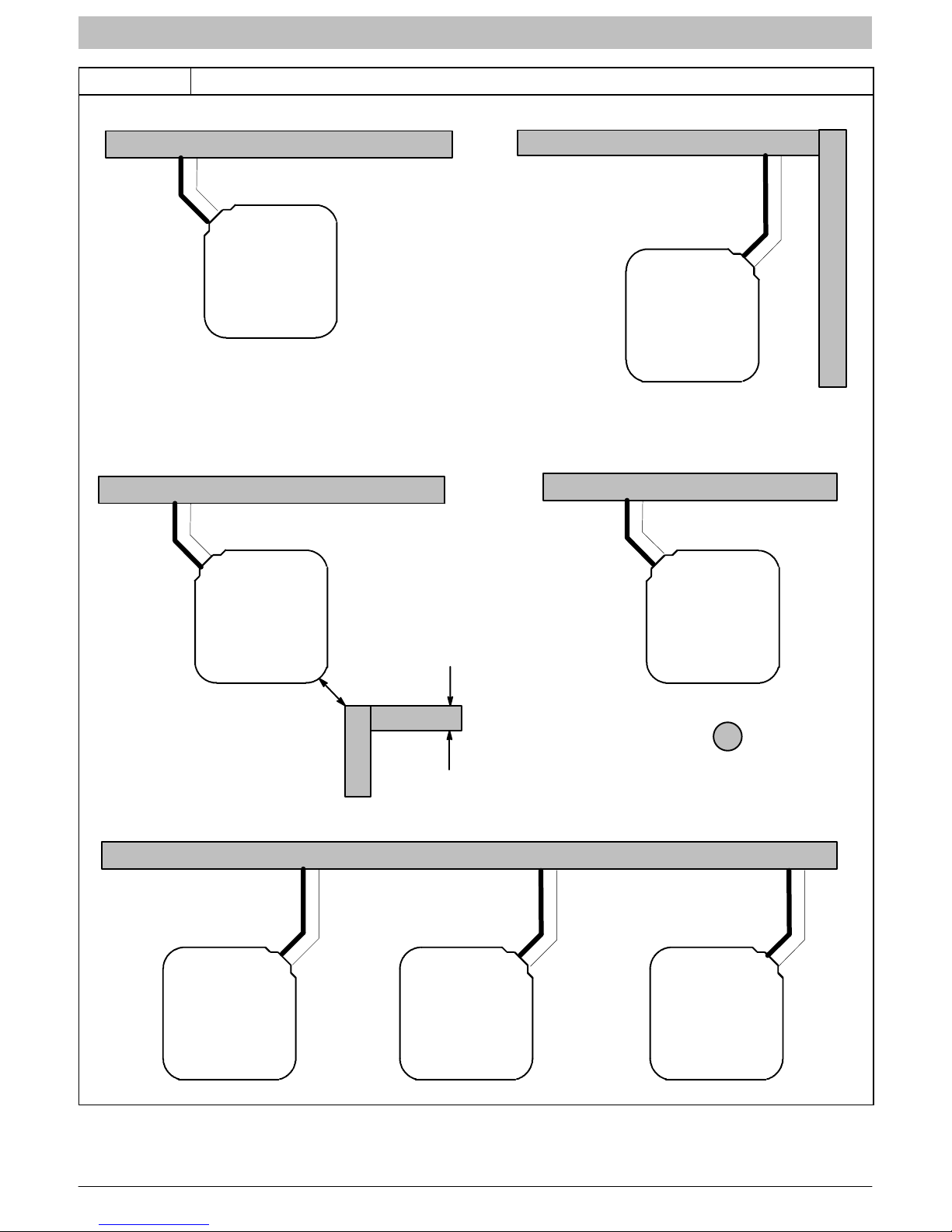
CLEARANCES
Nominal minimum clearances are 48 inches (1.2m)
above unit for discharge air and 18 inches (457mm) on
each side of the coil for intake air. Clearance on any one
side of the coil (normally between unit and structure) may
be reduced to 6 inches (152mm). Nominal minimum
clearances are based on a solid parallel object such as a
wall or roof overhang.
The clearance may be reduced for a single object with
small surface area, such as the end of a wall, outside
corner of a wall, fence section, post, etc. As a general
rule, the minimum clearance from the unit should equal
the width of the object. For example, a 6 inch (152mm)
fence post should be a minimum of 6 inches (152mm)
from the unit.
Locate unit away from recessed or confined areas where
recirculation of discharge air may occur (refer to
CLEARANCES section of this document).
Roof−top installation is acceptable providing the roof will
support the unit and provisions are made for water
drainage and noise/vibration dampening.
NOTE: Roof mounted units exposed to wind may require
wind baffles. Consult the manufacturer for additional
information.
Do not install unit under roof overhangs unless gutters
are present. A minimum vertical clearance of 48 inches
(1.2m) is required to the overhang.
Inside corner locations on single story structures require
evaluation. Large overhanging soffits may cause air
recirculation in a corner area even though recommended
minimum clearances are maintained. As a guide, locate
the unit far enough out so that half of the discharge grille
is out from under the soffit.
When placing two or more units side−by−side, provide a
minimum of 18 inches (457mm) between units.
Provide minimum service clearance of 24 inches
(610mm) from control box corner and side service panel.
Refer to Figure 1.
2 421 01 5103 00
Page 3
INSTALLATION INSTRUCTIONS R−410A Split System Air Conditioner
Figure 1 Clearances (various examples)
24”
(610mm)
Service
Wall
6”
(152mm)
18”
(457mm)
Wall
6”
(152mm)
18”
(457mm)
18”
(457mm)
Wall
24”
(610mm)
Service
Wall
6”
(152mm)
18”
(457mm)
Wall
6”
(152mm)
24”
(610mm)
Service
18”
(457mm)
24”
(610mm)
Service
4”
(102mm)
(457mm)
18”
(152mm)
18”
(102mm)
wide fence
Wall
24”
(610mm)
Service
4”
24”
(610mm)
Service
18”
(457mm)
18”
(457mm)
6”
(152mm)
6”
(152mm)
Post
24”
(610mm)
Service
18”
(457mm)
421 01 5103 00 3
Page 4
INSTALLATION INSTRUCTIONS R−410A Split System Air Conditioner
UNIT SUPPORT
NOTE: Unit must be level | 2 degrees {a inch rise or fall
per foot of run (10mm rise or fall per 305 mm of run) }or
compressor may not function properly.
A. GROUND LEVEL INSTALLATION
The unit must be level and supported above grade by
beams, platform, or a pad. Platform or pad can be of
open or solid construction but should be of permanent
materials such as concrete, bricks, blocks, steel, or
pressure− treated timbers approved for ground contact.
Soil conditions must be considered so that the platform
or pad does not shift or settle and leave the unit partially
supported. Minimum pad dimensions are shown in
Figure 2.
If beams or an open platform are used for support, it is
recommended that the soil be treated or area be
graveled to reduce the growth of grasses and weeds.
To minimize vibration or noise transmission, it is
recommended that supports not be in contact with the
building structure. However, slabs on grade
constructions with an extended pad are normally
acceptable.
B. ROOF TOP INSTALLATION
This type of installation is not recommended on wood
frame structures where low noise levels are required.
Supporting structure or platform for the unit must be
level. If installation is on a flat roof, locate unit minimum 6
inches (152mm) above roof level.
Place the unit over one or more load bearing walls. If
there are several units, mount them on platforms that are
self−supporting and span several load bearing walls.
These suggestions are to minimize noise and vibration
transmission through the structure. If the structure is a
home or apartment, avoid locating the unit over
bedrooms or study.
NOTE: When unit is to be installed on a bonded
guaranteed roof, a release must be obtained from the
building owner to free the installer from all liabilities.
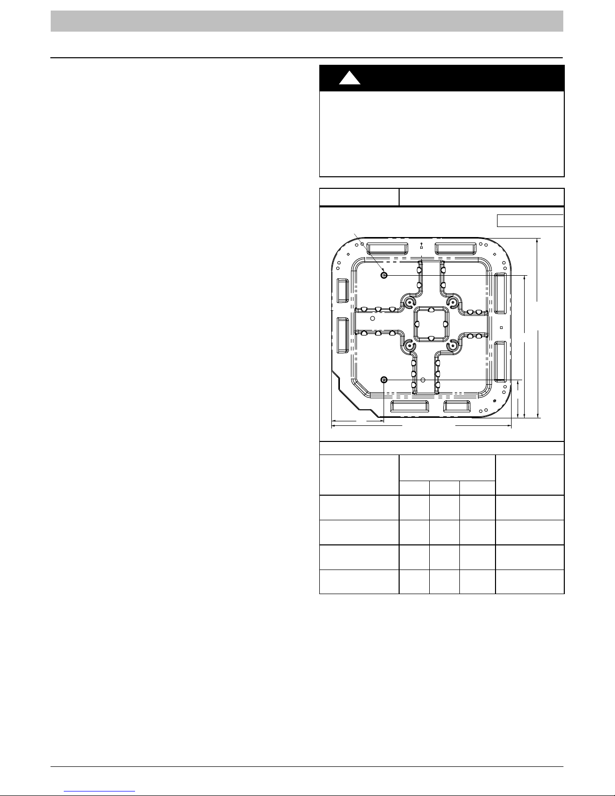
C. FASTENING UNIT DOWN
If conditions or local codes require the unit be attached in
place, remove the knockouts in the base pan and install
tie down bolts through the holes (refer to Figure 2).
Contact local distributor for hurricane hold−down details
and the P.E. (Professional Engineer) certification, when
required.
!
CAUTION
PROPERTY DAMAGE HAZARD
Failure to follow this caution may result in property damage.
Inadequate unit support may cause excessive
vibration, noise, and/or stress on the refrigerant
lines, leading to refrigerant line failure.
Figure 2 Tie Down Knockouts
a” (10mm) dia. Tie Down Knockouts
In Base Pan (2 places)
A
Base Pan Width
View From Top
Base
Pan
Depth
C
B
Inches (mm)
Base Pan
Width x Depth
@# ~ @#
(584 x 584)
@%n ~ @%n
(652 x 652)
#!8 ~ #!8
(791 x 791)
#$, ~ #$,
(887 x 887)
Tie Down
Knockouts
A B C
&w
(197)$v(113)!*(457)
(z
(230)$v(113)
(z
(230)^2(165)
(z
(230)^2(165)
@!4
(540)
@$s
(625)
@*v
(722)
Minimum
Mounting Pad
Dimensions
@# X~ @#
(584 x 584)
@^ X~ @^
(660 x 660)
#!2 ~ #!2
(800 x 800)
#% ~ #%
(889 x 889)
4 421 01 5103 00
Page 5
INSTALLATION INSTRUCTIONS R−410A Split System Air Conditioner
REFRIGERATION SYSTEM
A. COMPONENT MATCHES
Check to see that the proper system components are in
place, especially the indoor coil.
R−410A outdoor units can only be used with R−410A
specific indoor coils. If there is a refrigerant mis−match,
consult the indoor coil manufacturer to determine if a
refrigerant conversion kit is available for the indoor coil.
This outdoor unit is designed for use only with indoor
coils that utilize a TXV refrigerant metering device or
Piston with Teflon ring metering device. If any other type
of metering device is installed on the indoor coil, consult
the indoor coil manufacturer to determine if a TXV
conversion kit is available.
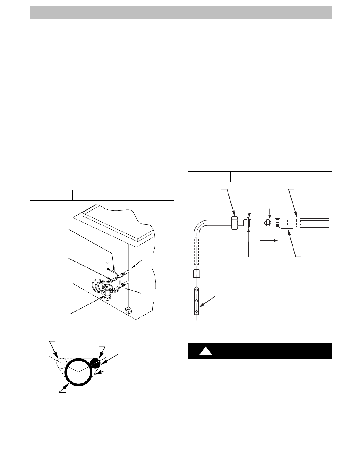
Installing with TXV
When installing a TXV on an indoor coil, follow the
instructions provided with the new TXV.
A typical TXV installation is shown in Figure 3.
Figure 3 Typical TXV Installation
Installing with Indoor Piston − cooling operation.
Check piston size shipped with indoor unit to see if it
matches required indoor piston size.
If it does not match, replace indoor piston with correct
piston size. (Indoor pistons are shipped with some
outdoor models in the accessory bag and are only
qualified for Piston fan coils.)
Example fan coils with piston: FEM4P, FSM4P, FSU4P
(12 thru 4 ton).
See Figure 4.
When changing indoor piston, use a back−up wrench.
Hand tighten hex nut, then tighten with wrench 1/2 turn.
Do not exceed 30 ft−lbs.The indoor piston contains a
Teflon ring (or seal) which is used to seat against the
inside of distributor body, and must be installed properly
to ensure proper seating in the direction for cooling
operation.
Figure 4 Indoor (cooling) Piston
BRASS
HEX NUT
TEFLON SEAL
TEFLON RING
DISTRIBUTOR
EQUALIZER
TUBE
SENSING
BULB
TXV
10 O’Clock
7/8
2 O’Clock
SUCTION TUBE
IN. OD & SMALLER
INDOOR
COIL
STRAP
SUCTION
TUBE
LIQUID
TUBE
SENSING BULB
PISTON
FLOW IN
COOLING
PISTON
RETAINER
STRAINER
BRASS
HEX BODY
L10S017
!
PRODUCT OPERATION HAZARD
Failure to follow this caution may result in improper product
operation.
If using a TXV in conjunction with a single−phase reciprocating compressor, a compressor start capacitor and relay are
required. Consult outdoor unit pre−sale literature for start assist kit part number.
CAUTION
421 01 5103 00 5
Page 6
INSTALLATION INSTRUCTIONS R−410A Split System Air Conditioner
B. REFRIGERANT LINE SETS
The refrigerant line set must be properly sized to assure
maximum efficiency and proper oil circulation.
Refer to Product Specifications and Long Line
Applications Guideline for line set sizing.
NOTE: Total line set length must not exceed 200 feet
(61m).
A crankcase heater must be used when the refrigerant
line length exceeds 80 feet (24.4m).
If outdoor unit is more than 10 feet (3m) higher than the
indoor coil, refer to the Long Line Applications Guideline
for instructions.
When the outdoor unit is higher than the indoor coil, the
vertical separation must not exceed 100 feet (30m).
When the outdoor unit is lower than the indoor coil, the
vertical separation must not exceed 50 feet (15.2m).
If it is necessary to add refrigerant line in the field, use
dehydrated or dry, sealed, deoxidized, copper
refrigeration tubing. Do not use copper water pipe.
Do not remove rubber plugs or caps from copper tubing
until connections are ready to be made.
Be extra careful when bending refrigeration tubing.
Tubing can “kink” easily, and if this occurs, the entire
length of tubing must be replaced.
!
WARNING
PERSONAL INJURY HAZARD
Failure to relieve system pressure could result in
personal injury and/or death.
Relieve pressure and recover all refrigerant before servicing existing equipment, and before final unit disposal. Use all service ports and open
all flow−control devices, including solenoid
valves.
C. ROUTING AND SUSPENDING REFRIGERANT
LINES
Run refrigerant lines as straight and direct as possible,
avoiding unnecessary bends and turns. Always insulate
the entire suction line. Both lines should be insulated
when routed through an attic or when routed through an
underground raceway.
When routing refrigerant lines through a foundation or wall,
do not allow refrigerant lines to come in direct contact with
the building structure. Make openings large enough so that
lines can be wrapped with extra insulation. Fill all gaps with
RTV caulk. This will prevent noise transmission between
the tubing and the foundation or wall.
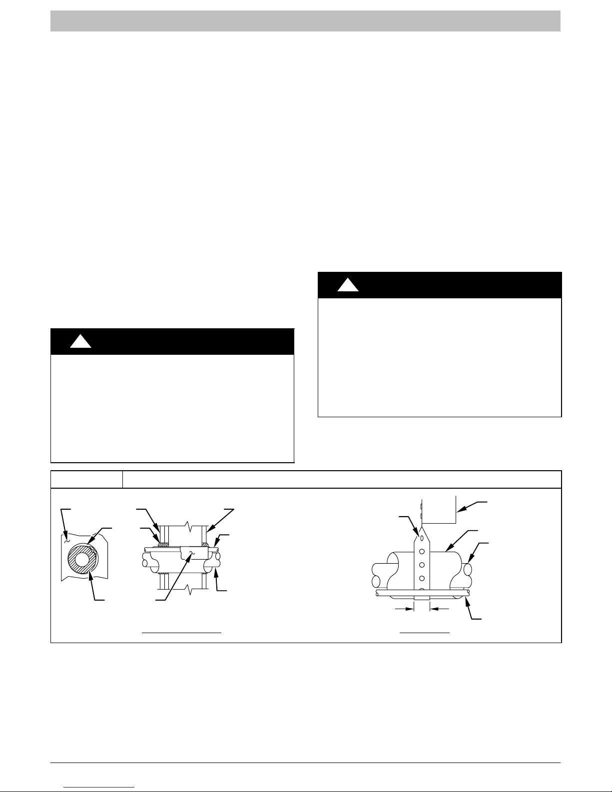
Along floor or ceiling joists, suspend refrigerant lines so
that they do not contact the building structure, water
pipes, or ductwork. Use insulated or suspension type
hangers. Metal straps must be at least 1” (25mm) wide to
avoid cutting into the tube insulation. Keep the liquid and
suction lines separate. Refer to Figure 5.
!
CAUTION
UNIT OPERATION HAZARD
Failure to follow this caution may result in improper product operation.
Do not leave system open to atmosphere any longer than absolutely required for installation. Internal system components − especially refrigerant
oils − are extremely susceptible to moisture contamination. Keep ends of tubing sealed during
installation until the last possible moment.
Figure 5 Routing and Suspending Refrigerant Lines
OUTDOOR WALL INDOOR WALL
CAULK
INSULATION
THROUGH THE WALL SUSPENSION
LIQUID TUBE
SUCTION TUBE
HANGER STRAP
(AROUND SUCTION
TUBE ONLY)
1” (25mm)
MIN
JOIST
INSULATION
SUCTION TUBE
LIQUID TUBE
6 421 01 5103 00
Page 7
INSTALLATION INSTRUCTIONS R−410A Split System Air Conditioner
refrigerant charge sealed in the unit. Leave the service
!
UNIT OPERATION HAZARD
Failure to follow this caution may result in improper product operation.
Do not bury more than 36” (1m) of line set underground. Refrigerant may migrate to cooler buried
section during extended periods of unit shut−
down, causing refrigerant slugging and possible
compressor damage at start−up.
If ANY section of the line set is buried underground, provide a minimum 6” (152mm) vertical
rise at the service valve.
D. OUTDOOR UNIT HIGHER THAN INDOOR UNIT
Proper oil return to the compressor should be maintained
with suction gas velocity. If velocities drop below 1500
fpm (feet per minute), oil return will be decreased. To
maintain suction gas velocity, do not upsize vertical
suction risers.
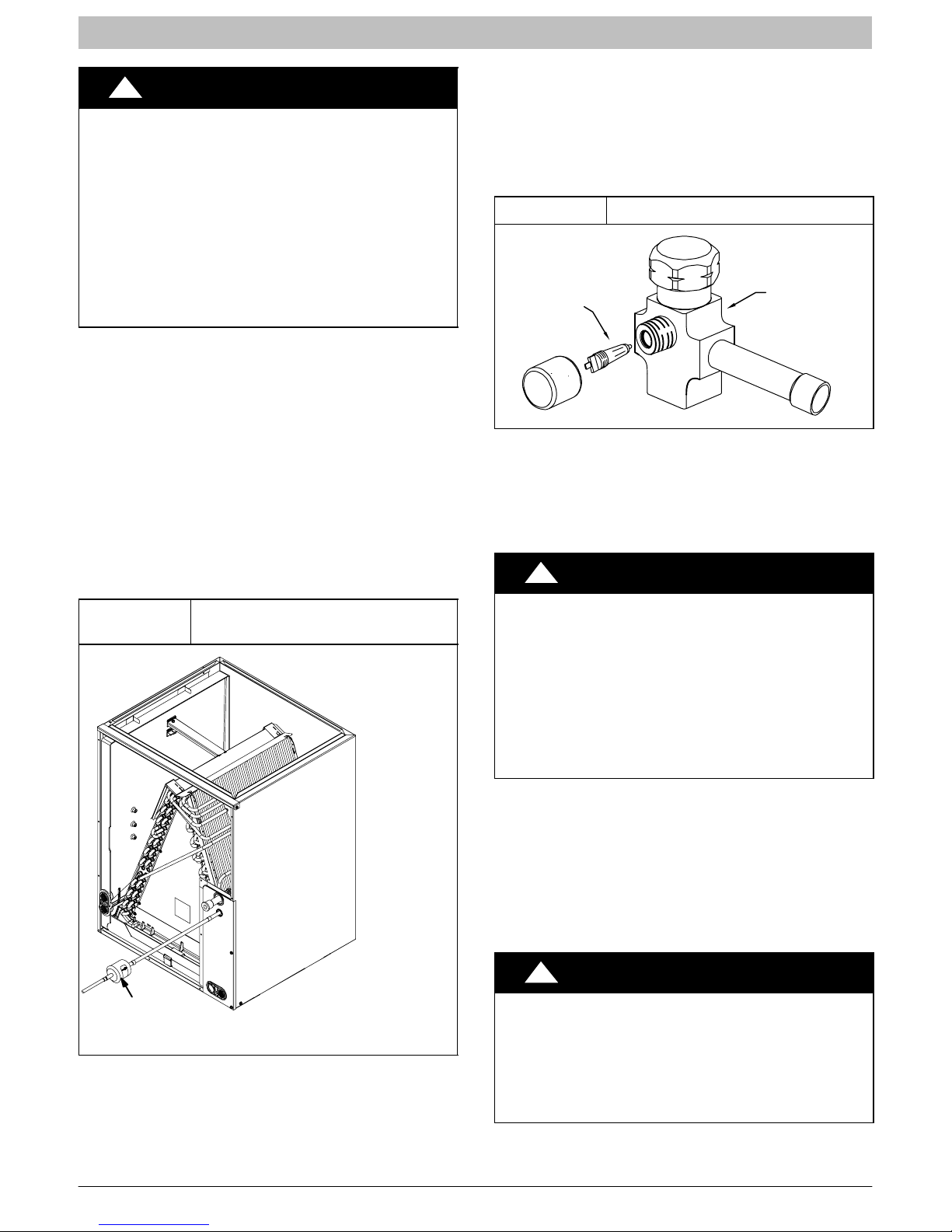
E. LIQUID LINE FILTER−DRIER
Outdoor units are shipped with an appropriate filter−drier
for installation in the liquid line. Leave the plugs in the
tube ends until the filter−drier is installed. The optimal
location for the filter−drier is close to the indoor coil.
Install the filter−drier with the arrow pointing towards the
indoor coil. Refer to Figure 6.
CAUTION
valves closed until all other refrigerant system work is
complete or the charge will be lost. Leave the plugs in
place until line set tubing is ready to be inserted.
Service valve bodies are brass and tube stubs are
copper.
Figure 7 Service Valve
VALVE CORE
G. BRAZING CONNECTIONS
NOTE: Remove valve core from schrader port on both
Service Valves BEFORE brazing. This helps prevent
overheating and damage to valve seals (refer to Figure 7).
Replace valve core when brazing is completed.
!
WARNING
SERVICE VALVE
Figure 6
Filter−Drier
(arrow points towards indoor coil)
F. SERVICE VALVES
Service valves are closed and tube stubs are plugged
from the factory. Outdoor units are shipped with a
Liquid Line Filter−Drier
Installed at Indoor Coil
38−11 −84
FIRE HAZARD
Failure to remove refrigerant and oil charge before brazing could result in personal injury, death,
and/or property damage.
Refrigerant and oil mixture could ignite and burn
as it escapes and contacts brazing torch. Make
sure the refrigerant charge is properly removed
from both the high and low sides of the system before brazing any component or lines.
Clean line set tube ends with emery cloth or steel brush.
Remove any grit or debris.
Insert line set tube ends into service valve tube stubs.
Apply heat absorbing paste or heat sink product between
service valve and joint. Wrap service valves with a heat
sinking material such as a wet cloth.
Braze joints using a Sil−Fos or Phos−copper alloy.
!
PRODUCT DAMAGE HAZARD
Failure to follow this caution may result in product damage.
Braze with Sil−Fos or Phos−copper alloy on copper−to−copper joints and wrap a wet cloth around
rear of fitting to prevent damage to TXV.
CAUTION
421 01 5103 00 7
Page 8
INSTALLATION INSTRUCTIONS R−410A Split System Air Conditioner
H. EVACUATING LINE SET AND INDOOR COIL
The unit is shipped with a factory refrigerant charge. The
liquid line and suction line service valves have been closed
after final testing at the factory. Do not disturb these valves
until the line set and indoor coil have been evacuated and
leak checked, or the charge in the unit may be lost.
NOTE: Do not use any portion of the factory charge for
purging or leak testing. The factory charge is for filling the
system only after a complete evacuation and leak check
has been performed.
!
CAUTION
PRODUCT DAMAGE HAZARD
Failure to follow this caution may result in product damage.
Never use the outdoor unit compressor as a vacuum pump. Doing so may damage the compressor.
Line set and indoor coil should be evacuated using the
recommended deep vacuum method of 500 microns. If
deep vacuum equipment is not available, the alternate
triple evacuation method may be used by following the
specified procedure.
If vacuum must be interrupted during the evacuation
procedure, always break vacuum with dry nitrogen.
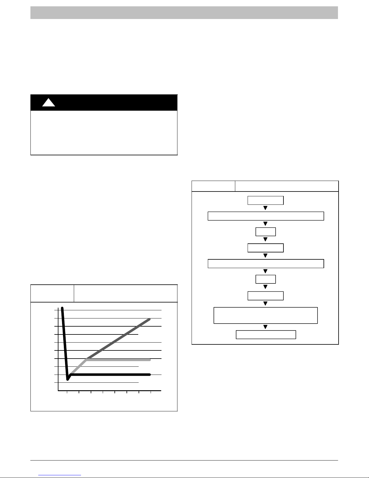
Deep Vacuum Method
The deep vacuum method requires a vacuum pump
capable of pulling a vacuum to 500 microns and a
vacuum gauge capable of accurately measuring this
vacuum level. The deep vacuum method is the most
positive way of assuring a system is free of air and water.
Watch the vacuum gauge as the system is pulling down.
The response of the gauge is an indicator of the condition
of the system (refer to Figure 8).
With no leaks in the system, allow the vacuum pump to
run for 30 minutes minimum at the deep vacuum level.
Triple Evacuation Method
The triple evacuation method should only be used when
system does not contain any water in liquid form and
vacuum pump is only capable of pulling down to 28 inches
of mercury (711mm Hg). Refer to Figure 9 and proceed as
follows:
1. Pull system down to 28 inches of mercury
(711mm Hg) and allow pump to continue
operating for an additional 15 minutes.
2. Close manifold valves or valve at vacuum pump
and shut off vacuum pump.
3. Connect a nitrogen cylinder and regulator to
system and fill with nitrogen until system pressure
is 2 psig.
4. Close nitrogen valve and allow system to stand for
1 hour. During this time, dry nitrogen will diffuse
throughout the system absorbing moisture.
5. Repeat this procedure as indicated in Figure 8.
6. After the final evacuate sequence, confirm there
are no leaks in the system. If a leak is found,
repeat the entire process after repair is made.
Figure 9 Triple Evacuation Sequence
EVACUATE
BREAK VACUUM WITH DRY NITROGEN
WAIT
EVACUATE
BREAK VACUUM WITH DRY NITROGEN
WAIT
Figure 8
5000
4500
4000
3500
3000
2500
2000
MICRONS
1500
1000
500
Deep Vacuum Gauge Response
and System Conditions
01
246
375
MINUTES
LEAK IN
SYSTEM
VACUUM TIGHT
TOO WET
TIGHT
DRY SYSTEM
EVACUATE
CHECK FOR TIGHT, DRY SYSTEM
(IF IT HOLDS DEEP VACUUM)
CHARGE SYSTEM
8 421 01 5103 00
Page 9

INSTALLATION INSTRUCTIONS R−410A Split System Air Conditioner
I. OPENING SERVICE VALVES
Outdoor units are shipped with a refrigerant charge
sealed in the unit. Opening the service valves releases
this charge into the system.
NOTE: Open the Suction service valve first. If the Liquid
service valve is opened first, oil from the compressor
may be drawn into the indoor coil TXV, restricting
refrigerant flow and affecting operation of the system.
Remove Suction service valve cap and insert a hex
wrench into the valve stem. Hold the valve body steady
with an end−wrench and back out the stem by turning the
hex wrench counterclockwise. Turn the stem until it just
contacts the rolled lip of the valve body.
After the refrigerant charge has bled into the system,
open the Liquid service valve.
NOTE: These are not back−seating valves. It is not
necessary to force the stem tightly against the rolled lip.
The service valve cap is a primary seal for the valve and
must be properly tightened to prevent leaks. Make sure
cap is clean and apply refrigerant oil to threads and
sealing surface on inside of cap.
Tighten cap finger tight and then tighten additional 6 of a
turn (1 wrench flat) to properly seat the sealing surfaces.
J. GAUGE PORTS
Check for leaks at the schrader ports and tighten valve
cores if necessary. Install plastic caps finger tight.
421 01 5103 00 9
Page 10
INSTALLATION INSTRUCTIONS R−410A Split System Air Conditioner
ELECTRICAL WIRING
Wiring Connections
!
ELECTRICAL SHOCK HAZARD
Failure to turn off the main (remote) electrical disconnect device could result in personal injury or
death.
Before installing, modifying or servicing system,
turn OFF the main (remote) electrical disconnect
device. There may be more than one disconnect
device.
The supply voltage must be 208/230 volts (197 volt
minimum to 253 volts maximum) 60 Hz single phase.
Outdoor units are approved for use with copper
conductors only. Do not use aluminum wire.
Refer to unit rating plate for minimum circuit ampacity
and circuit protection requirements.
Grounding
Permanently ground unit in accordance with the National
Electrical Code and local codes or ordinances. Use a
copper conductor of the correct size from the grounding
lug in control box to a grounded connection in the service
panel or a properly driven and electrically grounded
ground rod.
WARNING
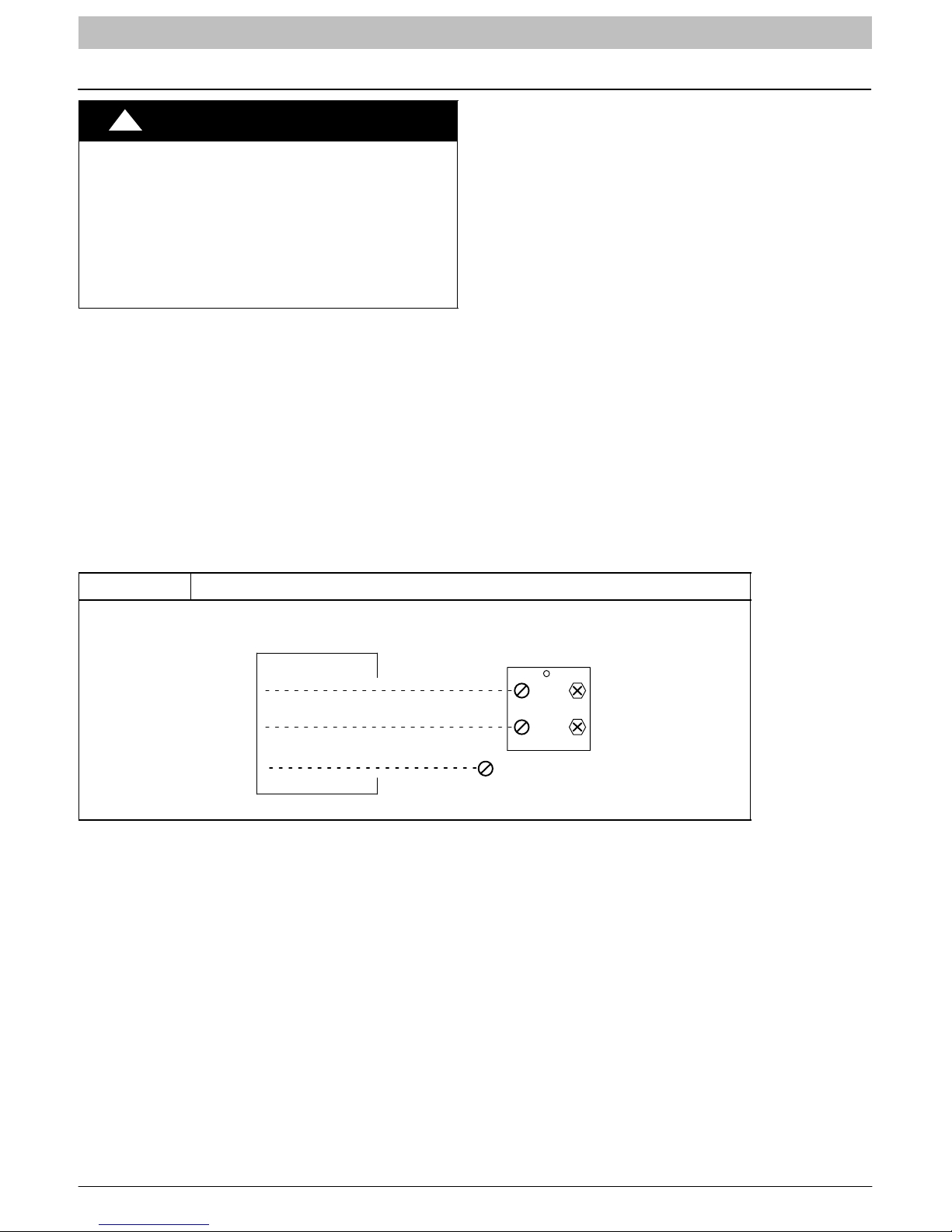
Make all outdoor electrical supply (Line Voltage)
connections with raintight conduit and fittings. Most
codes require a disconnect switch outdoors within sight
of the unit. Consult local codes for special requirements.
Route electrical supply (Line Voltage) wiring through
knockout hole in bottom of Control Box. Connect wires to
Contactor and Ground Lug according to Wiring Diagram
on unit. Refer to Figure 10.
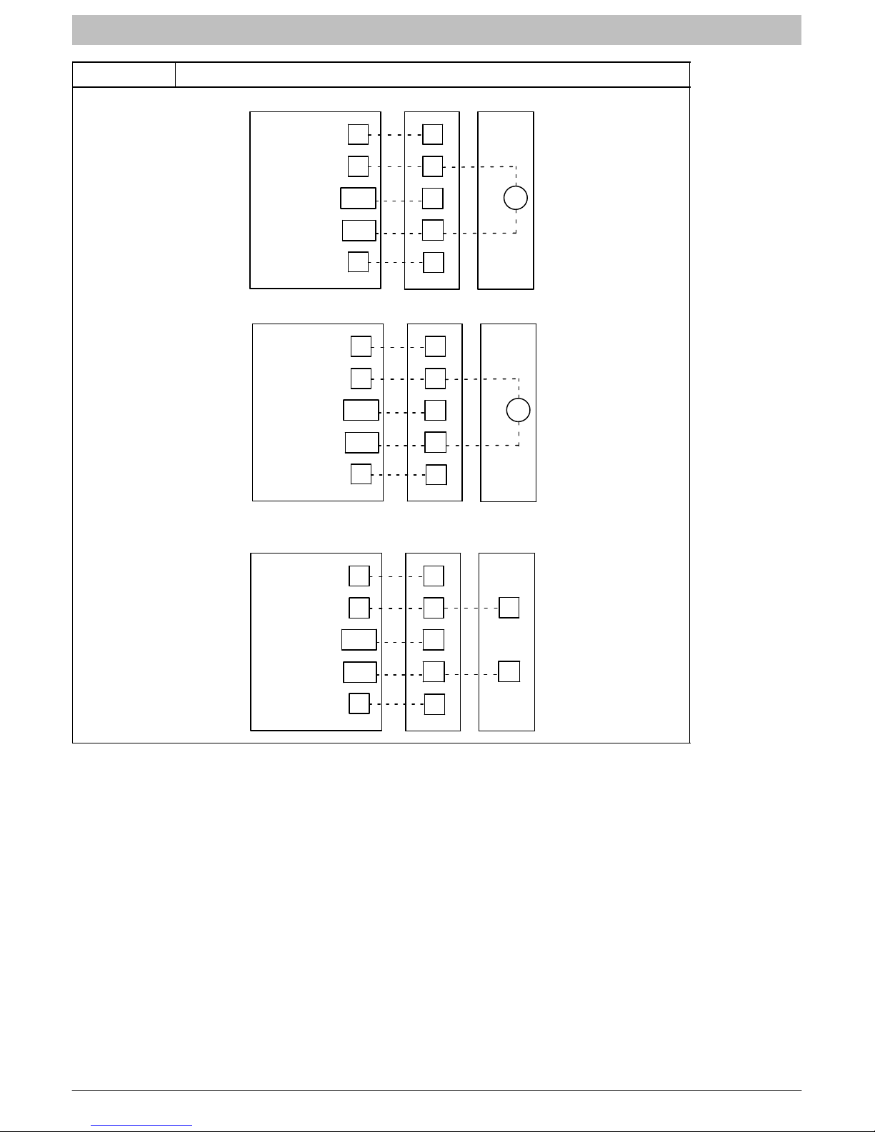
Route thermostat wiring through rubber grommet in
bottom of Control Box. Low voltage lead wires are
provided in the control box for connection to thermostat
wires (use wire nuts). Refer to Wiring Diagram on unit
and Figure 11 for low voltage wiring examples.
NOTE: Use No. 18 AWG (American Wire Gage)
color−coded, insulated (35 ° C minimum) wire. If
thermostat is located more than 100 feet (31 m) from unit
as measured along the control voltage wires, use No. 16
AWG color−coded wires to avoid excessive voltage
drop.
NOTE: Some models are factory equipped with Comfort
Alertt Diagnostics device. If Comfort Alert is used as a
field installed option, then a hot bundle must be run for
proper connection.
Figure 10 Electrical Supply (Line Voltage) Connections
DISCONNECT
PER NEC AND/OR
LOCAL CODES
CONTACTOR
11
23 or 13
LUG
FIELD POWER
WIRING
FIELD GROUND
WIRING
L1
L2
GROUND
10 421 01 5103 00
Page 11
INSTALLATION INSTRUCTIONS R−410A Split System Air Conditioner
Figure 11 Typical Thermostat Connections
THERMOSTAT FURNACE
24 VAC HOT
24 VAC COM
COOL STAGE 1
INDOOR FAN
THERMOSTAT FAN COIL
24 VAC HOT
24 VAC COM
COOL STAGE 1
INDOOR FAN
R
C
W/W1
Y/Y2
G
R
C
W/W1
Y/Y2
G
R
C
WHEAT STAGE 1
Y
G
R
C
W2HEAT STAGE 1
Y
G
AIR CONDITIONER
C
AIR CONDITIONER
C
THERMOSTAT FAN COIL
24 VAC HOT
24 VAC COM
HEAT STAGE 1
COOL STAGE 1
INDOOR FAN
R
C
W/W1
Y/Y2
G
R
C
W2
Y
G
AC with Comfort Alert
C
Y
421 01 5103 00 11
Page 12
INSTALLATION INSTRUCTIONS R−410A Split System Air Conditioner
START−UP PROCEDURE
1. Set indoor thermostat selector switch to OFF.
2. Turn ON all electrical disconnect devices.
3. If unit has a crankcase heater, energize the heater
and wait 24 hours before proceeding.
REFRIGERANT CHARGE
Factory charge amount and desired subcooling are
shown on unit rating plate. Charging method is shown on
information plate inside unit.
For TXV, use subcooling method.
For Piston, use superheat method.
To properly check or adjust charge, conditions must be
favorable for subcooling or superheat charging.
Favorable conditions exist when the outdoor
temperature is between 70_F and 100_F (21_C and
38_C), and the indoor temperature is between 70_F and
80_F (21_C and 27_C). Follow the procedure below.
Unit is factory charged for 15 feet (4.6m) of lineset.
Adjust charge by adding or removing 0.6 oz/ft (17 g/mm)
of 3/8 liquid line above or below 15 feet (4.6 m)
respectively.
For standard refrigerant line lengths 80 feet (24.4m) or
less, allow system to operate in cooling mode at least 15
minutes. If conditions are favorable, check system
charge by super heat method for fixed metering device
and subcooling method for TXV. If any adjustment is
necessary, adjust charge slowly and allow system to
operate for 15 minutes to stabilize before declaring a
properly charged system.
4. Set indoor thermostat at desired temperature. Be
sure setpoint is below indoor ambient temperature
or thermostat will not call for cooling.
5. Set indoor thermostat selector switch to COOL.
Operate unit for minimum 15 minutes, then check
the system refrigerant charge.
If the indoor temperature is above 80_F (27_C), and the
outdoor temperature is in the favorable range, adjust
system charge by weight based on line length and allow
the indoor temperature to drop to 80_F (27_C) before
attempting to check system charge by subcooling
method as described above.
If the indoor temperature is below 70_F (21_C), or the
outdoor temperature is not in the favorable range, adjust
charge for line set length above or below 15 feet (4.6m)
only. Charge level should then be appropriate for the
system to achieve rated capacity. The charge level could
then be checked at another time when the both indoor
and outdoor temperatures are in a more favorable range.
NOTE: If line length is beyond 80 feet (24.4m) or greater
than 20 feet (6.1m) vertical separation, See Long Line
Guideline for special charging requirements.
12 421 01 5103 00
Page 13

INSTALLATION INSTRUCTIONS R−410A Split System Air Conditioner
A. UNITS WITH COOLING MODE TXV
Units installed with cooling mode TXV require charging
by the subcooling method.
1. Operate unit a minimum of 15 minutes before
checking charge.
2. Measure liquid service valve pressure by
attaching an accurate gage to service port.
3. Measure liquid line temperature by attaching an
accurate thermistor type or electronic
thermometer to liquid line near outdoor coil.
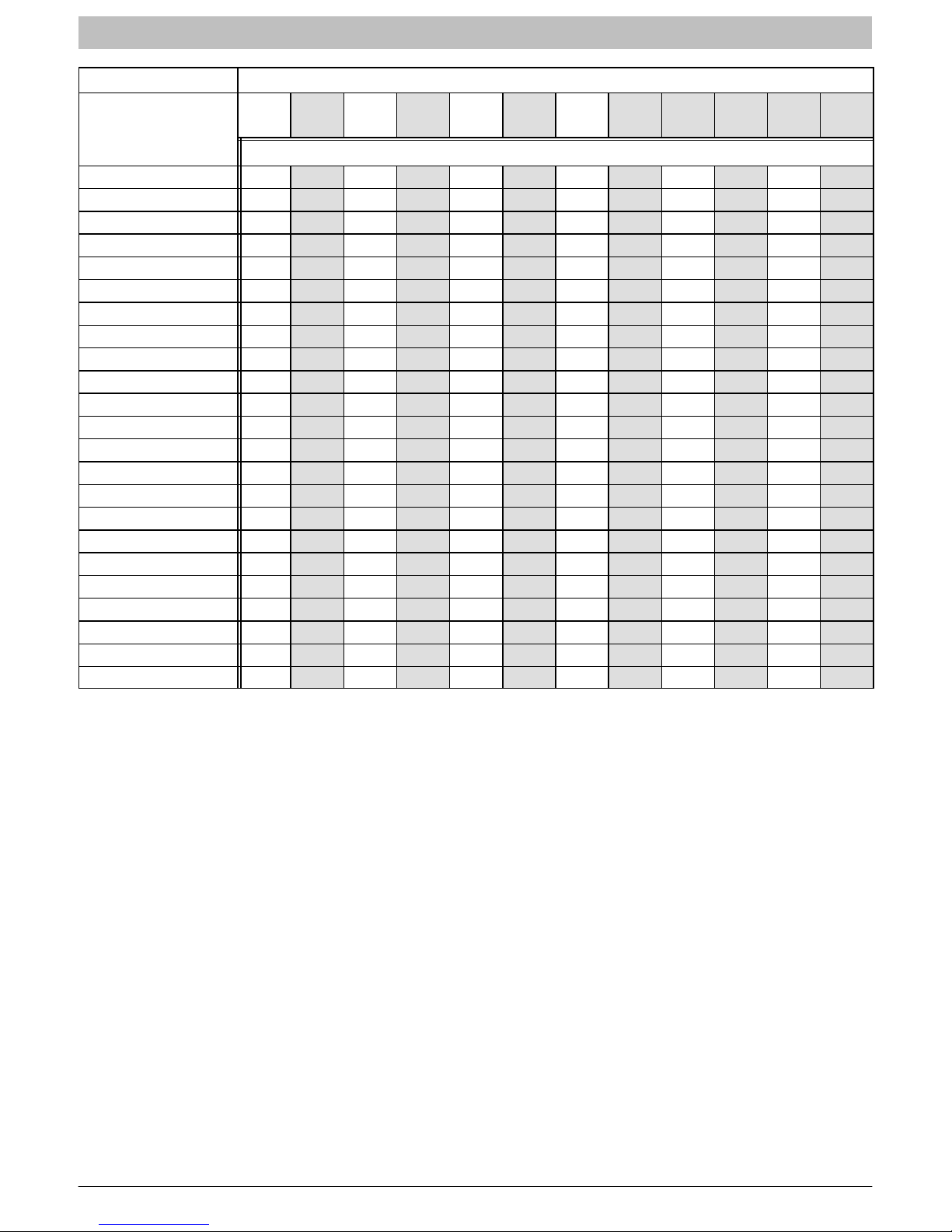
4. Refer to unit rating plate for required subcooling
temperature.
5. Refer to Figure 14. Find the point where required
subcooling temperature intersects measured
liquid service valve pressure.
6. To obtain required subcooling temperature at a
specific liquid line pressure, add refrigerant if
liquid line temperature is higher than indicated or
reclaim refrigerant if temperature is lower. Allow a
tolerance of "3_F (|1.7_C).
B. UNITS WITH INDOOR PISTON
Units installed with indoor pistons require charging by the
superheat method.
The following procedure is valid when indoor airflow is
within "21 percent of its rated CFM.
1. Operate unit a minimum of 15 minutes before
checking charge.
2. Measure suction pressure by attaching an
accurate gage to suction valve service port.
3. Measure suction temperature by attaching an
accurate thermistor type or electronic
thermometer to suction line at service valve.
4. Measure outdoor air dry−bulb temperature with
thermometer.
5. Measure indoor air (entering indoor coil) wet−bulb
temperature with a sling psychrometer.
6. Refer to Figure 12. Find outdoor temperature and
evaporator entering air wet−bulb temperature. At
this intersection, note superheat. Where a dash
(−−) appears on the table, do not attempt to
charge system under these conditions or
refrigerant slugging may occur. Charge must be
weighted in, adding or removing 0.6 oz/ft of 3/8
liquid line above or below 15 feet (4.6m)
respectively.
7. Refer to Figure 13. Find superheat temperature
(from #6 above) and suction pressure. At this
intersection, note suction line temperature.
8. If unit has a higher suction line temperature than
charted temperature, add refrigerant until charted
temperature is reached.
9. If unit has a lower suction line temperature than
charted temperature, reclaim refrigerant until
charted temperature is reached.
10. When adding refrigerant, charge in liquid form into
suction service port using a flow−restricting
device.
11. If outdoor air temperature or pressure at suction
valve changes, charge to new suction line
temperature indicated on chart.
12. Optimum performance will be achieved when
the operating charge produces 10_F suction
superheat at suction service valve with 95_F
(35_C) outdoor ambient and 80_F (27_C) dry
bulb (67_F / 19_C) wet bulb) indoor
temperature (DOE “A” test conditions) at
rated airflow.
421 01 5103 00 13
Page 14

INSTALLATION INSTRUCTIONS R−410A Split System Air Conditioner
Figure 12 Superheat Charging − AC Only
OUTDOOR TEMP (_F)
55 9 12 14 17 20 23 26 29 32 35 37 40 42 45
60 7 10 12 15 18 21 24 27 30 33 35 38 40 43
65
70
75
80
85
90
95
100
105
110
115
*Optimum performance point, 95°F (35°C) outdoor ambient and (80°F / 27°C dry bulb), (67°F / 19°C wet bulb) indoor conditions. (DOE A Test Conditions)
Where a dash (--) appears do not attempt to charge system under these conditions or refrigerant slugging may occur. Charge must be weighed in.
Note: Superheat °F is at low-side service port, Allow a tolerance of ± 3°F (± 1.7°C)
Note: Indoor dry bulb between 70°F and 80°F (21°C and 27°C)
50 52 54 56 58 60 62 64 67 68 70 72 74 76
—
6 10 13 16 19 21 24 27 30 33 36 38 41
— —
— — —
— — — —
— — — — — —
— — — — — —
— — — — — — —
— — — — — — — —
— — — — — — — —
— — — — — — — — —
— — — — — — — — — —
EVAPORATOR ENTERING AIR TEMPERATURE (_F WB)
7 10 13 16 19 21 24 27 30 33 36 39
6 9 12 15 18 21 24 28 31 34 37
5 8 12 15 18 21 25 28 31 35
8 11 15 19 22 26 30 33
5 9 13 16 20 24 27 31
6 10 14 18 22 25 29
8 12 15 20 23 27
5 9 13 17 22 26
6 11 15 20 25
8 14 18 23
Figure 13 Required Suction−Line Temperature
SUPERHEAT TEMP (_F)
0 35 37 39 41 43 45 47 49 51
2 37 39 41 43 45 47 49 51 53
4 39 41 43 45 47 49 51 53 55
6 41 43 45 47 49 51 53 55 57
8 43 45 47 49 51 53 55 57 59
10 45 47 49 51 53 55 57 59 61
12 47 49 51 53 55 57 59 61 63
14 49 51 53 55 57 59 61 63 65
16 51 53 55 57 59 61 63 65 67
18 53 55 57 59 61 63 65 67 69
20 55 57 59 61 63 65 67 69 71
22 57 59 61 63 65 67 69 71 73
24 59 61 63 65 67 69 71 73 75
26 61 63 65 67 69 71 73 75 77
28 63 65 67 69 71 73 75 77 79
30 65 67 69 71 73 75 77 79 81
32 67 69 71 73 75 77 79 81 83
34 69 71 73 75 77 79 81 83 85
36 71 73 75 77 79 81 83 85 87
38 73 75 77 79 81 83 85 87 89
40 75 77 79 81 83 85 87 89 91
107.8 112.2 116.8 121.2 126 130.8 138.8 140.8 145.8
SUCTION PRESSURE AT SERVICE PORT (PSIG)
14 421 01 5103 00
Page 15
INSTALLATION INSTRUCTIONS R−410A Split System Air Conditioner
Figure 14 Rating Plate (required) Subcooling Temperature ° F (° C)
° F (° C) ° F (° C) ° F (° C) ° F (° C) F (° C) F (° C)
Measured Liquid
6 3 8 4 10 6 12 7 14 8 16 9
Pressure (psig)
R−410A Required Liquid Line Temperature ° F (° C)
251 78 26 76 24 74 23 72 22 70 21 68 20
259 80 27 78 26 76 24 74 23 72 22 70 21
266 82 28 80 27 78 26 76 24 74 23 72 22
274 84 29 82 28 80 27 78 26 76 24 74 23
283 86 30 84 29 82 28 80 27 78 26 76 24
291 88 31 86 30 84 29 82 28 80 27 78 26
299 90 32 88 31 86 30 84 29 82 28 80 27
308 92 33 90 32 88 31 86 30 84 29 82 28
317 94 34 92 33 90 32 88 31 86 30 84 29
326 96 36 94 34 92 33 90 32 88 31 86 30
335 98 37 96 36 94 34 92 33 90 32 88 31
345 100 38 98 37 96 36 94 34 92 33 90 32
364 104 40 102 39 100 38 98 37 96 36 94 34
374 106 41 104 40 102 39 100 38 98 37 96 36
384 108 42 106 41 104 40 102 39 100 38 98 37
395 110 43 108 42 106 41 104 40 102 39 100 38
406 112 44 110 43 108 42 106 41 104 40 102 39
416 114 46 112 44 11 0 43 108 42 106 41 104 40
427 116 47 114 46 11 2 44 110 43 108 42 106 41
439 118 48 116 47 11 4 46 112 44 11 0 43 108 42
450 120 49 118 48 11 6 47 114 46 11 2 44 110 43
462 122 50 120 49 118 48 116 47 114 46 11 2 44
474 124 51 122 50 120 49 11 8 48 11 6 47 114 46
421 01 5103 00 15
Page 16
INSTALLATION INSTRUCTIONS R−410A Split System Air Conditioner
SEQUENCE OF OPERATION
With power supplied to indoor and outdoor units,
transformer is energized.
On a call for cooling, the thermostat makes circuits R−Y
and R−G. Circuit R−Y energizes contactor, starting
outdoor fan motor and compressor. Circuit R−G
energizes indoor unit blower relay, starting indoor blower
motor.
TROUBLESHOOTING
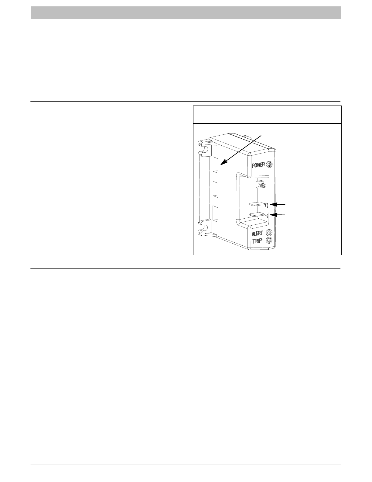
Some models are factory equipped with the Comfort
Alertt Diagnostics device in the control box (refer to
Figure 15). Comfort Alert provides around−the−clock
monitoring for common electrical problems, compressor
defects, and broad system faults. If trouble is detected,
an alert code is displayed with a flashing LED indicator.
Alert codes are listed in Figure 16.
The device is factory wired and requires no
modification. Low voltage lead wires are provided in the
control box for connection to thermostat wires (use wire
nuts).
The Comfort Alert device operates by monitoring the
compressor power leads and the thermostat demand
signal (Y terminal).
When thermostat is satisfied, its contacts open,
de−energizing contactor and blower relay. Compressor
and motors stop.
NOTE: If indoor unit is equipped with a time−delay relay
circuit, the blower runs an additional length of time to
increase system efficiency.
Figure 15
Comfort Alertt Diagnostics
(some models)
Compressor Wires
Pass Through Holes (3)
24 VAC Common
Thermostat Demand
MAINTENANCE
Condensate Drain
During the cooling season, check monthly for free flow of
drainage and clean if necessary.
Cleanliness
These tips will help keep the air conditioner looking better
and working more efficiently:
1. Free flow of air is essential. Keep fences, shrubs,
trash cans, and other obstructions at least 18
inches (457mm) from all coil inlets.
2. Keep the coil free of grass clippings, leaves,
weeds, and other debris.
NOTE: Coil may occasionally require cleaning
with a liquid solution. The coil must be cold when
cleaning. Use an alkaline based cleaner only.
Cleaning a hot coil or using an acid based cleaner
will remove the paint from the fins and may clog
the coil.
3. Never use a weather cover over the outdoor unit
unless it is a ventilated type or made of breathable
fabric that will allow moisture to evaporate rapidly.
A cover that holds moisture in the unit will cause
more rust build−up and damage than normal
exposure to weather.
16 421 01 5103 00
Page 17
INSTALLATION INSTRUCTIONS R−410A Split System Air Conditioner
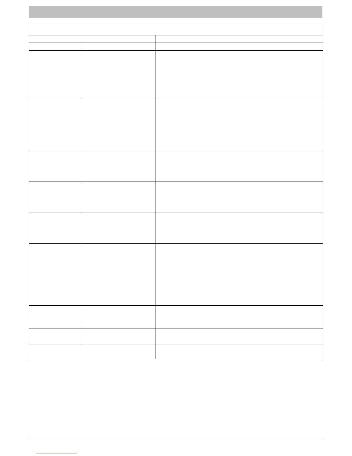
Figure 16 Comfort Alertt Diagnostics (some models)
Status LED Status LED Description Status LED Troubleshooting Information
Green “POWER” Module has power Supply voltage is present at module terminals
Red “TRIP” Thermostat demand signal
Y1 is present, but the
compressor is not running
1. Compressor protector is open
2. Outdoor unit power disconnect is open
3. Compressor circuit breaker or fuse(s) is open
4. Broken wire or connector is not making contact
5. Low pressure switch open if present in system
6. Compressor contactor has failed open
Yellow “ALERT”
Flash Code 1
Long Run Time
Compressor is running
extremely long run cycles
1. Low refrigerant charge
2. Evaporator blower is not running
3. Evaporator coil is frozen
4. Faulty metering device
5. Condenser coil is dirty
6. Liquid line restriction (filter drier blocked if present in system)
7. Thermostat is malfunctioning
Yellow “ALERT”
Flash Code 2
Yellow “ALERT”
Flash Code 3
System Pressure Trip
Discharge or suction
pressure out of limits or
compressor overloaded
Short Cycling
Compressor is running
only briefly
1. High head pressure
2. Condenser coil poor air circulation (dirty, blocked, damaged)
3. Condenser fan is not running
4. Return air duct has substantial leakage
1. If high pressure switch open, go to Flash Code 2 information
2. If low pressure switch open, go to Flash Code 1 information
3. Thermostat demand signal is intermittent
4. Loose wiring at contactor coil
Yellow “ALERT”
Flash Code 4
Locked Rotor
1. Run capacitor has failed
2. Low line voltage (contact utility if voltage at disconnect is low)
3. Excessive liquid refrigerant in compressor
4. Compressor bearings are seized
Yellow “ALERT”
Flash Code 5
Open Circuit
1. Outdoor unit power disconnect is open
2. Compressor circuit breaker or fuse(s) is open
3. Compressor contactor has failed open
4. High pressure switch is open and requires manual reset
5. Open circuit in compressor supply wiring or connections
6. Unusually long compressor protector reset time due to
extreme ambient temperature
7. Compressor windings are damaged
Yellow “ALERT”
Flash Code 6
Open Start Circuit
Current only in run circuit
1. Run capacitor has failed
2. Open circuit in compressor start wiring or connections
3. Compressor start winding is damaged
Yellow “ALERT”
Flash Code 7
Yellow “ALERT”
Flash Code 9
Open Run Circuit
Current only in start circuit
Low Voltage
Control circuit < 17VAC
1. Open circuit in compressor run wiring or connections
2. Compressor run winding is damaged
1. Control circuit transformer is overloaded
2. Low line voltage (contact utility if voltage at disconnect is low)
S Flash Code number corresponds to a number of LED flashes, followed by a pause and then repeated.
S TRIP and ALERT LEDs flashing at same time means control circuit voltage is too low for operation.
421 01 5103 00 17
Page 18
INSTALLATION INSTRUCTIONS R−410A Split System Air Conditioner
R−410A QUICK REFERENCE GUIDE
• R−410A refrigerant operates at 50% − 70% higher pressures than R−22. Be sure that servicing equipment and
replacement components are designed to operate with R−410A.
• R−410A refrigerant cylinders are rose colored.
• Recovery cylinder service pressure rating must be 400 psig, DOT 4BA400 or DOT BW400.
• R−410A systems should be charged with liquid refrigerant. Use a commercial type metering device in the
manifold hose.
• Manifold sets should be 750 psig high−side and 200 psig low−side with 520 psig low−side retard.
• Use hoses with 750 psig service pressure rating.
• Leak detectors should be designed to detect HFC refrigerant.
• R−410A, as with other HFC refrigerants, is only compatible with POE oils.
• Vacuum pumps will not remove moisture from oil.
• Do not use liquid line filter−driers with rated working pressures less than 600 psig.
• Do not install a suction line filter−drier in liquid line.
• POE oils absorb moisture rapidly. Do not expose oil to atmosphere.
• POE oils may cause damage to certain plastics and roofing materials.
• Wrap all filter−driers and service valves with wet cloth when brazing.
• A liquid line filter−drier is required on every unit.
• Do not use with an R−22 TXV.
• If indoor unit is equipped with an R−22 TXV, it must be changed to an R−410A TXV.
• Never open system to atmosphere while it is under a vacuum.
• When system must be opened for service, break vacuum with dry nitrogen and replace all filter−driers.
• Do not vent R−410A into the atmosphere.
• Do not use capillary tube indoor coils.
• Observe all WARNINGS, CAUTIONS, NOTES, and bold text.
18 421 01 5103 00
International Comfort Products, LLC
Lewisburg, TN 37091 USA
 Loading...