

CALsys 1200
CALsys 1200
Dry block Temperature Calibrator
USER MANUAL
TEMPSENS INSTRUM ENT (I) PVT. LTD UNIT II

1. General Instruction........................................................................1
1.1 Information on operating instruction
1.2 Liability & warranty
1.3 Unpacking & initial inspection
2 Before you start.............................................................................2
2.1 Safety information
2.2 Warning
2.3 Caution
3 Technical Data................................................................................3
3.1 Technical specification
3.2 Circuit diagram
4 Overview........................................................................................4
4.1 Introduction
4.2 Outline description
5. Operating Instruction.....................................................................5
5.1 Power
5.2 Setting the temperature
5.3 Operating Instruction
6. Operation of Controller...................................................................6
6.1 The Temperature Controller
6.2 Altering the set point
6.3 Monitoring the Controlling Status
6.4 Units
7. Maintenance & Trouble shooting.....................................................7
7.1 Maintenance
7.2 Troubleshooting
8. Software Installation......................................................................8
8.1 Installation
8.2 Par a m e t e r i n mai n screen
1. General Instruction
1.1 Information on operating instruction
Congratulations on your purchase of high-quality and efficient CALsys 1200 temperature
calibrator.Read this manual carefully to all instructions on safety, operation and maintenance. It
serves as an important source of information and reference for installation and operation of the
device. The general safety requirements must be strictly adhered to when operating the
device. The fact contained especially safety are observed. If you experience any further
questions, please contact our technical support by phone or mail to tech@tempsens.com
1.2 Liability and warranty
This instrument has been manufactured to exacting standards and is warranted for twelve
months against electrical breakdown or mechanical failure caused through defective material or
workmanship, provided the failure is not the result of misuse. In the event of failure covered
by this warranty, the instrument must be returned, carriage paid, to the supplier for
examination and will be replaced or repaired at our option.
I NT ERFERENCE W I T H O R F AILURE T O P R O P E R L Y MAINTAIN T H I S I N S T R U M E N T MAY
I N V A L I D THIS WARRANT Y .
1.3 Unpacking & Initial Inspection
Our packing department uses custom designed packaging to send out your unit, but as
accidents can still happen in transit, you are advised, after unpacking the unit, to inspect it for
any sign of damage, and confirm that your delivery is in accordance with the packing note. If
you find any damage or find any part missing during delivery notify us and the carrier
immediately. If the unit is damaged you should keep the packing for possible insurance
assessment.
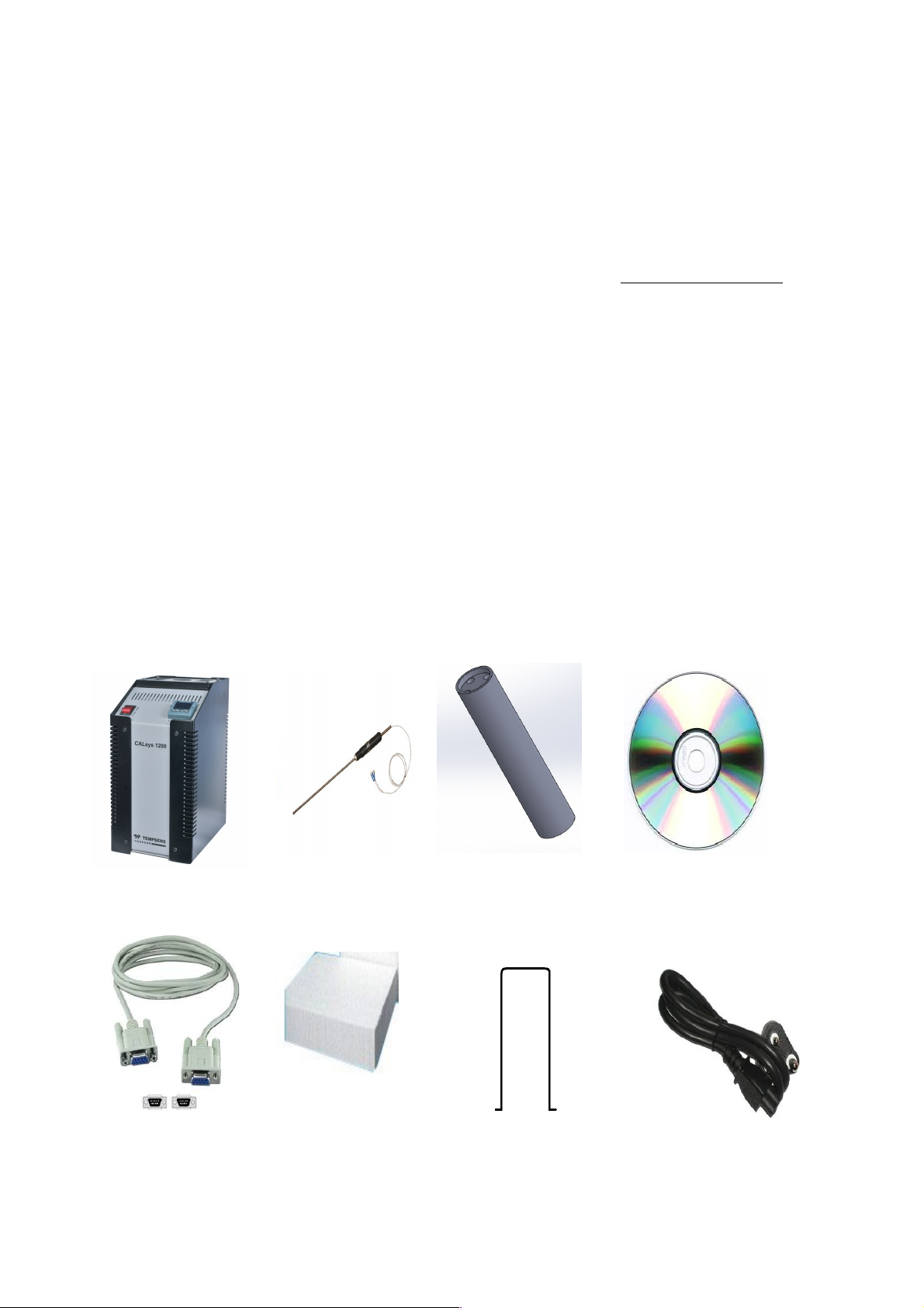
After unpacking yo u w i l l f i n d f o l l o w in g i tems.
Calsys 1200 N type TC I n c o n e l B l o c k Software CD
RS-232 cable Insulation wool Tongue Tool Po wer cable
(Block remove r )

2.
Before you Start
2.1 Safety Information
Use the instrument only as specified in this manual. Otherwise, the protection provided by the
instrument may be impaired. Refer to the safety information below and throughout the manual.
The following definitions apply to the terms “Warning” and “Caution”.
“Warning” identifies conditions and actions that may pose hazards to the user.
“Caution” identi fies conditions and a ctions that may da m a g e t h e i n s t r u m e n t
being used.
2.2 Warning
To avoid possible electric shock or personal injury, follow these guidelines.
This equipment must be correctly earthed.
A protective earth is used to ensure the conductive parts can not become live in the event of
a failure of the insulation.
The protective conductor of the flexible mains cable which is colored green/yellow MUST be
connected to a suitable earth.
Warning: Internal mains voltage hazard. Do not remove the panels.
There are no user serviceable parts inside. Contact us for repair.
Do not use the apparatus outside its recommended range i.e., + 250 to 1200° C.
Ensure inflammable materials, are kept away from hot parts of the apparatus, to prevent
fire risk.
Before connecting to the electricity supply, please familiarize yourself with the parts of the
calibrator with the help of operating manual.
BURN HAZARD – Do not touch the target surface of the unit.
Always replace the fuse with one of the same rating, voltage and type.
Overhead clearance is required. Do not place unit under a cabinet or other structure.
Do not use this unit for any application other than calibration work.
Completely u n a t t e n d e d h i g h t e m p e r a t u r e o p e r ation i s n o t r e c o m m e n d e d f o r
safety reasons.
CALIBRAT I O N E Q U I PEMENT should only be use d by TRAINED PERSONNE L .
We a r a p p r o p r i a t e p r o t e c ti ve clothing.
2.3 Caution
To avoid possible damage to the instrument, follow these guidelines.
Components and heater lifetime can be shortened by continuous high temperature
operation.
Do n o t c h a n g e t h e v a l u e s o f t h e c a l i b r a t i o n c o n s t a n t s f r o m t h e factory set
values. T he c o r r e c t s e tting o f t h e s e parameters i s i m p o r t a n t t o t h e s a f e t y
and proper opera t i o n o f t h e c a l i b rator.

3. Technical Data
3.1 Technical Specifi c a t i o n
Voltage 230 V AC
Power 1.5 KW
Supply Frequency 50/60 Hz
Temperature range 250 to 1200°C
Resolution 0.1 °C
Stability ± 0.5 °C
Controlling sensor R type T/C
Time to reach max. Temperature 90 Min.
Operating Temperature 20 to 45 °C
Controller Specifications Eurotherm
Stabilization Time 15 to 20 Min.
Dimensions 405 (H) x 205 (W) x 285 (D) mm
Block 2X6.0 mm, 2x8.0 mm
Weight Approx 14 kg
3.2Circuit Diagram

4. Overview
4.1 Introduction:
The ‘CALsys 1200’ has been designed to provide stable and accurate temperature to enable
professionals to calibrate Temperature Sensing Devices by comparison method. The
‘CALsys 1200’ model has been designed to be rugged and easily maintained. This model
provides an isothermal enclosure (Metal block) in which the thermocouple/RTD can be
calibrated against the temperature of the calibrator. For traceable calibration a master
calibration sensor should be placed into the metal block alongside the unit under calibration.
The method is widely accepted because the calibrator provides very stable temperature
nearing to its controlled point, the Master Thermocouple / RTD, which is calibrated by
independent Laboratory traceable to National standards, compares the sensor under
calibration.
The ‘CALsys’ models are part of wide range of portable calibrators designed and made by us.
Please contact us in case you required more information about our other products.
4.2 Outline Description:
‘The calibrator controller uses a precision R type thermocouple as a controlling sensor and
controls the well temperature with Kanthal spiral heater. To obtain and maintain a required
temperature the controller varies the power to the heater via solid-state relay. There is one
electricity driven fan which is situated under the heating chamber for cooling the heater. The
CALsys 1200 dry block calibrator was designed for portability, moderate cost and ease of
operation. With proper use the instrument should provide continued accurate calibration of
temperature sensors and devices. The user should be familiar with the safety guidelines and
operating procedures of the calibrator as described in the User’s Manual.
5. Operating Instruction
(1) PID Controller
(2) ON/OFF switch of heater
(3) Power cable
(4) RS-232 output

5.1 Power
Place the calibrator on a flat surface with at least 6 inches of free space around the instrument.
Overhead clearance is required. Do not place under a cabinet or structure. Insert equilizing block
into the well with help of tong, after inserting remove the tong from equalizing block. Plug the
power cord into mains outlet of the proper voltage, frequency Typically this will be (230 VAC ±10,
50/60 Hz). Turn the “Mains” (Heater) switch located on front panel. The controller dispaly should
illuminate after 3-4 sec . After a brief self test the controller should begin normal operation. If the
unit fails to operate please check the power connection.
5.2 Setting the Temperature
Press “UP” or “DOWN” buttons to change the change the temperature set-point value. When the
set-point temperature is changed the controller will switch the CALsys 1200 ON or OFF to raise or
lower the temperature. The displayed temperature will gradually change until it reaches the setpoint
temperature. The temperature bath requires 15 to 20 minutes to reach the set-point depending on
the span. Another 10 to 15 minutes is required to stabilize the temperature bath within ± 0.5ºC of
the set-point.
5.3 Operating Instruction:-
1. Insert the inconel block into well of furnace.
2. Connect the ‘CALsys 1200’ to a suitable power supply & Switch ON the Dry bath source and set
the desire temperature value in PID by using UP & Down key.
3. Insert the reference (Master) temperature sensor and UUC (Unit under calibration) into the
thermowell (inconel block).
4. PV (Present value) display in controller will gradually rise until it reaches the set point
temperature. The controller takes some times to reach the set-point depending on the span.
Furnace is stable when PV is equal to SV (Set Value).
5. Master sensor take some times to reach the setpoint temperature and stable at temperature
near about controller set temperature.
6. When temperature of the master and UUC (Unit under calibration) are stable record the
readings of master sensor.
7. Compare the UUC reading with the master’s reading & find out the error by comparison method.
8. Reset the controller and / or repeat the calibration for another calibration point or for another
sensor.
9. When the calibration is complete, reset the controller to 0°C & wait until the unit has cooled to
below 100°C, before moving the ‘CALsys 1200 to new location the ‘CALsys 1200’ must be cooled
below 100°C before it can be put back into its carrying case.

6. Operation of Controller
FRONT PANEL LAYOUT
Operator Buttons
6.1 The Temperature Controller
The controller has a dual display, the upper display indicates the measured temperature, and
the lower display indicates the desired temperature or set point.
6.2 Altering the Set point
To change the set point of the controller use the UP and DOWN keys to raise and lower the set
point to the required value. The lower display changes to indicate the new set point.
6.3 Monitoring the Controller Status
A row indicate the controllers status as follows
OP1 Heat Output
OP2 Cool Output
REM This beacon indicates activity on the PC interface
ALM this indicates when PV (Present value) is more than 1200°C.
6.4 Units
Momentary pressing of the Scroll key will show the controller units °C or °F by using SCROLL
key & UP & DOWN key unit can be change.
IMPORTANT NOTICE
The controller's function settings are preset and will not require adjustment. Use
only up & down key.

7. Maintenance & Trouble shooting
7.1 Maintenance
The calibration instrument has been designed with the utmost care. Ease of operation and
simplicity of maintenance have been a central theme in the product development.
Therefore, with proper care the instrument should require very little maintenance. Avoid
operating the instrument in an oily, wet, dirty, or dusty environment.
If the outside of the instrument becomes soiled, it may be wiped clean with a damp cloth
and mild detergent. Do not use harsh chemicals on the surface which may damage the
paint.
Avoid knocking or dropping the calibrator.
If the mains supply cord becomes damaged, replace it with a cord with the appropriate
gauge wire for the current of the instrument.
Depending on the environment in which it is used, periodic cleaning is recommended.
Cleaning may be accomplished by the use of a small dry paint brush.
7.2 Trouble shooting
1. Unit fails to operate
Check fuse if it is tripped switch is ON. If not power ON of calsys 1200 bath consult us.
2. Unit unstable
Controller parameter has been interfered, consult us.
3. If the temperature of the calibrator is not rising
(a) The heating element may be open.
(b) The thermocouple may be open.
(c) The SSR may be damaged.
(d) The controller may not be giving output
(e) The ambient temperature inside the chamber is raised and safety controller switched
OFF the power
CAUTIONARY NOTE
TEMPSENS PRODUCTS ARE INTENDED FOR USE BY TECHNICALLY TRAINED AND COMPETENT
PERSONNEL FAMILIAR WITH GOOD MEASUREMENT PRACTICES.
IT IS EXPECTED THAT PERSONNEL USING THIS EQUIPMENT WILL BE COMPETENT WITH THE
MANAGEMENT OF APPARATUS WHICH MAY BE POWERED OR UNDER EXTREMES OF
TEMPERATURE, AND ARE ABLE TO APPRECIATE THE HAZARDS WHICH MAY BE ASSOCIATED
WITH, AND THE PRECAUTIONS TO BE TAKEN WITH, SUCH EQUIPMENT.

8. Software Installation
The provided Tempsens software offers possibilities toconnect furnace temperature bath and
change set point,maximum time span, view real time graph andevaluate measuring data.
1.1 Installation
Install the calibration software using the installation guide file on CD ROM. After installation of
the software; Double click the application. It willopen the screen of software.
1.2 Parameter in mainscreen
1.2.1 Communication
Communication between the furnace and the software is implemented via a RS-232 cable
connected between the furnace and the PC serial port. This enables the acquisition and
recording of data, as well as the transfer of commands from the software application to the
Tempsens furnace. Communication can be done by clicking on connect and select correct COM
port address (fig. 1) where furnace is connected. Also user has to select type of controller
version3216 (fig. 2). Then click on CONNECT button. Shown com2 connected successfully.

1.2.2 Scale Trend: -in scale trend you have to change the Y-Axis Min value 0 and Y-AxisMax
value 1200.MaximumTime Span, Minutes have to save data the data logging up to 120
minutes, than clickon start graph button. After complete the task clickon save to file button.
Set Point (°C): - in which you can set temperature of furnace as your requirement.
PVI Value: - Read the current PVvalue (present value of furnace temperature).
File will be stored in .xls formatto save previous recordopen the file by clicking on menu file
open.

Safety Instructions:
Do's and Don'ts -
*Keep switch off the red ON / OFF switch at furnace front after switch off the power
supply when furnace not in use.
*Don't remove power cable when furnace is ON.
* Keep cover the block with ceremic wool after insertion sensor for proper insulation.
*Keep down the furnace when not in use before switch off the furnace.
*Don't touch the surface hot part when temperature is high or furnace is in use.
*Don't drop any liquid solution or water upon the furnace.
*Keep place block safely when furnace is OFF.
*Contact our person for any help.
Information
Packing Instruction
To transport or store the instrument, please use the original box or a box padded with
sufficient shock absorbing material. For storage in humid areas or shipment overseas, the
device should be placed in welded foil ( ideally along with silicon gel) to protect it from
humidity.
Warranty
TEMPSENS CALsys 1200 instrument have a warranty of one year from the invoice date. This
warranty covers manufacturing defects. User induced faults are not covered under this
warranty.
Limit of Liability
TEMPSENS not liable for any damages that arise from the use of any examples or processes
mentioned in this
Specifications are subject to change without notice
Copyright:@ 2009, TEMPSENS. All right
This document may contain proprietary information and shall be respected as a
proprietary document to TEMPSENS with permission for review and usage given only to the rightful
owner of the equipment with which this document is associated.
TEMPSENS reserves the right to make changes, without further notice, to any product
herein to improve reliability, function, or design . TEMPSENS does not assume any liability arising out of
the application or use of any product described herein, neither does it convey any license under its patent
right nor the right of others.
Copyright:@2009

TEMPSENS INSTRUMENT (I) PVT. LTD
 Loading...