

USER MANUAL
EN
ITAG®4 / ITAG®4 Bio/ ITAG®4 TH DATA LOGGER
UM-ITAG4-160217 REV.B
Updated@ 03/02/2016

UM-ITAG4-160217 REV.B
CONTENTS
Product Overview .............................................................................................................................................. 3
Logger ........................................................................................................................................................ 3
LCD ............................................................................................................................................................ 4
Technical Specifications..................................................................................................................................... 5
TEMPCENTRE SOFTWARE ............................................................................................................................. 6
How to download TempCentre software?................................................................................................... 6
Installing and using TempCentre software ................................................................................................. 6
Data Logger Configuration ................................................................................................................................ 7
Configuring Logger with TempCentre ......................................................................................................... 7
Configuring Loggers Online ........................................................................................................................ 7
Applying Configuration ............................................................................................................................... 8
Configuration Options ................................................................................................................................. 8
Recording ......................................................................................................................................................... 11
Start Recording .......................................................................................................................................... 11
In Recording ............................................................................................................................................. 12
Stopping recording ................................................................................................................................... 14
Downloading Data ........................................................................................................................................... 15
Downloading Data by Obtaining PDF Report ........................................................................................... 15
Downloading Data via TempCentre .......................................................................................................... 16
Data Results Explanation ................................................................................................................................ 16
Device Information.................................................................................................................................... 16
Logging Summary .................................................................................................................................... 16
Alarms ...................................................................................................................................................... 16
Battery.............................................................................................................................................................. 18
Shelf Life / Expiry Date ............................................................................................................................. 18
Error Codes ..................................................................................................................................................... 19
MKT ................................................................................................................................................................. 19
Why is MKT important in the life of pharmaceuticals and perishable goods?.......................................... 19
Additional Information ...................................................................................................................................... 20
Glossary ........................................................................................................................................................... 21
Warranty .......................................................................................................................................................... 22
Revision History ............................................................................................................................................... 23
UM-ITAG4-160217 REV.B
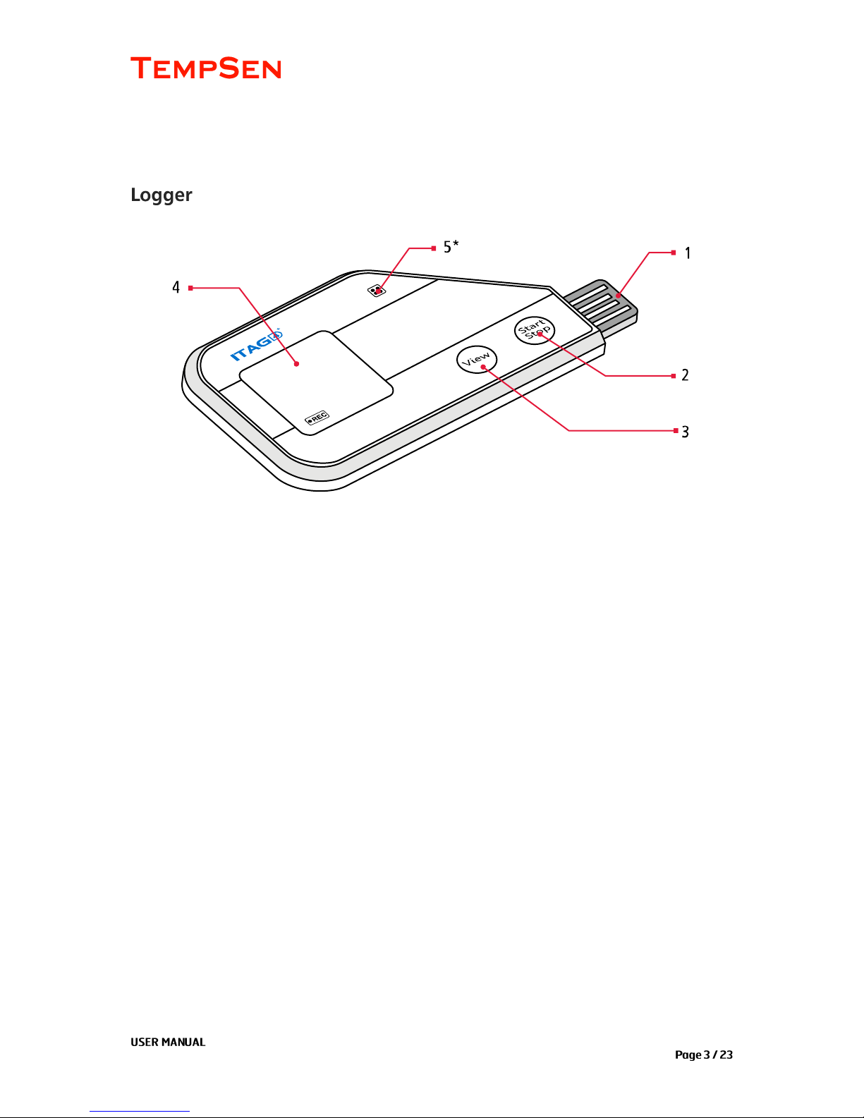
PRODUCT OVERVIEW
1. USB Plug
2. Start and Stop Button
3. View Button
4. LCD
5. *Humidity sensor window, only available on ITAG4 TH
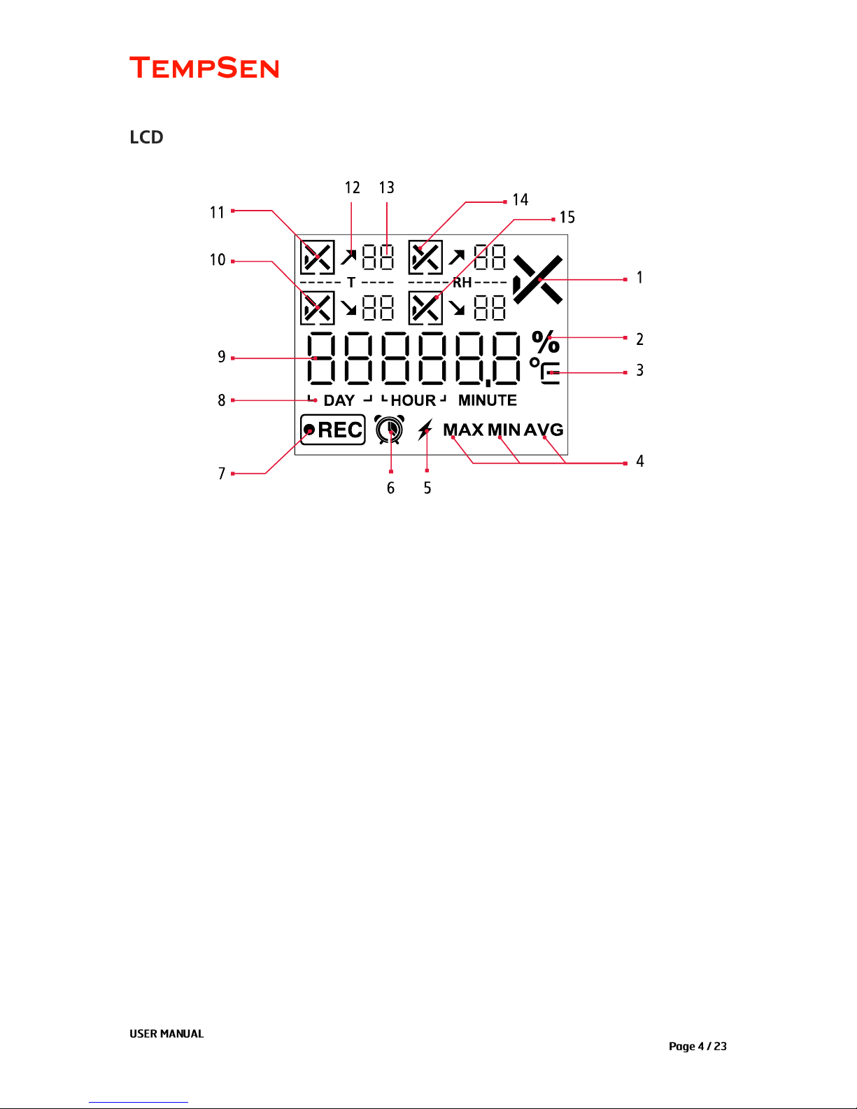
UM-ITAG4-160217 REV.B
1. Overall alarm status
2. Relative humidity unit*
3. Temperature unit (Celsius and Fahrenheit)
4. Maximum, minimum, average
5. Power active indicator
6. Start timer and limit violation duration indicators
7. Recording indicator
8. Time units
9. Readings
10. Low alarm zone status (temperature sensor)
11. High alarm zone (temperature sensor)
12. Limit violation indicator
13. Number of limit violation events
14. High alarm zone (humidity sensor)*
15. Low alarm zone status (humidity sensor)*
*Applicable on ITAG4 TH
UM-ITAG4-160217 REV.B
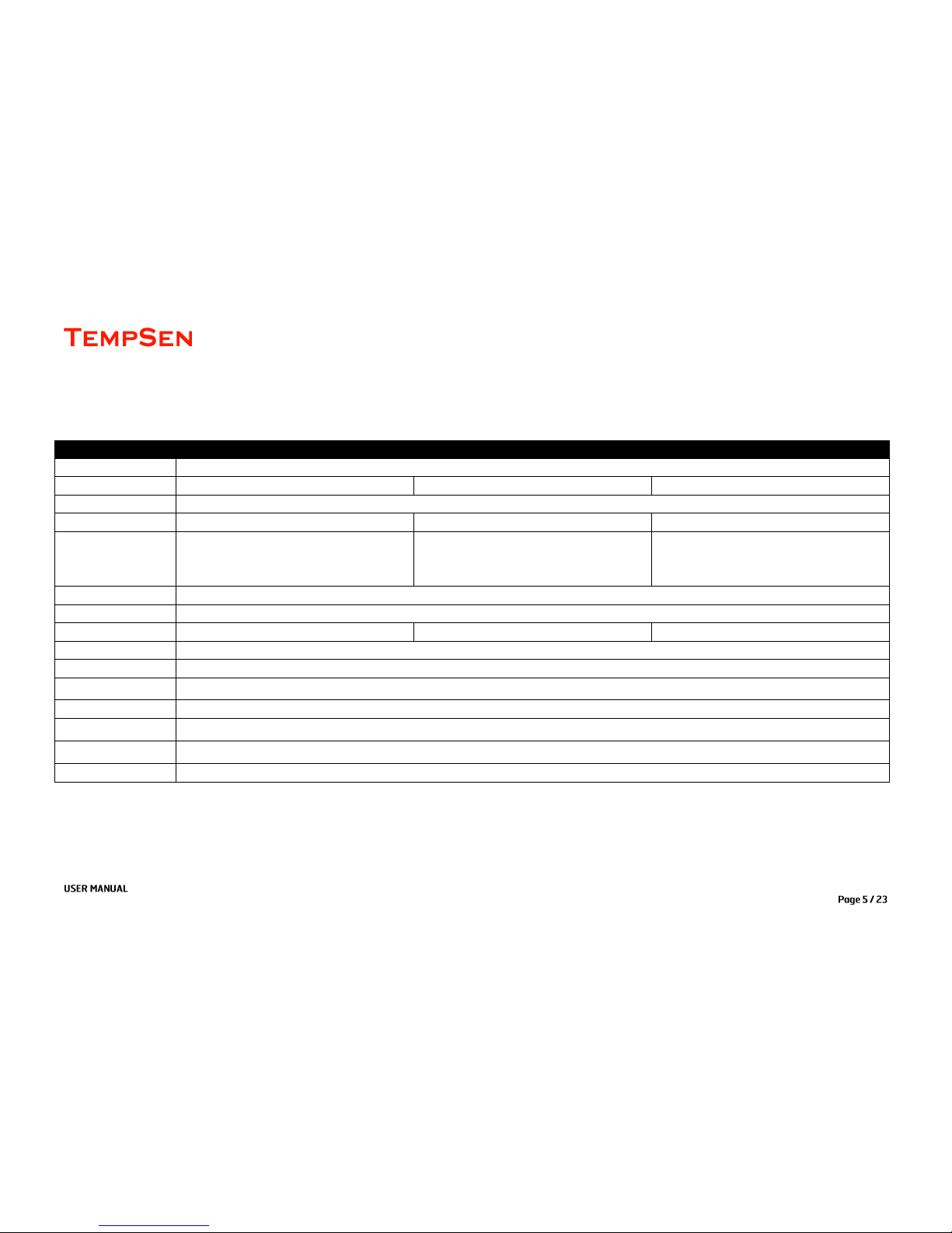
TECHNICAL SPECIFICATIONS
Product
ITAG4
ITAG4 Bio
ITAG4 TH
Type
Single Use
Sensor
Internal NTC
Internal NTC
Internal temperature and humidity Sensor
Memory Capacity
7200 readings
Measurement Range
-30°C...70°C (-22°F...158°F)
-30°C...70°C (-22°F...158°F)
-30°C...70°C, 0% RH...100% RH
Accuracy
±0.5°C/0.9°F
±0.5°C/0.9°F
± 0.5°C (0°C…60°), ± 1°C (rest range)
±4% RH (20% RH...80% RH)
Resolution
0.1°C /°F
Logging Interval
1 minute...2 hours
Alarm Range
High and low alarm
High and low alarm/5 alarm ranges
High and low alarm
Battery
CR2032 lithium battery
Typical Run Time
60 days max
Shelf Life
2 years (1 year if power activated)
Automatic Data File
Encrypted PDF report with embedded raw data
Dimensions
93mm L x 45mm W x 7mm H
Weight
Approx. 25g
Protection Class
IP65
UM-ITAG4-160217 REV.B
TEMPCENTRE SOFTWARE
Please download and install the latest version of TempCentre software from www.tempsen.com.
If it’s your first time to download software from www.tempsen.com, please sign up with the information
required prior to downloading, then an email containing download link would be sent to the mail address
you left in couple of minutes.
If you want to download the software from www.tempsen.com again after your successful registration
last time, please click “I already signed up, download now” button in dialog box, then software would
begin to download in couple of minutes.
Please refer to TempCentre User Manual for installation and operation instructions of TempCentre software.
UM-ITAG4-160217 REV.B
DATA LOGGER CONFIGURATION
Connect ITAG4 data logger to USB port of PC, open TempCentre software, select Configure Device in tool
bar, software would automatically start searching and connecting devices, then user could start programming
of this data logger.
Connect ITAG4 logger to USB port of PC, open Internet Browser, go to www.itag4.com, input and select
configuration parameters you need, then download the configuration profile (.cfg format file), save it into the
logger created removable storage device “TempSenDisk”.
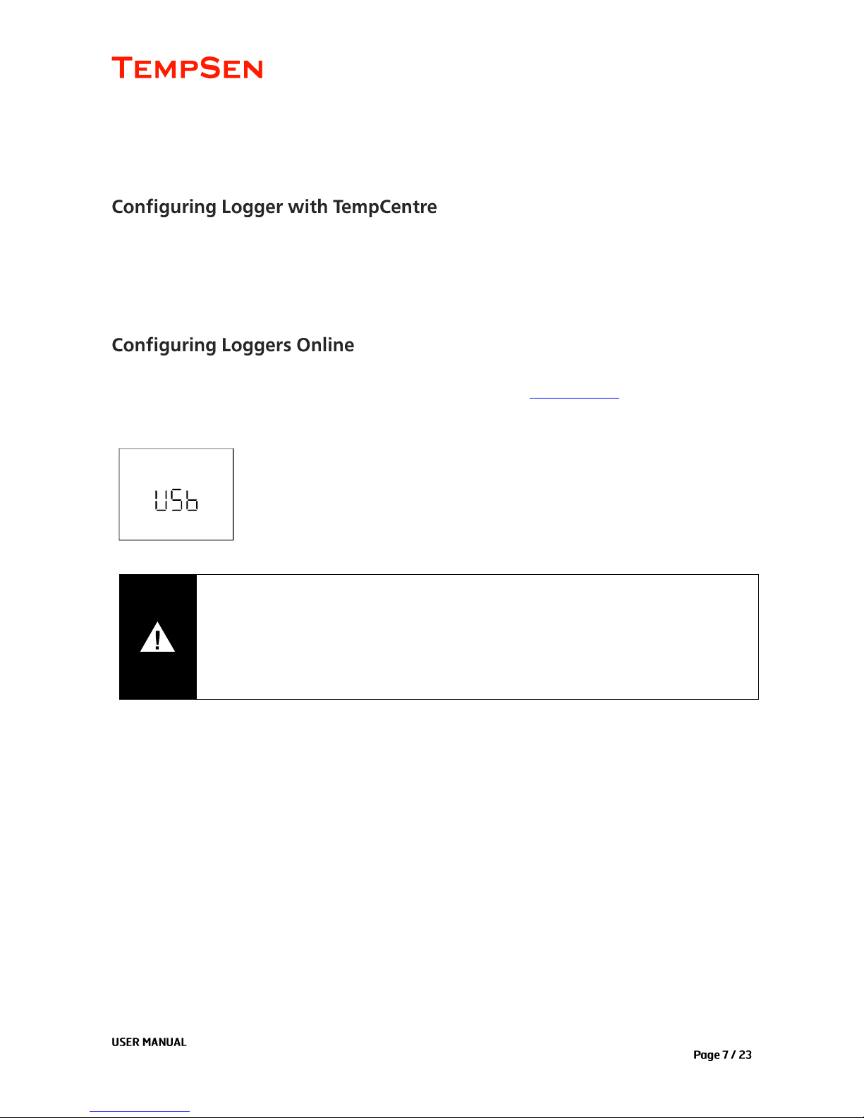
LCD displays “USB” when logger connected to PC.
IMPORTANT
Please only apply configuration profile the same product model on which configuration
file is created based.
Do not alter the configuration profile downloaded to avoid configuration error.
Configuration profile contains time zone information, so please do not use this file in
areas of different time zones, or it will result in incorrect time base.

UM-ITAG4-160217 REV.B
LCD displays “ConF” for configuration success when connection with PC
remains. (Only applicable to non-software configuration).
LCD displays “Err” for configuration failure, please re-configure device with
correct parameters.
Trip Number
A unique 10 digits alphanumeric number automatically created for identifying each monitoring task.
Trip Description
A brief note entered by user for describing monitoring task and showing on data report.
Logging Interval
The recording and sampling interval for data logger, optional from 1 minute to 2 hours.
Startup Mode
Manual Start
Device needs to be started by pressing Start/Stop button for 3 seconds
Start Delay
The time device needs to wait before recording starts after manually activated, optional from 1
minute to 10 days.
IMPORTANT
Configuration to data logger would erase all data recorded, so please make sure you have
save the data before configuration.
Do not remove data logger from PC before you are prompted of configuration success.

UM-ITAG4-160217 REV.B
Auto Start
Device automatically starts recording on the specific date/time preset, no need to press Start/Stop
button after configuration.
Button Settings
Disable Stop Button
This option is used to avoid mistaken Stop Button action, once enabled, device could not be
stopped by pressing Start/Stop button, recording stops when logging cycle completes, however,
you are still allowed to stop recording through TempCentre.
Alarm Settings
Alarm Mode
No alarm setting
High & Low alarm, 2 alarm ranges determined by 2 alarm limits.
Multiple Alarm ranges, 5 alarm ranges determined by 5 alarm limits.
High alarm zones: A1, A2, A3
Ideal range: A4 (No alarm will be triggered when data falls within this range )
Low alarm zone: A5, A6
▪
Only ITAG4 Bio supports multiple alarm ranges.
Alarm Type
Single Event
Alarm could only be triggered when data over high limit (or under low limit) not less than an alarm
delay continuously.
Cumulative Alarm
Alarm could be triggered once the cumulative total time data over high limit (or under low limit) is
not less than an alarm delay.

UM-ITAG4-160217 REV.B
PDF Report Settings
PDF Report Title
This report title would be used for PDF report created automatically by data logger.
Time Base
Select Time Zone and enable/disable Day Light Saving time (DST) for PDF report.
Language
Select language for PDF report.
LCD Screens after Configuration
Start Delay
LCD displays “Stby” after configuration.
Auto Start
LCD displays “Stby” and a Clock after configuration indicating logger is
waiting for Auto Start on pre-set time.

UM-ITAG4-160217 REV.B
RECORDING
Manual Start
Press and hold Start/Stop button for 3 seconds to manually active data logger, if logger was set to Start
Delay, then recording would only start after Start Delay time passes.
Start Delay
Start delay time and a Clock appear on LCD and logger begins
countdown after logger started manually, refresh frequency of countdown
time changes as per remaining delay time, for example, when there is 2
hours left, delay time refreshes each one hour, 59 minutes left, LCD
refreshes each 1 minute. (In this case, start delay time is 30 minutes)
Auto Start
Device starts recording on pre-set time automatically, no need to press Start/Stop button after
configuration.
▪
ITAG4 data logger could not be configured again after recording begins.

UM-ITAG4-160217 REV.B
“REC” appears in left bottom screen indicates logger is currently
recording.
LCD Examples - Home Screen
No Alarm Setting
Current Reading: 25.7°C
No Alarm, No Limit Violation Event
Current Reading: 12.3°C
*RH channel only available on ITAG TH
No Alarm
High alarm zone (Temp)
High alarm zone (RH)
Violation event: 2
Violation event:
0
Low alarm zone (Temp)
Low alarm zone (RH)
Violation event: 0
Violation event: 1
Alarm
High alarm zone (Temp): Alarm
High alarm zone (RH)
Violation event: 2
Violation event: 0
Low alarm zone (Temp)
Low alarm zone (RH)
Violation event: 0
Violation event: 3

UM-ITAG4-160217 REV.B
▪
For multiple alarm ranges model, Alarm zone A1, A2, A3 are deemed as high alarm zones, A5, A6
are deemed as low alarm zones, all numbers of violation events in each high alarm zone will be
added up and total number shows in high alarm zone area of home screen, the same applies to
low alarm zones.
Due to LCD only has 2 digits displaying number of violation events for each alarm zone, so 99 is
the biggest number on LCD indicating the violation events, please refer to data report for the real
number of violation events when LCD shows 99 for violation events.
LCD Examples – View Logging Statistics
Click on View/Mark button to view monitoring statistics and alarm information screen by screen.
Maximam Value
Minimum Value
Average Value
Statistics for each alarm zone
High Alarm Zone (Temp): Alarm
Violation Event: 3
Total violation time: 2 days 11 hours 35 minutes
High Alarm Zone (Temp) - A2: OK
Multiple Alarm Ranges
Violation Event: 3
Total violation time: 6 hours 30 minutes
Low Alarm Zone (RH): Alarm
Violation Event: 3
Total violation time: 45 minutes

UM-ITAG4-160217 REV.B
Press Start/Stop button and hold for at least 3 seconds to stop recording.
Logger would stop recording too after logging cycle completes (memory full).
Recording Stops
“StoP” displays after recording stopped.
▪
Logger could not be stopped by pressing Start/Stop button within 30 minutes after recording
started.

UM-ITAG4-160217 REV.B
DOWNLOADING DATA
Connect logger to USB port of PC, data logger will start generating PDF report and it may take couple of
seconds for the process to complete.
LCD displays “PdF” indicating logger is currently generating PDF report, then
changes to “USb” after PDF report is successfully created.
After PDF report is created, open removable storage device named “TempSenDisk” in computer, copy the
PDF report to your computer, then open and view it with Adobe PDF reader software.
▪
Logger would be ready for communication with TempCentre software only after PDF report is
completely created.
PDF Report
The PDF report automatically created by ITAG4 data loggers are protected and encrypted from tamper,
with all raw data embedded, you are allowed to open this PDF file with TempCentre for further analysis
and archiving, and upload it to TempSen’s Cold Chain CloudTM online data management, analysis and
sharing center, www.coldchaincloud.com, to enable shipment build and worldwide data sharing, alarm
notification between shipper, receiver and QA management personnel.
Authenticity and integrity of PDF reports downloaded from ITAG4 could be verified using TempCentre
(version 2.0 or higher) or Cold Chain CloudTM service.
IMPORTANT
Please DO NOT save the PDF report that you copied from logger as a new file. Please do
not perform any “Save” action through PDF reader software. Otherwise, content inside
PDF file will be reorganized by Adobe PDF reader and cause raw data embedded
unrecognizable.
Please DO NOT remove data logger from USB port while it’s still in the process of creating
PDF report (“PDF” on LCD indicates that logger is creating PDF report), Otherwise logger
would be seriously damaged.

UM-ITAG4-160217 REV.B
Connect logger to PC, open TempCentre software, and click Download in toolbar, then TempCentre would
search, connect logger and download data automatically.
Please remember to save data to data base of TempCentre by clicking “Apply” button in software
DATA RESULTS EXPLANATION
Current Status
Running status of logger when downloading data.
Start Time
The time the first data point is recorded at.
Stop Time
The time the last data point is recorded at.
Trip Length
Total recording duration time, which is calculated from the first point to
Total Violation Time (Total Time)
The total time measurement values violate each alarm limit.
Limit Violation Event (Events)
A consecutive series of data points over preset high alarm limit or under low limit would be deemed as one

UM-ITAG4-160217 REV.B
violation event. In example below, high alarm zone has three limit violation events.
Number of violation event for each alarm zone shows on LCD and in “Events” column of alarm statistics in
data report.
Alarm First Triggered Time (First Triggered@)
The time an alarm is first triggered at.
For example, logger is set to logging interval of 1 minute, alarm delay is 5 minutes, logger is started at
09:00, and readings are all over high limit after recording begins, so first alarm will be triggered at 09:05,
and this is the Alarm First Triggered Time.

UM-ITAG4-160217 REV.B
BATTERY
ITAG®4 series data loggers are equipped with one CR2032 lithium metal battery, which passed the Part III,
Sub Section 38.3 of the UN Manual of Tests and Criteria. ITAG®4 data logger is also certified to meet
requirements in General Requirements and Section II of Packaging Instruction 970, IATA Dangerous Goods
Regulations 56th Edition. ITAG®4 complies with DO160G Environmental Conditions and Test Procedures for
Airborne Equipment.
ITAG4 series data loggers are supplied power system disabled, shelf life (validity of device) is two years from
manufacturing date.
Expiry date is printed on the back of each logger, please make sure you will use the logger before expiry
date.
Once logger is connected to computer, power system of logger will be activated, then the guaranteed shelf
life will be reduced to one year, you need to use the logger ASAP. So please DO NOT connect logger to
computer if you do not plan to use the logger immediately.
A lightening icon appears at bottom of LCD means power is already active.
Please note two years shelf life is only applicable to ITAG4 loggers not connected to computer yet. Factory
programmed ITAG4 loggers come with one year shelf life.

UM-ITAG4-160217 REV.B
ERROR CODES
Error codes usually could be found on the upper left corner of a PDF report created by data logger, if you find
an error code in a data report, it means data logger detected an exception related to recording.
Code 0004 (*0004), logger used to be reset during recording, which may cause missing of data point.
Code 0005 (*0005), an internal time error is detected when activating a logger, to avoid creating incorrect
data record, logger would not be activated in this case until new configuration is carried out.
MKT
MKT (Mean Kinetic Temperature) is a simplified way of expressing the overall effect of temperature fluctuations during
storage or transit of perishable goods. Calculation,
ΔE = activation energy (standard value: 83.144 kJ/mol)
R = 8.314472 J/mol (universal gas constant)
T = temperature in degrees K
n = the number of sample periods over which data is collected
Note: ln is the natural log and ex is the natural log base.
The pharmaceutical and food industries are two closely regulated markets. The FDA provides regulations that require
warehouse and shipment temperatures to be closely controlled and monitored. In addition, the FDA requires welldocumented verification of these storage environments and any corrective actions taken if temperatures exceed
specified storage conditions.

UM-ITAG4-160217 REV.B
ADDITIONAL INFORMATION
LCD may function abnormally after taken out from environment down to -20°C to room temperature,
please wait for few minutes for it to restore to normal status.
To avoid damaging your data logger, please do not disconnect it from USB port while it is
communicating with the computer.
Do not use any aggressive cleaning agents or solvents to clean device.
Data stored in data logger is retrievable even battery runs out.
Please do not heat, microwave or recharge battery.
Please follow local regulations when recycling or disposing of data data logger.

UM-ITAG4-160217 REV.B
GLOSSARY
Terms
Explanation
Logging Interval
Unit time required to record one data point.
Start Delay
The time device needs to wait before starting recording after manually activated.
Alarm Delay
Time threshold required for triggering an alarm
Limit Violation
Measurement value goes above high limit or drops below low limit.
Violation Event
A consecutive series of data points over a high limit (or under a low limit) is
deemed as an alarm event.
Alarm Zone
Measurement ranges defined by alarm limits.
Trip Number
A unique 10 digits alphanumeric number automatically created for identifying each
monitoring task.
Trip Description
A brief note entered by user for describing a monitoring task and shows on data
report.
Temperature Start
After logger is manually activated, device starts recording when temperature
meets the preset temperature conditions.
Repeat Start
Repeat Start is an independent option of Startup, if enabled, you could restart
Alpha data logger for next round of monitoring with the same recording parameters
of previous recording by pressing Start/Stop button, no need to program the logger
again.
Auto Start
Device automatically starts recording on the specific date/time preset, no need to
press Start/Stop button after configuration.

UM-ITAG4-160217 REV.B
WARRANTY
TempSen warrants this TempSen-branded hardware product against defects in materials and workmanship under normal use for a
period of ONE (1) YEAR from the date of retail purchase by the original end-user purchaser (“Warranty Period”). If a hardware defect
arises and a valid claim within the Warranty Period, as its option and to the extent permitted by law, TempSen will either (1) repair the
hardware defect at no charge, using new parts or parts equivalent to new in performance and reliability, (2) exchange the new product
with a product is new or equivalent to new in performance and reliability and is at least functionally equivalent to the original product, or
(3) refund the purchase price of this product. TempSen may request that you replace defective parts with new or refurbished userinstallable parts that TempSen provides in fulfillment of its warranty obligation. A replacement product or parts, including a userinstallable part that has been installed in accordance with instructions provided by TempSen, assumes the remaining warranty of the
original product or ninety (90) days from the date of replacement or repair, whichever provides longer coverage for you. When a product
or part is exchanged, any replacement item becomes your property and the replaced item becomes TempSen’s property. Parts provided
by TempSen in fulfillment it’s warranty obligation must be used in products for which warranty service is claimed. When a refund is
given, the product for which the refund is provided must be returned to TempSen and becomes TempSen’s property.
EXCLUSIONS AND LIMITATIONS
This Limited Warranty applies only to the hardware product manufactured by or for TempSen that can be identified by the “TempSen”
trademark, trade name, or logo affixed to it. The Limited Warranty does not apply to any non-TempSen hardware product or any
software, even if packaged or sold with the TempSen hardware. Manufacturers, suppliers, publishers, other than TempSen, may provide
their own warranties to the end user purchaser, but TempSen, in so far as permitted by law, provides their products “as is”. Software
distributed by TempSen with or without the TempSen brand name (including, but not limited to system software) is not covered under
this Limited Warranty. Refer to the licensing agreement accompanying the software for details of your rights with respect to its use.
TempSen does not warrant that the operation of product will be uninterrupted or error-free. TempSen is not responsible for the damage
arising from failure to follow instructions relating to the product’s use.
This warranty does not apply: (a) to consumable parts, such as batteries, unless damage has occurred due to a defect in materials or
workmanship; (b) to cosmetic damage, including but not limited to scratches, dents, and broken plastic on ports; (c) to damage caused
with non-TempSen products; (d) to damage caused by accident, abuse, misuse, flood, fire, earthquake, or other external causes; (e) to
damage caused by operating the product outside the permitted or intended uses described by TempSen; (f) to damage caused by
service (including upgrades and expansions) performed by anyone who is not a representative of TempSen or TempSen Authorized
Service Provider; (g) to a product or part that has been modified to alter functionality or capability without the written permission of
TempSen; or (h) if any TempSen serial number has been removed or defaced.
IMPORTANT: DO NOT OPEN THE HARDWARE PRODUCT. OPENING THE HARDWARE PRODUCT MAY CAUSE DAMAGE THAT IS
NOT COVERED BY THIS WARRANTY. ONLY TEMPSEN OR AN AUTHORIZED SERVICE PROVIDER SHOULD PERFORM SERVICE
ON THIS HARDWARE PRODUCT.

UM-ITAG4-160217 REV.B
REVISION HISTORY
Revision
Date
Details
A
02/17/2016
First version
B
03/02/2016
Added recording results explanation
 Loading...