

Temprite Industries CMA Installation, Operation And Maintenance Manual

IOMCMA-5
INSTALLATION, OPERATION AND
MAINTENANCE MANUAL FOR CMA MODEL
DIRECT GAS-FIRED HEATERS WITH DDC CONTROLS
ATTENTION: READ THIS MANUAL AND ALL LABELS ATTACHED TO THE UNIT CAREFULLY BEFORE
ATTEMPTING TO INSTALL, OPERATE OR SERVICE THESE UNITS! CHECK UNIT DATA PLATE FOR
TYPE OF GAS AND ELECTRICAL SPECIFICATIONS AND MAKE CERTAIN THAT THESE AGREE WITH
THOSE AT POINT OF INSTALLATION. RECORD THE UNIT MODEL AND SERIAL No.(s) IN THE SPACE
PROVIDED. RETAIN FOR FUTURE REFERENCE.
FOR YOUR SAFETY
The use and storage of gasoline or other flammable vapors and liquids in open
containers in the vicinity of this appliance is hazardous.
POUR VOTRE SÉCURITÉ
L'utilisation et l'entreposage d'essence ou d'autres liquides ou produits émettant des vapeurs
infl ammables dans des récipients ouverts à proximité de cet appareil est dangereux.
FOR YOUR SAFETY
If you smell gas:
1. Open Windows
2. Don’t touch electrical switches.
3. Extinguish any open fl ame.
c
4. Immediately call your gas supplier.
Si vous sentez une odeur de gaz :
1. Ouvrez les fenêtres.
2. Ne pas actionner d'interrupteur.
3. Éteindre toute fl amme ouverte.
4. Appelez immédiatement votre
fournisseur de gaz.
POUR VOTRE SÉCURITÉ
WARNING: Improper installation, adjustment, alteration, service or maintenance can
cause property damage, injury or death. Read the installation, operating and maintenance
instructions thoroughly before installing or servicing this equipment.
AVERTISSEMENT : Une installation défi ciente, de même qu'un mauvais réglage,
modifi cation, entretien ou maintenance peuvent occasionner des dommages matériels, corporels voire causer la mort. Lire attentivement les instructions d'installation,
d'utilisation et d'entretien avant d'installer ou d'intervenir sur cet appareil.
WARNING
Install, operate and maintain unit in accordance with manufacturer's instructions to avoid
exposure to fuel substances or substances from incomplete combustion which can cause
death or serious illness. The state of California has determined that these substances
may cause cancer, birth defects, or other reproductive harm.
Installer Please Note: This equipment has been test fi red and inspected. It has been shipped
free from defects from our factory. However, during shipment and installation, problems such as
loose wires, leaks or loose fasteners may occur. It is the installer's responsibility to inspect
and correct any problems that may be found.
4830 Transport Drive, Dallas, TX 75247 Phone: 214-638-6010 Fax: 214-905-0806
7555 Transmere Drive, Mississauga, ON L5S 1L4 Phone: 905-672-6123 Fax: 905-672-6124
www.tempriteheating.com
INSTALLER'S RESPONSIBILITY

SECTION I - FOREWARD
As is the case with any fi ne piece of equipment, care
must be taken to provide the proper attention to the
operation and maintenance details of this machine.
This manual of instructions along with the Digital
Control System user manual has been prepared in
order for you to become well-acquainted with those
details, and in doing so, you will be able to give your
Direct Gas-Fired System the care and attention which
any piece of equipment needs and deserves.
It is the customer and installation personnel
responsibility to determine if the unit is equipped
with all of the safety devices required for the
particular application. Safety considerations
include the accessibility of the unit to non-service
personnel, the provision of electrical lockout
switches, maintenance procedures, and automatic
control sequences. Clearly mark all emergency
shutoff devices.
*IMPORTANCE NOTICE*
Temprite assumes no responsibility for loss or damage
in transit; therefore, you should protect yourself by
following these instructions:
Bill Of Lading
Save your bill of lading. It is a contract, and you will
need it, provided you have to fi le a loss or damage
claim. Remember, claims are outlawed after nine
months.
Loss In Transit
Before you sign for this shipment, check against the bill
of lading, also the transportation company’s delivery
ticket. Make sure that you get the exact total of articles
listed. Should the delivery ticket show more or less
items than are offered, then the carrier’s agent must
mark the difference on your freight bill before you sign.
Visible Damage In Transit
If anything is damaged, accept the shipment only if
the carrier’s agent places a notation on your freight
bill explaining the nature and extent of damage. Upon
inspection of article, make claim to the delivering
carrier.
Table of Contents
Section I: Foreword, Table of Contents,
and Important Notice .................................. 2
Section II: General Information .................................... 3
Section III: Installation .................................................4
Section IV: Pre-Start Up .............................................. 8
Section V: Unit Start Up ...............................................9
Section VI: Unit Shut Down ....................................... 11
Section VII: Troubleshooting Guide ........................... 12
Section VIII: Maintenance Schedule
and Lubrication Requirements............... 24
Section IX: Mestek Burner ......................................... 29
Section X: Manifold and Valve Adjustments ..............30
Section XI: Thermistor Curves ...................................31
Section XII: Replacement Parts................................. 32
Section XIII: Recirculating Units ................................ 32
Concealed Damage In Transit
Sometimes transit damage is not noticed until the
goods are unpacked. In such cases, notifi cation to
the carrier must be made within fi fteen (15) days of
receipt of shipment. In such cases, save the packages
and packing material, then notify the transportation
company at once, and request an inspection. When
the inspector calls, have him make out and leave a
“concealed” bad order report. He is obliged to give one
to you. Insist on it.
Disposition Of Damaged Atticles
Never return damaged articles to us. They are the
property of the transportation company when the claim
is fi led. They will give you disposition instructions.
Packing
We comply with the packing requirements of the
transportation companies, and your bill of lading
proved that everything was in good condition when
shipped. That bill of lading contract requires them to
deliver in perfect condition.
– 2 –

SECTION II - GENERAL INFORMATION
A. Purpose
The purpose of this manual is to present a guide for
proper installation, maintenance, and operation of the
Direct Gas-Fired System, and supplement, but not to
replace, the services of qualifi ed fi eld service person-
nel to supervise the initial start-up and adjustment
of the unit. Persons without previous experience with
large commercial and industrial heating equipment
should not attempt the initial adjustment and checkout
procedure which is essential before such installations
may be considered ready for operation. This manual
should be made readily available to all operating personnel as an aid in troubleshooting and proper maintenance.
B. Shipping
Base Direct Gas-Fired units are shipped completely
assembled where shipping limitations allow. Optional
inlet hoods, fi lter and/or damper sections, or other
large accessories are assembled and shipped mounted and wired whenever possible within limitations
of shipping and handling. Any optional accessories
shipped separately are shipped as assembled sections. Any wired accessories which have been disassembled for separate shipment require no additional
conduit or wire for fi eld reassembly. All wire leads will
be tagged for ease of reconnection in the fi eld.
If the unit and/or accessories cannot be installed
immediately, they should be stored in a clean dry
environment. If this is not possible and the unit
must be stored outdoors, it should be protected
from the weather with tarpaulins or plastic
coverings. Do not assume that simply covering a
unit will keep insects, dust and condensation out
of the unit and critical components. Rotate the
fan(s) monthly.
Shipments are made F.O.B. Dallas, Texas by fl at-
bed truck. The unit is securely strapped, tied, and
blocked to prevent shipping damage. All shipments
are checked by an inspector before they are accepted
by the carrier. Parts that are shipped unmounted are
noted on the bill of lading. These parts, where feasible,
are packaged and shipped with the units. Upon receipt
of shipment, all units should be checked against the
bill of lading to insure all items have been received. All
equipment (and any optional accessories) should be
checked carefully for physical damage in the presence
of the carrier’s representative. If parts are missing or
damage has occurred, a claim should be fi led immedi-
ately with the carrier.
All Direct Gas-Fired units are given a complete operations test and control circuit checkout before shipment.
Copies of the wiring diagram, piping diagram and
bill of material are included with each unit shipped. If
correspondence with the factory is necessary, please
provide the unit model and serial number.
C. Optional Factory Service
Periodic service on any piece of mechanical equipment is necessary for effi cient operation. A nationwide
service support network is available to provide quick
and dependable servicing of make-up air, heating,
ventilating, or air handling types of equipment. Factory
start-up service is also available which includes the
presence of a service engineer to supervise the initial
start-up and adjustment of the equipment and provide
instructions for the owner’s maintenance personnel in
proper operations and maintenance. Consult factory
for quotations on start-up or periodic service.
Prior to beginning installation of a unit that has been in
storage for weeks or months, the unit and its components should be closely inspected.
– 3 –
SECTION III - INSTALLATION
FOR CANADIAN INSTALLATIONS ONLY
1. All installations must conform with local building
codes, or, in the absence of local codes, with
current CAN/CGA-B149-Installation Codes For
Gas Burning Appliances and Equipment.
2. All electrical connections must be in accordance with Canadian Electrical Code, Part 1,
CSA Standard C22.1.
This equipment must be installed and wired in accordance with regulations of the National Board of
Fire Underwriters, National Electrical Code, and local
governing bodies. The following recommendations are
not intended to supplant any requirements of federal,
state, or local codes having jurisdiction. Authorities
having jurisdiction should be consulted before installations are made. Local codes may require additional
safety controls and/or interlocks.
All installations in airplane hangers must be in accordance with current ANSI/NFPA No. 409. All installations in public garages must be in accordance with
current NFPA No. 88A and NFPA No. 88B.
CAUTION: Do not install heating system in corrosive
or fl ammable atmospheres! Premature failure of, or
severe damage to the unit will result!
During transit, unloading and setting of the unit, bolts
and nuts may have become loosened, particularly
in the pillow block ball bearing assemblies in the fan
section. It is recommended that all nuts and set screws
be tightened. Turn fan shaft by hand to make certain
that blower does not rub against blower housing, and
that bearing set screws are tight. If units are not set
immediately, cover all openings that might be exposed
to the weather.
Open the cover on the electrical control box located on
the unit. Inspect all wire terminals and wiring terminations to ensure that all connections are tight.
If units are not set immediately, cover all openings that
might be exposed to the weather.
Rotate fans monthly.
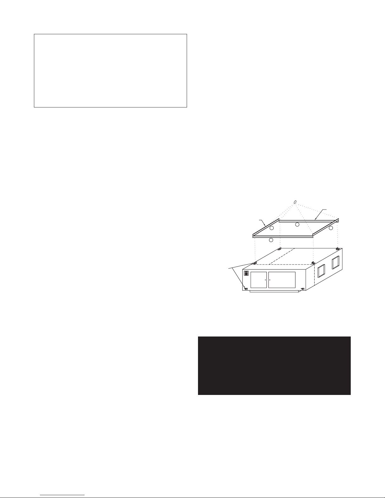
RIGGING AND MOUNTING DATA - DIRECT FIRED UNITS
SPREADER
BAR
SPREADER
BAR
A
B
B
A
CAUTION: Heating system must not be installed in
locations where air for combustion would contain
chlorinated, halogenated or acidic vapors. If located
in such an environment, premature failure of the
unit will occur!
A. Handling the Equipment
The Direct Gas-Fired unit has been designed for
rigging and handling through the use of special lifting
lugs installed on the sides of each unit. As explained
previously, the basic unit is designed for shipping in
one piece where shipping limitations allow. Some
optional accessories may require fi eld mounting.
The Direct Gas-Fired unit has been designed for
rigging and handling through the use of special lifting
lugs installed at each corner of unit. When unloading
and setting the unit, use the lifting lugs provided or
move the equipment on rollers. Hooks, jacks, or chains
must not be used around the casing, main control
panel or exterior mounted controls.
LIFTING LUGS
PROVIDED IN ONE
OF TWO LOCATIONS
A - USE WHEN LIFTING OVER 3,000 LBS.
B - USE WHEN LIFTING UNDER 3,000 LBS.
08/16/07 C000539A
WARNING: To insure that a proper unit lift is
made, lift unit approximately 24 inches and
verify proper center of gravity lift point. To avoid
dropping of unit, reposition lifting point if unit
is not level. Failure to properly lift unit could
result in death or serious injury or possible
equipment or property-only damage.
– 4 –
B. Locating the Unit
Prior to locating the unit, authorities having jurisdiction should be consulted before installations are made.
Approval permits should be checked against the unit
received.
On Direct Gas-Fired units, which recirculate room air,
outside ventilation air must be provided in accordance
with the information shown on the heater nameplate.
All ventilation air to the heater must be ducted directly
from the outside. See Section XIII.
If in doubt regarding the application of this appliance,
consult the factory.
Use extreme caution in handling the curb. Proper
handling and positioning will assure a water-tight curb
unit installation.
Re-check approval prints prior to installation. Be sure
that there are no obstructions to ducting and that
proper planning has been exercised in connection of
piping and/or electrical services.
The curb assembly may be bolted or welded to either
trusses or roof decking; however, connection to roof
trusses is recommended. The curb is designed to carry
the weight of the unit. Additional support is required for
certain applications.
Locate the unit exactly level. Special attention should
be given to the duct, electrical, and fuel connection
points. Install duct work with adequate fl exible connec-
tions to isolate vibration from the duct work. All duct
work should have taped or caulked seams. Duct work
should be properly sized so as not to inhibit airfl ow.
This information should be cross-checked with the
position of support beams and stand pipes to insure
that clearance dimensions coincide with those of the
unit. The minimum clearance to combustible material
must be maintained as listed in Table 1.
Table 1
Minimum clearance to combustible material,
also consult local codes and regulations.
Clearances to Combustible Material
Vertical Units Horizontal Units
Front* 39 inches 36 inches
Rear 6 inches 6 inches
Right 6 inches 6 inches
Left 6 inches 6 inches
Top 12 inches 12 inches
Floor Zero 6 inches
*Consider control side as front of unit.
**Optimum clearance for shaft removal would be
equivalent to cabinet width.
Make a visual inspection to insure no damage has occured to the unit during installation.
Placement of the curb is critical in squareness and
leveling. Shims for leveling must be applied to the
curb; application of shims to the unit will tend to
destroy the sealing effect after installation. Make sure
sealing tape is in place before unit is set. Be careful
not to allow gaps where two pieces of sealing tape
meet. A bubble level must be used in the leveling
process. Measure across diagonals to check for
squareness. Allowable tolerance is 1/4" difference
between diagonal measurements. Double-check
approval prints before setting the unit.
Upon completion of setting the curb, apply roofi ng
material and fl ashing as required. On outdoor curb
mounted installations, fl ash and seal the roof curb to
prevent leakage. The cross section of factory provided
curb is formed to accept wood nailing strip and insulation provided by others.
D. Location of Accessories
Where applicable, standard or optional accessories will
be placed inside the fan section of the unit for shipment,
and must be removed and installed by the mechanical
or electrical contractor.
Remotely located discharge or inlet dampers must be
equipped with an end switch and interlocked to insure
maximum design opening before starting and running
circuits may be energized.
C. Curb Mounted Units
Outdoor units can be supplied with an optional roof
curb. The curb greatly facilitates installation thereby
reducing installation costs. All connections to the unit:
duct, piping, electrical power and control wiring can
be made through the roof opening. The curb may be
shipped prior to unit shipment. All curbs are shipped
un-assembled from the factory.
Field constructed intake accessories should be properly
designed to minimize the entry of rain and snow.
Adequate building relief must be provided, so as to not
over-pressurize the building, when the heater is
operating at its rated capacity. This can be accomplished by taking into account, through standard
engineering methods, the structure’s designed infi ltra-
tion rate, by providing properly sized relief openings,
by interlocking a powered exhaust system, or by a
combination of these methods.
– 5 –

E. Electrical Connections
F. Field Piping
WARNING: Open all disconnect switches and
secure in that position before wiring unit.
Failure to do so may result in personal injury or
death from electrical shock.
WARNING: Controls must be protected from
water. Do not allow water to drip on the ignition
system.
NOTE: Before installing any wiring, check the unit
rating plate for supply power voltage and minimum
ampacity.
All electrical connections must conform to the current
edition of: ANSI/NFPA No. 70 National Electrical Code
and applicable state and local codes; in Canada, to the
Canadian Electrical Code, Part 1 CSA Standard C22.1
and applicable provincial and local codes.
Since shipment of unit may require disassembly after
factory check and test, reconnection of some electrical
devices will be required in the fi eld. Connect electrical
wires (supplied in factory furnished conduit) to appropriate terminals. All leads are tagged to facilitate fi eld
connections. See wiring diagram provided with equipment. Complete all wiring to any optional accessories
as shown on unit bill of material and electrical wiring
diagram as required before applying voltage to the unit.
Gas Piping
All gas piping must be in accordance with the requirements outlined in the National Fuel Gas Code - ANSI
Z223.1. It is required that a ground union be installed
adjacent to the manifold for easy servicing. A drip leg
and/or fi lter should be provided upstream of the unit’s
inlet gas connection. An additional shut-off must be
located external of the unit’s enclosure. The location of
this valve must comply with all local codes. A 1/8 inch
N.P.T. plugged tapping, accessible for test gauge connection, must be installed immediately upstream of the
gas supply connection to the unit.
WARNING: To avoid equipment damage or
possible personal injury, disconnect gas piping
to this unit until a supply line pressure/leak test
has been completed. Connecting the unit before
completing the pressure/leak test may damage
the unit gas valve and result in a fi re hazard.
DANGER: Never use an open fl ame to detect
gas leaks. Explosive conditions may exist which
would result in personal injury or death.
On vertical units there is a factory installed “Burner
Cleanout” pipe located on the opposite end of the gas
piping compartment. This is a clean out to drain any
condensate that may have collected in the line burner.
Entry location for all fi eld-installed and control wiring is
through the control panel.
If optional disconnect is not furnished with heater, the
fi eld provided disconnect must be of the proper size
and voltage. Refer to unit rating plate for minimum
circuit ampacity and voltage. The disconnect must be
installed in accordance with Article 430 of the current
edition of ANSI/NFPA No. 70 National Electrical Code.
Check the supply voltage before energizing the unit.
The maximum voltage variation should not exceed
± 10%. Phase voltage unbalance must not exceed 2%.
NOTE: Should any original wire supplied with the
heater have to be replaced, it must be replaced
with wiring material having a temperature rating of
at least 105° C.
REMARQUE : Dans le cas où un quelconque des
câbles livrés avec l'unité devait être remplacé, il
doit être remplacé avec des câbles prévus pour
résister à une chaleur d'au moins 105° C.
WARNING: DO NOT connect supply gas to this
pipe.
The gas line should be supported so that no strain
is placed on the unit. Pipe compounds which are not
soluble to liquid petroleum gases should be used on
threaded joints.
Refer to the heater’s rating plate for determining the
minimum gas supply pressure for obtaining the maximum gas capacity for which this heater is specifi ed.
Une tuyauterie adéquatement dimensionnée doit être
posée jusqu'à l'unité. Veuillez noter que la pression de
la tuyauterie d'alimentation en gaz doit correspondre
à celle spécifi ée sur la plaque d'identifi cation, lorsque
l'unité fonctionne à plein rendement.
Refer to the heater’s rating plate for determining the
maximum supply pressure to the heater.
The appliance and its individual shutoff valve must
be disconnected from the gas supply piping system
during any pressure testing of that system at test
pressures in excess of 1/2 PSIG.
– 6 –

The appliance must be isolated from the gas supply
piping system by closing it’s individual manual
shutoff valve during any pressure testing of the gas
supply piping system at test pressure equal to or
less than 1/2 PSIG.
Correctly sized piping must be run to the unit.
Please note that gas line pressure must be
as shown on specifi cation plate when unit is
operating at full input. The high-pressure regulator
and relief valve should be, if possible, mounted
at least 5 to 10 feet upstream from the appliance
regulator on the unit (if possible).
Building Pressure Transducer Piping (PT-13)
Pipe the high side to location inside the building that
will not be affected by air movement. Pipe the low side
to the atmosphere, positioned so it will not be affected
by the wind and not exposed to the elements. Be sure
that all tubing is clean and clear of any debris before
installing tubes on the transducer.
disconnect switch.
2. Field wiring is typically indicated on the wiring
diagram as dashed lines. When running any fi eld
wiring for control circuit be sure wire is sized for
a maximum 10% voltage drop. Check the VA
rating of control circuit transformer to determine
maximum load.
3.
Mount and wire remote control panel, thermostats,
temperature sensors, and any other fi eld installed
controls as indicated on the unit control wiring diagram.
4.
Connect all wires to the appropriate fi eld wiring
terminals and any shielded or twisted wires as indicated
on the unit control diagram.
5. Field wiring shall have a temperature rating of at
least 105°C. The minimum size of the supply cable
circuit shall be suffi cient for the maximum ampacity
of the heater.
L'installation éléctrique d'utilisateur aura une
température qui évalue d'au moins 105°C. La
minimum de source du circuit de câblage sera
suffi sante pour le ampacity maximum de l'appareil
de chauffage.
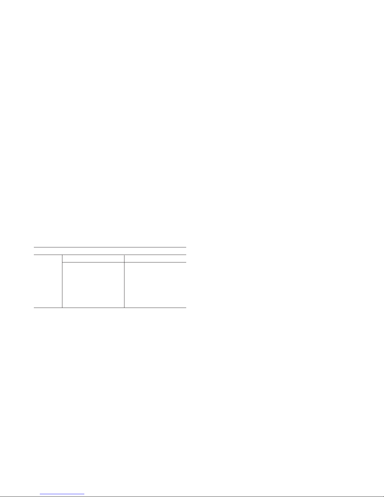
Flow Station Transducer Piping (PT-15)
Pipe the high side to the upstream connection and
low side to the downstream connection of the Airfl ow
Station as shown in Drawing # C000643 below. Be
sure that all tubing is clean and clear of any debris
before installing tubes on the transducer.
G. Field Wiring and Remote Control Installation
1. Connect the power lines to the line side of
the power distribution block or optional main
AIRFLOW STATION LAYOUT
HEATER
CASING
RA DAMPER
TUBE CONNECTION
STATIC PRESSURE
NOTE: RUN TUBE CONNECTIONS
TO TRANSDUCER (PT-15) IN
UNIT CONTROL ENCLOSURE
LOW PRESSURE
SENSING TUBE
H. Locating Temperature Controls
The room or outdoor sensors should be mounted
where they will not be subjected to direct impact of
the heated air or radiant heat from the sun. It is also
recommended that thermostats, especially those with
mercury bulb contacts, be mounted on a vibration free
surface. The side of building columns away from the
heater or interior walls are usually the location best
suited for mounting thermostats.
Controls with outdoor sensors require that the outdoor
sensor be shielded from direct radiation from the sun. Unit
mounted sensors are factory located and mounted.
HIGH PRESSURE
TUBE CONNECTION
TOTAL PRESSURE
SENSING TUBE
AIRFLOW STATIO N
EXTERIOR INSULATION
FIELD PROVIDED WHEN
MOUNTED OUTDOORS
– 7 –
BULLET
AMPLIFIER WING
(SHEET METAL STRIP)
C000643

SECTION IV - PRE START-UP
Do not attempt start-up without completely reading
and understanding this manual, along with the
Digital Control Sysem user manual.
A. Pre Start-Up
The owners representative or equipment operator
should be present during start-up to receive instructions on care and adjustments of the equipment.
All equipment has been factory tested, adjusted,
metered and inspected to meet conditions set at
the time the order was placed. Only minimal
adjustments should be required. All information
in this service manual is typical. All products are
semi-custom and changes may occur.
Suggested Tools and Instruments
Volt/Ohm Meter Thermometer
Tachometer Ammeter
Manometer (0-10" W.C.) Microammeter
Standard Hand Tools D.C. Volt Meter
Gas Pressure Gauge (0-35 lbs.) BACview 6
CAUTION: Line side of disconnect may be energized.
Follow proper “lockout/tagout” procedures.
NOTE: All servicing and adjustments of the Direct
Gas-Fired unit should be performed by a qualifi ed
service engineer.
Perform a visual inspection, internally and externally,
to make sure no damage has occured and that
everything is secure. This inspection is very important
and should be completed with greatest care given to
detail. A good pre-start inspection will insure against
possible unit damage on start-up and will save
valuable analysis time.
1. Check that the physical condition of the unit
exterior is acceptable.
2. Check that the insulation inside of unit is properly
secured.
3. Remove all shipping blocks, brackets and bolts
from supply fan base with optional isolation base.
4. Check all wiring for loose connections and tighten
if necessary.
5. Inspect all fan and motor bearings and lubricate if
necessary.
CAUTION: DO NOT RUPTURE GREASE SEALS.
6. Inspect pulleys and belts for tightness, tension and
alignment. Do not overtighten belts.
7. Check set screws on all bearings, pulleys, fans and
couplings for tightness.
8. Check voltage supplied to disconnect switch; the
maximum voltage variation should not exceed
± 10%. Phase voltage unbalance must not exceed 2%.
9. Check thermostat(s) for normal operation.
10. Check that system duct work is installed and free
from obstructions.
11. Check that fans turn free in housing.
12. Check that the area around the unit is clear of
fl ammable vapors or containers of fl ammable
liquids.
13. Check that all piping connections, particularly
unions, are tight. Check all gas piping for leaks
using a soap bubble solution. The most common
types of problems found relative to the gas train
itself is foreign material within the gas piping. This
will interfere with the proper operation of the gas
train components and burner. Purge all air from
gas lines per gas codes.
14. Check that all accessories requiring fi eld wiring
have been properly installed.
15. Check burner for proper location and alignment.
16. Check that fi lters, fi lter stops, accessories and ship
loose items are installed correctly.
17. Check that vent lines (if applicable) are run to
atmosphere on gas regulators and pressure
switches for indoor units. Vent lines should
terminate outside the building, with a turndown
elbow and bug screen. Note that some units will
use vent limiters and vent lines are not required.
If vent lines are even partially plugged, this will
interfere with proper venting of pressure control
devices.
Check that all manual gas shut-off valves are closed.
18.
19. When failure or malfunction of this heater creates a
hazard to other fuel burning equipment, (e.g. when
the heater provides make-up air to a boiler room),
the heater is to be interlocked to open inlet air
dampers or other such devices.
20. Motor overload relay setting should match the
motor’s nameplate full load amperage.
21. Check that dampers and linkages are free to move,
and that linkages are tight.
22. The unit may require that a Return Airfl ow Station
be fi eld installed. Be sure all tubing connections
are in the correct location as shown in drawing
#C000643.
23. Check to ensure all manual reset safety devices
have been reset and limits are in the normal
operating position.
24. If inlet duct is attached to the heater, a purge
timer must be provided and set to purge 4
times the inlet duct volume.
Purge time in seconds = 4 x L x W x H x 60
SCFM
L = duct length in feet, W = duct width in feet,
H = duct height in feet, SCFM = rating plate air
throughput.
Refer to the electrical schematic for the proper
circuit placement. Purge timer P/N 65.0711.00.
– 8 –

SECTION V - UNIT START-UP GENERAL
Before attempting to start the heater read and
understand the the sequence of operations
electrical schematic, ignition module, control
components, gas train, burner and the Digital
Control System user manual.
WARNING: During installation, testing, servicing
and trouble shooting of this product, it may
be necessary to work with live electrical
components. Have a qualified licensed
electrician or other individual who has been
properly trained in handling live electrical
components to perform these tasks. Failure to
follow all electrical safety precautions when
exposed to live electrical components could
result in death or serious injury.
Make sure all manual gas valves are closed.
Make sure all doors and service panels have been
closed or replaced.
Turn main disconnect switch off. Check the incoming
line voltage to match unit rating plate rating. If voltage
is over ±10% of nameplate rating or phase voltage
unbalance is over 2%, notify contractor or power
company.
Fans Are Enabled And Disabled By The Following:
MDT And MRT Standard:
By rotating the remote “Temperature Setpoint” knob
(MP-15).
Clockwise will enable the fans.
Counterclockwise will disable the fans.
MRT-PRO With Smart Room Sensor:
To enable the fans and place the unit in the Occupied
Mode press the “Manual On” button on the face of
the (TS-02) MRT-PRO room sensor. Pressing the
“Warmer” button will add 30-minute increments of
time for a total of 9-hours of operating time. To disable
the fans and place unit in the Unoccupied Mode press
and hold down the “Manual On” button. Alternately
pressing the “Manual On” button will also decrease
the amount of operating time until it reaches zero and
turns the fan off.
MRT Expert or VDT Expert With A BACview (KP-01):
To enable the fans go to “Unit Modes” and enter
[MANUAL], this mode will enable the fans.
To also enable the fans go to “Unit Modes” and enter
[AUTO], this mode has four different functions that
control the fans and unit operation. They are a Time
Clock, Heating and Cooling Night Setbacks, and signal
from an external source to an auxiliary digital input.
To disable the fans go to “Unit Modes” and enter
[OFF].
NOTE: A BACview or PC is required to change Unit
Modes. For a more detailed control sequence see
the (Digital Control System User Manual).
Turn main disconnect switch on and Enable fans.
Damper opens (if applicable). After end switch has
proven damper is open, the blower fan turns on.
(see operating modes in Digital Control System user
manual)
Disable the fans. Check supply blower for proper
rotation.
NOTE: To change rotation of the blower, simply
interchange any two (2) of the line leads of the
motor starter for three (3) phase motors. On single
phase motors refer to motor nameplate.
Enable the fans. Check for proper blower rpm. Check
that all motor amp draws do not exceed rating plate
ratings and overloads are set to motor rating plate
amps.
Check all dampers for proper operation, and linkage
does not bind, see “Sequence of Operation”, and
Digital Control System user manual for damper control
modes.
Disable the fans.
NOTE: Before attempting to light the main burner
you need to review Section X for proper Manifold
and Valve Adjustments. A BACview 6 or PC will be
required to change setpoints.
Check the gas supply pressure by replacing the plug
fi tting on the gas line with a pressure gauge having
appropriate range, and opening the manual gas
valve. Check that the pressure reading is within the
specifi ed range on the rating plate.
NOTE: To adjust gas pressure on supply lines
where a regulator has been installed (to reduce the
inlet pressure to rating plate maximum pressure),
remove dust cap of main gas regulator and turn
adjusting screw clockwise to increase pressure or
counter-clockwise to decrease pressure.
Connect a DC Microammeter between SENSE
terminal and fl ame rod sensing wire.
– 9 –

Open fi rst main gas shut-off valve slowly. Reset high-
low gas pressure switches (if applicable). Check main
gas line for leaks using soap solution.
Heat is Enabled By The Following:
MDT And MRT Standard:
To enable the heat, rotate the “Temperature
Setpoint” knob (MP-15) clockwise to the desired
setpoint above the actual air temperature. The
o
allowable temperature range is 55
to 90oF.
MRT-PRO With Smart Room Sensor:
To enable the heat, press the “Warmer” or “Cooler”
button on the face of the remote MRT-Pro room sensor
(TS-02) to the desired room setpoint. Each push of the
button changes the temperature setpoint by 1o F. The
setpoint can be changed a maximum of + 10oF from
the default of 65oF. Changing the heating setpoint
also changes the cooling setpoint.
MRT Expert or VDT Expert With A BACview (KP-01):
To enable the heat for MRT Expert scroll through
the “Setpoints” menu in the BACview and enter the
desired room Heating Occupied and Unoccupied
Setpoints. For VDT Expert enter the desired Heating
Discharge Air Setpoint.
Energy Savings Modes:
There are 3 Energy Savings Modes that could
disable the burner.
NOTE: A BACview or PC is required to change
Setpoints. For a more detailed control sequence,
see the Digital Control System Users Manual.
Setting Main Flame
CAUTION: You will have approximately three (3)
minutes before the unit shuts down on Freezestat
(Low Discharge Temperature, if you have
disconnected plug wires TS-01 and TS-03). Referred
to in Section X.
NOTE: 3 OR 4 TRIALS MAY BE NEEDED TO
PURGE AIR FROM GAS LINE.
Install manometer at test port on the last tee of the
burner manifold, or MR valve test port.
Slowly open last manual gas shut-off valve.
Enable the fan and burner. Unit will run for 5 seconds
before valve opens and burner lights if all safeties and
limits are in normal operating mode.
NOTE: This is a direct spark ignition burner. Low
fi re may need to be adjusted fi rst in order to light
the burner.
Adjust high fi re pressure reading (from manometer) to
match Normal Manifold Pressure fi ring rate shown on
unit rating plate.
Refer to Valve Adjustment instructions in Section X
for setting high and low fi re gas pressure settings.
The high fi re setting must be made before adjusting
low fi re. Adjust the high fi re setting according to the
Maxitrol Valve Adjustment instructions in Section X.
The high fi re setting must not exceed the pressure
stated on the rating plate.
When adjusting low fi re, there should be a
continuous fl ame along the entire burner length
without any blowout spots. Burner must hold in low
fi re for approximately 10 seconds before modulating up.
Check fl ame signal with burner cycling through full fi ring
range.
Cycle burner several times to insure smooth light off.
Low fi re may need to be readjusted.
There should be a continuous spark for ten (10)
seconds with the last gas cock turned off and the
ignition control (RE-02) should lock out.
Check main gas lines for leaks.
Main fl ame is now set. Make sure burner modulates
and turn thermostat to the desired setting.
United Technologies Electronic Controls Spark
Ignitor (RE-02)
Watch microammeter carefully. Burner must hold in low
fi re for approximately 10 seconds before modulating
up. The reading should be at least 0.5 microamps.
If the read-ing is too low, slowly turn the low-fi re
adjustment on the modulating valve in or out until
satisfactory readings are obtained. When adjusting
low fi re, there should be a continuous fl ame along the
entire burner length without any blowout spots.
– 10 –
 Loading...