


Furnace Reference Manual
Tempress Systems Inc.
Furnace manual
M320_01 January 2004

This page intentionally left blank

TABLE OF CONTENTS
Table of contents
1. Introduction .......................................................... 1-1
1.1 Scope of the manual ................................................................. 1-1
1.2 Furnace models ........................................................................ 1-1
2. Description ........................................................... 2-1
2.1 Diffusion system........................................................................ 2-1
2.2 Components of the furnace....................................................... 2-3
2.3 Furnace cabinet ........................................................................ 2-4
2.4 Scavenger................................................................................. 2-4
2.4.1 Available models........................................................ 2-4
2.4.2 Description of the Scavenger..................................... 2-4
2.5 Cooling unit............................................................................... 2-5
2.6 Fast Cooldown.......................................................................... 2-6
2.7 Heating elements (disposacore) ............................................... 2-7
2.7.1 Tube heating module ................................................. 2-7
2.7.2 Heating elements, tube adapters, isolation collars .... 2-8
2.8 Support and sealing ................................................................ 2-10
2.9 Furnace temperature control................................................... 2-11
3. Installation ............................................................ 3-1
3.1 Introduction ............................................................................... 3-1
3.2 Unpacking................................................................................. 3-1
3.3 Installation................................................................................. 3-2
3.4 The furnace............................................................................... 3-2
3.5 The scavenger .......................................................................... 3-3
3.6 Inspection ................................................................................. 3-3
4. Start-up ................................................................. 4-1
4.1 Introduction ............................................................................... 4-1
4.2 Start-up ..................................................................................... 4-1
4.3 Fast Cooldown.......................................................................... 4-3
4.4 Burn-in and Oxidation of an Heating element ........................... 4-3
FURNACE REFERENCE MANUAL
I

TABLE OF CONTENTS
4.5 Installation of the Quartz Tube.................................................. 4-5
4.6 Test and Calibration Procedure ................................................ 4-6
4.7 Pre-Cleaning of the Process Tube............................................ 4-6
4.8 Automatic profiling procedure ................................................... 4-8
4.8.1 Automatic profiling procedure .................................... 4-8
4.8.1.1 Introduction to profiling................................ 4-8
4.8.1.2 Profiling recipe setup................................... 4-9
4.8.2 automatic profiling preparation ................................ 4-11
4.8.3 Paddle TC installation.............................................. 4-11
4.8.3.1 Profile recipe selection .............................. 4-12
4.8.4 Automatic profiling RUN .......................................... 4-12
4.8.5 Summary automatic profiling ................................... 4-13
5. Maintenance ......................................................... 5-1
5.1 Introduction ............................................................................... 5-1
5.2 Heating Element Coil ................................................................ 5-1
5.3 Heating elements...................................................................... 5-3
5.4 The SCR-Module ...................................................................... 5-3
5.5 Heat Exchanger ........................................................................ 5-4
5.6 Tube change............................................................................. 5-5
5.7 Tube change diffusion system tubes......................................... 5-5
5.8 Tube change LPCVD and vacuum system tubes ..................... 5-6
5.9 Preventive Maintenance ........................................................... 5-7
6. Calibration/Adjustments ..................................... 6-1
7. Trouble Shooting ................................................. 7-1
FURNACE REFERENCE MANUAL
II

LIST OF FIGURES
List of figures
Figure 2-1 Outline drawing of a Furnace System, model TS6804.......... 2-2
Figure 2-2 Round scavenger box layout (Diffusion) ............................... 2-5
Figure 2-3 Cooling unit........................................................................... 2-5
Figure 2-4 Fast Cooldown principle........................................................ 2-6
Figure 2-5 Heating element for diffusion furnaces.................................. 2-8
Figure 2-6 Tube adaptors, support and radiation heat shield ............... 2-10
Figure 2-7 Zone paddle profiling thermocouple.................................... 2-11
Figure 2-8 Double spike thermocouple................................................. 2-11
Figure 4-1
: Spike thermocouple .............................................................. 4-2
Figure 4-2
: Tube adapter......................................................................... 4-2
Figure 4-3
: Position of the thermocouple................................................. 4-5
Figure 5-1 The heating element adjustment............................................ 5-2
FURNACE REFERENCE MANUAL
III

INTRODUCTION
1.Introduction
1.1 Scope of the manual
The contents of this manual and drawings are to provide the necessary instructions and
information for installing, adjustment, operating, maintenance and understanding of the
Amtech/Tempress Systems Furnace. Before starting up, installing, operating and/or
maintaining the system, read this manual first.
1.2 Furnace models
This manual is meant for the following Tempress Diffusion models:
Model number
Wafersize
Capability
Nr of tubes
Flat-zone length
TS-6300 series
TS-6303
TS-6304
150 mm
3
4
25-30 cm
(12 inch)
TS-6600 series
TS-6603
TS-6604
150 mm
3
4
55-60 cm
(24 inch)
TS-6800 series
TS-6803
TS-6804
150 mm
3
4
75-80 cm
(32 inch)
TS-61000 series
TS-61003
TS-61004
150 mm
3
4
95-100 cm
(40 inch)
TS-8600 series
TS-8603
TS-8604
200 mm
3
4
55-60 cm
(24 inch)
TS-81000 series
TS-81003
TS-81004
200 mm
3
4
95-100 cm
(40 inch)
TS-12800 series
TS-12803
TS-12804
300 mm
2
3
75-80
(32 inch)
Table 1 Different types of furnace models
FURNACE REFERENCE MANUAL
1-1

INTRODUCTION
The TS-6000 series
The TS-6000 series is a line of horizontal furnaces for up to 150 mm. (6 inch) wafers. This
system is standard equipped with an accurate 3 zone digital controller for optimum
temperature control.
In this line the following models are available:
• TS-6300 series: Designed for 150 mm R&D institutes. With its flatzone of 30 cm,
loads of 25 to 50 wafers can be processed.
• TS-6600 series: Designed for small batch or pilot production, 150 mm facilities.
With its flatzone of 60 cm, loads of 50 to 100 wafers can be
processed.
• TS-6800 series: Designed for 150 mm production facilities. With its flatzone of 80
cm, loads of 100 to 200 wafers can be processed.
• TS-61000 series: Designed for high volume, 150 mm production facilities. With its
flatzone of 100 cm, loads of 150 to 300 wafers can be processed.
The TS-8000 series
The TS-8000 series is a line of horizontal furnaces for up to 200 mm. (8 inch) wafers. These
systems are equipped with an accurate 5 zone digital controller for optimum temperature
control.
In this line the following models are available:
•
TS-8600 series: Designed for small batch or pilot production, 200 mm facilities.
With its flatzone of 60 cm, loads of 50 to 100 wafers can be
processed
• TS-81000 series: Designed for high volume production, 200 mm facilities. With its
flatzone of 100 cm, loads of 100 to 200 wafers can be processed.
The TS-12800 series
The TS-12800 series is a line of horizontal furnaces for up to 300 mm. (12 inch) wafers.
These systems are equipped with an accurate 5 zone digital controller for optimum
temperature control.
In this line the following models is available:
•
TS-12800 series: Designed for high volume production, 300 mm facilities. With its
flatzone of 80 cm, loads of 100 to 150 wafers can be processed.
FURNACE REFERENCE MANUAL
1-2

DESCRIPTION
2.Description
2.1 Diffusion system
The Furnace is designed to perform Diffusion/Atmospheric and Low Pressure Chemical
Vapor Deposition (LPCVD) processing on wafers from 75 mm up to 300 mm, and may be
installed in a cleanroom environment.
The furnace is housed in a utilized cabinet of heavy gauge metal construction with a Clean
Room Compatible Polyurethane finish. It contains max. 4 heating elements. Within the
furnace the heating elements are numbered from 1 to 4, starting with tube number 1 at the
top. The heat exchanger on the top of the furnace cools the exhausted air (a water-cooled
mantle for each tube is available as an option). Three phase power transformers are used to
maintain a constant temperature with a minimum of disturbance on the mainpower
distribution system.
The integrated modular construction provides discrete compartments for control equipment.
All electrical wiring, including the basic units of the temperature controller and electrical
components are housed in the base of the furnace.
The diffusion system may have a right or left handed orientation to suit the customers needs
(furnace on the right when standing in front of the loadstation means a right-handed system).
Major components of the diffusion system are:
• Load Station
• Furnace System
• Cross flow box (Horizontal or Vertical Flow Loadstation)
• Gas Cabinet
• Control system
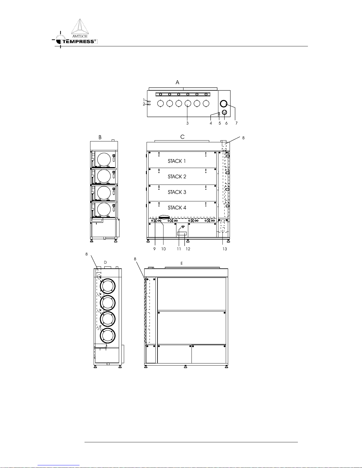
On the next page an outline drawing of a Furnace System, model TS6804 is shown:
FURNACE REFERENCE MANUAL
2-1
DESCRIPTION
Figure 2-1 Outline drawing of a Furnace System, model TS6804
FURNACE REFERENCE MANUAL
2-2

DESCRIPTION
A: top view of the furnace with scavenger
1: Water outlet Bulkhead Swagelok (furnace cooling)
2: Water inlet Bulkhead Swagelok (furnace cooling)
3: Exhaust Furnace
4: Water outlet Bulkhead Swagelok (cooling vacuum-flanges)
5: Water inlet Bulkhead Swagelok (cooling vacuum-flanges)
6: Exhaust scavenger-box
7: Exhaust scavenger-housing
B: sideview of the furnace
C: frontview of the furnace
8: Scavenger box exhaust.
9: Tube switch
10: Key switch control power on-off
11: Mainswitch (lockable in off-position)
12: Mainpowerconnection
13: Excess Temperature Controller
D: view of the loadside of the furnace
8: Scavenger-box exhaust
E: rearside of the furnace
8: Scavenger-box exhaust
2.2 Components of the furnace
• Furnace cabinet
• Scavenger
• Cooling unit
• Fast Cool down
• Heating elements
• Tube (support and sealing)
• Flange
• Furnace Temperature Control
• Power supply
• Main switch assembly
FURNACE REFERENCE MANUAL
2-3

DESCRIPTION
2.3 Furnace cabinet
The furnace is housed in a utilized cabinet of heavy gauge metal construction with a Clean
Room Compatible Polyurethane finish. (See Figure 2-1).
• Optional: Cabinet over-temperature protection sensor on top of the cabinet.
2.4 Scavenger
All 3-stack and 4-stack furnaces are provided with a toxic gas scavenger. Depending on the
application, with or without a front door.
2.4.1
Available models
A) Stainless steel round box with adjustable outlet in the box and one exhaust pipe with
outlet on the top of the furnace on which all boxes are connected. Normally used for
OMEGA-Juniors and all one-stack furnaces.
B) Same as A, however with the provision that service now can be done from the
maintenance room. Each box provided with a separate outlet to the top of the furnace
with adjustable valve. All outlets on the top connected to a manifold. Used for furnaces
with automatically boatloading, cantilever systems etc.
2.4.2
Description of the Scavenger
• Sealing between clean room and service room.
• One exhaust connection on top, there is however also an exhaust connection
possible on the bottom (optional).
• Door for maintenance on the service side.
• Stainless steel round scavengers.
• Each compartment is exhausted and adjustable independently.
• Each compartment has an individual monitor for the scavenger pressure (optional).
FURNACE REFERENCE MANUAL
2-4
DESCRIPTION
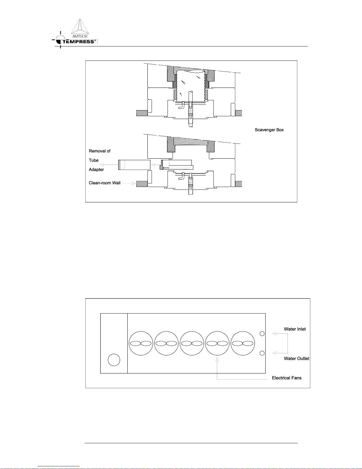
Figure 2-2 Round scavenger box layout (Diffusion)
2.5 Cooling unit
The cooling module is mounted on the top of the furnace. It is a water/air heat exchanger,
with high-efficiency aluminium fins, for optimised surface area. The water quantity
(preferably soft water) is 3-7 l/min, depending on the inlet water temperature. (see Figure 2-1
and Figure 2-3) The electrical fans on top of the module extract the hot air through the
radiator fins and cooled air is blown-out in the room again. The fans start running, as soon as
the main switch of the furnace is switched on.
Figure 2-3 Cooling unit
FURNACE REFERENCE MANUAL
2-5
DESCRIPTION
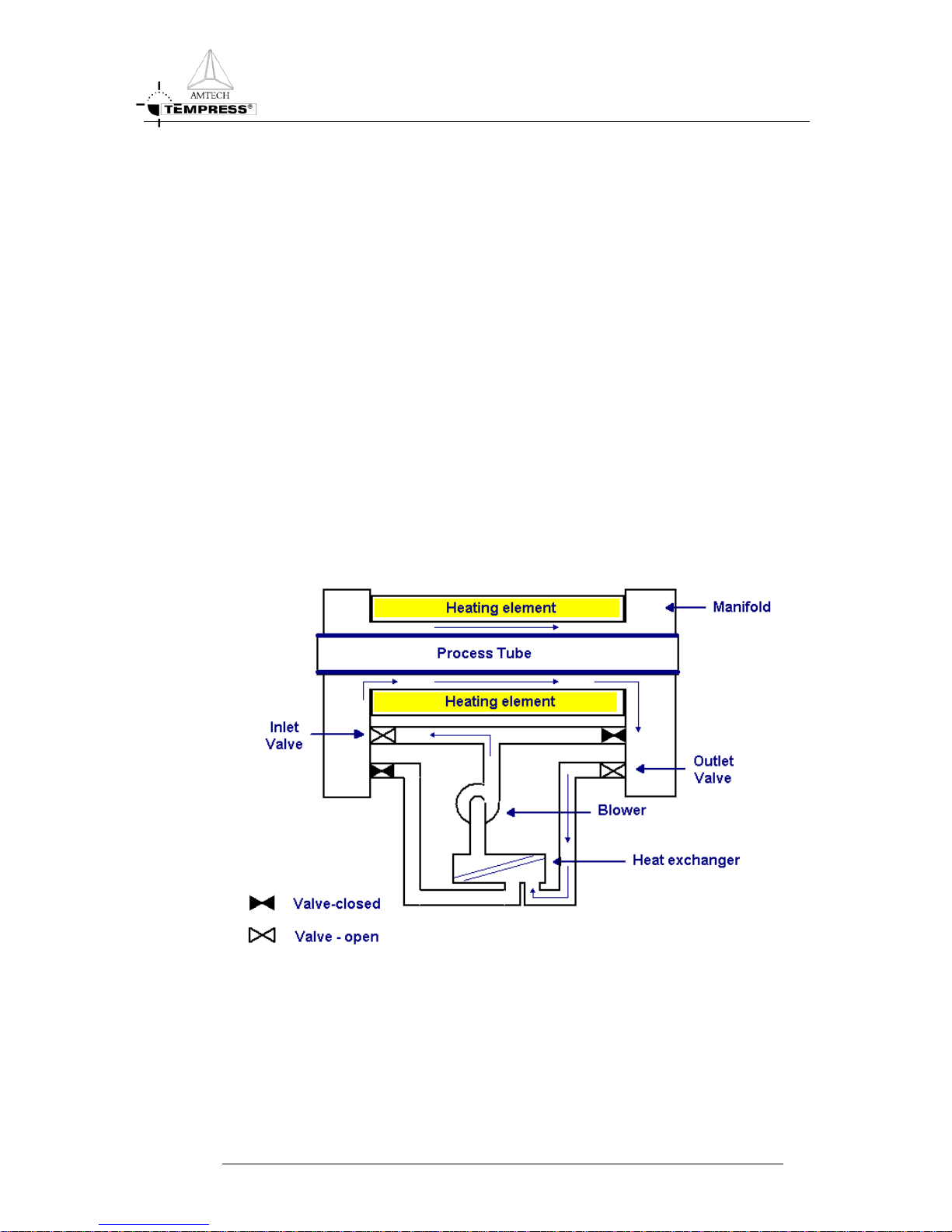
2.6 Fast Cooldown
Air is forced by a blower to travel between the heating element mantle and the outside of the
process tube. The direction of airflow is alternated to achieve balanced cooling faster than
the conventional furnace.
The air used for cooling is re-circulated. It is cooled by a water-cooled heat exchanger built
in, in the furnace cabinet.
The blower is a centrifugal type. The speed is controlled by the DTC and is varied according
to requirements. The blower is connected to the heat exchanger and heating element via
tubing. The Cool down modules (blower and heat exchanger) are both situated behind the
heating elements.
Cooling Process
Cool down is assisted by conditioned air that is forced to flow between the heating element
and the process tube (Figure 2-4). The flow of air is periodically reversed left-to-right; rightto-left to equalize out the cooling effect over the whole wafer load. During cool-down, only
paddle thermocouples are used for temperature measurement. The flowing past the spike
thermocouples makes their use inaccurate.
Figure 2-4 Fast Cooldown principle
Control of the valves and blower during cool-down is done by the DTC which has dedicated
software for the purpose. The cool rate in the temperature table determines the cool down
time and the DTC attempts to maintain this rate over all zones.
FURNACE REFERENCE MANUAL
2-6

DESCRIPTION
At the start of the cool-down step, the DTC checks the current temperature setpoint, the
paddle setpoint (target temperature) and the ramp (slope) to see if forced cooling is
necessary. If it is, the DTC calculates a profile (temperature over time) required to reach the
target setpoint, and sets the blower speed to an appropriate value (determined by an
algorithm). While cooling is in progress, the DTC applies power to the element end zone to
maintain an even cooling “ramp” and to maintain a flat zone.
When the system reaches the paddle setpoint, the blower is ramped down and turned off. At
this point the DTC switches automatically back to cascade control.
2.7 Heating elements (disposacore)
• The furnace contains 3 or 5 zone heating elements of the standard Tempress
Systems specification and are used for optimum temperature characteristics.
• The furnace can contain any of the following heating elements: a multipurpose
Kanthal A-1 coil, a high temp APM coil, an ultra high temp Kanthal Superthal
®
coil,
Low temp white John, MRL heating elements or light Gauge for high/low
temperature applications. Insulation made from high purity, high density, vacuum
molded alumina silica fiber (optional light Gauge). It depends on the process
temperature, which kind of element is used. Custom desired other elements can be
implemented on request.
• Over temperature protection is provided by an Excess Temperature Controller,
connected to separate Thermocouples. See section Error! Reference source not
found.
• Each heating element has its own transformer with isolated coils powering individual
control zones via high-efficiency zero-crossover fired Silicon Control Rectifier (SCR)
power control modules.
• One tube switch per heating element, to shut off one tube only.
• Tube sizes depending on customer demand.
• The combination of the special coil-design, insulation, stainless steel shell and the
DTC guarantees:
• better uniformity
• long lifetime
• energy saving
• no element sagging
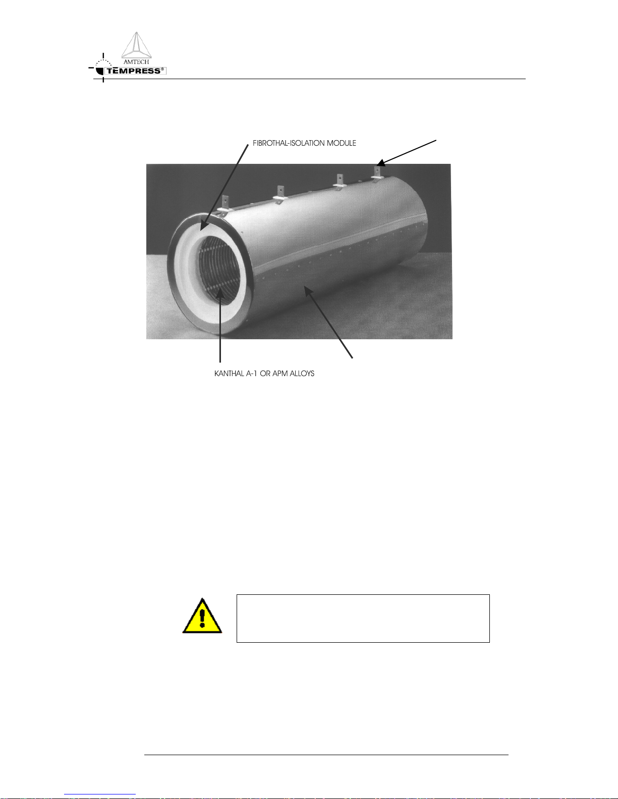
2.7.1
Tube heating module
This module, most of the times multi-zone, consists of a Fibrothal® heating element with
embedded Kanthal alloys and a stainless steel mantle. This module is meant for diffusion
furnaces. See Figure 2-5.
The advantages of this construction are:
• High temperature equability
• Exact temperature profile
FURNACE REFERENCE MANUAL
2-7
DESCRIPTION
• High operating capacity
CONNECTOR FORPOWE
R
STAINLESS STEEL MANTLE
Figure 2-5 Heating element for diffusion furnaces
Life-time and maximum temperature
The typical lifetime of a heating element is 5-15 years but is highly dependent on many
factors. Strong temperature fluctuation and high temperature may reduce the actual lifetime.
Note: Keep in maximum recommended temperature, overshoot will highly increase
the ageing of the heating element.
2.7.2
Heating elements, tube adapters, isolation collars
Kanthal heating elements are isolated with ceramic fiber material. If the material is disturbed,
fibrous dust may be generated. This dust may be carcinogenic.
DANGER
If the temperature exceeds 900°C, silcogene chemicals such
as Kristobalite may be formed. Use appropriate safety
measures. See Material Safety Data Sheet.
General Precautions
• Read the Material Safety Data Sheet and follow the advice and procedures they
contain.
FURNACE REFERENCE MANUAL
2-8

DESCRIPTION
• Wear protective clothing and equipment appropriate for the hazard, this include
overall, hat, dust mask (with a particulate air filter cartridge to DIN 3181 P3),
goggles and gloves.
• Reduce underfoot debris, keep the work area clean.
• Use a vacuum cleaner with a HEPA filter.
• Work in a controlled and careful manner to avoid dust generation and dispersion
Handling
• Never saw, cut or sand silicate fiber material.
• Double-bag, seal and label heating elements for transport.
• Treat heating elements and silicate fiber as chemical waste.
Chemical properties
The ceramic fiber modules contain a high chemical resistance except liquid acids, phosphoric
acids and strong bases. Moistening with water or oil doesn’t influence the properties of
ceramic fiber itself. After drying respectively evaporation, the thermal and physical properties
will be set to their normal conditions.
Be careful with the material in combination with heating elements, because of possible
corrosion
Safety prescriptions
Health Inhalation can cause health injuries. Avoid contact with skin or
eyes.
First aid In case of contacting with skin or eyes: don’t rub, but flush
immediately with ample water.
Protection measures air-exhaust, Dust-mask P2, Goggle and Working clothes with long
sleeves
Labor hygiene wash unprotected skin surfaces thoroughly with water.
Gather working clothes separate.
FURNACE REFERENCE MANUAL
2-9
DESCRIPTION
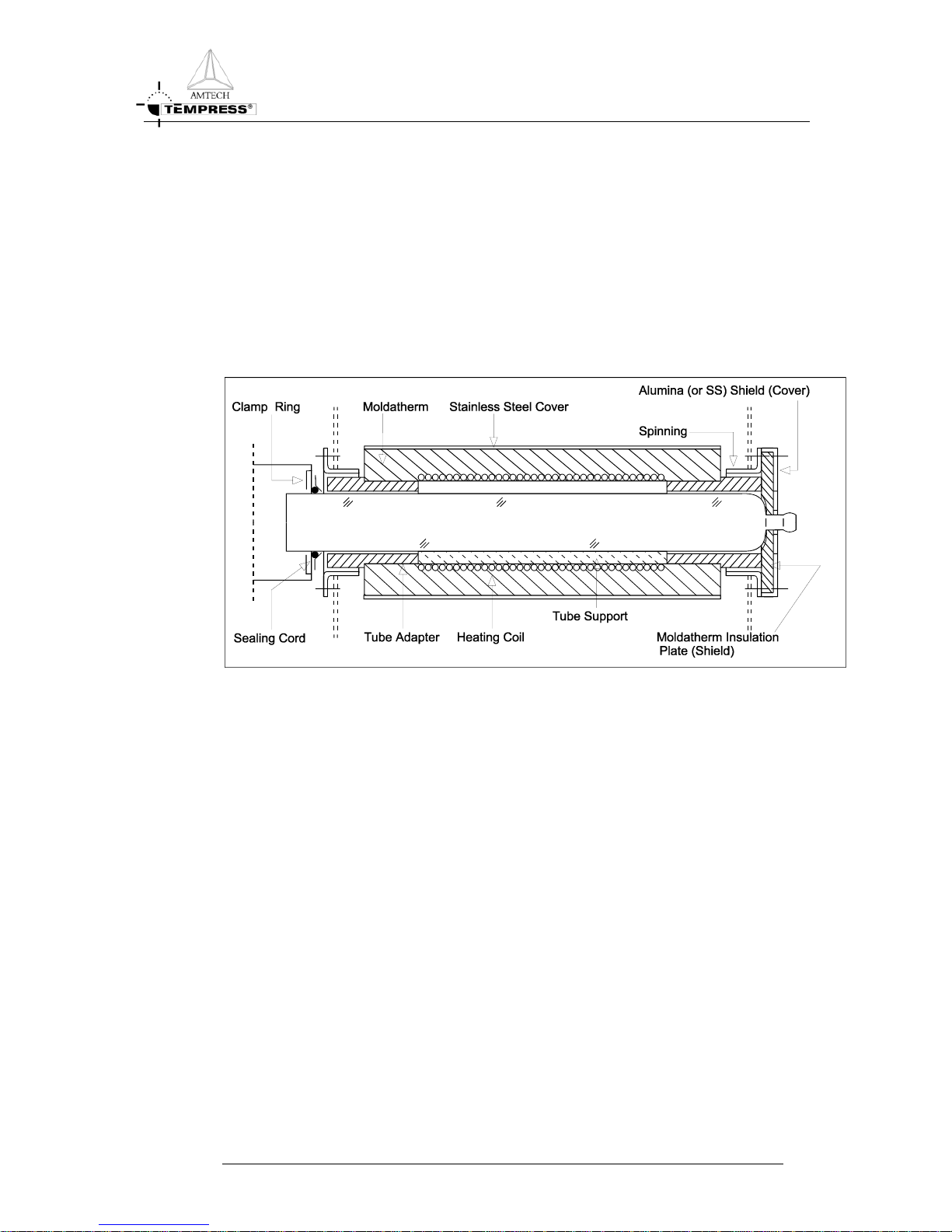
2.8 Support and sealing
• Tubes may be supported by tube supports and centered by tube adapters. The use of
tube supports for high temperature elements is not recommended.
• Radiation heat shield (1 per tube), made of Moldatherm
®
insulation plate and
covered with an aluminium or stainless steel cover.
• Tight sealing between tube and scavenger (optional).
Figure 2-6 Tube adaptors, support and radiation heat shield
FURNACE REFERENCE MANUAL
2-10
DESCRIPTION
2.9 Furnace temperature control
• The Digital Temperature Controller provides master/slave or independent zone
control. It features proportional, integral and derivative (PID) temperature control
functions.
• Digital Temperature Controller, with 3 to 5 zone spike (optional) and paddle control
per tube. Ramping, limit alarms, TC break and power failure alarms and 4
temperature recipes.
• Thermal flatzone is depending on the type of furnace.
• Double spike thermocouples, one for temperature control and one for the Excess
Temperature protection.
• Tripple thermocouples, two are for the spike control (in case of failure of one) and
the third one is for the Excess Temperature protection.
• Optional other control system, see separate manuals.
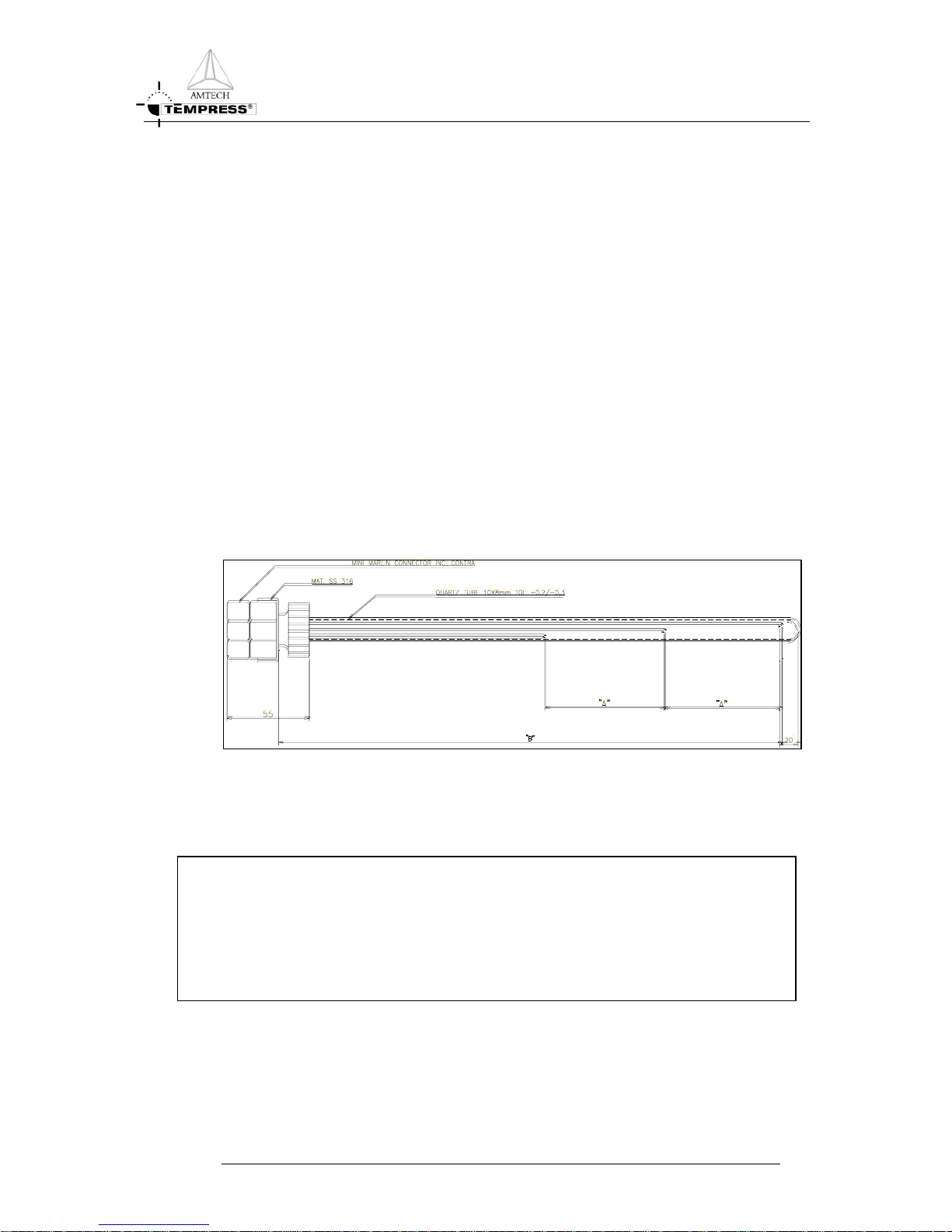
• Thermocouple connections on source or load side of the furnace, for Paddle control
and profiling. See Figure 2-7 and Figure 2-8:
Figure 2-7 Zone paddle profiling thermocouple
Figure 2-8 Double spike thermocouple
FURNACE REFERENCE MANUAL
2-11

INSTALLATION
3.Installation
3.1 Introduction
In this chapter contains a detailed description about the unpacking, installation and
inspection procedures. When the furnace is moved in transit and during final placement at
the customer's facility, care should be exercised at all times.
CAUTION
Transport of the system should be in an upright position
at all times.
3.2 Unpacking
• Before the furnace is unpacked, a visual inspection of packing materials should be
made. If there is evidence of damage during transport, the carrier should be
contacted so that an inspector can be present to verify any damage before the
furnace is unpacked.
• If there is any visible damage, notify Amtech/Tempress Systems verbally and in
writing. This must be done within 24 hours, after arrival of the shipment.
• A forklift truck, with a minimum capacity of 1500 kg, is recommended to be
available to move/carry the furnace in its right place.
CAUTION
The furnace is packed in 2 layers of plastic. The first layer
must be removed outside the clean room. The second
layer must be removed in the clean room.
Unpacking:
• Check off all boxes against the packing list.
• Unpack the boxes one by one.
• Check the contents of the boxes against the collo contents list
• If any damage is visible, then....
CAUTION
Do not dispose any of the packing materials or boxes.
• Release and remove equipment wrappings.
FURNACE REFERENCE MANUAL
3-1
INSTALLATION
CAUTION
Lift or pull the wrappings away from all stainless steel
surfaces. Do not drag packing materials across the
equipment surfaces as this may cause damage.
• Depending what type of packing material is being used; a final de-dusting must be
done before it is put into position. The system has been pre-cleaned before leaving
our factory.
3.3 Installation
CAUTION
During movement, the furnace assembly is slightly
unstable and should be considered top heavy.
3.4 The furnace
CAUTION
Items, described in this paragraph, are the customer's
responsibility.
• Check the bottom side of the furnace for levelers and sagged wires.
• To prevent moving of the furnace during perpendicular lift up, use wooden packing
block.
• Locate the furnace in its final position.
CAUTION
T
he tines of the forklift should extend under complete
width of the furnace when moving.
• Place a spirit-level on top of the furnace. The furnace can then be leveled, by
adjusting the adjustable feet on the bottom of the furnace.
• Locate the loadstation and the gascabinet in their position.
• Level and align the loadstation and the gascabinet with respect to the furnace.
• Install all facilities as indicated on the outline drawing and verify that they comply
with the labeling.
FURNACE REFERENCE MANUAL
3-2
INSTALLATION
CAUTION
Do not turn on any of the services which are
connected. This may only be done in the presence of a
qualified engineer from Amtech/Tempress Systems,
unless prior permission gained from
Amtech/Tempress systems, in writing.
• Final alignment and facility functionality will be checked by the Amtech/Tempress
Systems-engineer.
• The Amtech/Tempress Systems engineer will do purging of all toxic gas lines.
3.5 The scavenger
• Scavenger exhaust (standard) duct has a 108 mm O.D. outlet (check for the right
O.D. the outline drawing). Therefore, install the stainless steel exhaust lines to the
exhaust system. They must meet the state and local regulations for treatment and
exhausting of the toxic, corrosive and pyrophoric gasses.
• The exhaust rate should be around 100 l/min. (per tube level).
3.6 Inspection
• Check for any parts that may have loosened or become free during transit (especially
the electrical connections and power leads), and check all components for damage.
• Check if the tube switches on the furnace are "OFF".
• Check for the correct voltage, on main power connection/label, attached close to the
main power terminals.
• Check if the cabling is correctly connected.
DANGER OF LIFE
High voltage may cause serious injury or may be fatal. It is
essential that all safety guidelines will be followed when
working with high voltage equipment.
FURNACE REFERENCE MANUAL
3-3

START-UP
4.Start-up
4.1 Introduction
After the furnace is installed and leveled correctly, the start-up may begin.
Definition of Chapter Contents:
• Pre-operation checks.
• Burn in elements.
• Tube installation.
• As this is a general start-up procedure for diffusion furnaces, some items are
optional. These items are also marked as optional in the following sections.
NOTE: the start-up of the system is the AMTECH/tempress -field-service
engineersresponsibility.
In case of emergency or system failure, press the EMO-button for a complete system
power down. These red EMO buttons are placed on the upper front of the Remotes
Control Console or loadstation and on the back of the furnace (Optional).
4.2 Start-up
Materials requirement:
• Quartz wool.
• Digital Voltmeter (=D.V.M.).
• Accurate room temperature meter, 1 Decimal Point (=1 D.P.).
• Propan-2-ol (I.P.A.)
• Clean room gloves.
• Clean wipes.
• Clamp type Ampere meter 0-200 Amperes minimum range.
Actual Start-up:
• Place and connect TC's. Note that red is negative. Each ceramic housing for the
thermocouple has two pairs of Thermocouples within it. The wires for each
thermocouple are twisted together.
• Adjust the Thermocouples so that they are just visible (only 2 mm) from inside the
heating element.
FURNACE REFERENCE MANUAL
4-1

START-UP
• For element oxidation, the outer ends of the heating element have to be closed by
using heat resistant insulating material, such as quartz wool (to be provided by the
customer).
Figure 4-1: Spike thermocouple
Figure 4-2: Tube adapter
• Place the tube adapters on a level surface, with the large end down and pack with
quartz wool. Ensure it will not fall from the tube adapters when they are moved and
no foreign material has been incorporated in the quartz wool.
CAUTION
Tube adapters are used to prevent air movement between the
heating element and the process tube. Air movement may be
generated by differential pressures between the cleanroom and the
area outside the cleanroom. Temperature may be substantially
affected by any airflow past the thermocouple junctions.
• Place the tube adapters in the front and in the rear of the heating elements.
• Check if the electrical connections on the heating element are tight. Due to the high
currents in these cables, any loose connections may damage the control circuitry and
the element.
• Check if the cabling is properly connected and check for the correct voltage.
• Check if the terminal strip connections are tightened.
• Check if the water supply and the scavenger exhaust are- connected according to the
outline drawing.
• Check if all system power switches on the furnace are switched off.
• If present, check if the EMO-switches operate correctly.
• Turn on the ‘House Power Supply' to the furnace and check if the Phase voltages are
correct at the main power input connections.
• If present, turn on the main power switch.
FURNACE REFERENCE MANUAL
4-2

START-UP
• Check if the fans, on top of the furnace, are rotating and that the Excess
Temperature unit Power-on indicator is lighted. If one or more thermocouples are
not working, or one or more LED’s are lightning, refer to the section in the
maintenance chapter. Do not proceed further until conditions are corrected.
Note: If gascabinet, gassystem and loadstation are fitted, then power will be applied to
them, when the tube switches are turned on.
• Turn on the tube power switches, one by one. After turning each switch, ensure that:
• The tube indicator lamp is lighted.
• The temperature controller illuminates.
• The process controller illuminates.
• The touch panel illuminates (optional).
• If there are failures, see the Maintenance Chapter.
• Burn-in and oxidation of elements (see item 0)
4.3 Fast Cooldown
For a pliable movement of the valves, the pressure to close the valves in the manifolds needs
to be adjusted between 1 and 2 bar.
Note: More than 2 bar results in unnecessary high closing pressure.
WARNING
In case of unauthorized break of seal of the pressure
relief valve, Tempress Systems Inc. cannot accept any
responsibility in case of any damage on the system.
4.4 Burn-in and Oxidation of an Heating element
DANGER OF LIFE
In case of touching the Isolation Material always
consult the technical data, item Error! Reference
source not found. (Safety enclosure Fibrothal
®
)
The heating element has to be given an oxidation treatment to protect the element and
increase its lifetime. Before execute the steps as listed below, it is essential that the
operator/engineer is fully conversant with the operation of the temperature controller. The
furnace can be equipped with different types of elements. Follow the procedure as described
below.
FURNACE REFERENCE MANUAL
4-3

START-UP
A. Use the following steps for standard Kanthal A1
or APM Heating elements:
• Heat it up from ambient up to 6000C with maximum power/slope value.
• Testing of the Redundant Thermocouple Excess Temperatures, in each zone, by
giving a setpoint of 600 degrees, on the “Excess Temperature Controller".
• The Excess Temperature Controller is designed to guard the temperature, measured
by thermocouples. If, an overtemperature occurs, an alarm appears on the
touchpanel. (For further information, see the Flat Panel Operating Manual and item
Error! Reference source not found.)
• Reset the Excess Temperature Controller set point to 1250
0
C.
• Allow the furnace to soak at this temperature for at least 12 hours at 600
0
C.
• Increase the temperature setting up to 1200
0
C, again with maximum power/slope.
• Allow the furnace to soak for a minimum of 2 hours.
• Reset the controller to 25
0
C.
• Turn off the tube power switch.
• Allow to cool to ambient.
• After cooling down (5.), the system is now ready to operate; the pre-cleaned process
tube can be installed.
B. Use the following steps for MRL HELIX heating elements
:
• Once the HELIX element is installed, insert the spike thermocouple into the
chamber.
• The Thermocouples should extend well into the element, insure they are visible.
• Pack the ends of the element, eliminating open spaces at either end.
• Set the control system for 400
0
C, and turn on power. Observe the heat-up.
• Once the furnace is in control at 400
0
C, start ramping it up at 100 per minute, or if
the system does not have ramping capability, increase the set point in 100 degree
increments to a final set point of 1100
0
.
• Hold the HELIX at 1100
0
for a minimum of 8 hours. Allow the element to cool
down. The element coil now has a good, protective oxide coating and is ready for
process tube installation.
FURNACE REFERENCE MANUAL
4-4

START-UP
4.5 Installation of the Quartz Tube
Follow the procedure as described below for installing a Quartz Tube:
• Unpack the quartz tube and inspect for any type of damage. If any damage is visible,
then... (for further information, see item 3.2).
• Clean the quartz tube in a diluted solution of HF and de-ionized water concentration
(1% till 5% HF).
• Place tube support in the heating element.
• Place tube adapters at both sides of the furnace.
Figure 4-3: Position of the thermocouple
• Disconnect the clamp spring of the thermocouple. Withdraw the thermocouple.
Check at the inside of the heating element that when the process tube will be
installed, it won't touch any thermocouple at all.
• Don't withdraw the thermocouples too far, so that the wires are bending too sharp.
These wires break very easily.
• Slide the process tube very carefully inside the heating element, till the right position
has been achieved.
• Place the radiation shield and the cover. After the radiation shield has been installed,
the quartz tube must be pressed firmly to the radiation shield.
FURNACE REFERENCE MANUAL
4-5

START-UP
• Check if there are any gaps between the process tube and the tube adapters and
between the radiation shield and the quartz tube. If there are gaps, fill them up with
heat resisted insulating material, such as quartz wool.
• Push the thermocouple back, till it touches the quartz tube (seeFigure 4-3). When the
thermocouple is placed correctly, the pressure spring can be placed on the
thermocouple. Check if the pressure spring is in its right position (see Figure 4-3). If
not, then adjust it. The furnace is now ready to be heated up carefully.
4.6 Test and Calibration Procedure
See Technical Manual DTC, chapter 4.0
4.7 Pre-Cleaning of the Process Tube
Process Tubes supplied by Amtech/Tempress have been pre-cleaned by our supplier, but it
is recommended that a further clean is carried out before installing.
1. In case of Quartz process tubes:
They may be cleaned by using a solution of 1: 10 HF/Dl-water, for 2-3 minutes. After
etching, the tube should be rinsed in DI-water sufficiently to remove all traces of the acid and
dried with dry nitrogen.
2. In case of Sic process tubes (Crystal) and Paddles:
Some process tubes and liners may have a Zircon coating on the OD. It is not
recommended to wet clean these products with Hydrofluoric (HF) acid. This will cause the
coating to peel and flake off.
To prevent the potential of accidental breakage, the components should not be subjected to
high temperatures immediately after wet cleaning. Components should be allowed to dry at
room temperature for 12 hours or longer. After room temperature drying, it is preferred to
insert components at 300
0
- 4000C for 1-2 hours, and then use normal 3000C/hr ramp-up
cycle.
Initial Room Temperature Clean:
• Use normal quartz cleaning procedure including HF and/or NH
2
OH solutions.
Dilute HF solutions have an equal amount of HCL, eg.: HF:HCL:H
2
O=1:1:4.
• Do not use concentrate HF and HNO
3
combined.
• Rinse in DI water and dry air.
Initial High Temperature Clean:
• Heat to 50
0
C higher than intended process temperature or higher if practical
(cleaning/time:1100
0
C/48hr, 1200 0C/16hr, 13000C/8hr).
• P-tubes: Heat up to desired cleaning temperature in 300
0
C steps with 10 minute hold
at each step of stabilization.
FURNACE REFERENCE MANUAL
4-6

START-UP
• Paddles and wafer boats: Insert at 500 to 800
0
C and ramp up.
• TCA-Run dry O
2
at 4 liters/min. N2 carrier gas at 300 ml/min. through bubbler at
30
0
C for time indicated.
OR:
• HCL-Run dry O
2
at 4 liters/min. and HCL at 250 ml/min. for time indicated.
• Oxidize after TCA or HCL for 30 min. with dry O
2
at 4 liters/min.
Qualification:
• Use CV measurement or whatever is prescribed for the process involved.
• Repeat cleaning procedures as necessary.
Removal of glasses or dopants or oxide:
• Etch diluted HF at room temperature as long as needed.
Removal of Si
3 N4
:
• Conservative:
Etch in concentrated HF at room temperature as long as needed. Expect about 50
Å/min. removal rate.
• Aggressive:
Etch in 1:1 concentrated HF and HNO
3
. Removal will be much faster (It is essential
to avoid exposure of bare Crystal to this solution. Once Si
3N4
is removed, Si will
quickly be etched out of the component, malting it porous and weak. The best
approach is to leave a slight layer of Si
3N4
.).
Removal of Polysilicon:
• Conservative:
Etch in 50 parts HNO
3
, 1 part HF and 20 parts DI water.
• Aggressive:
Proportion of HF may be increased for faster removal, but care should be exercised
as with Si
3N4
removal above, and leaving a thin layer of Poly is a good approach. It
may also be worthwhile to deposit a layer of Si
3N4
on the components before service
in a Poly operation since the Si
3N4
is more resistant to HF:HNO3 and will allow a
margin of error in etch time for Poly removal. Also note that Poly will not flake off
from silicon carbide as it does from quartz so some residue is normally accepted.
WARNING
If paddle handles are not precoated with Si
3N4
or
Poly (by separate operation with handles in flat
zone), it will be necessary to provide protection, such
as with a teflon sleeve, during etching.
FURNACE REFERENCE MANUAL
4-7
START-UP
General information:
• Relative thermal expansion rates: SiC 4.8; Poly 3.8; Si
3N4
2.7;SiO2 0.5
• Typical cleaning frequency for Si
3N4
is every 100 cycles (based on 1000 Å per cycle
or 100,000 Å build up).
• Typical cleaning frequency for Poly operations is every 40 cycles (based on 5000 Å
per cycle or 200,000 Å build up).
• Typical cleaning frequency for LTO operations is every 10 cycles (based on 5000 Å
per cycle or 50,000 Å build up).
CAUTION
For Atmospheric Oxidation Processes it is
recommended to run a TCA-clean and oxidation
before starting processing.
3. In case of other material then quartz or Sic;
Please refer to "Vendors' cleaning-procedures".
4.8 Automatic profiling procedure
4.8.1 Automatic profiling procedure
This is a general automatic profiling run procedure, according to the Amtech/Tempress
standard. Automatic profiling defines the relation between the temperature inside the tube, as
measured by the paddle ThermoCouples (TCs), the temperature outside the tube, as measured by
the spike TCs, and the required power output. Automatic profiling offers improved temperature
control and more accurate temperatures during process.
4.8.1.1 Introduction to profiling
The desired temperatures are defined in the Certifications-submenu-Temperature Controller
Certifications-submenu-Profile Temperature Table assuming a touchscreen is used. If the
TSC-2 software is used the profile temperature table can be found at Tube level – System
menu – DTC Setup – Profiling Recipes.
Four columns contain the Profile Recipe PF, the Paddle Setpoint, the Spike value and the Output
power. Every column is subdivided per temperature zone, every row corresponds to the
specific Profile Temperature Recipe.
After this relation has been established, the normal process run will use the Paddle Setpoint as
the final value to which the temperature must be controlled. It will use the Profile
Temperature Table to calculate the required Spike Value and this value will be used as the
control signal to the DTC software control loop. The Power Output is only used in case of a
FURNACE REFERENCE MANUAL
4-8

START-UP
Spike TC failure during normal process. It will allow the process run to finish using the Power
Output instead of the Spike Value saving a valuable process batch.
Four (4) different Profile Temperature Tables (A-B-C-D) are available for use in different
process environments, such as atmospheric-vacuum or dry-wet. The temperatures defined in
one profile temperature table are used in the other 3 tables as well.
CAUTION
IT IS NOT POSSIBLE TO HAVE A DIFFERENT SET OF
TEMPERATURES IN ONE PROFILE TEMPERATURE
TABLE COMPARED TO ANOTHER
CAUTION
THE PROFILE TEMPERATURE RECIPES MUST BE IN
ASCENDING ORDER.
The procedures for your system may deviate from this general procedure. This depends on
the kind of processes and/or system, which has been purchased. For example, in a manually
loaded system the message BOATOUT is not applicable.
4.8.1.2 Profiling recipe setup
LOAD/UNLOAD
The process starts with step 0 LOAD/UNLOAD status, this means in the safety status. It is
only in this step that a different process recipe can be selected.
After starting, the step numbers are executed sequentially. The sequence can be interrupted
by active branch or abort conditions. An automatic or operator initiated abort causes the
programmed abort recipe to be executed as if it was a normal recipe. At the end of the abort
recipe the system returns to step number 0 of the original process recipe. If no abort recipe
has been specified the automatic or operator initiated abort instruction will result in a direct
jump to step 0 of the original aborted process recipe.
BOATOUT
In this step the boat loader moves to the boat out position (10 mm) with the programmed
speed (mm/min). If the oscillation field is 0 (zero) the boat stops when it reaches the
position, otherwise the boat loader oscillates at the programmed speed with an oscillation
span of 12mm. The latter is only applicable for wheelpaddles in a CVD system.
LOAD WAFERS
In this step the system waits for the operator to load the wafers in the boatloader. A sonalert
alarm will sound. Put as many wafers in the boatloader as would normally be used during
process. When loading is done press <START>.
FURNACE REFERENCE MANUAL
4-9

START-UP
Note: do not touch the wafers. If a wafer is touched or dropped on the floor, don’t use this
wafer for processing.
BOAT IN
In this step the boatloader moves to the boat in position (system dependent) at the
programmed speed (adjusted in mm/min).
STABILIZE
In this step the system will be settled to simulate the desired process environment. This is
important for accurate temperature control. The heat transfer from heating element to tube
to wafers and paddle will (slightly) differ for atmospheric and low pressure environment. The
same is valid for a dry or wet environment. Typically 2 tables are used in an atmospheric
process tube, one for ‘dry environment’ and one for ‘wet environment’. For LPCVD
applications only ‘low pressure environment” is sufficient and can be obtained using N
2
as
the ‘process gas’.
PROFILING
The system is given 3 hours (default) to reach a selected temperature and keep the setpoint
within limits for 20 minutes.
The temperature is selected from the Profile Temperature Table (default A) as a Profile
Temperature Recipe. The system will control the temperature until the setpoint has been
reached. When the setpoint has been reached within limits a timer is started (Default limit is
0.5
o
C, changeable in Certifications-submenu-Temperature Controller Certificationssubmenu-Tube configuration-maximum profile deviation on a touchscreen, for TSC-2 it
can be found at Tube level – System menu – DTC Setup – DTC configuration – ProfDev
column. Do not forget to write to DTC after changing in TSC-2).
For 20 minutes the temperature needs to be within these limits. If the temperature falls
outside the limits the timer is reset. After 20 minutes of successful stabilization the Spike
Value will be stored in the Profile Temperature Table (default A) first. Then the required
Power Output will be stored and the Profiling Step is finished. Subsequently the system will
continue to the next process step.
The Power Output will be used automatically to finish a normal process run in case of a TC
failure.
If, for some reason, the automatic profiling is not finished after 3 hrs a Wait for temperature
alarm will be generated and the system will wait for either the temperature to reach the
setpoint within limits or an operator to abort the process.
COOLDOWN
After the automatic profiling run the system will cool down. The temperature will ramp
down in the adjusted range in
0
C/min.
STANDBY
The system is waiting for the operator to return. This is especially convenient when the
automatic profiling run has been started over night. The system is put into a safe condition.
The operator needs to press <START> to continue. Optionally this step can be removed to
have the system automatically take the wafers outside the tube.
BOAT OUT
In this step the boat loader moves to the boat out position (10 mm) with the programmed
speed (mm/min). If the oscillation field is 0 (zero) the boat stops when it reaches the
position, otherwise the boat loader oscillates at the programmed speed with an oscillation
span of 12mm. The latter is applicable for wheelpaddles in a CVD system only.
FURNACE REFERENCE MANUAL
4-10
START-UP
UNLOAD WAFERS
In this step the system waits for the operator to unload the wafers. A sonalert alarm will
sound. When unloading is done press <START>.
After reaching the END command of the profile process recipe, the recipe will return to step
0, the safety status. Only in this state another process recipe can be selected.
4.8.2
automatic profiling preparation
This is the automatic profiling preparation procedure, according to the Amtech/Tempress
standard. Automatic profiling defines the relation between the temperature inside the tube, as
measured by the paddle ThermoCouples (TCs), the temperature outside the tube, as measured by
the spike TCs, and the required power output. Automatic profiling offers improved temperature
control and more accurate temperatures during process.
4.8.3
Paddle TC installation
a) First, the DTC needs to use the paddle TC signals instead of the spike TC signals.
This is done in the Tube control-sub menu-Assign control zones. Default the paddle
inputs are assigned to control zone 0, meaning the paddle TC inputs are not used for
temperature control. Changing the paddle inputs 1, 2, 3, (4 and 5 if applicable) to
control zones 1, 2, 3, (4 and 5) respectively will allow the DTC to use the paddle TC
signals.
CAUTION
The paddle TC consists of 3 (5) TC wires in a ceramic tube,
covered by a quartz tube extreme care is required to prevent
breakage.
b) Secondly, the paddle TC needs to be checked for correct functionality. Put the
paddle TC connector labeled 1 into the connector labeled 1 on the rear of the
furnace (old systems have connectors at the front side of the furnace) while keeping
the paddle TC outside the furnace. Check on the touchscreen in Monitor Menu-sub
menu-Main Detail Status that the paddle Actual value changes from 1499.9 (means
open connection) to room temperature. Repeat this for all other connectors 2 to
3(5).
c) Thirdly, use a heatgun to test all 5 paddle thermocouples for correct functionality.
Aim the heatgun at one particular TC for about 30 sec and monitor the temperature
rise. If the temperature increases approximately 20
o
above room temperature the TC
is working properly. Remove the paddle TC connectors 1-5 from the rear connectors
and put the paddle TC in a secure place.
d) Finally make sure the paddle TC number 3 (center TC) is aligned to the center spike
TC. Measure the distance between center spike TC and the end of the profile TC
connection pipe on the tube. Adjust the PTFE paddle TC connector to the
measured distance and tighten it.
e) Put the paddle TC gently inside the tube.
FURNACE REFERENCE MANUAL
4-11
START-UP
CAUTION
Extreme care is required to prevent breakage of profile TC or
profile TC connection on process tube.
4.8.3.1 Profile recipe selection
First, the desired profile temperatures need to be edited into the Profile Temperature Table.
a) Go to Certifications-submenu-Temperature Controller Certifications-submenu-
Profile Temperature Table on the touchscreen. Use Tube level – System – DTC
Setup – Profiling recipes for TSC-2. Put the desired profile temperatures in
ascending order. Do not forget to fill in for zones 4 and 5 if applicable.
b) Exit to the main menu by pressing Esc several times. Go to Recipe Menu (Recipe
for TSC-2) and edit the recipe PROFILE.
c) Find the steps with ‘Time 03:00:00’, ‘Temp. Profile Recipe xx’ and ‘Wait for Temp.
to reach setpoint’ commands and verify the correct temperatures. Adjust the recipe
by adding or deleting the appropriate steps if so required.
d) Store the recipe by exiting the Recipe Editor with Esc and confirm to store. Return
to Main Menu with Esc several times. Make sure to Write to DTC when using TSC-2.
e) Go to Tube Control Menu-submenu-Select a process recipe. Select the PROFILE
recipe. Use Operations for TSC-2.
4.8.4
Automatic profiling RUN
a. Select the PROFILE recipe.
b. Start the PROFILE recipe. Put the amount of wafers on the paddle that
approximates the process load.
c. Wait until the system has reached step 0 (STANDBY) again or indicates an operator
action is required.
d. Unload the wafers.
e. Unassign the Temperature Control Zones
f. Remove the Profile TC
CAUTION
Thermocouple is very hot!
g. The system is now ready for processing
FURNACE REFERENCE MANUAL
4-12

START-UP
4.8.5
Summary automatic profiling
a. Determine the required Profile Temperatures and edit the appropriate Profile
Temperature Table and PROFILE recipe.
b. Prepare the system using the Automatic Profiling Preparation Procedure. This places
the Profile TC and assigns the control zones.
c. Start the PROFILE recipe using an approximate process load.
d. Unload the wafers when finished.
e. Unassign the Temperature Control Zones and remove the Profile TC if required.
f. Read new profile table from DTC to PC
g. Print new profile table and compare with previous profile table. Large variations
(>10
o
C) in spike TC values indicate too long profiling interval, increase profiling
frequency.
h. The system is now ready for normal processing.
FURNACE REFERENCE MANUAL
4-13

MAINTENANCE
5.Maintenance
5.1 Introduction
With this system, maintenance is reduced to a minimum. It is only necessary on the rare
occasion when a part fails. Replacement of parts is described in the following paragraphs.
5.2 Heating Element Coil
• The heating element must be replaced by a new one, when it is out of order.
• Preceding the installation of a new heating element, remove the quartz tube and
thermocouples first (take it out of the furnace).
• After installation, beware of following the procedure, described in item 4.2 again.
Installation of a new heating element (exchange of the heating element) must be
done in the following order:
• Turn-off power to tube level (using the tube switch).
• Place safety marker on tube switch, preventing someone switching on again (meet
customers facility safety requirements).
• Close the ballvalves in the gassource cabinet at shelve (tube) level.
• Remove outer panel at tube level, by turning the DZUS-fasteners at the left- and
right side of the panel.
• Open 'tunnel' in front of heating element in which the thermocouple wires are
connected.
• Disconnect the clamp spring of the connected thermocouples.
• Disconnect the thermocouple wires from, these thermocouples.
• Withdraw carefully, using gloves, and place them at a safe and clean place to prevent
damage and remove the insulating cord (see Figure 4-3, page 4-5).
• Disconnect the gas inlet line to the process tube.
• Remove the frontflange assembly (only mounted for LPCVD) and when present,
also the backflange.
• Remove process tube from the furnace tube level (using gloves) and put it at a safe
and clean place.
• Remove tube adapters and the tube support.
• Remove the front support of the heating element, when necessarily.
• Disconnect the thermocouple-connection cables from the terminal blocks.
• Remove 'tunnel' from the thermocouples.
• Bend the compensation cables from the thermocouples carefully to the side.
FURNACE REFERENCE MANUAL
5-1

MAINTENANCE
• Remove straps and power cables from the heating element
• Lift the heating element from the support and remove it carefully.
• Place the new element and follow the instructions, as described above, in reverse and
adjust the heating element. After the adjustment, the procedure as described in item
0 (
Burn-in and Oxidation of an Heating element), must be followed again.
The adjustment of the heating element must be done as follows:
• Adjustment of the base height through the front support, mounted on the front and
on the back of the heating element (see figure Figure 5-1).
• Adjustment of the heating element, to reach a correct position may be done by the
heating element support, mounted on each side of the heating element. By moving
them away from the heating element, the heating element will go down. Moving
them towards the heating element will lift it up.
• If a correct position is achieved, the tube support can be placed smoothly.
Figure 5-1 The heating element adjustment
FURNACE REFERENCE MANUAL
5-2

MAINTENANCE
• The heating element must be placed so that the thermocouple-holes are right in
front of the holes of the 'tunnel’ and the powertraps are above the tunnel.
• If the heating element is in the final position, it will be held in its position through
straps.
5.3 Heating elements
• First as described in item 5.2, remove the process tubes.
• Before removing a heating element, be sure that the power switch is in the "OFF"
position.
• Open the furnace doors and remove the thermocouples and the thermocouple
support duct. Beware of withdraw the thermocouples too far, so that the wires will
bend too sharp. As described before, they can break very easily.
• Disconnect the bolts on the power terminals of the heating element.
• Lift out the heating element.
• After installation of the new heating element, follow the start-up instructions as
described in item 4.2 and the heating element adjustment as described in item 5.2.
• Connect the bolts on the heating element. This must be done very carefully!
• Use two box-end wrenches when tightening the bolts on the power terminals of the
heating element. This action is necessary to preclude stresses can fracture the lead at
the element weld.
5.4 The SCR-Module
Use the following procedure for replacement:
• Turn off the power of the entire furnace.
• Open the panel, at the bottom of the furnace, in which the SCR-Module has to be
replaced.
• Remove the DTC from the door and place it on a safe and clean area.
• Two side-locks (on the top right and left side of the powerpack-stand) must be
opened, so that the powerpack-stand can be moved to the front.
• Lift the powerpack-stand out of the rail and place it on the floor in front of you.
• Remove the wires, connected to the interconnection board, from the defected SCR-
Module to the new SCR-Module.
• When a broken SCR-Module has to be replaced, the new one can be put into its
place, by bringing heatconducting paste on the contact surface of the SCR-Module
and Heatsink.
• Put everything in its place as described above.
FURNACE REFERENCE MANUAL
5-3

MAINTENANCE
• The furnace can now be used again.
5.5 Heat Exchanger
If the heat exchanger is leaking or clogged, replace it by a new one. Check monthly if all fans
are running smoothly. If one fan is out of order, it can be replaced at the next convenient
moment.
Replacement must be done in the following order:
• Turn off the power of the entire system.
• Shut off the cooling water.
• Remove the cooling water out of the coolings.
• Unscrew the fastening screws.
• Move away the fanplate.
• Disconnect the connector of the fans.
• Replace the fanplate by a new one.
When replacing a fanplate, beware of the 'Swagelock' tube fittings. These have to be
re-tightened as follows:
• The connections can be disconnected and re-tightened many times. The same
reliable, leak-proof seal can be obtained every time the connection is remade.
• Tighten the nut by hand.
• Rotate the nut to the original position with a wrench (An increase in resistance will
be encountered at the original position).
• Then tighten slightly with the wrench. The original position will generally be about
1/4 turn for 1/4' to 1/2' tubing (Smaller tube sizes will takes less tightening to reach
the original position, while larger tube sizes will require more tightening. The wall
thickness will also have an effect on tightening).
FURNACE REFERENCE MANUAL
5-4
MAINTENANCE
5.6 Tube change
CAUTION
Use cleanroom gloves for handling quartz.
CAUTION
No special directions are necessary to remove process
tubes. However, after every tube change, if a gap exists
between the process tube and the adapter, it must be
repacked with fiberfax wool This will prevent air
movement within the furnace and resultant temperature
cycling.
CAUTION
Use only cleaned quartz tube, paddle and cleaned profile
TC.
5.7 Tube change diffusion system tubes
The tube exchange is required at the moment there has been a deposition of approx. 20
microns. This however is strongly depending on the particle additions at processing. In case
the particles exceed the specifications the tube should be exchanged.
At every tube change the following has to be done:
1. Cool the system down to room temperature.
2. Remove the cantilever paddle. Must be cleaned.
3. Open the door to the heating element and pull the Thermocouples 5 cm out.
4. Take the Profiling TC out of the tube. Must be cleaned.
5. Remove the external torch if applicable. (See External Torch Manual)
6. Remove the tube adapters and the insulating endcap and stainless steel radiation shield.
7. Pull the process tube gently, 2 engineers should be present to guide the tube, and assure
it does not scratch.
To place the tube back in the system use the reverse procedure.
FURNACE REFERENCE MANUAL
5-5
MAINTENANCE
5.8 Tube change LPCVD and vacuum system tubes
CAUTION
Use cleanroom gloves for handling quartz.
The tube exchange is required at the moment there has been a deposition of approx. 20 microns.
This however is strongly depending on the particle additions at processing. In case the particles get
above spec, the tube should be exchanged.
At every tube change the following has to be done:
1. Cool the system down to room temperature.
2. Remove the cantilever paddle. Must be cleaned.
3. Untighten the screws of the front flange of the process tube.
4. Open the door to the heating element and pull the Thermocouples 5 cm out.
5. Take the Profiling TC out of the tube. Must be cleaned.
6. Remove the Pressure Switch.
7. Remove tube adapters and radiation heatshields.
8. Remove the ball joint clamp and the clamp of the vacuumline and move the vacuumline
away. Vacuumline must be cleaned.
9. One engineer should be at the loading side and one at the rear of the system.
10. Pull the tube 2 cm to the rear so that the engineer at the loadside can take the O ring
from the tube. Front flange must be cleaned.
11. Gently pull the tube out of the system, while the engineer at the loadside guides the tube
out, while lifting it up so it does not scratch on the element. Tube must be cleaned.
12. At each tube change that is done after a number of process runs, the Mass Vac Dust trap
must be cleaned, and all new filter elements must be fitted!
13. When putting the system back together again, use the opposite procedure and:
14. Use only new O-rings on all the seals, flange, ball joint, profile TC, vacuum line, etc.
15. Clean all the vacuum flanges and o rings with isopropyl alcohol.
16. Use only cleaned quartz tube and cleaned profile TC.
17. Check the adjustment of the vacuum atmosphere switch.
18. Check system base pressure - must be < 5 mtorr at 20 degrees C.
19. Check system leakup rate - must be < than 10 mtorr / min.
20. After every tube change the system must be profiled and after profiling a coating run
should be done (for deposition systems only) and the system profiled again after coating.
21. Check system leakup rate at standby temperature.
22. Check system for any alarms.
23. System is ready for processing
FURNACE REFERENCE MANUAL
5-6

MAINTENANCE
5.9 Preventive Maintenance
Maintenance of the furnace is divided in three sections. These are daily maintenance, monthly
maintenance and yearly maintenance.
On the next pages a list with the three sections dealing about the maintenance is
inserted:
Daily Maintenance:
Check if element is still working property (check if there is an alarm on the
display of the controller).
Check temperature stability and temperature control of each stack during
ramp up or down.
----------------------------------------------------------------------------------------------
----------------------------------------------------------------------------------------------
Monthly Maintenance:
Check if the excess temperature protection is still working (check setpoints
for each zone).
Check if the tube adapters are still properly fitting.
Check the process tube.
Check if the load doors (if applicable) are still in a good condition.
Check if the o-rings are still in a good condition.
Check if the indicator light (power on) is working.
Check if there is any visible damage due to heat losses at the furnace outer
ends.
Check the flow of the cooling water through the heat exchanger.
Profile furnace minimal once a month.
Record all spike values of new profile and compare with previous values.
In case values deviate more than 5 °C under the same profile circumstances,
check voltages and thermocouples.
Check exhaust fans on proper functioning.
FURNACE REFERENCE MANUAL
5-7

MAINTENANCE
Yearly Maintenance:
Switch furnace off
Make sure all voltages are off
Check all wiring for loose connections of the power cables and all strips.
Check the amount of water flowing through the heat exchanger.
Remove spike TC’s. Remove quartz tubes, tube adaptor, etc.
Clean inside of heating element with vacuum cleaner. Clean lower electrical
compartments with vacuum cleaner.
Check all wires on terminal strips on tightness.
Tighten all powercables with a wrench.
Tighten more than hand tight on elements powerpacks and transformers.
Check TC’s on performance
Check welding of TC tip with magnifier glass (should be shiny not dull).
After reassembling of all parts calibrate DTC according technical manual
page 25 a/o. (chapter 4).
Reprofile furnace according stored profile recipes.
----------------------------------------------------------------------------------------------
FURNACE REFERENCE MANUAL
5-8

CALIBRATION / ADJUSTMENT
6.Calibration/Adjustments
• Spikes will be calibrated with the paddle thermocouples (Automatic profiling) (for
more information, see the DTC-Technical Manual).
• Change only the PID-adjustments if the furnace temperature isn't stable (for more
information, see the DTC-Technical Manual).
• Adjustment of the Excess Temperature controller, adjustment of the setpoint to the
process temperature (for more information, see item Error! Reference source not
found.).
• In case of an Digitric 500 Overtemperature Security, instead of an Excess
Temperature controller look in paragraph Error! Reference source not found..
FURNACE REFERENCE MANUAL
6-1

TROUBLE SHOOTING
7.Trouble Shooting
PROBLEM: POSSIBLE CAUSE AND SOLUTION (-S):
1. Excess Temperature alarm:
• Thermocouple break (one of the LED’s will be
lighted).
• Setpoint of the Excess Temperature is lower
then the setpoint of the Temperature Controller.
• Overtemperature of a zone
2. Alarm sounds (buzzer):
• Consult touch panel read out.
• The touch panel will indicate the location of the
problem. (For more information, look at the
controller manual)
3. Temperature too low:
• SCR is out of order/fuse out of order
• Power failure
4. Temperature Controller alarm:
• Thermocouple break:
• Temperature does’nt reach the
setpoint:
• Temperature does’nt be stable:
• Replace the thermocouple
• Wrong programming information in the digital
temperature controller
• Wrong programming information in the digital
temperature controller
• Draft on the thermocouples
FURNACE REFERENCE MANUAL
7-1
 Loading...