

Page 1

Touchscreen Reference Manual
Tempress® Systems, Inc.
Touchscreen manual
M440_01 January 2004
Page 2

This page intentionally left blank
Page 3

TABLE OF CONTENTS
Table of contents
1. Introduction .......................................................... 1-1
2. System specifications ......................................... 2-1
3. Installation ............................................................ 3-1
3.1 Installation into a new furnace .................................................. 3-1
3.2 Upgrading the front panel display ............................................. 3-1
4. Screen Hierarchy.................................................. 4-1
5. Data Input.............................................................. 5-1
5.1 Using the qwerty keyboard ....................................................... 5-1
6. Operation Menu’s................................................. 6-1
6.1 System controller ...................................................................... 6-3
6.1.1 Access control ........................................................... 6-4
6.1.2 Access: start on another recipe STEP....................... 6-5
6.1.3 Buzzer (status= ON / OFF)........................................ 6-5
6.1.4 Set Date and Time..................................................... 6-5
6.1.5 Tube control mode..................................................... 6-6
6.1.5.1 Start Recipe Control.................................... 6-6
6.1.5.2 Select Recipe Control ................................. 6-7
6.1.5.3 Normal / Maintenance Mode ....................... 6-7
6.2 Certifications ............................................................................. 6-8
6.2.1 Process Controller Certifications................................ 6-9
6.2.1.1 Tube Id and Name .................................... 6-10
6.2.1.2 Tube Configuration.................................... 6-10
6.2.1.3 Analog Outputs ......................................... 6-11
6.2.1.4 Analog Inputs ............................................ 6-12
6.2.1.5 Digital Outputs........................................... 6-12
6.2.1.6 Digital Inputs ............................................. 6-13
6.2.1.7 Messages.................................................. 6-13
TOUCHSCREEN REFERENCE MANUAL
I
Page 4

TABLE OF CONTENTS
6.2.1.8 Graphic System Layout............................. 6-14
6.2.2 Temperature Controller Certifications ...................... 6-15
6.2.2.1 Tube Configuration.................................... 6-16
6.2.2.2 Normal Temperature Table ....................... 6-18
6.2.2.3 Profile Temperature Table......................... 6-19
6.2.2.4 Paddle TC Calibration Table ..................... 6-20
6.2.2.5 PID Parameter Table ................................ 6-21
6.2.2.6 Maximum Spike Correction Table ............. 6-22
6.3 Process Recipes ..................................................................... 6-22
6.3.1 Edit a Process Recipe ............................................. 6-23
6.4 Tube Control ........................................................................... 6-25
6.4.1 Graphic Process Control.......................................... 6-28
6.4.2 Start/Stop Process Recipe....................................... 6-30
6.4.3 Abort Process Recipe .............................................. 6-31
6.4.4 Clear Alarms............................................................ 6-32
6.4.5 Variable Process Command .................................... 6-32
6.4.6 Select a Process Recipe.......................................... 6-33
6.4.7 Assigns Control Zones to Paddle Inputs.................. 6-34
6.4.8 Edit Lot Id ................................................................ 6-35
6.5 Monitor.................................................................................... 6-35
6.5.1 Main Detail Status.................................................... 6-37
6.5.2 Alarm Status ............................................................ 6-39
6.5.3 Digital Output/Input Status....................................... 6-39
6.5.4 DPC Lot Id Status.................................................... 6-40
6.5.5 Process Recipe Status ............................................ 6-41
6.5.6 Temperature Status ................................................. 6-42
6.5.6.1 Temperature Status .................................. 6-43
6.5.6.2 Normal Recipe Status ............................... 6-44
6.5.6.3 Profile Recipe Status................................. 6-45
6.5.6.4 Paddle Correction and Parameters ........... 6-45
6.5.7 Graphic Process Status ........................................... 6-46
Appendix A ...................................................................1
TOUCHSCREEN REFERENCE MANUAL
II
Page 5

LIST OF FIGURES
List of figures
Figure 3-1 Location of Connectors .......................................................... 3-2
Figure 4-1 Screen Hierarchy ................................................................... 4-1
Figure 6-1 Main Menu ............................................................................. 6-1
Figure 6-2 Sytem Control Access Screen ............................................... 6-3
Figure 6-3 System Control Menu ............................................................ 6-3
Figure 6-4 Access Control....................................................................... 6-4
Figure 6-5 Set Date and Time ................................................................. 6-5
Figure 6-6 Tube Control Mode Menu ...................................................... 6-6
Figure 6-7 Tube Certifiaction Menu......................................................... 6-8
Figure 6-8 DPC Certification Menu ......................................................... 6-9
Figure 6-9 Tube Id and Tube Name ...................................................... 6-10
Figure 6-10 Tube Configuration DPC.................................................... 6-10
Figure 6-11 Analog Output .................................................................... 6-11
Figure 6-12 Analog Inputs ..................................................................... 6-12
Figure 6-13 Digital Outputs ................................................................... 6-12
Figure 6-14 Digital Inputs ...................................................................... 6-13
Figure 6-15 Messages........................................................................... 6-13
Figure 6-16 Graphic System Layout...................................................... 6-14
Figure 6-17 DTC Certification Menu...................................................... 6-15
Figure 6-18 Tube Configuration ............................................................ 6-16
Figure 6-19 Normal Temperature Table ................................................ 6-18
Figure 6-20 Profile Temperature Table ................................................. 6-19
Figure 6-21 Paddle TC Calibration Table.............................................. 6-20
Figure 6-22 PID Parameter Table ......................................................... 6-21
Figure 6-23 Maximum Spike Correction Table ...................................... 6-22
Figure 6-24 Edit A Process Recipe ....................................................... 6-22
Figure 6-25 Recipe Editor ..................................................................... 6-23
Figure 6-26 Process Control Menu ....................................................... 6-25
Figure 6-27 Graphic Process Control.................................................... 6-28
Figure 6-28 Start/Stop Process Recipe................................................. 6-30
TOUCHSCREEN REFERENCE MANUAL
III
Page 6

LIST OF FIGURES
Figure 6-29 Abort Process Recipe ........................................................ 6-31
Figure 6-30 Clear Process Alarms ........................................................ 6-32
Figure 6-31 Variable Process Commands............................................. 6-32
Figure 6-32 Select a Process Recipe.................................................... 6-33
Figure 6-33 Assign Control Zones To Paddle Inputs............................. 6-34
Figure 6-34 Edit Lot Id........................................................................... 6-35
Figure 6-35 Monitor Menu ..................................................................... 6-36
Figure 6-36 Main Detail Status.............................................................. 6-37
Figure 6-37 Branch status ..................................................................... 6-38
Figure 6-38 Alarm Status ...................................................................... 6-39
Figure 6-39 Digital Output/Input Status ................................................. 6-39
Figure 6-40 DPC Lot Id Status .............................................................. 6-40
Figure 6-41 Process Recipe Status....................................................... 6-41
Figure 6-42 Detail Status of the Tube ................................................... 6-41
Figure 6-43 Monitor Temperature Menu................................................ 6-42
Figure 6-44 Temperature Status ........................................................... 6-43
Figure 6-45 Normal Recipe Status ........................................................ 6-44
Figure 6-46 Profile Recipe Status ......................................................... 6-45
Figure 6-47 Paddle Correction and Parameters.................................... 6-45
Figure 6-48 Graphic Process Status ..................................................... 6-46
TOUCHSCREEN REFERENCE MANUAL
I
V
Page 7

INTRODUCTION
1.Introduction
The Flat Panel Display (Touchscreen) has been designed to provide the user of the Digital
Temperature Controller (DTC) and the Digital Process Controller (DPC) with improved
system control and easy alteration of parameters. As well as displaying the required
information, its unique “touchscreen” facility makes the input of data easier than ever before.
Its compact design and physical size mean that it can be used in spaces half the size of its
combined predecessors. In all, it brings total control of the furnace literally to your fingertips.
TOUCHSCREEN REFERENCE MANUAL
1-1
Page 8

SYSTEM SPECIFICATIONS
2.System specifications
flexibility:
Although the touchscreen has been designed for controlling the DTC and DPC, a simple
change of firmware allows it to be used for any application.
compactness:
The controlling electronics and firmware are mounted onto the back of the display making it
suitable for tight spaces.
RS422 interface:
An RS422 current loop interface is provided, making the display suitable for connection to
the DPC and the DTC.
memory:
Programs of up to 768kB (3 x 256kB) can be written to control the display and house the
menus and screens. This program is contained in the "on-board" EPROMS.
menu driven:
The firmware provides a fully menu-driven tree-structured system with a maximum of 3
menus required reaching the desired screen.
TOUCHSCREEN: Display area : 160mm x 210mm
Viewing angle : > 140 Degrees.
Input Power : 12VDC, 2A, typical 18W
Power
consumption max.
: 24W
Pixel pitch : 0.381 mm
Pixel luminance : 125cd/m
2
typical
Max. ambient
Temp
: 0-40
0
C
Power Supply: Input Power : 90-264VAC, max. 50W, 47-440Hz
Output Power : 12VDC, max. 36W
Max. ambient
Temp
: 0 – 40
0
C
TOUCHSCREEN REFERENCE MANUAL
2-1
Page 9

INSTALLATION
3.Installation
The touchscreen can be installed very easily. The only tool required is a Phillips screwdriver.
Installation into a new furnace or to upgrade a furnace from the old display panel is very
similar, but for clarity the two procedures are divided into the following two sections.
3.1 Installation into a new furnace
To install the touchscreen into a new furnace, ensure that the DPC is fitted.
1. Turn the tube switch off.
2. Connect the DPC and power cable to the TOUCHSCREEN (Figure 3-1).
3. Use the four screws to secure the touchscreen in its position. It is now installed and
ready to be tested.
Test if the screen is operating, switch the tube power on. The Main Menu should appear on
the screen. The touchscreen is now ready for use.
3.2 Upgrading the front panel display
The Front Panel Display is an old user interface with a keypad and a one line display. There is
one Front Panel Display for each Digital Controller (DPC and DTC). The size and the shape
of the new touchscreen are incompatible with the Front Panel Display and new mounting
location is required.
To replace the Front Panel Display with a touchscreen, the following steps are necessary:
1. Turn the tube switch off.
2. Remove the screws that hold the DPC Front Panel Display and disconnect all the cables.
3. Remove the Front Panel Display.
4. Repeat these steps for the DTC Front Panel Display.
5. Install the new processor boards in the DPC and the DTC.
NOTE
Make sure that important data from the DPC and the DTC are backed up
before replacing the processor boards. All data will be lost upon
disconnecting the processor board.
6. Install the new touchscreen power supply.
7. Make new mounting location for the touchscreen.
8. Connect the flat cable to TOUCHSCREEN.
TOUCHSCREEN REFERENCE MANUAL
3-1
Page 10
INSTALLATION
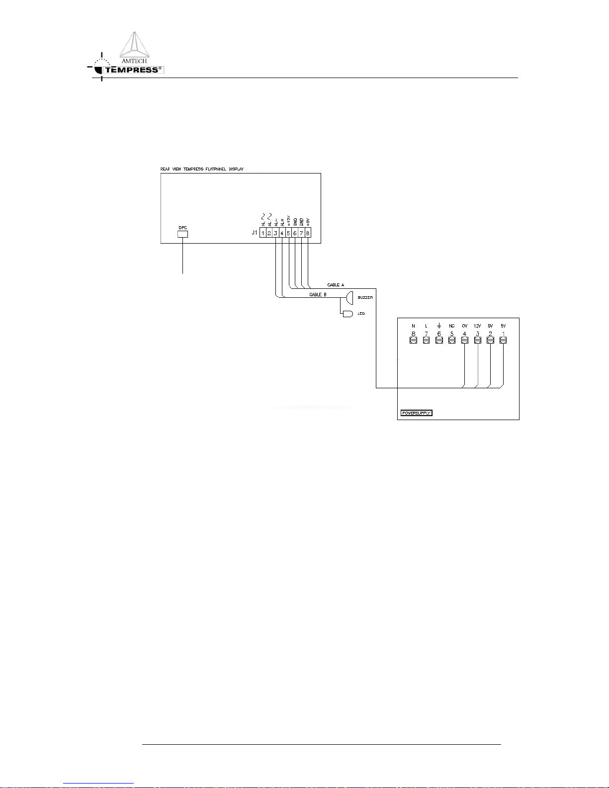
9. Secure the touchscreen with the screws. It is now ready for starting.
10. Turn the tube switch on. The Main Menu should appear after about 10 seconds.
Figure 3-1 Location of Connectors
TOUCHSCREEN REFERENCE MANUAL
3-2
Page 11
SCREEN HIERARCHY
TOUCHSCREEN REFERENCE MANUAL
4-1
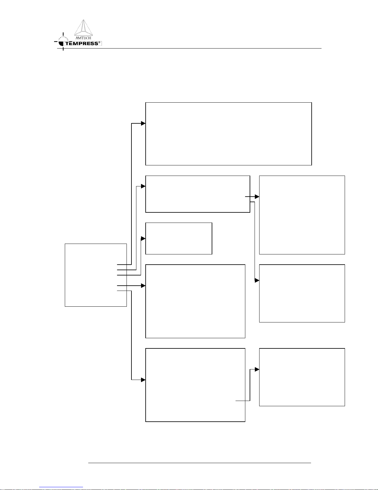
4.Screen Hierarchy
RATURE MENU
MAIN MENU
1. System Control
2. Certifications
3. Process Recipes
4. Tube Control
5. Monitor
MONITOR
TEMPE
1.
Temperature Status
2. Normal Recipe Status
3. Profile Recipe Status
4. Paddle Correction and
Parameters
DTC CERTIFICATION
MENU
1.
Tube Configuration
2. Normal Temperature Table
3. Profile Temperature Table
4. Paddle TC Calibration Table
5. PID Parameter Table
MONITOR MENU
1. Main Detail Status
2. Alarm Status
3. Digital Output/Input
4. DPC Lot ID Status
5. Process Recipe Status
6. Temperature Status
7. Graphic Process Status
PROCESS CONTROL MENU
1. Graphic Process Control
2. Start/Stop Process Recipe
3. Abort Process Recipe
4. Clear Alarm
5. Variable Process Command
6. Select a Process Recipe
7. Assign Control Zones
8. Edit Lot Id
DPC CERTIFICATION MENU
1. Tube Id and Tube Name
2. Tube Configuration
3. Analog Output
4. Analog Input
5. Digital Output
6. Digital Input
7. Messages
8. Graphic System Layout
9. Servo Driver Parameter (*)
EDIT MENU
Edit a Process Recipe
T
UBE CERTIFICATION MENU
1. Process Controller Certification
2. Temperature Controller Certifications
SYSTEM CONTROL MENU
1. Access Control
2. Access: Start on another recipe STEP (Status = YES/NO)
3. Buzzer (Status = ON/OFF)
4. Set Date and Time
5 Tube Control Mode
Figure 4-1 Screen Hierarchy
Page 12

DATA INPUT
5.Data Input
Once the desired screen has been obtained, numeric or text entries can be made by the
alphanumeric keys displayed at the bottom of the screen. If only numeric entries are required,
Any mistake made before pressing <RETURN> can be corrected by using the right and left
arrows to locate the cursor over the wrong digit and correct it.
keyboard is displayed in the bottom half of the
The different ke
9> , : , . , - , / , < , >.
<SPACE> This is a space bar and produces a gap in text input.
N>
ESCA E>, splayed menu. If this key
<INS> sert key. This causes subsequently entered data to be stored at
DEL> This is the delete key. This causes the character at the position of the cursor
the left.
< > < > These cursor control keys will move the cursor from field to field.
< > < > These cursor control keys will move the cursor from section to section.
< > Move the cursor one row up, in the same column.
< > Move the cursor one column left, in the same row.
< > Move the cursor one column right, in the same row.
< >
- -> and <- - to be moved to any position in the current field,
CAP> This is a shift-lock key and will cause all subsequent data to be input in
lower case. Press a second time to revert to upper case.
one line of digits is displayed. Enter data by selecting the required sequence of digits,
followed by <RETURN>.
5.1 Using the qwerty keyboard
On requiring text input, a QWERTY style
screen. This allows normal alphanumeric input and also provides certain editing functions.
ys are summarized below:
<A-Z>, <0- Used for alphanumeric input. Also provided are *
When pressed, these keys are reproduced on the screen.
<RETUR Pressing this key will cause the input data to be stored.
< P Pressing this key will return the user to the Last di
<ESC> is pressed before the <RETURN> key, changes made since the
<RETURN> key was last used will not be stored.
This is the in
the position of the cursor, with any data already displayed moving one space
to the right.
<
to be deleted, with any data already displayed moving one space to
Move the cursor one row down, in the same column.
They enable the cursor
without affecting the displayed data. They will move the cursor from
character to character.
<
TOUCHSCREEN REFERENCE MANUAL
5-1
Page 13
OPERATION MENU’S
6. Operation menu’s
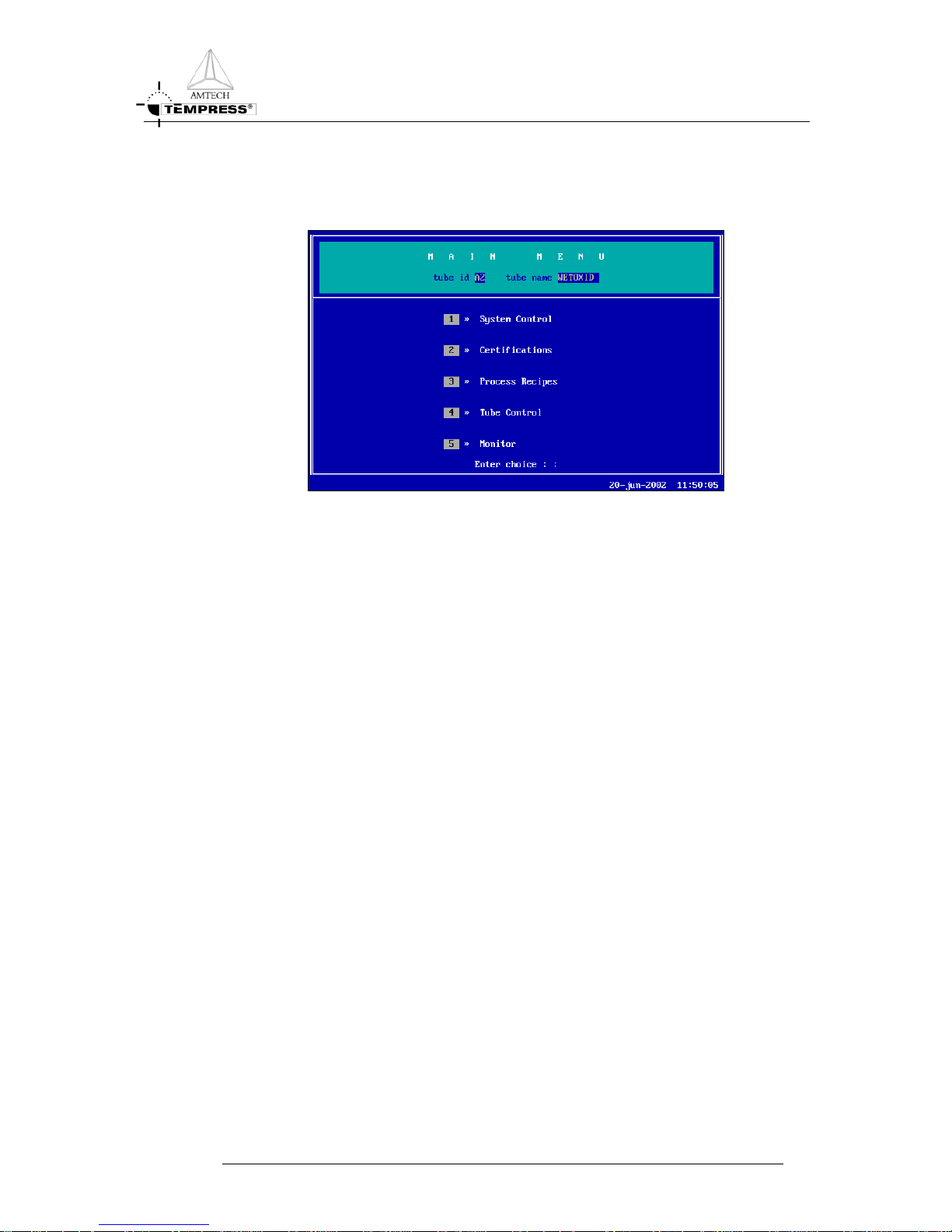
Figure 6-1 Main Menu
This is the first screen after power-on. The Main Menu has a title bar containing the menu
name, the tube identification number and the tube name. The center of the screen contains
five menus, and the bottom line gives the date and time and allows at any moment alarm
messages to be displayed.
The menus are ordered in a security hierarchy, being the top menu the highest security level
and the bottom menu the lowest security level.
1. System Control
There are five security levels to the touchscreen. The access rights can be restricted via this
System Control Menu. At time of delivery the touchscreen is set unrestricted.
The access levels for the system are given below:
1. SYSTEM CONTROL SYSTEM MASTER
2. CERTIFICATIONS SYSTEM ENGINEER
3. PROCESS RECIPES PROCESS ENGINEER
4. TUBE CONTROL OPERATOR
5. MONITOR EVERYONE
TOUCHSCREEN REFERENCE MANUAL
6-1
Page 14

OPERATION MENU’S
2. Certifications
The Certifications Menu describes the hardware to the DPC and DTC. This menu is split up
in two parts, one for the DPC and one for the DTC. It is vital that the information stored in
those submenus matches the actual hardware.
3. Process Recipes
Process recipes are programmed and modified in this menu. A recipe editor selection screen
allows a new recipe to be made or an existing one to be modified. Two types of recipes are
available: Normal and Abort. The Normal recipes are used for regular processing. The Abort
recipes can be used to automatically handle possible dangerous situations.
4. Tube Control
The Tube Control Menu is used to start, stop or abort a process recipe, clear possible alarms,
set variable commands and assign temperature control zones. It is the most often used menu
while working with a furnace.
5. Tube Control
This freely accessible menu allows a quick glance on the current situation in the tube. The
current status of the alarms, recipes, digital input/outputs, paddle parameters or to give a
graphic display of the current system. It is not possible to make changes using this selection.
TOUCHSCREEN REFERENCE MANUAL
6-2
Page 15
OPERATION MENU’S
6.1 System controller
Entering the System Control Menu requires a username and a password.
Figure 6-2 System Control Access Screen
It is recommended to set these settings first. Once the other access rights have been changed,
the System will not allow access to a second level menu without a name and password.
Once the NAME and PASSWORD are given, the following screen with the “SYSTEM
CONTROL MENU” will appear:
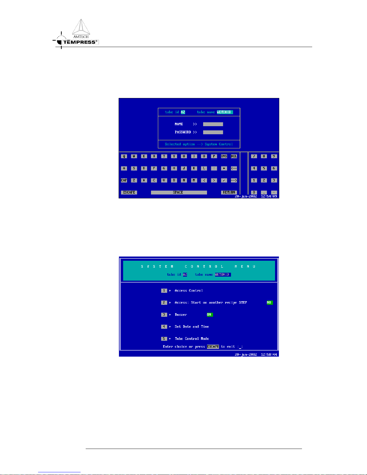
Figure 6-3 System Control Menu
TOUCHSCREEN REFERENCE MANUAL
6-3
Page 16
OPERATION MENU’S
6.1.1
Access control
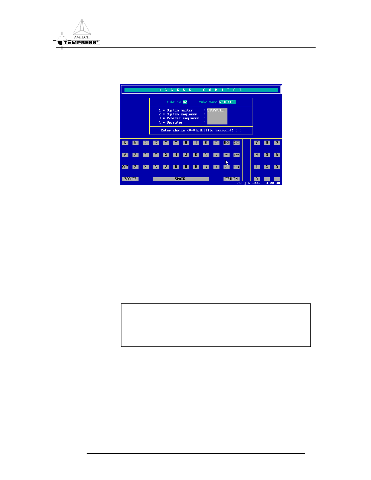
Figure 6-4 Access Control
Access Control gives the opportunity to make a distinction in the user access rights. To edit a
username and password, press the corresponding number (1 to 4). The username may consist
of ten characters, the password only five.
Press <V> to make all the passwords visible.
1. System Master : To change the name of the highest level of access.
2. System Engineer : To change the name of the second level of access.
3. Process Engineer : To change the name of the third level of access.
4. Operator : To change the name of the fourth level of access.
To leave “Access Control” menu press <ESCAPE>.
NOTE
If the Sysmaster username and password have been changed
confirmation is required when exiting the Access Control Menu.
Do not forget Sysmaster settings!!
TOUCHSCREEN REFERENCE MANUAL
6-4
Page 17
OPERATION MENU’S
6.1.2
Start on another recipe STEP (status= YES / NO)
To change access/status of ‘starting on another recipe step’ in YES or NO. To allow jumping
to another step in a running process recipe set status to ON. Disabling this feature is done by
selecting this menu item again.
YES To make it possible to jump to another step in the recipe.
NO It is not allowed to jump to another recipe step.
CAUTION Jumping to a wrong process step may cause serious danger.
6.1.3 Buzzer (status= ON / OFF)
The buzzer gives a continuous audible signal to alert users for alarms and an intermittent
audible signal for operator warnings.
The buzzer can be completely switched off with this menu item. Alarms will still be visible in
the bottom line of the touchscreen.
ON Every time an alarm appears on the TOUCHSCREEN, the buzzer will give
a sound. By touching the screen the alarm will stop.
OFF An alarm will only appear on the TOUCHSCREEN. The buzzer will not
give any sound during the whole process/recipe.
6.1.4
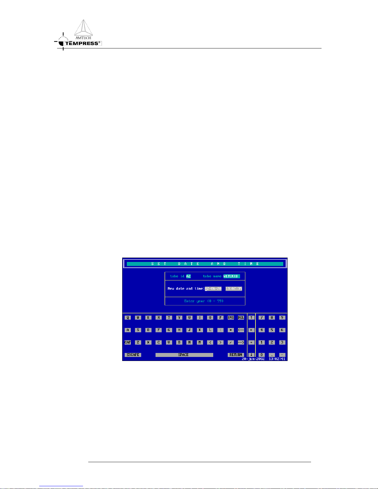
Set Date and Time
Figure 6-5 Set Date and Time
Enter the correct values; use the numeric keys on the right. Press <RETURN> to confirm or
<ESCAPE> to discard the changes and return to the “System Control Menu”.
Press <ESCAPE> to exit the menu until the Main Menu is displayed. Do not forget the
System Master name and password, because entry to the access control menu is no longer
possible without them.
TOUCHSCREEN REFERENCE MANUAL
6-5
Page 18

OPERATION MENU’S
6.1.5
Tube control mode
Tube Control takes place by Touchscreen and TSC-II. Tube Control Mode Menu allows to
define which one of the user interfaces is allowed to control the tube. This is to provide
unauthorized or unwanted recipe selection, or starting and stopping a recipe.
It can be important to disable one (or both) controller interface(s) to prevent any dangerous
situation, like starting a recipe from TSC-II (remote control) at the same time the
maintenance engineer is working on the system.
Figure 6-6 Tube Control Mode Menu
6.1.5.1 Start Recipe Control
Start Recipe Control mode allows 4 levels of authority concerning the tube control by TSC-II
or Touch Screen:
REMOTE (TSC)
Tube control is only possible by using the TSC-II server. In this configuration the Touch
Screen is blocked.
NORMAL (Local + Remote)
Tube control is possible with the Touch Screen as well as the TSC-II server.
DISABLED
Tube control is not possible at all. Not by the Touch Screen and not by the TSC-II.
LOCAL (Touch Screen)
Tube control is only possible by using the Touch screen. In this configuration the TSC-II
server is blocked.
NOTE
Due to safety reasons, aborting a recipe is always possible via the
touch screen or the TSC2.
TOUCHSCREEN REFERENCE MANUAL
6-6
Page 19

OPERATION MENU’S
6.1.5.2 Select Recipe Control
Select Recipe Control mode allows 4 different levels of authority concerning recipe selection:
REMOTE (TSC)
Recipe selection is only possible via the TSC-II.
NORMAL (Local + Remote)
Recipe selection is possible via the TSC-II as well as the Touch Screen.
DISABLED
Recipe selection via the TSC-II as well as the Touch Screen is not possible.
LOCAL (Touch Screen)
Recipe selection is only possible via the Touch Screen.
6.1.5.3 Normal / Maintenance Mode
This mode has two options:
NORMAL
Tube control and recipe selection is possible according the configuration of authority of
“Start and Select recipe control”.
MAINTENANCE
Both, Touch Screen and TSC-II are blocked. Only aborting a running process recipe is
possible via TSC_II as well as touch screen.
TOUCHSCREEN REFERENCE MANUAL
6-7
Page 20

OPERATION MENU’S
6.2 Certifications
Figure 6-7 Tube Certification Menu
‘Certifications’ in the Main Menu gives access to the submenu ‘Tube Certification Menu’.
This submenu gives access to the DPC and the DTC certifications.
1. Process Controller Certifications
To change the certifications of the Digital Process Controller (DPC).
2. Temperature Controller Certifications
To change the certifications of the Digital Temperature Controller (DTC).
TOUCHSCREEN REFERENCE MANUAL
6-8
Page 21

OPERATION MENU’S
6.2.1
Process Controller Certifications
Figure 6-8 DPC Certification Menu
1. Tube Id and Tube Name: To change the Id or name of the tube.
2. Tube Configuration: To change the number of process recipes, pressure
control or boat parameters.
3. Analog Outputs: To change the parameters of any of the analog
outputs or interlocks between analog and digital
outputs.
4. Analog Inputs: To change the parameters of the analog inputs.
5. Digital Outputs: To change the parameters of the digital outputs.
6. Digital Inputs: To change the parameters of any of the digital
inputs.
7. Messages: To change any of the 16 available messages in the
system.
8. Graphic System Layout: To make alterations to the graphic display.
TOUCHSCREEN REFERENCE MANUAL
6-9
Page 22

OPERATION MENU’S
6.2.1.1 Tube Id and Name
Figure 6-9 Tube Id and Tube Name
This screen enables the user to change the Id and the name of the tube.
Enter the new Id, with a maximum of two characters, followed by <RETURN>. The first
character must be a letter of the alphabet in the range A to Z. The second character must be
a number in the range 0 to 9.
6.2.1.2 Tube Configuration
Figure 6-10 Tube Configuration DPC
This screen enables the selection of the number of recipes, boat parameters and the pressure
control parameters. The new value will be stored by pressing <RETURN>. The current
value can be kept by confirming with the <RETURN> key. The information in brackets
show the range of the possible values for each parameter.
Process Recipes The total number of process recipes can be change between 8 (8x
1500 bytes) or 16 (16x750 bytes).
TOUCHSCREEN REFERENCE MANUAL
6-10
Page 23

OPERATION MENU’S
Boat Loader When it is installed, this field shows the minimum and maximum
position of the boat. (The number of pulses per mm. is only
applicable to old step motors. The current servo motors do not use
this parameter).
External Pressure: YES: Nothing can be edited. Pressure will be controlled externally.
NO: The range may be edited (with a maximum of five sub ranges).
After editing the ranges, the PID can be entered.
To correct a mistake the cursor can be positioned over the incorrect value, using either the
<RETURN> key (to move down) or the <
> key (to move up). Enter the correct value
and confirm with the <RETURN> key. To move the cursor to the right or left, without
altering any digits, use <
> and < >.
Press <ESC> to return to the DPC Certification Menu.
6.2.1.3 Analog Outputs
Figure 6-11 Analog Output
This screen displays the current settings of the analog outputs. To define an analog output,
select the number.
Give for each output the name (mnemonics, maximum eight characters), interlock type,
upstream or downstream valve, the minimum and maximum range value, the multiplication
factor and its unit. Confirm input data by pressing <RETURN>.
If there are more than four analog outputs, press <N> to go to the next four combinations.
TOUCHSCREEN REFERENCE MANUAL
6-11
Page 24

OPERATION MENU’S
6.2.1.4 Analog Inputs
Figure 6-12 Analog Inputs
This submenu defines the settings for the analog inputs. To define an analog input first select
its number.
Give for each input the name (mnemonics, maximum eight characters), the minimum and
maximum range value and its unit. Confirm input by pressing <RETURN>. The possible
input selection is shown on the line above the keyboard.
When all the alterations have been made, press <ESCAPE> to return to the DPC
Certification Menu.
6.2.1.5 Digital Outputs
Figure 6-13 Digital Outputs
This submenu defines the digital outputs. The output can be edited by entering its number,
followed by <RETURN>. When the name is set, confirm with the <RETURN> key. When
all the changes are performed, press <ESCAPE> to return to the DPC Certification Menu.
If there are more than sixteen digital outputs, press <N> to go to the next sixteen
combinations.
TOUCHSCREEN REFERENCE MANUAL
6-12
Page 25

OPERATION MENU’S
6.2.1.6 Digital Inputs
Figure 6-14 Digital Inputs
This submenu defines the Digital Inputs.
The input can be edited by entering its number, followed by <RETURN>. When the name
is set, confirm with the <RETURN> key. When all the changes are performed, press
<ESCAPE> to return to the DPC Certification Menu.
If there are more than sixteen digital inputs, press <N> to display the next sixteen
combinations.
6.2.1.7 Messages
Figure 6-15 Messages
This screen displays the current messages and the message number to which they are
assigned. There are initially eight of the maximum sixteen messages assigned, although any
may be changed.
A mnemonic can be changed by using the cursor control keys and entering another or a new
mnemonic. When all messages have been edited, press <ESCAPE> to return to the DPC
Certification Menu.
TOUCHSCREEN REFERENCE MANUAL
6-13
Page 26

OPERATION MENU’S
Use messages as mnemonics in your recipe. During the process these messages give an idea
of the progress of the process.
6.2.1.8 Graphic System Layout
Figure 6-16 Graphic System Layout
There are two options, Graphics-1 and Graphics-2. ‘Graphics–1’ gives the possibility to
design a graphic display. It is used to design the tube type, the pressure valves, the pump
valve, the vacuum valves, the top tube-line valves and the bubbler. It is used in combination
with the screen ‘Graphics–2’. This one is used to draw the other valves and meters used in
the system. Where ‘Graphics–1’ ends, ‘Graphics–2’ will continue.
After the screen has been activated (ON), up to four graphics can be designed and seen.
May be not all elements are present on your system. If this happens, unwanted elements can
be omitted.
TOUCHSCREEN REFERENCE MANUAL
6-14
Page 27

OPERATION MENU’S
6.2.2
Temperature Controller Certifications
Figure 6-17 DTC Certification Menu
This menu is used to configure the DTC parameters. It is VITAL that the parameters match
the actual hardware. Failure to do so leads to serious danger. It is not possible to choose
another tube from this menu. The following options are available from this menu:
1. Tube Configuration:
The type of spike or paddle thermocouple, operating temperature range, maximum heat up
rate and maximum profile deviation can be modified here.
2. Normal Temperature Table:
The process temperatures are predefined in the Normal Temperature Table. A maximum of
sixteen individual temperature recipes are available.
3. Profile Temperature Table:
The profiling temperatures are predefined in the Profile Temperature Table. A maximum of
sixteen individual profile temperatures are available.
4. Paddle TC Calibration Table:
Correction temperatures for a calibrated paddle (=profile) thermocouple can be stored in this
table.
5. PID Parameter Table:
The proportional, integral or derivative parameters of the spike or paddle thermocouples for
any of the temperature ranges can be modified in this table. USE WITH CARE!
TOUCHSCREEN REFERENCE MANUAL
6-15
Page 28

OPERATION MENU’S
6. Maximum Spike Correction Table:
The maximum spike correction table is used to prevent large overshoot in special situation.
6.2.2.1 Tube Configuration
Figure 6-18 Tube Configuration
The Tube Configuration Menu is used to set the type of thermocouples on the furnace, the
maximum heat up rate and the maximum profile deviation. The cursor position in
highlighted and the context sensitive information is displayed on line “Enter thermocouple
type (0-4)”. Confirming the selection with <RETURN> will move the cursor to the next
item automatically.
If an error is made the cursor can be moved back to a value using the < > key.
The <
> and < > allow the cursor to be moved to the left or right within the current
parameter, without altering any digit.
Spike Thermocouple Type:
To select the required thermocouple type, press the corresponding number (the possibilities
are shown on the upper right corner of the screen), followed by <RETURN>. If no changes
are required, press <RETURN> only. The cursor will automatically move to the paddle
thermocouple entry, which can be changed in the same way.
Operating Temperature Range:
The operating temperature range can be changed next and it must match the thermocouple
type. First enter the minimum temperature, followed by <RETURN>. Then enter the
maximum temperature.
TOUCHSCREEN REFERENCE MANUAL
6-16
Page 29

OPERATION MENU’S
Maximum Heat Up:
The maximum heat up rate is a software limitation on the maximum ramp-up speed for each
temperature range. The maximum heat up rate can be anything between 0.0 (= no limitation)
and 25.5ºC/min. (controlled).
Maximum Profile Deviation:
The maximum profile deviation is a limit used for profiling the tube. When profiling, the
temperature must be at its setpoint within this limit for 15 minutes in all the zones. The
temperature must remain at its setpoint within this limit to allow the profile table to be
updated.
TOUCHSCREEN REFERENCE MANUAL
6-17
Page 30

OPERATION MENU’S
6.2.2.2 Normal Temperature Table
Figure 6-19 Normal Temperature Table
The Normal Temperature Table consists of 16 positions (0-15) for process temperature
recipes. These process temperature recipes can be selected based on recipe number. Every
process temperature recipe contains the following parameters:
Recipe number:
The recipe number is the main source of recipe selection. To select a recipe, position the
cursor over the recipe number and enter the number of the new recipe in the range 0 to 15 or
press <RC+> or <RC-> to scroll up and down. When the desired recipe number has been
selected press <RETURN> to fill in its parameters.
Temperature Setpoint:
Enter the Temperature Setpoint for each zone. Each entry must be in the range 0.0 (Tmin.)
to 1400.0 (Tmax.)
0
C, as defined in the DTC configuration based on the type of
thermocouple, see Figure 6-19.
Slope:
Te slope is the temperature rise in C/min of the Setpoint. The actual temperature will rise
with equal rate after some delay. Each entry can be in the range 0,0 to 99.0 C/min. the actual
temperature rise is hardware restricted (due to power transformer limitation) and is software
limited (see DTC configuration in Figure 6-18) to extent the heating element lifetime.
TOUCHSCREEN REFERENCE MANUAL
6-18
Page 31

OPERATION MENU’S
High/Low limits:
The high and low limits are used to allow some temperature deviation around the setpoint. If
the actual temperature falls outside these limits a temperature alarm is generated. The limits
must be in the range 0.0 to 25.5 C where 0.0 means NO alarm limit set.
GAIN:
The gain is a amplification factor in the PID temperature control Loop and can be increased
if a particular temperature zone does not reach its setpoint. Default setting is 100%, the range
is 0% (means no power output) to 255% (maximum amplification).
Control:
The control section of the normal (process) temperature table defines the type of
thermocouple that is used as input signal (spike or paddle) to the PID temperature control
loop.
In addition, the behaviour of the different temperature control zones can be modified.
Default the temperature zones are independently controlled to provide the fastest result. If so
desired the center zone can be used as master and the outer zones will follow as slave when
the type of control is set to master/slave.
To change the type of control on the furnace, the <CONTROL> key must be pressed, the
cursor will move to the first input behind “CONTROL”. This will enable the spike (press
<S>) or paddle (press <P>) thermocouples to be selected for control. Selecting one of these
will allow independent control (press <I>), or master/slave control (press <M>) to be
selected. The control can be left unchanged by pressing <ESC> or the cursor control key
down <
>.
6.2.2.3 Profile Temperature Table
Figure 6-20 Profile Temperature Table
The Profile temperature table is used to increase temperature accuracy for process runs.
TOUCHSCREEN REFERENCE MANUAL
6-19
Page 32

OPERATION MENU’S
Four profile temperature tables are available (A-D) to accommodate different process
environments. Typically only one table is used, occasionally two (such as dry and wet
environment in a steam oxidation capable table).
The paddle setpoint entries will be the same to all four tables and must be entered in
ASCENDING order. Failure to do so will generate an error message when exiting the profile
temperature table menu. A particular profile temperature table can be selected by pressing A,
B, C, D. the profile temperature table exists of four columns. The first (small) column
contains the profile temperature recipe number (0-15). The second column contains the
paddle setpoints for each temperature zone. Zones 4 and 5 if applicable can be made visible
by pressing <NEXT>.
The third and fourth columns contain the corresponding spike values and required power
output to reach the paddle setpoint is column 2. These values are entered automatically when
the automatic profiling procedure is performed.
<I(nsert)> This enables a profile temperature recipe to be inserted into the table. All
the other lines in the table are moved down one line.
<E(rase)> This will delete the profile temperature recipe at the cursor position. All the
other lines in the table are moved up one line.
6.2.2.4 Paddle TC Calibration Table
Figure 6-21 Paddle TC Calibration Table
The paddle calibration table can be used to further improve temperature accuracy. It is only
useful when a certified calibrated paddle thermocouple is available. Regular recalibration of
this paddle thermocouple is required. (At least every 6 months, severe temperature cycles
and/or high intensity use may require even shorter recalibration interval.)
The certified calibrated paddle thermocouple comes with a calibration table that must be
entered here to allow the DTC to compensate for the calibrated paddle thermocouple
properties. Up to 6 calibrated temperatures can be stored. They must be in ASCENDING
order. Failure to do so will generate an error manage when exiting the paddle calibration
menu.
TOUCHSCREEN REFERENCE MANUAL
6-20
Page 33

OPERATION MENU’S
NOTE
If a not calibrated paddle thermocouple is used the calibrated values of
each zone must be made equal to the calibration temperature.
<INSERT> This enables a profile temperature recipe to be inserted into the table. All
the other lines in the table are moved down one line.
<ERASE> This will delete the profile temperature recipe at the cursor position. All the
other lines in the table are moved up one line.
The line above the cursor movement keys has a brief description of the possible input values,
the range and its unit.
6.2.2.5 PID Parameter Table
Figure 6-22 PID Parameter Table
The PID parameter table defines the proportional, integral, derivative and gain parameters
for the spike TC’s and the integral and derivative parameter for the paddle TC. The default
values have been optimised to accommodate 98% of all hardware configurations. The values
need only be modified if temperature problems such as overshoot and/or extremely long
stabilization times are experienced. A particular example is the use of a heating element at
temperatures well below its specified range (such as an A1 heating element operating at
425C where a low temperature element should have been used).
TOUCHSCREEN REFERENCE MANUAL
6-21
Page 34

OPERATION MENU’S
6.2.2.6 Maximum Spike Correction Table
Figure 6-23 Maximum Spike Correction Table
The maximum spike correction table is used to prevent excess temperature overshoot in the
particular situation of Paddle Control and Boat Out.
Due to cold cleanroom air entering the process tube when the boat is out the door zones
measured by the paddle thermocouple will cool down. Without the maximum spike
correction table filled the DTC would respond with power increase for the affected zones.
When the boat is moved in the latent heat provided by this DTC action results is a large
temperature overshoot and subsequent longer stabilization times. With the maximum spike
correction table filled (default 6.0 C) the DTC is allowed only the stored value (6.0 C)
temperature rise on the spike TC, thereby limiting the latent heat and reducing temperature
overshoot and stabilization times upon door closure.
6.3 Process Recipes
Figure 6-24 Edit A Process Recipe
The creation and/or editing of a process recipe use a specially designed editor that is fully
menu-controlled. This chapter outlines the use of each mode and explains the major screens
TOUCHSCREEN REFERENCE MANUAL
6-22
Page 35

OPERATION MENU’S
used in editing a recipe. Appendix A gives a detailed description of all the commands that can
be entered.
Selecting the menu <3> Process Recipes on the Main Menu gives the screen: Edit A Process
Recipe.
The current process recipe number and name are presented at the top, including its
numbering status. Two columns for normal process recipes are available on the left, giving 16
process recipe positions (with a maximum length of 750 bytes) One column on the right
shows 8 positions for abort recipes. Abort recipes allow the automatic return to a safe
situation if the “Abort” command is executed.
To select a recipe, select <NORMAL> or <ABORT> recipe, followed by its number.
Choose “0" to enter a new recipe.
Note: The current recipe has been preselected for editing. If you want to edit the current
recipe, just press <RETURN>.
To return to the Main Menu, press <ESCAPE>.
6.3.1
Edit a Process Recipe
Figure 6-25 Recipe Editor
This is the recipe editor. The top of the screen shows the Tube Id, the Tube Name, whether
it is a normal or abort recipe, its name and number of bytes.
Once a mode has been entered (Append, Change, Insert, Delete, Store), the system prompts
the entry of the number corresponding to the required command. The available commands
for a step are displayed at the bottom of the screen.
Exit mode without storing, by pressing <ESCAPE>, the system will prompt:
“All recipe changes will be LOST if you EXIT now”. Enter ‘STORE’ or ‘EXIT’
(‘ESCAPE’=continue editing)”
When an existing recipe has been changed, press <5> (Store). Press <NAME>, to change
the name or <RETURN> to go on. Press <YES> to store, or <NO> to cancel the recipe.
TOUCHSCREEN REFERENCE MANUAL
6-23
Page 36

OPERATION MENU’S
Editing modes
1=Append The Append mode allows a new command to be added at the end of the
process recipe. The editor asks: “Enter command to append (Y/N for New
Process Step). Press “Y” to create a new step, or “N” to insert the step into
the current one. A display of the possible commands is given, each having a
corresponding number (see Appendix A). To enter a command, enter its
associated number. Enter the parameters or a specific type of the command.
When the instruction is completed, it will be displayed on the screen and
the user is given the opportunity to leave the append mode (press
<ESCAPE>).
2=Change The ”Change” mode allows an existing command to be modified. “Enter
LINE number to change”. When the desired line number has been entered,
the command is displayed with all its possible parameters. Modify the
desired parameter; press <RETURN> to skip the parameter. When the
instruction is completed, it will be displayed on the screen. Press
<ESCAPE> to leave “Change Mode” and return to the recipe or change
another command.
3=Insert The “Insert” mode allows a new command to be inserted above a selected
line number. All lines below the specified line are moved down to
accommodate the new lines. Press <3> and “Enter LINE number to
insert”.
4=Delete The “Delete mode” allows a command line or a complete process step to be
deleted. Press <4> followed by the line number, which have to be deleted.
Once the line number has been entered, the line is removed form the recipe
and all other lines move up one line. The step number in any branch
instruction in the recipe is automatically recalculated. Enter new line number
to delete its so desired or press <ESCAPE> to leave “Delete Mode”.
5=Store The “Store mode” allows the modified process recipe to be stored in a
particular process recipe location identified by its recipe number. Selecting
this option (press <5>) will invoke the recipe storing procedure. Enter the
recipe number where the recipe has to be stored. The recipe name can be
modified by selecting “Name” If the editor screen is exited by pressing
<ESCAPE> without prior storage of the process recipe the editor will
automatically give the option of storing the recipe anyway selecting “Store”
to store the modified recipe or select “Exit” to leave the editor without
applying changes. When the message “Process Recipe Stored” is displayed
the recipe is correctly stored under the selected Id.
The same command programming is available as with “Append mode” once the new line has
been selected. Press <ESCAPE> to leave “Insert” mode and return to the recipe.
TOUCHSCREEN REFERENCE MANUAL
6-24
Page 37

OPERATION MENU’S
NOTE
If a new step is inserted any branch instruction in the recipe is
automatically recalculated.
Paging modes
The paging modes First, Next, Previous, Last and Step allow navigation through a process
recipe.
6 FIRST Moves the cursor to the first line of the process recipe.
7 NEXT Scrolls one screen down.
8 PREVIOUS Scrolls one screen up
9 LAST Moves the cursor to the last line of the process recipe
0 STEP Allows the user to enter the step number to which the cursor needs to move
to directly.
6.4 Tube Control
Figure 6-26 Process Control Menu
The Process Control Menu provides the main items to run a process recipe, including
process recipe selection, start, stop and abort and quick modification of save (preselected)
process parameters.
1. Graphic Process Control
The Graphic Process Control displays a graphical setup of the tube and shows the current
status including temperature, pressure (if available), gasflows, boat position and process
recipe name, step and remaining time.
TOUCHSCREEN REFERENCE MANUAL
6-25
Page 38

OPERATION MENU’S
From this screen it is possible to start stop the current process recipe, abort that recipe or
return to the Process Control Menu.
2. Start/Stop Process Recipe
To start a new process recipe or allow a current recipe to be continued when it has been
paused can be done with this instruction. These include starting from “step 0” or continue at
a “Wait for Operator” command.
Optionally a direct selection of a specific process step (also known as jumping to another
step) can be performed here as well.
NOTE
Jumping to another step is only possible with a paused process recipe.
TOUCHSCREEN REFERENCE MANUAL
6-26
Page 39

OPERATION MENU’S
3. Abort Process Recipe
The abort instruction can be used to kill a running process recipe in case of emergencies.
Automatic abort commands can be implemented in the process recipe to handle out of
buzzer or sensor signal failure situation. A manual abort command can be issued in this menu
only.
Any abort command that is executed will reset the process recipe to “step 0” unless proper
abort recipes are used. See chapter Process Recipe for further details.
4. Clear Alarms
The clear alarm instruction will reset the current alarm list. The previous alarm list is also
reset when a process recipe is started from “step 0”.
5. Variable process Command
The variable process command is a list of preselected process parameters that have been
assigned to be variable. This list allows rapid change of setpoints without the use of the
“Recipe Editor”.
6. Select a Process Recipe
A list of all available process recipes allows the operator to select the desired recipe.
NOTE
Another process recipe can only be selected if the current recipe is in “step
0”.
7. Assign Control Zones to Paddle Inputs
Assigning control zones to paddle inputs allows internal (paddle) thermocouple signals to be
used in the DTC temperature control loop.
8. Edit Lot Id
A lot Id (a name) can be given here. Only its name, type, number of wafers and the slot
number can be entered. A batch of wafers often comes with Lot ID. Its name and content
(filler, test and/or process type) plus amount of each wafer type and its Lot number can be
stored.
TOUCHSCREEN REFERENCE MANUAL
6-27
Page 40

OPERATION MENU’S
6.4.1
Graphic Process Control
Figure 6-27 Graphic Process Control
The Graphic Process Control is a graphical interface to the tube control. The screen contains
three main divisions, the process recipe status in the top field, the tube status in the large
center field and the control buttons on the left.
Any alarm messages will be displayed in the bottom line
The process recipe field shows
• The tube Id and name
• The recipe Id and name
• The message for the current step
• The action for which the controller is waiting
• The process time
• The step number and time
The tube status field gives a graphical overview of the temperature (both spike (eternal) and
paddle (internal) thermocouple signals), boat position, MFC and valve setting and pressure (if
applicable).
TOUCHSCREEN REFERENCE MANUAL
6-28
Page 41

OPERATION MENU’S
TOUCHSCREEN REFERENCE MANUAL
The following symbols are used
Open Valve
Flow Meter
Closed valve
Pump
Fine Metering Valve
(FM)
Tube
Mass Flow
Controller
Orifice
Baratron
Up to four graphical screens can be setup to fully match the tube hardware. Each screen can
be accessed by using the <NEXT> button in the bottom right corner.
6-29
Page 42

OPERATION MENU’S
6.4.2
Start/Stop Process Recipe
Figure 6-28 Start/Stop Process Recipe
The <Start> command is used to start a process recipe, that is to go from Step “0” to step
“1”. Additionally, <Start> will be required to continue a process recipe if it has been paused
by the Stop command and if the system is “Waiting for operator”.
The <Stop> command is used to stop the timer in a particular process step. The current
process status is presented in the center screen. It includes process recipe id and name,
optional variable time, the current process step and its running status.
An optional <Jump> command can only be issued if the process recipe is stopped. It is not
possible to jump to another process step if the process recipe is still running.
NOTE
Jumping to another process step may cause dangerous situations. Verify
the settings in the jumped to step before using this command.
TOUCHSCREEN REFERENCE MANUAL
6-30
Page 43

OPERATION MENU’S
6.4.3
Abort Process Recipe
Figure 6-29 Abort Process Recipe
The abort command is a powerful instruction that will bring the tube in a safe state. Abort
instruction can be implemented in the process recipe to automatically handle undesired
situation such as pressure failure, gas flow problems and temperature related issued.
Additionally a manual operator command can be accessed at this menu.
If a process recipe is aborted (either automatically or by operator) the process controller
(DPC) will return the process recipe to step “0” immediately. Therefore it is of vital
importance that step “0”has been programmed to create a safe situation.
In the event that step “0” can not be used to create safe conditions (which is common in a
production environment where a minimum of operator handling is required) the use of abort
recipes is obligatory.
Then, any abort command will not have the process recipe to be returned to step “0”
immediately but the activated abort recipe will be performed. When the abort recipe has
reached the END command only then the (aborted) process recipe will be returned to step
“0”.
NOTE
Operator initiated aborts may be used if an operator detects a
dangerous situation in the archive that is not handled automatically.
This includes the erroneous starting of the wrong process recipe.
An abort alarm will be generated with indicated time and abort
condition each time an abort command is issued.
TOUCHSCREEN REFERENCE MANUAL
6-31
Page 44

OPERATION MENU’S
6.4.4
Clear Alarms
Figure 6-30 Clear Process Alarms
Alarm messages are generated automatically and indicate the type of alarm and location (for
example Digital Input number 1 (N
2
pressure)). Solving the cause of the alarm condition
automatically removes the alarm from the current alarm list (it will be stead in the process
alarm list for review). This is however not valid for the Abort Alarm. The Abort Alarm can
only be removed by the ”Clear Alarm” command accessed in this menu.
<YES> to clear the alarm list.
<NO> to return to the Process Control menu.
<ESCAPE> to go back to the Process Control Menu.
6.4.5
Variable Process Command
Figure 6-31 Variable Process Commands
TOUCHSCREEN REFERENCE MANUAL
6-32
Page 45

OPERATION MENU’S
Press <ESCAPE> to go back to the Process Control Menu. If any changes have been made,
the new values will be stored and the following message will appear: “Process variable
commands are stored”.
The Variable Process Command is a special instruction used to quickly modify predefined
commands from the process recipe, without the need to use the recipe editor. Typically,
commands such as gasflow (and pressure) and process time settings are assigned to be
variable. Only those assigned commands will be presented in the list of Variable Commands
if that menu is selected.
Press <ESCAPE> to store the new settings and return to the “Process Control Menu”. A
brief 3-second message “Process variable commands are stored” will be shown to conform
the new settings.
6.4.6
Select a Process Recipe
Figure 6-32 Select a Process Recipe
The selection of a new process recipe requires the current process recipe to be in step “0”.
A list of all available process recipes is prevented if the current process recipe is indeed in
step “0”. To change the selection of the recipe, enter the recipe number followed by
<RETURN>. Confirm with <YES> or press <NO> or <ESCAPE> to return to the
“Process Control Menu”.
TOUCHSCREEN REFERENCE MANUAL
6-33
Page 46

OPERATION MENU’S
6.4.7
Assigns Control Zones to Paddle Inputs
Figure 6-33 Assign Control Zones To Paddle Inputs
The Digital Temperature Controller (DTC) can use different thermocouples as input signals.
Default the spike TC’s are used to control the temperature as they give the fastest response
and shortest recovery timer. If even more accurate temperature are required or the
(automatic) profiling recipes is to be performed the paddle TC’s can be assigned to be used as
input signals to the DTC the “Assign Control Zones to Paddle Inputs” menu allows the
temperature control zones to be connected to the paddle thermocouple.
NOTE
Temperature Control Zone 1 is at the load side, zone 3 (or 5) is at the
source side.
Assign the control zones first and then connect the paddle TC wires
one at a time, checking the correct thermocouple to be connected.
TOUCHSCREEN REFERENCE MANUAL
6-34
Page 47

OPERATION MENU’S
6.4.8
Edit Lot Id
Figure 6-34 Edit Lot Id
The “Edit Lot ID” menu is used to enter a batch name. It allows tracking of process results
to a particular process recipe and batch number.
A maximum of 16 Lot ID’s can be entered, including lot name, type and amount of wafers
and the first slot position.
To edit, proceed as follows:
Nr. First enter the number of the lot to edit, or use the cursor control.
Press <RETURN> to proceed.
Lot Id Enter Lot Id. Give a name with a maximum of sixteen characters.
Press <RETURN> to proceed.
Type Enter the wafer type, by pressing <P> (=Product), <F> (=Filler) or <T>
(=Test).
Press <RETURN> to proceed.
Wafers Enter the number of wafers, which are being used.
Press <RETURN> to go to the next Nr.
First Slot Enter the slot’s number. Press <ESCAPE> when you are finished, or
press <RETURN> to go to the next Nr.
At any time <ESCAPE> can be pressed to return to the “Process Control Menu”. A
message “Lot ID stored” will appear to confirm any changes made.
6.5 Monitor
The monitor menus are used to display the current (process) status of the tube. The monitor
menu does not require a username and password and can be used by anyone.
TOUCHSCREEN REFERENCE MANUAL
6-35
Page 48

OPERATION MENU’S
It is not possible to modify any of the parameters using this menu. The information is
updated once every second.
Figure 6-35 Monitor Menu
The Monitor Menu presents an overview of the available information. The following sub
menus can be selected:
1. Main Detail Status
This contains a summary of the main parameters including temperature, process recipe and
gasflow settings.
2. Alarm Status
This contains the list of current alarms and the alarm that have occurred during the process.
3. Digital Output/Input Status
This contains the settings of all Digital Outputs and all Digital Inputs including the
ON/OFF status and alarm monitoring.
4. DPC Lot Id Status
This contains the Lot ID used for the registration of type and number of the current wafers.
5. Process Recipe Status
This contains the list of all process and abort recipes stored in the DPC memory. It allows
safe review of a recipe without the possibility of modifying.
6. Temperature Status
This contains detailed information about the temperature status, including the setpoint and
the actual temperatures for the paddle and spike thermocouples, the deviation, ramp to, slope
TOUCHSCREEN REFERENCE MANUAL
6-36
Page 49

OPERATION MENU’S
and power parameters, the alarms, the alarm limits, the PID and gain parameters, the type of
control and if automatic profiling is ready.
7. Normal Recipe Status
This contains the Normal (Process) Temperature Recipes, stored in the Normal Temperature
Table and includes temperature setpoint, slope, limits, gain and type of control.
8. Profile Recipe Status
This contains the Profile Temperature Recipes stored in the Profile Temperature Table, and
includes the paddle setpoint, corresponding spike value and required power output for all
profile recipes.
9. Paddle Correction Status
This contains the (calibrated) paddle correction table, the spike and paddle PID and gain
parameters and the type of thermocouple, the maximum profile deviation, and the maximum
heat-up.
10. Graphic Process Status
This contains a graphical overview of the (Process) status.
6.5.1
Main Detail Status
Figure 6-36 Main Detail Status
The Main Detail Status menu provides a quick summary of the current status of the tube. It
includes process recipe status, temperature information and gasflow settings. Any alarms are
presented at the bottom of the screen.
The top section of this screen displays the information related to:
• the Tube Id and its name;
TOUCHSCREEN REFERENCE MANUAL
6-37
Page 50

OPERATION MENU’S
• the Recipe Id and its name;
• the message for the current step;
• the process time;
• the step number and time;
• the action for which the controller is waiting;
• the boat position, setpoint and speed.
The temperature table shows for each zone the setpoint and actual temperature of the paddle
and spike thermocouples. The deviation from the setpoint of the paddle thermocouple, find
temperature with slope are presented, as well as the current power output.
Note that the Analog channels (I/O + inp.) are from 1 to 8, to look at the other channels
(I/O + inp.), press <NEXT ANALOG CHANNELS>.
The actual gasflow settings and other analog input signals are presented. Analog I/O are
controlled by the DPC Analog Inputs are externally controlled and only monitored. A analog
I/O can be accessed by pressing <NEXT> if more than 8 analog I/O are present.
Press <ESCAPE> to go back to the Monitor Menu.
Figure 6-37 Branch status
Press <BRANCH STATUS>, to look at the step numbers to each subroutines return. It
includes the step numbers of the loop and the number of timers each loop has to be
executed.
The lower half of this screen shows the step number to which each subroutine or loop
returns.
Press <ANALOG STATUS> to return to the previous screen.
Press <ESCAPE> to go back to the Main Detail Status.
TOUCHSCREEN REFERENCE MANUAL
6-38
Page 51

OPERATION MENU’S
6.5.2
Alarm Status
Figure 6-38 Alarm Status
The alarm status presents an overview of the alarms that (have) occurred. The alarms are
grouped to allow fast fault diagnosis.
Temperature, boat, analog I/O, digital I/O and wait for and a branch alarm can be viewed.
Two screens are available, current and process alarm. The current alarm list is a real time list
of all possible alarms. If an alarm condition is reset it will be removed from the current list.
The process alarm list contains all the alarms that have occurred during one process run.
When an alarm is reset it will still be available in this process alarm list.
The process alarm list is cleaned when the process recipe is started from step “0”. The
selected list is indicated in the current alarms ID
Press <ESCAPE> to go back to the “Monitor Menu”.
6.5.3
Digital Output/Input Status
Figure 6-39 Digital Output/Input Status
TOUCHSCREEN REFERENCE MANUAL
6-39
Page 52

OPERATION MENU’S
The Digital Output and Input menu gives an overview of mainly the valve settings, digital
outputs (ON/OFF) and digital inputs such as pressure and door switches (ON/OFF) In
addition the alarm active status is displayed. “Yes” means the digital input is monitored and a
change in signal will generate an alarm. “No” means the signal is not monitored and a change
of signal does not result in any alarm.
<INPUTS> Is to display the inputs.
<OUTPUTS> Is to display the outputs.
Press <ESCAPE> to go back to the Monitor Menu.
6.5.4
DPC Lot Id Status
Figure 6-40 DPC Lot Id Status
The DPC Lot ID status gives an overview of the current Lots Id.
The Lot Id, its type (P=Product, F=Filler and T =Test) and the total wafers per type and
batch are displayed. A total of all wafers will be shown.
Press <ESCAPE> to go back to the Monitor Menu.
TOUCHSCREEN REFERENCE MANUAL
6-40
Page 53

OPERATION MENU’S
6.5.5
Process Recipe Status
Figure 6-41 Process Recipe Status
The Process Recipe Status allows the user to monitor the contents of any process recipe
present in the DPC memory without the possibility to modify.
Accidental alteration of the process recipe contents is not possible. Therefore this menu is
the safest way to review a process recipe.
The current process recipe is preselected but any available recipe can be selected by entering
its recipe number.
Press <NORMAL> to select the “normal process recipe” or <ABORT> to select the “abort
recipe”. Select the appropriate number, followed by <RETURN>. The contents of the
selected recipe will be presented in the following screen (contents may differ)
Figure 6-42 Detail Status of the Tube
The topsection of this screen displays the tube Id and name, the recipe name and number,
the number of bytes the Recipe occupies in memory and, if the recipe is running, the current
step number in the process (A). The next section (B) display the first page of recipe contents
or, if the recipe is running, the lines starting at the contents of the current step. The
TOUCHSCREEN REFERENCE MANUAL
6-41
Page 54

OPERATION MENU’S
information consists of the line number, the step number and the instructions associated with
that step. If a step number does not appear on a line, then that instruction is part of the last
indicated step number. The bottom section (C) allows the user to navigate through the recipe
or return to the menu.
The available options are:
<1> Move to the first page of the recipe.
<2> Move to the next page of the recipe.
<3> Move to the previous page of the recipe.
<4> Move to the last page of the recipe.
<5> Move to a specified step of the recipe. The desired step number must be entered.
<6> Return to the recipe menu.
<7> Return to the monitor menu.
Press <ESCAPE> to return to the “Monitor Menu”.
6.5.6
Temperature Status
Figure 6-43 Monitor Temperature Menu
The Monitor Temperature Menu presents an overview of the available information. The
following sub menus can be selected:
1. Temperature status
The temperature status contains very detailed information about the temperature status.
TOUCHSCREEN REFERENCE MANUAL
6-42
Page 55

OPERATION MENU’S
2. Normal Recipe Status
The normal recipe status menu presents the contents of the normal temperature table.
3. Profile Recipe Status
The Profile Recipe Status presents the contents of the profile temperature table.
4. Paddel Correction and PID parameters
The ‘Paddle correction and Parameters menu’ shows information about the calibrated
correction values for the paddle thermocouple, the PID settings used for paddle control, the
maximum achievable heat up rate and the maximum profile deviation.
6.5.6.1 Temperature Status
Figure 6-44 Temperature Status
The temperature status contains very detailed information about the temperature status.
The first section (A) contains the tube name and number
The second section (B) contains the paddle and spike setpoint and actual value, the deviation
between setpoint and paddle actual value, the final temperature destination (ramp to) to be
reached with slope and the current power output. Section B is also used in the Main Detail
Status as described in paragraph 6.5.1.
The third section (C) contains the type of temperature control (Independent or
Master/Slave) and the manual (process) temperature recipe number (0-15) and the selected
profile temperature table (A,B,C or D).
The fourth section (D) contains information about the alarm status and high and low limit
settings as well as the PID control parameters. Finally, the fifth section (E) allows the user to
view the contents of the maximum spike correction table or return to the monitor menu by
pressing <ESCAPE>.
TOUCHSCREEN REFERENCE MANUAL
6-43
Page 56

OPERATION MENU’S
The maximum spike correction table is used to reduce temperature overshoot and
stabilization times in the situation of paddle control and boat out combination.
The “Detail status of tube” displays the tube Id and name to which the information about
temperature data for the zones of the furnace relates.
Press <ESCAPE> to go back to the Monitor Menu.
6.5.6.2 Normal Recipe Status
Figure 6-45 Normal Recipe Status
The normal recipe status menu presents the contents of the normal temperature table.
The mainscreen contains for all temperature zones the spike setpoint and slope of all 16
normal (process) temperature recipes.
The bottom screen allows the selection of additional screens containing the high and low
limit or the control and gain parameters of all 16 normal (process) temperature recipes.
Press <ESCAPE> to go back to the Monitor Menu.
TOUCHSCREEN REFERENCE MANUAL
6-44
Page 57

OPERATION MENU’S
6.5.6.3 Profile Recipe Status
Figure 6-46 Profile Recipe Status
The Profile Recipe Status presents the contents of the profile temperature table. The paddle
TC setpoint, corresponding spike TC value and the required power output are shown in the
main section for all 16 profile temperature recipes.
If more than 3 zones are present the values for the remaining zones can be viewed by
pressing <NEXT>, only displayed in case there are more than 3 zones. The bottom section
also contains the buttons to select all other profile temperature tables (A,B,C,D).
If there are more then 3 zones press next, and the next 3 zones will appear.
Press <ESCAPE> to go back to the Monitor Menu.
6.5.6.4 Paddle Correction and Parameters
Figure 6-47 Paddle Correction and Parameters
TOUCHSCREEN REFERENCE MANUAL
6-45
Page 58

OPERATION MENU’S
The ‘Paddle correction and Parameters menu’ shows information about the calibrated
correction values for the paddle thermocouple, the PID settings used for paddle control, the
maximum achievable heat up rate and the maximum profile deviation.
Press <ESCAPE> to go back to the “Monitor Menu”.
6.5.7
Graphic Process Status
Figure 6-48 Graphic Process Status
The “Graphic Process Status” gives a graphical overview of the current tube status. The
screen is equal to the graphical tube control but leaks the <START> and <ABORT>
buttons. Four (4) different graphical screens can be viewed by scrolling with <NEXT>.
Press <ESC> to return to the Monitor Menu.
TOUCHSCREEN REFERENCE MANUAL
6-46
Page 59

APPENDIX A
Appendix A
This appendix lists the commands that can be entered into a recipe using the touchscreen
recipe editor. The majority of commands require parameters to be set. These are shown in
the second column.
COMMAND: PARAMETER:
1 BOAT Boat position
Boat speed (5-1000mm/min)
Oscillation speed (0-100 in steps of 10)(*)
Variable command
2 GAS + PRESSURE Gas type: 1 to 16
DEPENDING ON HARDWARE
Setpoint
Variable command
3 ALARM 1-ON Gas/Pressure
0 FOR ALL
1 to 16 DEPENDING ON HARDWARE
Alarm limits (0-99%)
2-ON Digital Inputs
Select inputs: 1 = 1 to 8
2 = 9 to 16
3 = 17 to 24
4 = 25 to 32
Activate each input
3- ON Analog inputs
Select inputs: 0=ALL
1 to 16 DEPENDING ON HARDWARE
Setpoint (certification range)
Limit ()-99%)
4 MESSAGE Message number (1-16)
Sonalert Alarm
TOUCHSCREEN REFERENCE MANUAL
1
Page 60

APPENDIX A
5 WAIT 0 - Wait for ready
1 – Wait for operator
2 – Wait for boat to reach setpoint
3 – Wait for temperature to reach setpoint in limits
4 – Wait for temperature at load zone to reach
temperature
5 – Wait for temperature at centre zone to reach
temperature
6 – Wait for temperature at rear zone to reach
temperature
7 – Wait for boat to reach boat position
8 – Wait for Digital Inputs
Select inputs: 1 = 1 to 8
2 = 9 to 16
3 = 17 to 24
4 = 25 to 32
Activate each input
9 – Wait for gas/pressure
Select gas or pressure (1-16)
10 – Wait for Analog input
Select inputs (1-16)
6 DIGITAL OUTPUTS Select outputs: 1 = 1 to 8
2 = 9 to 16
3 = 17 to 24
4 = 25 to 32
Activate each output
7 TEMPERATURE 1 = Normal Recipe
Recipe Number (0-15)
The Setpoint and Slope parameters of the current recipe
number are displayed
Profile Table: 1 = Table A
2 = Table B
3 = Table C
4 = Table D
2 – Profile Recipe
TOUCHSCREEN REFERENCE MANUAL
2
Page 61

APPENDIX A
Recipe Number (0-15)
The Setpoint and Slope parameters of the current recipe
number are displayed
Profile Table: 1 = Table A
2 = Table B
3 = Table C
4 = Table D
8 BRANCH 0 - Always
Step number (0-99)
Sonalert alarm
1 - On temperature alarm
Step number (0-99)
Sonalert alarm
2 - On boat alarm
Step number (0-99)
Sonalert alarm
3 - On any alarm
Step number (0-99)
Sonalert alarm
4 - On wait alarm
Step number (0-99)
Sonalert alarm
5 - Subroutine
Step number (0-99)
Sonalert alarm
6 – Return
7 – Loop
Number of times (1-99)
Step number (0-99)
Sonalert alarm
8 – On Gas/Pressure
Gas type or pressure (1-16)
Step number (0-99)
Sonalert alarm
TOUCHSCREEN REFERENCE MANUAL
3
Page 62

APPENDIX A
TOUCHSCREEN REFERENCE MANUAL
4
9 – On Digital Input
Input (1-32)
Step number (0-99)
Sonalert alarm
10 – On analog input
Input (1-32)
Step number (0-99)
Sonalert alarm
9 ABORT 0 – Select recipe (1-8)
1 – On temperature alarm
2 – On boat alarm
3 – On any alarm
4 – On wait alarm
5 – On gas/pressure alarm
1 = 1 to 8
2 = 9 to 16
activate gas/pressure on which to abort
6 – On Digital Input alarm
Select inputs: 1 = 1 to 8
2 = 9 to 16
3 = 17 to 24
4 = 25 to 32
Activate each input
7 – Analog input
0 TIME Hours, minutes, seconds (00:00:00 – 15:59:59)
Variable command
(*) Only used for wheelpaddles, not for non-contact cantilever systems
 Loading...