

Temprel Inc all products Brochure
THERMOCOUPLES | T/C WIRE | CONNECTORS | MOUNTING ACCESSORIES | CUSTOM APPLICATIONS
ISO 9001 REGISTERED
Made in Michigan

“It’s not about making
something that meets
expectations. It’s about
creating something that
changes them.”
“
“
1
Temprel (an ISO 9001 registered company)
specializes in custom applications.
Working with customers, we can manu-
facture temperature sensing equipment to
meet your custom applications. Temprel
oers high quality, fast turnaround and a
tremendous value.
Founded in 1968 and located in Boyne
City , Michigan, the company has an
experienced sta of well-trained
craftspeople that take pride in being
a “Made-in-Michigan” producer of
high quality temperature sensors.
Temprel has continuously innovated
and improved its manufacturing, assembly
and customer service capabilities. The results
of this forward-thinking approach are improvements in product quality , better delivery times,
expanded product development capabilities and
better-trained, more accessible sales personnel.
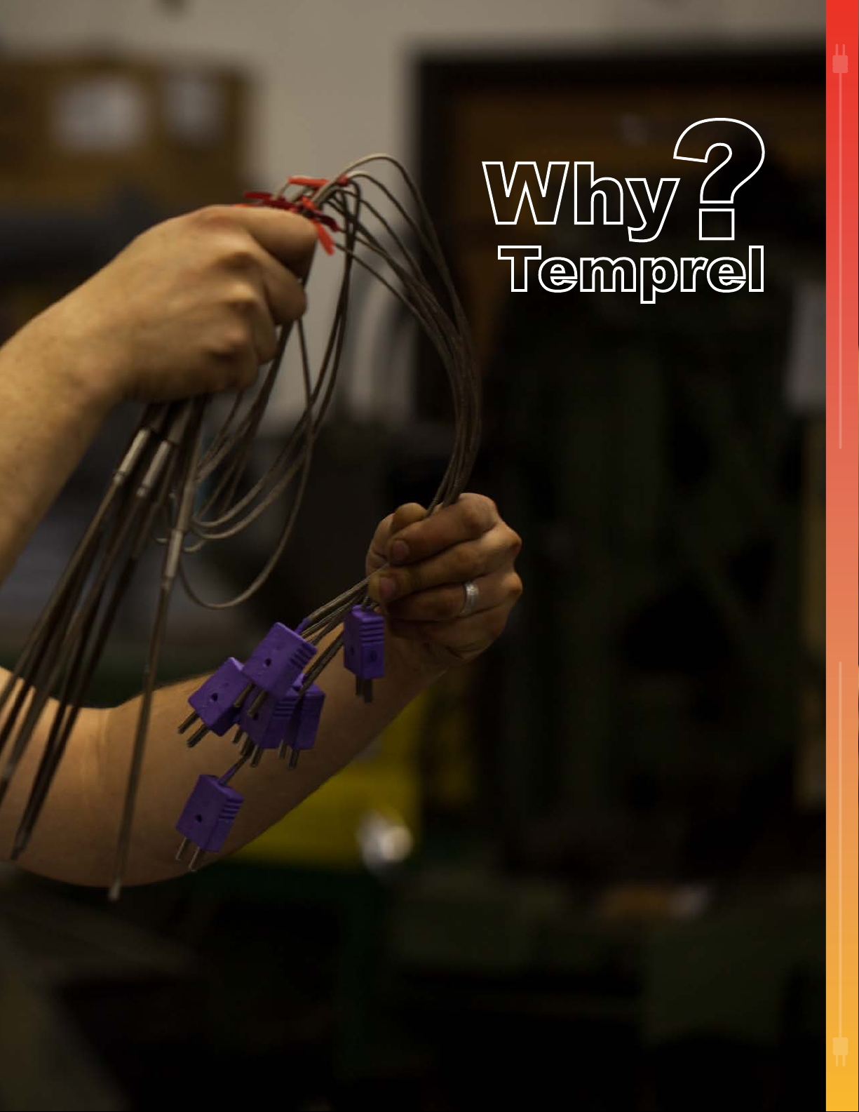
WHY TEMPREL?
Temprel’s website (Temprel.com) oers
customers the ability to view stock levels and
purchase products on-line as well as oering
thermocouple information and technical support.
2
3

About Us ..................................................................................................
Index ........................................................................................................
T21 Thermocouples .................................................................................
T23 Thermocouples .................................................................................
T24 Thermocouples .................................................................................
T25 Thermocouples .................................................................................
T26 Thermocouples .................................................................................
T52 Thermocouples .................................................................................
T54 Thermocouples .................................................................................
T100 Thermocouples ...............................................................................
B52 Thermocouples .................................................................................
Egt Exhaust Gas T emperature Thermocouples .......................................
T26 Spark Plug Thermocouples ..............................................................
Rubbing Thermocouples .........................................................................
Connectors ..............................................................................................
Connector Panels ....................................................................................
Brass Hose Couplings .............................................................................
Compression Fittings ...............................................................................
Direct Weld Compression Fittings ...........................................................
Weld on Bungs ........................................................................................
Operating Range .....................................................................................
Color Codes ............................................................................................
Nominal Resistance ................................................................................
Available Calibrations ..............................................................................
Compacted MgO’s ..................................................................................
Measuring Junctions ...............................................................................
Response Time .......................................................................................
Thermocouple Wire ..................................................................................
Thermocouple Wire Construction Characteristics ........................................
Custom Applications ..................................................................................
Page 1-2
Page 3-4
Page 5-6
Page 7-8
Page 9-10
Page 11-12
Page 13-14
Page 15-16
Page 17-18
Page 19-20
Page 21-22
Page 23-24
Page 25-26
Page 27-28
Page 29-30
Page 31
Page 32
Page 33
Page 34
Page 34
Page 35
Page 35
Page 36
Page 36
Page 37
Page 38
Page 38
Page 39-40
Page 41-42
Back Cover
CATAL OG INDEX
INDEX
4
T
THERMOCOUPLES
21
5
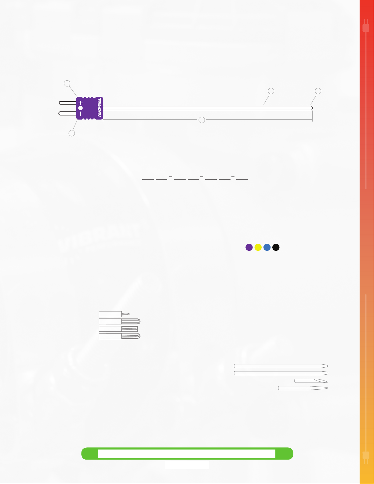
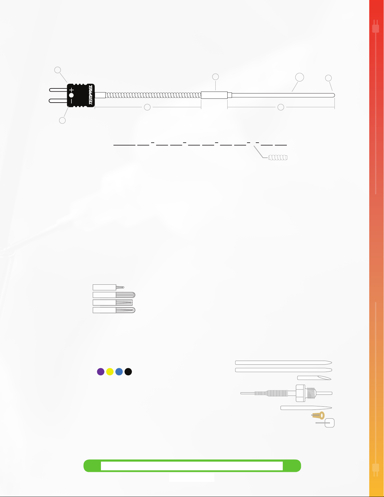
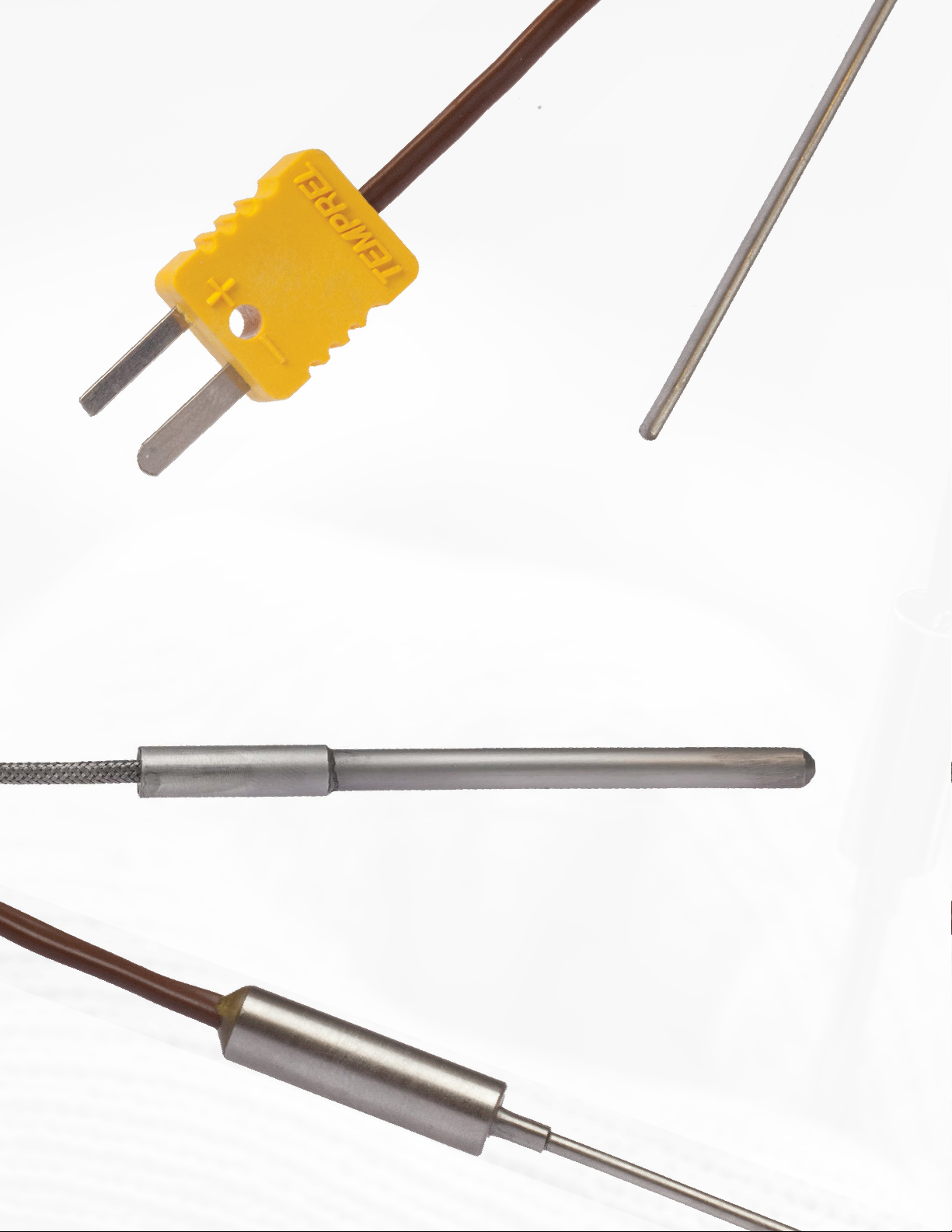
T21 CONFIGURATOR
Quick disconnect thermocouple with compacted MgO insulation
employing a glass-lled, nylon connector directly on the sheath.
1
7
3
4
Sample shown: T21-MU-6E-CI
2
Connectors#1
J -
Put On Standard-Jack
M -
Molded on Mini-Plug
MJ -
Put On Mini-Jack
MP -
Put on Mini-Plug
P -
Put on Standard-Plug
S -
Molded on Standard-Plug
Junction T ype
#2
E -
Exposed
G -
Grounded
S -
Semi-Shielded
U -
Ungrounded
U2 -
Ungrounded Separate for Dual Element
see page # 29-30
see page # 37-38
Specify Probe Length in Inches#3
Probe lengths may vary +/- .125” unless otherwise specied.
**
Probe length is measured from the tip of the
-
______
probe to the rst xed attachment.
T21 :
1 2 3 4 5 6
(Prex T21 Changes to D21 for Dual Element)
#5
AAA -
AA -
S10 S16 -
BP CP -
HPT -
RT -
7
Calibration#4
T JE K
Probe Diameter
.032”
(34 AWG wire)
.040”
(32 AWG wire)
A -
.062” 1/16”
B -
.090”
(25 AWG wire)
Probe Material#6
S -
304 Stainless Steel
310 Stainless Steel
316 Stainless Steel
(28 AWG wire)
C -
.125” 1/8”
D -
.188” 3/16”
E -
.250” 1/4”
see page # 37-38
I -
Inconel
H -
Hastelloy X
Available Options#7
Leave blank if none of the options listed below are needed.
**
Bullet Point
Cone Point
Hypodermic Point
Reduced Tip
(Sharpened to needle point)
( .125” to .062” diameter)
®
®
(22 AWG wire)
(19 AWG wire)
(16 AWG wire)
T21 THERMOCOUPLES
6
T
THERMOCOUPLES
23
7
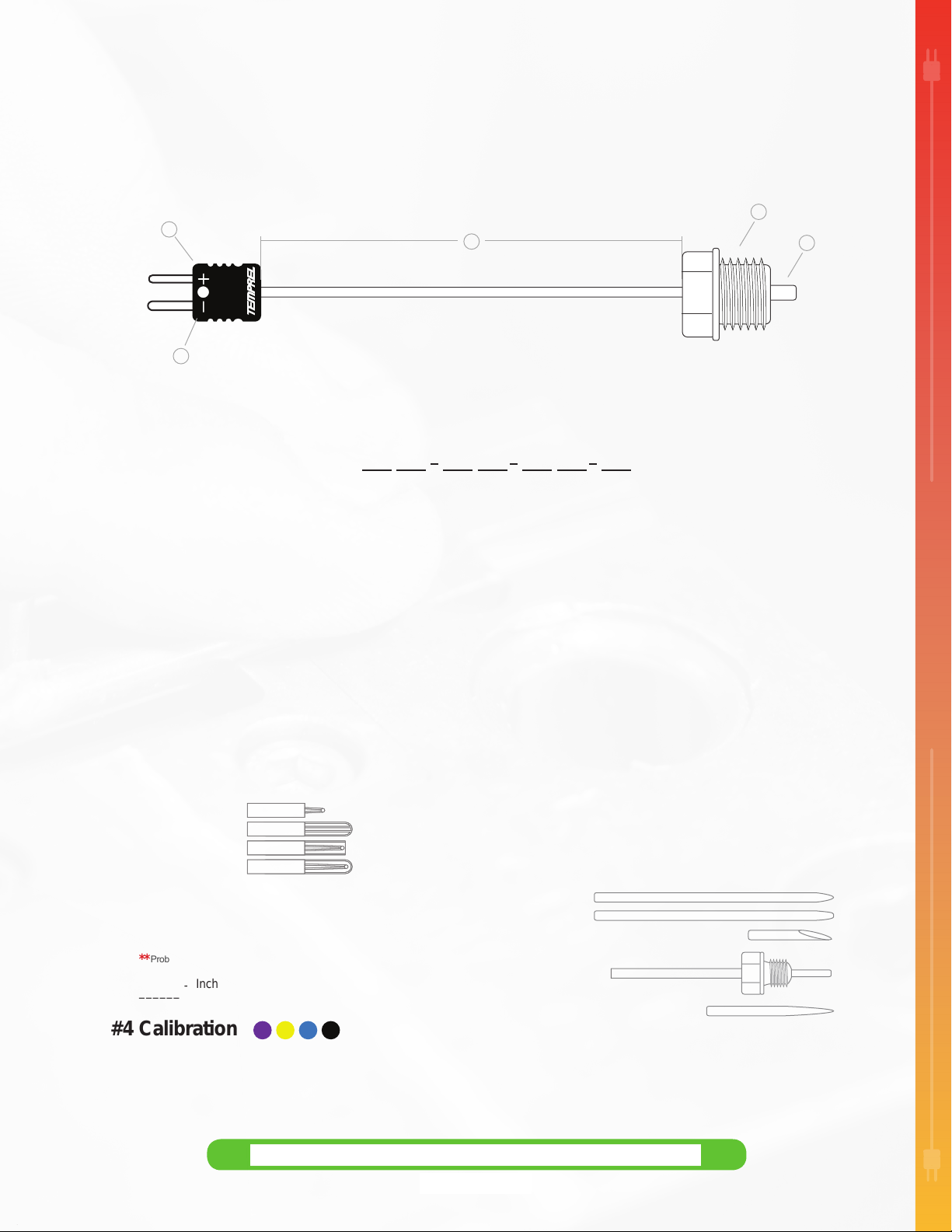
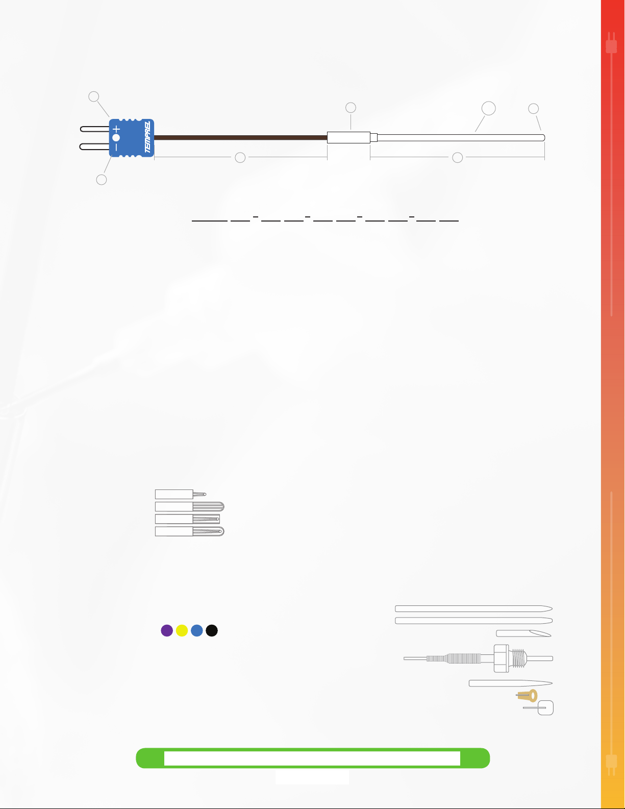
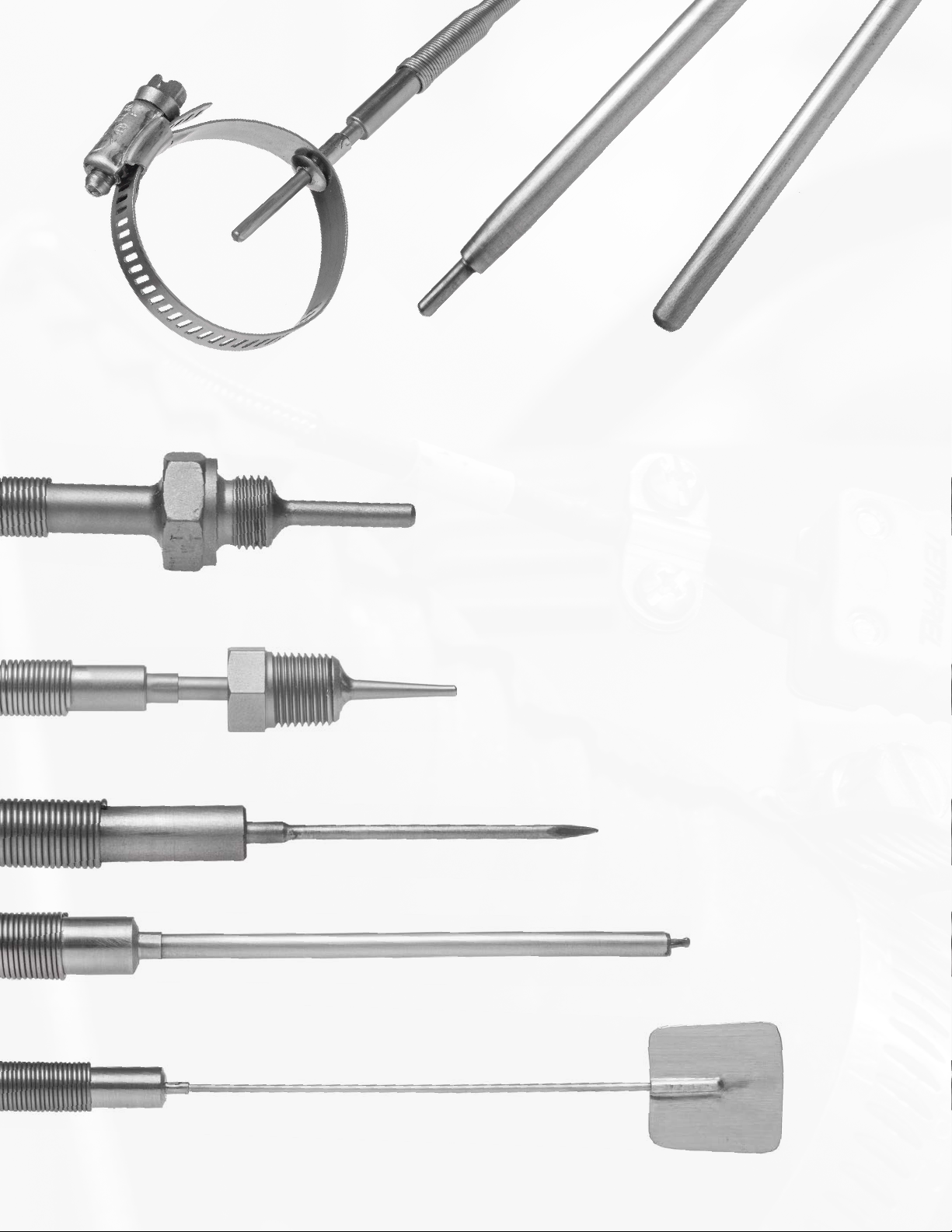
T23 CONFIGURATOR
Quick disconnect thermocouple with compacted MgO insulation
with a xed mount threaded tting mounted directly on the sheath.
7
1
4
Sample shown: T23-MU-6J-CS-14PP
3
2
Connectors#1
J -
Put On Standard-Jack
M -
Molded on Mini-Plug
MJ -
Put On Mini-Jack
MP -
Put on Mini-Plug
P -
Put on Standard-Plug
S -
Molded on Standard-Plug
Junction T ype
#2
E -
Exposed
G -
Grounded
S -
Semi-Shielded
U -
Ungrounded
U2 -
Ungrounded Separate for Dual Element
see page # 29-30
see page # 37-38
Specify Probe Length#3
Probe lengths may vary +/- .125” unless otherwise specied.
**
Inches
-
______
Calibration#4
T JE K
T23 :
1 2 3 4 5 6
(Prex T23 Changes to D23 for Dual Element)
#5
Probe Diameter
AAA -
.032”
(34 AWG wire)
AA -
.040”
(32 AWG wire)
A -
.062” 1/16”
B -
.090”
(28 AWG wire)
(25 AWG wire)
Probe Material#6
S -
304 Stainless Steel
S10 -
310 Stainless Steel
S16 -
316 Stainless Steel
Available Options#7
Custom ttings options available. Call Temprel to learn more.
**
Leave blank for standard probe tip.
BP -
Bullet Point
CP -
Cone Point
HPT -
Hypodermic Point
18PP -
1/8” Pipe Plug
14PP -
1/4” Pipe Plug
38PP -
3/8” Pipe Plug
RT -
Reduced Tip
7
C D E -
see page # 37-38
I -
Inconel
H -
Hastelloy X
(Sharpened to needle point)
( .125” to .062” diameter)
.125” 1/8”
.188” 3/16”
.250” 1/4”
®
®
(22 AWG wire)
(19 AWG wire)
(16 AWG wire)
T23 THERMOCOUPLES
8
T
THERMOCOUPLES
24
9
T24 CONFIGURATOR
A sheathed thermocouple with compacted MgO insulation, utilizing a heavy duty
transition tting and lead protected by stainless steel interlocking armor.
(Stainless steel interlocking armor comes standard with T24.)
1
7
4
Sample shown: T24-MU-4J-CS-LC4-A-2F
10
38
2
T24 :
1 2
Connectors#1
J -
Put On Standard-Jack
M -
Molded on Mini-Plug
MJ -
Put On Mini-Jack
MP -
Put on Mini-Plug
O -
Open Wire end, No Connector Option
OC -
Open Wire
P -
Put on Standard-Plug
S -
Molded on Standard-Plug
S3 -
Molded on 3 Prong Standard-Plug
T -
Terminals
Junction T ype
#2
E -
Exposed
G -
Grounded
S -
Semi-Shielded
U -
Ungrounded
U2 -
Ungrounded Separate for Dual Element
#3
Specify Probe Length in Inches
Probe lengths may vary +/- .125” unless otherwise specied.
**
Probe length is measured from the tip of the
-
______
probe to the rst xed attachment.
Calibration#4
#5
Probe Diameter
AAA -
.032”
(34 AWG wire)
AA -
.040”
(32 AWG wire)
A -
.062” 1/16”
B -
.090”
(25 AWG wire)
see page # 29-30
(wire blunt cut)
(Specify type & size when placing your order)
see page # 37-38
T JE K
C -
.125” 1/8”
D -
.188” 3/16”
(28 AWG wire)
E -
.250” 1/4”
3 4 5 6
(Prex T24 Changes to D24 for Dual Element)
Probe Material#6
S -
304 Stainless Steel
S10 -
310 Stainless Steel
S16 -
316 Stainless Steel
Transition#7
LA -
Stainless Steel with High Temperature Epoxy (600
LC -
Stainless Steel with High Temperature Ceramic Potting (2800
LE -
Stainless Steel with Epoxy Potting (500
Specify Wire Length in Inches#8
-
______
Wire Insulation#9
(solid wire)
2F
(solid wire)
2G
(solid wire)
2K
(solid wire)
2P
(solid wire)
2T
Available Options#10
Leave blank for standard probe tip.
**
BP -
Bullet Point
CP -
Cone Point
HPT -
Hypodermic Point
18PP -
1/8” Pipe Plug
14PP -
(22 AWG wire)
(19 AWG wire)
(16 AWG wire)
38PP -
RT -
W -
WP -
1/4” Pipe Plug
3/8” Pipe Plug
Reduced Tip
Washer
Weld Pad
A
7 8 9 10
Interlocking Armor
see page # 37-38
I -
H -
Length as measured from transition to the connector.
(stranded wire)
4F
(stranded wire)
4G
(stranded wire)
4K
(stranded wire)
4P
(stranded wire)
4T
( .125” to .062” diameter)
(Only available with .062“ or 1/16” probe diameter)
(Only available with .062” or 1/16” probe diameter)
- Fiberglass
- High Temp Fiberglass
- Polyimide
- PVC
- Fluoropolymer FEP
(Sharpened to needle point)
®
Inconel
Hastelloy X
®
o
F)
o
F)
o
F)
T24 THERMOCOUPLES
10
T
THERMOCOUPLES
25
11
T25 CONFIGURATOR
Flexible lead wire transition joint sheathed thermocouple with compacted MgO insulation,
utilizing a heavy duty transition tting and lead protected by stainless steel wire overbraid.
1
7
10
2
4
T25 :
Connectors#1
Multiple connectors may be selected. Not all combinations available.
**
J -
Put on Standard-Jack
JSR -
Put on Standard-Jack with Strain Relief
M -
Molded on Mini-Plug
MJ -
Put on Mini-Jack
MJSR -
MPSR -
Put on Mini-Jack with Strain Relief
MP -
Put on Mini-Plug
Put on Mini-Plug with Strain Relief
O -
Open Wire end, No Connector Option
OC -
Open Wire
P -
Put on Standard-Plug
PSR -
Put on Standard-Plug with Strain Relief
S -
Molded on Standard-Plug
S3 -
Molded on 3 Prong Standard-Plug
T -
Terminals
Junction T ype
#2
E -
Exposed
G -
Grounded
S -
Semi-Shielded
U -
Ungrounded
U2 -
Ungrounded Separate for Dual Element
see page # 29-30 see page # 37-38
(wire blunt cut)
(Specify type & size when placing your order)
see page # 37-38
Specify Probe Length in Inches#3
Probe lengths may vary +/- .125” unless otherwise specied.
**
Probe length is measured from the tip of the
-
______
Calibration#4
#5
Probe Diameter
AAA -
AA -
A -
B -
probe to the rst xed attachment.
.032”
(34 AWG wire)
.040”
(32 AWG wire)
.062” 1/16”
.090”
(28 AWG wire)
(25 AWG wire)
T JE K
C D -
E -
8
Sample shown: T25-MU-4T-CS-LE4-4T
1 2 3 4 5 6
(Prex T25 Changes to D25 for Dual Element)
S10 S16 -
HPT -
18PP 14PP -
.125” 1/8”
.188” 3/16”
.250” 1/4”
(22 AWG wire)
(19 AWG wire)
(16 AWG wire)
38PP -
WP -
3
7 8 9 10
Probe Material#6
S -
304 Stainless Steel
310 Stainless Steel
316 Stainless Steel
I -
H -
®
Inconel
Hastelloy X
®
Transition#7
LA -
Stainless Steel with High Temperature Epoxy (600
LC -
Stainless Steel with High Temperature Ceramic Potting (2800
LE -
Stainless Steel with Epoxy Potting (500
GP -
Overbraid Grounded to Transition
P -
Molded on Plastic Rated (525
o
F)
o
F)
Specify Wire Length in Inches#8
-
______
Length as measured from transition to the connector.
Wire Insulation#9
Append prex “R” to the begining of any options listed below to call for
**
Stainless Steel Overbraid on wire. Example “R4F”
(solid wire)
2F
(solid wire)
2G
(solid wire)
2K
(solid wire)
2P
(solid wire)
2T
4F
4G
4K
4P
4T
(stranded wire)
(stranded wire)
(stranded wire)
(stranded wire)
(stranded wire)
- Fiberglass
- High Temp Fiberglass
- Polyimide
- PVC
- Fluoropolymer FEP
Available Options#10
Leave blank for standard probe tip.
**
BP -
Bullet Point
CP -
Cone Point
Hypodermic Point
1/8” Pipe Plug
1/4” Pipe Plug
3/8” Pipe Plug
RT -
Reduced Tip
W -
Washer
Weld Pad
(Only available with .062“ or 1/16” probe diameter)
(Sharpened to needle point)
( .125” to .062” diameter)
(Only available with .062” or 1/16” probe diameter)
o
F)
o
F)
T25 THERMOCOUPLES
12
T
THERMOCOUPLES
26
13
 Loading...