

Page 1
Installation
Operation
Maintenance
Controls
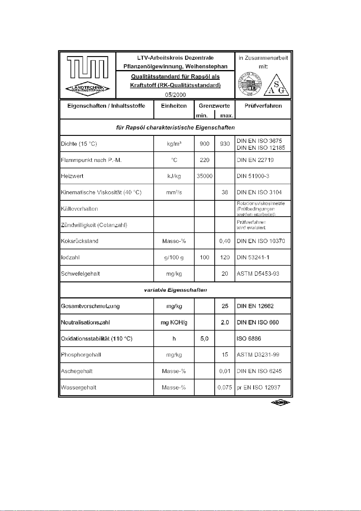
TEMPRATEC C1
Compressed Air Atomizing Burner for
Rapeseed Oil and Heating Oil EL
Page 2

TEMPRATEC C1
Contents
Page
1. Technical Data ................................................................................................................. 3
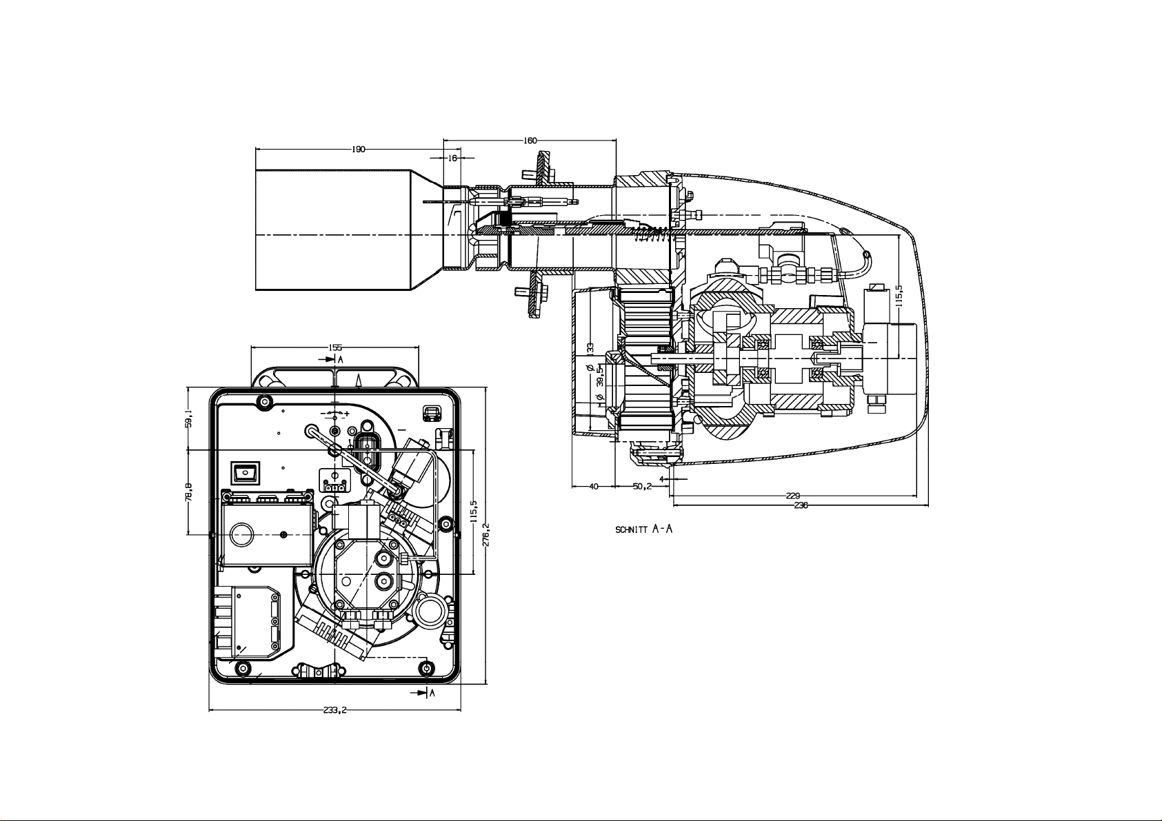
2. Dimensions ...................................................................................................................... 4
3. Warnings and Safety Precautions .................................................................................... 5
4. Installation of the Oil Burner ............................................................................................. 6
5. Items to remember when putting equipment into service ................................................. 7
6. Burner settings ................................................................................................................. 8
7. Basic Burner Settings ...................................................................................................... 9
8. Hydraulics Diagram .......................................................................................................... 10
9. Electrical Connections and Switching Diagram ................................................................ 11
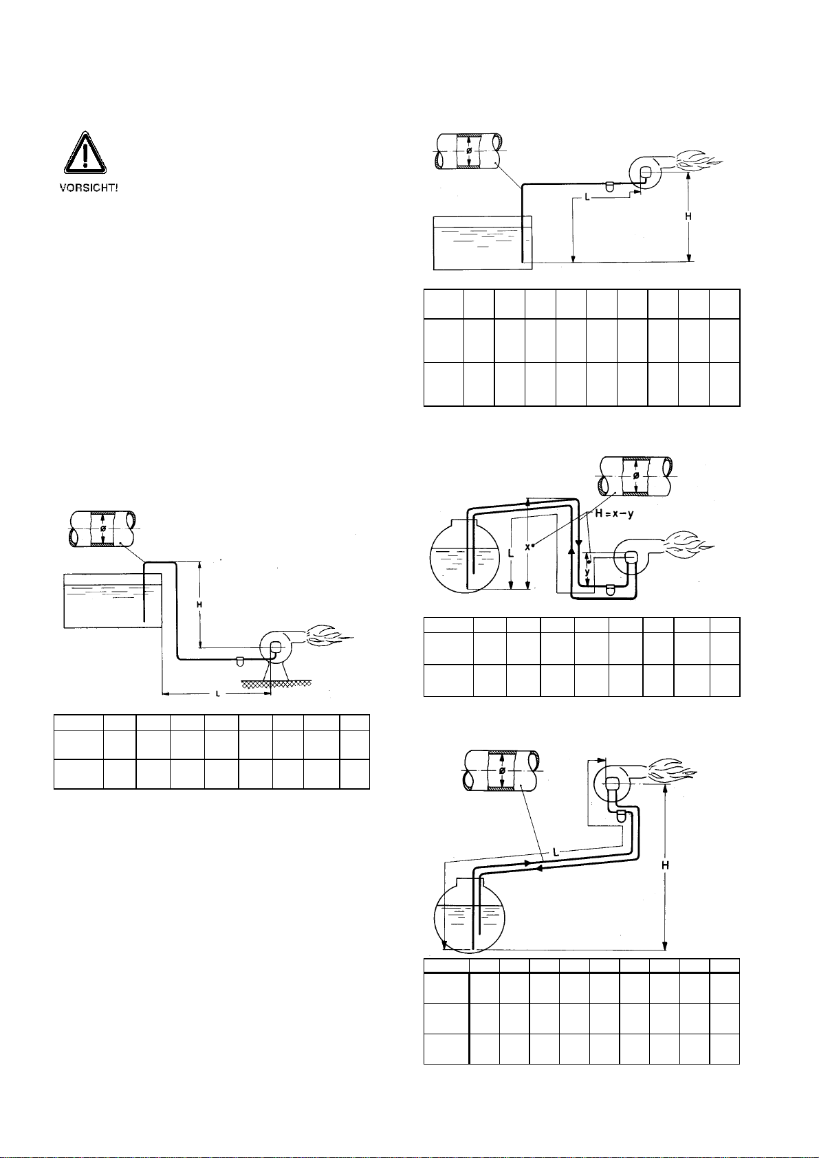
10. Oil Connection (Pipeline Dimensions)............................................................................... 12
11. Burner Malfunctions and Possible Causes ....................................................................... 14
12.
Care and Maintenance ..................................................................................................... 15
13.
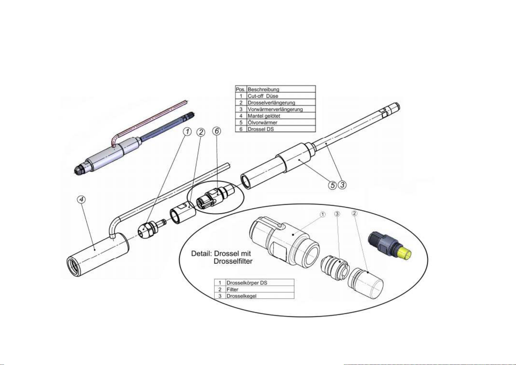
Nozzle Holder................................................................................................................... 16
14. Putting Equipment Out of Service .................................................................................... 17
15. Guarantee Conditions ..................................................................................................... 17
16. Oil Quality, Rapeseed Oil ................................................................................................. 18
17.
Manufacturer Declaration and Declaration of Conformity ................................................. 19
18.
Installation Instructions .................................................................................................... 20
19.
Putting into service ........................................................................................................... 23
20.
Service Instructions .......................................................................................................... 25
- 2 -
Page 3
1. Technical Data
TEMPRATEC C1
- 3 -
Page 4
2. Dimensions
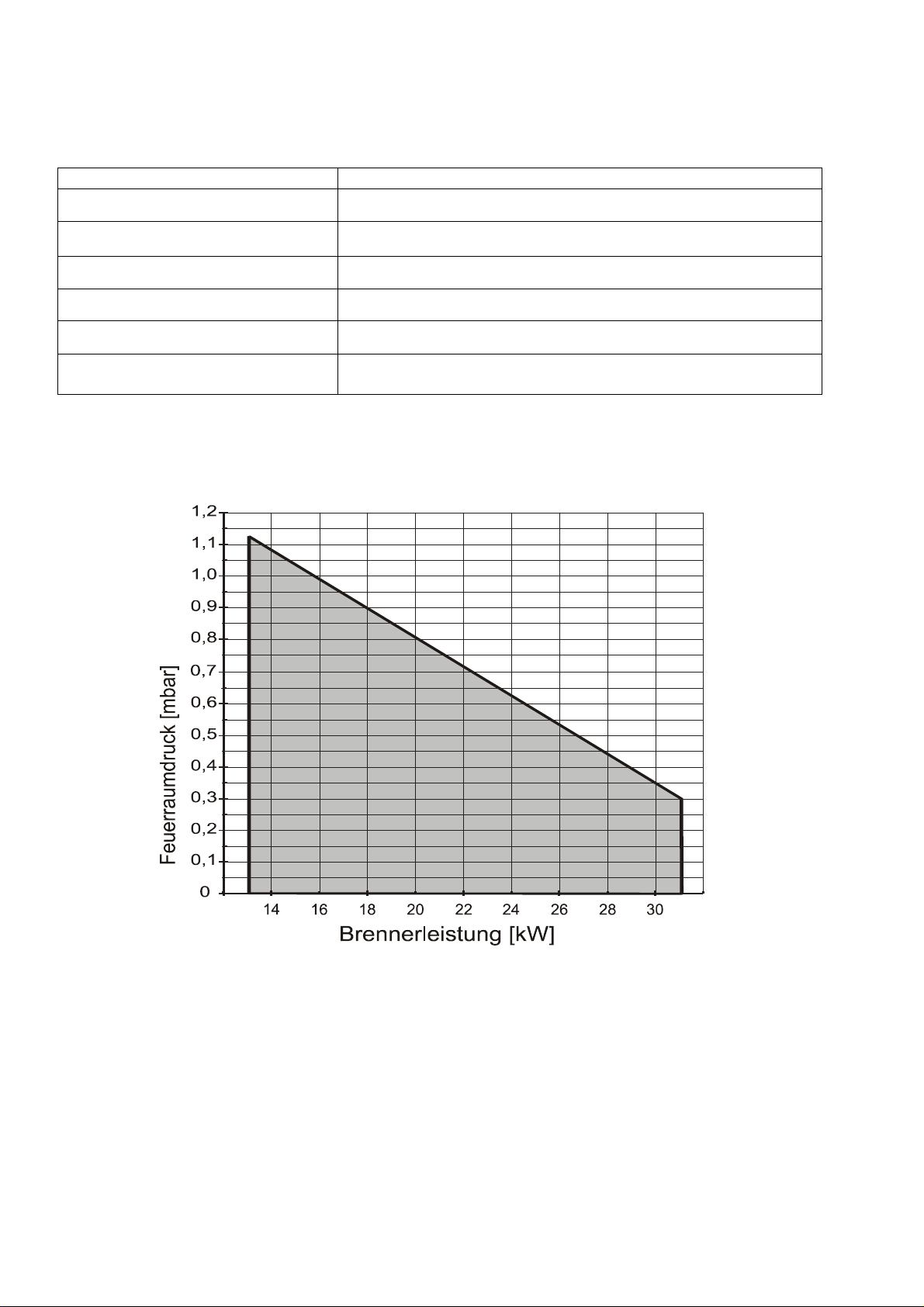
Burner type Tempratec C1
Burner output 13 - 31 kW
Oil throughput, heating oil EL 1.1 - 2.6 kg/ h
Oil throughput, rapeseed oil 1.3 - 2.9 kg/ h
NOx Class 3
Electrical power consumption 305 W
TEMPRATEC C1
Basis for testing
Performance diagram:
Combustion chamber pressure [mbar] Burner output [kW]
DIN EN 267 (99)
1. BImSchV
We reserve the right to make changes conducive to technical advances.
- 4 -
Page 5

TEMPRATEC C1
Shutting down of burner for a given
3. Warnings and Safety Precautions
IMPORTANT NOTICE
Carefully read the installation
instruction for the burner before
installation and putting into service.
Non-compliance or improper
installation renders the warranty nil
and void.
When installing accessory
components, follow the
corresponding instructions.
DANGER
WARNING!
due to electric current.
Before undertaking any work on the
burner and heating equipment, cut
off all electric power, e.g. by means
of the heater emergency OFF switch
outside the furnace room. Switching
off the regulating device is not
sufficient!
EQUIPMENT DAMAGE
CAUTION!
due to improper installation. Please
comply with engineering standards
as well as building and other legal
regulations regarding construction
and operation of the equipment!
EQUIPMENT DAMAGE
CAUTION!
This burner is equipped for use with
biological fuels with special
components.
Use only original spare parts.
EQUIPMENT DAMAGE
CAUTION!
due to improper cleaning and
maintenance. Perform cleaning and
maintenance steps as instructed,
whereby the entire system must be
tested for faultless functioning!
Eliminate any defects immediately to
avoid damaging the equipment!
IMPORTANT NOTICE
CONCERNING OIL STORAGE
For vegetable oils, storage
temperatures higher than 20°C and
lower than 8°C must be avoided.
Avoid exposure to light. Oil must be
removed from storage via a floating
device to guarantee sediment-free
oil quality. Oil storage, including
laying of the oil lines, must be
realized in such a manner that the
oil temperature upstream from the
burner is at least + 8°C .
IMPORTANT NOTICE
CONCERNING OIL TANK FILLING
The oil burner must be switched off
before filling the tank. To allow
floating particles to settle, it is
necessary to wait approx. 3 h after
filling before switching on the oil
burner again.
In case of leaky oil lines or an empty
tank, deflagrations may occur due to
air bubble formation.
period
If the heating system is being run on
vegetable oil, the burner must be
flushed with the fuels EL (extra light)
heating oil or automotive diesel for at
least 10 minutes before shutting
down the system for periods longer
than 14 days.
We reserve the right to make technical
changes!
Illustrations, functional steps and technical data
may deviate slightly due to ongoing
developments.
- 5 -
Page 6
TEMPRATEC C1
4. Installation of the Oil Burner
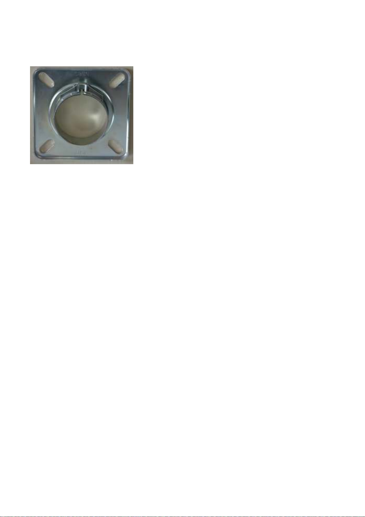
The sliding flange supplied with the equipment is
used to affix the oil burner to the boiler by means
of four bolts for attachment to the boiler plate.
The jam-fit sliding flange facilitates insertion of
the fire tube into the combustion chamber so as
to meet the requirements of the specific boiler
unit.
The slots in the sliding flange are suitable for
reference diameters from 150 to 180 mm.
When installing the sliding flange, take into
account the tilt of 3° in the direction of the
combustion chamber so that no oil will flow into
the burner when the preheater is warming up.
Comply with the label instruction "TOP"!
Once the flange has been mounted on the boiler,
the fire tube is inserted and the burner is raised
slightly and fitted tight. (4 mm Allen key).
The combustion chamber door is then opened
and the fire tube is fastened down using the
bayonet mount.
4.1 Insertion depths
In some combustion chamber versions,
predefined fire tube insertion depths must be
complied with:
Threepass boiler with recirculation
combustion chamber:
Insert burner until the recirculation slits project
into the combustion chamber insert.
Hot reversed-operation combustion chamber:
Insert burner only until the recirculation slits are
flush with the door insulation.
Very important:
It is important to make sure the recirculation slits
project far enough into the combustion chamber
to ensure exhaust gas recirculation. They must
not be covered by insulation material. The
distance between the rear wall of the boiler and
the must be at least 100 mm.
4.2 Electrical connection
The electrical connection is realized by means of
a plug-in connector acc. to DIN EN 226, the
socket component of which is attached to the
burner. Comply with local EVU and VDE
regulations. Comply with switching diagram!
Pull out burner plug before working on the burner
electrical system.
4.3 Oil connection
The oil hoses provided are connected to the oil
pump and affixed with the clamping device. The
cutoff and filter fixtures must be arranged to
provide for technically appropriate hose
arrangement, i.e. the hoses must not be buckled.
Please use only the oil hoses included with the
equipment and original replacement parts. Only
these hoses will ensure optimized resistance to
aggressive acids contained in the biological
fuels. Use parts made of plastic or special steel
for all parts in contact with oil.
- 6 -
Page 7

TEMPRATEC C1
5. Items to remember when putting equipment
into service
5.1 Exhaust gas temperature
The exhaust gas temperature should be within
the range of 160°C to 200°C. At temperatures
below 160°C there is a risk of condensate
sooting. It is therefore important to make sure the
stack meets the relevant specifications. The
instructions issued by the boiler manufacturer on
minimum exhaust gas temperature must also be
complied with.
5.2 Harmonization of burner, boiler and stack.
A prerequisite of faultless combustion is a
constant combustion chamber pressure, since
the burner fan output depends on a certain
counterpressure level. Pressure variations result
in air excess or deficiency. Installation of a
draught restriction valve or secondary air
system is necessary to achieve a constant
combustion chamber pressure. The stack crosssection dimension must also be appropriate.
Stack and burner monitoring and heating
engineers can provide technical expertise
concerning the dimensioning of stacks and
secondary air systems.
5.3 Exhaust gas thermometer
Installation of an exhaust gas thermometer or
continuous monitoring of the exhaust gas
temperature using thermometers available from
technical suppliers is recommended. An
appropriate measuring point is the control
opening for stack and burner engineers in the
exhaust gas tube. A rise in exhaust gas
temperature exceeding 30°C indicates initial
formation of deposits in the boiler, which result in
sub-optimum operation of the heating system.
The burner setting should be controlled and
cleaning of the boiler considered. Reference
measurements must ensure that the boiler
temperatures are identical and that the burner
operating times prior to measurement are
approximately the same.
5.4 Operation timer
To control oil consumption, it is recommended
that the C1 burner be supplied with an operation
timer. When comparing oil consumption levels, it
must be taken into account that the external
temperature curve over given months or years
influences the measurement results.
5.5 Fuels
The Tempratec C1 burner is tested and
approved for the fuels heating oil EL and
rapeseed oil acc. to E-DIN 51605:2005-06 (RK
Quality Standard).
5.6 Information concerning the operations
room
The burners may only be installed in rooms in
which air contamination with halogenated
hydrocarbons can be expected, such as
hairdresser businesses, printing businesses,
chemical dry-cleaners, laboratories, etc. if a
sufficient volume of uncontaminated combustion
air is available. The burners may not be operated
in rooms with high levels of dust or humidity, e.g.
washrooms. The heating room must be protected
from frost and well ventilated. If these principles
are not complied with, warranties for any
damages will be nil and void.
- 7 -
Page 8
TEMPRATEC C1
6. Burner settings:
The C1 burner features the following settings:
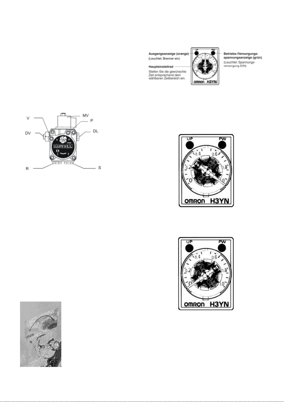
6.1. The pump pressure adjustment
Pump pressure adjustment (DV) is used to set
the performance level over the entire
performance range.
The nozzle need not be replaced to change
the output performance level.
S = Suction line
P = Manometer, pump pressure
DV = Pressure adjustment
MV = Solenoid valve
R = Recirculation line
V = Vacuum meter
DL = Nozzle line
The pump pressure covers a range of:
3.0 – 13.5 bar for heating oil EL
5.5 – 18.0 bar for rapeseed oil
6.2. Air valve adjustment
The air valve is adjusted to adapt the combustion
air to the oil volume (output).
Excessive combustion air is
controlled by means of the air
valve using a suitable
emissions metering device.
Non-binding basic settings
are listed in the table “Basic
Settings”.
6.5. Startup delay
Output display (orange) Operational / supply voltage
(lights up: burner on) display (green)
Main adjustment wheel (lights up: voltage supply ON)
Set time accordingly.
During the adjustable startup delay time, the
temperature of the entire nozzle holder is
monitored to make sure it is high enough before
the burner starts up.
Basic setting for startup delay:
Time setting (t): approx. 10 min.
Turn knob to the right until it hits the stop.
To undertake service work on the
operationally warm burner, the settings wheel
can be turned to the right until it hits the stop.
This reduces the startup delay to 1 min..
After the service work is completed, the settings
wheel is always once again turned to the right
until it hits the stop to avoid startup problems.
- 8 -
Page 9
TEMPRATEC C1
7. Basic Burner Settings
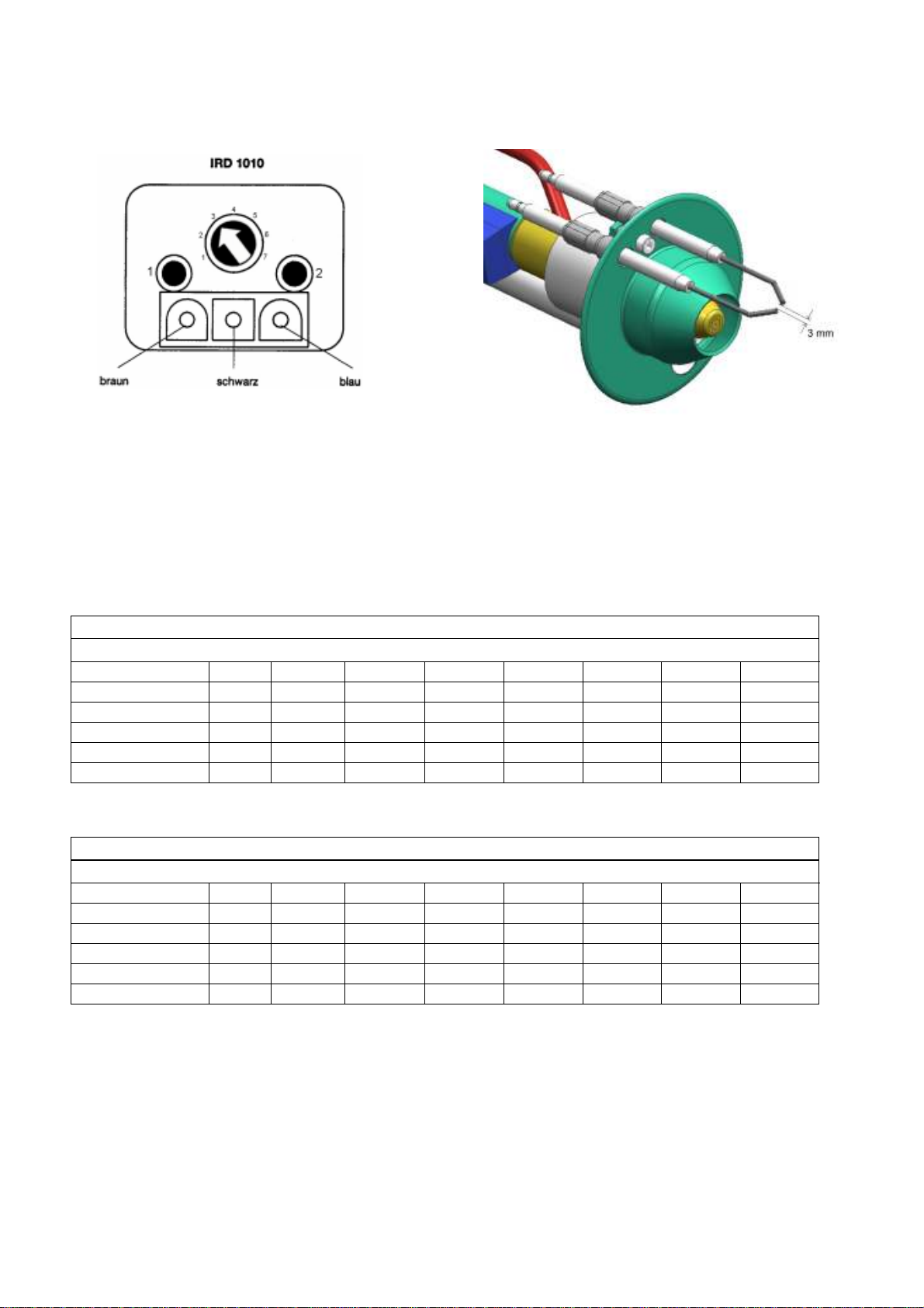
6.6 The infrared flicker detector (IRD)
6.7. Ignition electrodes
The infrared flicker detector facilitates detection
of blue flames. The basic setting is position "3"
The form and gap of the ignition electrode can be
determined using this drawing.
The burner output, with the corresponding, non-binding, data for pump presure and air settings, can be
read off the following table.
The measured values were obtained with oil at an approx. temperature of 20°C.
Heating oil
Non-binding data
Output range [kW] 13 16 19 22 25 28 31
Oil througput [kg/h] 1.1 1.3 1.6 1.8 2.1 2.4 2.6
Pump pressure [bar] 4 5 6 8 10 13 15
Pos. inlet nozzle [Skala] max. max. max. max. max. max. max.
Pos. air valve [mm] 5 7 9 10 11 13 14
Mixed pressure [mbar] 1.6 2 3 4.3 5.3 6.8 7.9
Restsauerstoffgehalt [O2] ca. 2.5 %
Rapeseed oil
Non-binding data
Output range: [kW] 13 16 19 22 25 28 31
Oil througput: [kg/h] 1.3 1.6 1.8 2.1 2.4 2.7 2.9
Pump pressure: [bar] 5 8 10 11 13 16 18
Pos. inlet nozzle: [Skala] max. max. max. max. max. max. max.
Pos. air valve: [mm] 6 9 10 11 12 13 14
Mixed pressure: [mbar] 1.4 3 4.1 4.4 5.9 6.6 7.1
Residual oxygen content [O2] approx. 2.5%
These values are used for presettings only.
An emissions measurement must be carried out in any case and the combustion air volume
must be adjusted using the air valve.
Emissions must be remeasured when the fuels are changed.
- 9 -
Page 10
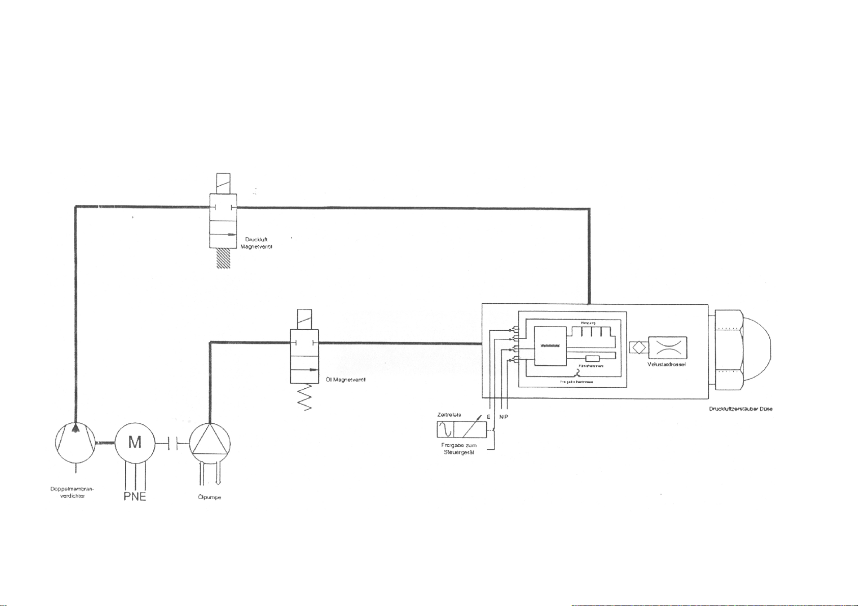
8. Hydraulics Diagram
TEMPRATEC C1
- 10 -
Page 11
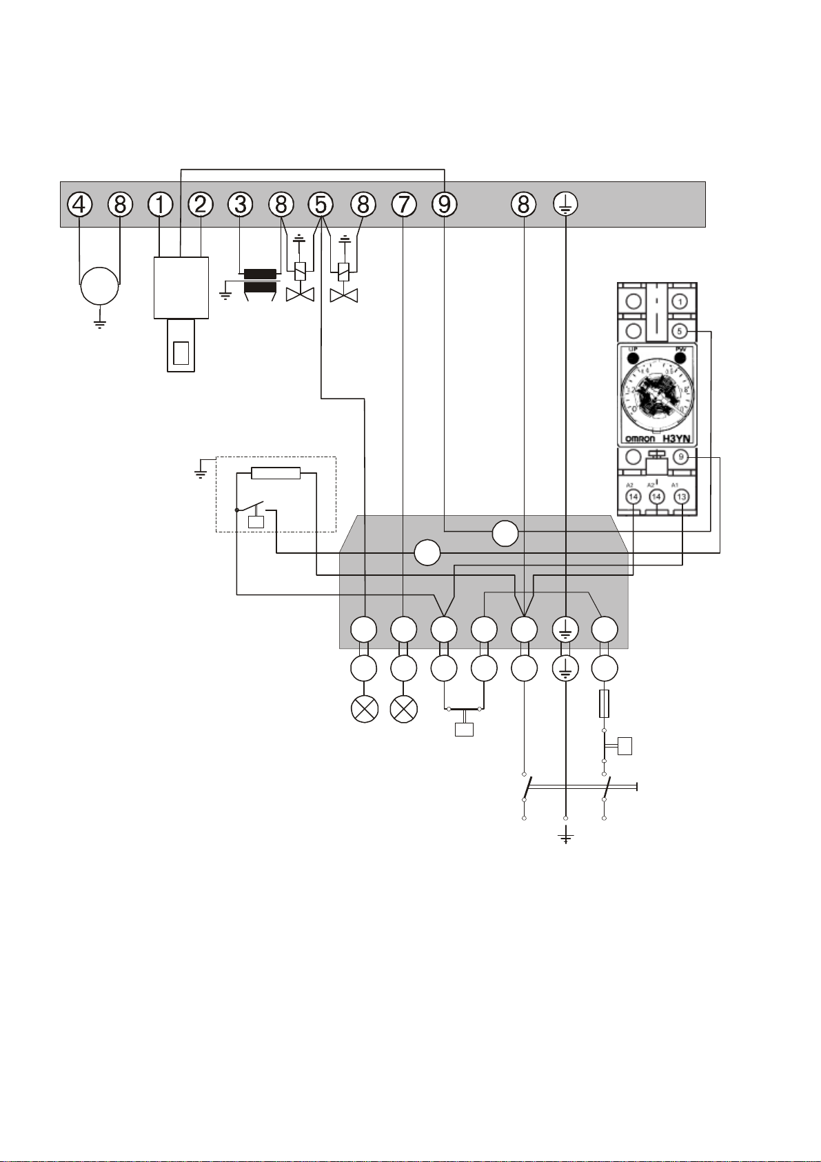
9. Electrical Connections and Switching Diagram
S3NT2T11
B4
M
a
g
n
e
t
v
e
n
t
i
l
Öl
Z
ü
n
d
t
r
a
f
o
M
o
t
o
r
S3NT2T11
B4
N
L
STB
6 A
Haupt-
schalter
230 V ~ 50 Hz
- Vielfachstecker -
Feuerungsautomat
S2
A
n
s
p
r
e
c
h
v
e
r
z
ö
g
e
r
u
n
g
M
a
g
n
e
t
v
e
n
t
i
l
L
u
f
t
swbrb
l
S1
M
~
IRD
1010
Ölvorwärmer
sw
br
bl
(Betriebsstundenzähler)
Betrieb
Störung
TEMPRATEC C1
DKO 970
brennerseitig
anlagenseitig
Temperaturregler
(Thermostat)
- 11 -
Page 12
TEMPRATEC C1
10. Oil Connection
EQUIPMENT DAMAGE
CAUTION!
This burner is suitable for use with
biological fuels.
Handle these fuels using suitable
materials
steel).
(e.g. plastic or special
Carry out installation in accordance with the valid
engineering regulations, applying the specified
safety devices, e.g. anti-lift valve.
In general, a onepass oil supply with an
automatic onepass deaeration filter is
recommended.
10.1 Pipe dimensioning for heating oil EL with a
viscosity of 4.8 mm²/s (20°C)
1-pass system with elevated tank
1-pass system with tank at lower level
H
0.0 0.5 1.0 1.5 2.0 2.5 3.0 3.5 4.0
[m]
Ø 4
[mm
52 46 40 33 27 21 15 9 2
]
Ø 6
[mm
100 100 100 100 100 100 75 44 12
]
2-pass system with elevated tank
H [m] 4.0 3.5 3.0 2.5 2.0 1.5 1.0 0.5
Ø 4
[mm]
Ø 6
[mm]
51 45 38 32 26 19 13 6
100 100 100 100 100 97 65 32
H [m] 4.0 3.5 3.0 2.5 2.0 1.5 1.0 0.5
Ø 6
[mm]
Ø 8
[mm]
33 31 29 27 25 23 21 19
100 98 91 85 79 72 66 60
2-pass system with tank at lower level
H [m] -0.0 -0.5 -1.0 -1.5 -2.0 -2.5 -3.0 -3.5 -4.0
Ø 6
[mm]
Ø 8
[mm]
Ø 10
[mm]
17 15 13 11 9 7 5 3 1
53 47 41 34 28 22 15 9 3
100 100 99 84 68 53 37 22 6
- 12 -
Page 13
TEMPRATEC C1
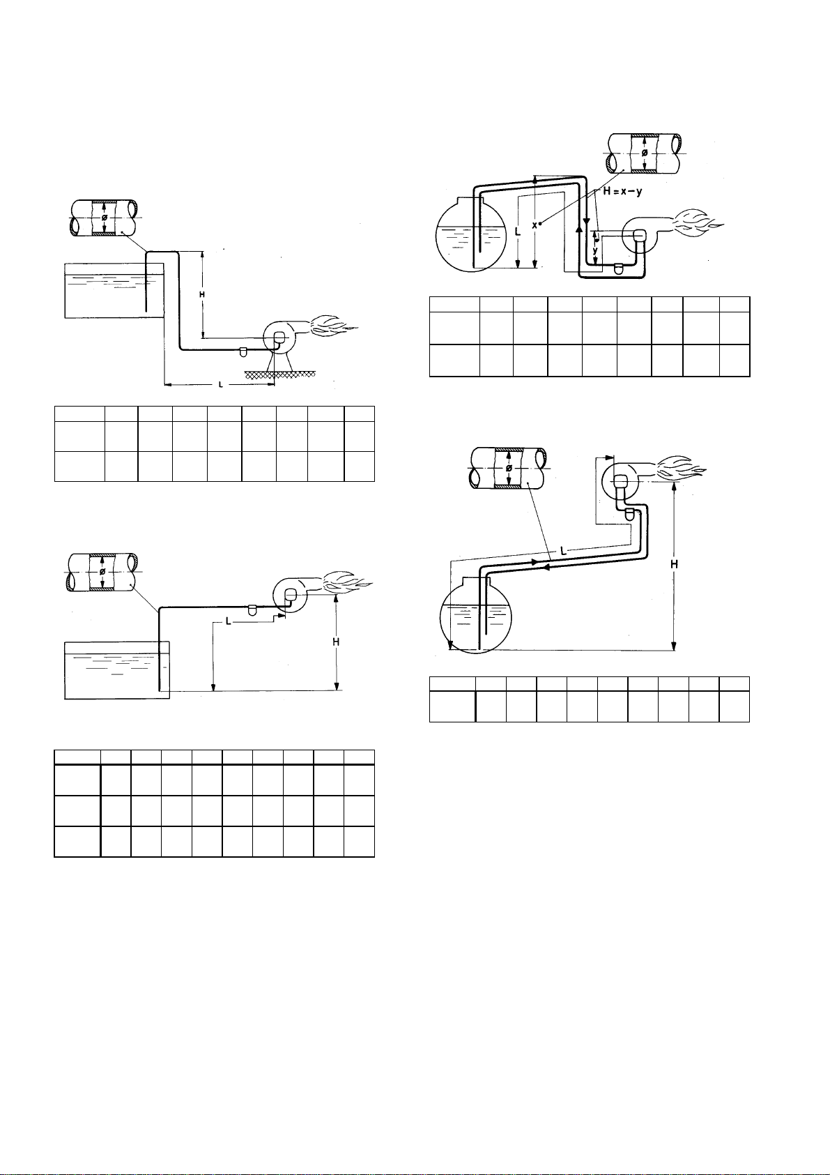
10.2 Pipe dimensioning for rapeseed oil with a
viscosity of 80 mm²/s (20°C)
1-pass system with elevated tank
H [m] 4.0 3.5 3.0 2.5 2.0 1.5 1.0 0.5
Ø 6
[mm]
Ø 8
[mm]
46 43 40 38 35 32 29 27
100 100 100 100 100 100 93 84
1-pass system with tank at lower level
2-pass system with elevated tank
H [m] 4.0 3.5 3.0 2.5 2.0 1.5 1.0 0.5
Ø 10
[mm]
Ø 12
[mm]
16 15 14 13 12 11 11 10
34 32 30 28 26 24 22 20
2-pass system with tank at lower level
H [m] -0.0 -0.5 -1.0 -1.5 -2.0 -2.5 -3.0 -3.5 -4.0
Ø 6
[mm]
Ø 8
[mm]
Ø 10
[mm]
22 19 17 14 12 9 7 4 -
68 60 53 45 37 29 22 14 6
100 100 100 100 91 72 53 34 15
H [m] -0.0 -0.5 -1.0 -1.5 -2.0 -2.5 -3.0 -3.5 -4.0
Ø 12
[mm]
16 14 13 11 9 7 5 - -
- 13 -
Page 14

TEMPRATEC C1
11. Burner Malfunctions and Possible Causes
Ask your heating engineer if you require further information.
Malfunction Cause Elimination
Motor does not start Fuse defective
System starts, but switches off (to
“defect” mode) after safety margin
time has elapsed
Flame goes out during operation
Sparking malfunctions Ignition sparkovers to nozzle or mixing device
Malfunction cause diagnosis with Satronic DKO automatic firing device
The diagnostic system provides continuous information concerning the current program phase of the device. External communications are
realized by means of a blink code. Additional information can be read out with the help of a "SatroPen".
Program progression display
The integrated microprocessor controls both the program
progression and the information system. The individual phases of
the program progression are displayed as blink codes. The
following messages are used:
= Short pulse
= Long pulse
= Short pause
_ = Long pause
*) = If present
Message Blink code Malfunction message Blinkcode Malfunction cause
Controlled preventilation (DKW)
Pre-ignition time
Safety marging and post-ignition time
Operation
Mains undervoltage
Safety thermostat "off"
Motor defective
Electric power supply line defective
Oil-preheater defective
Startup delay maladjusted
Startup delay defective
1. With flame production :
Flame monitory soiled, defective or with
incorrect setting
Control device defective
2. Without flame production :
Sensor "sees" ignition sparks (LEDs light up)
Ignition cable influences sensor line
Ignition defective
Ignition electrodes defective
Ignition cable connections loose
External light setting IRD too sensitive
External light on flame sensor
System is not supplied with oil:
Oil line valves closed
Oil tank empty
Filter soiled
Oil line leaky
Pump defective
Solenoid valve / control unit defective
Membrane compressor defective
Oil depleted
Oil filter or oil feeder line clogged
Oil pump defective
Air inclusions in oil line
Solenoid valve defective
Membrane compressor defective
Volustat filter clogged
Ignition defective
Malfunction cause diagnosis
The LED lights up continuously in case of a malfunction. This is
interrupted every 10 seconds and a blink code is sent that provides
information concerning the cause of the malfunction. This results in a
sequence as follows, which is repeated until the error is
acknowledged, i.e. until the malfunction is eliminated.
Lighting phase Dark phase Blink code Dark phase
10 sec. 0.6 sec. 1.2 sec.
_
Malfunction cutoff
External light
disturbance
Manual malfunction
cutoff
Replace
Switch on thermostat
Replace
Check
Replace
Test
Replace
Clean, replace, set
Replace
Block direct line of sight to sparks
Do not run cable parallel
Replace transformer
Replace electrodes
Check cable connections
Reduce IRD sensitivity
Switch off external light
Open
Replenish oil
Clean
Seal
Replace
Replace
Replace
Replenish oil
Clean filters, lines
Replace
Deaerate
Replace
Replace
Clean, replace
Correct ignition electrode position
Replace transformer
_
No flame recognition during
safety margin time
External light during preventilation, possibly
defective sensor
- 14 -
Page 15

12. Care and Maintenance
IMPORTANT
Shutting down of burner for a
EQUIPMENT DAMAGE
CAUTION!
due to a lack of or faulty cleaning
and maintenance.
Have entire heating system
maintained by a specialized
company once a year.
We recommend concluding a
contract for the annual maintenance
work.
12.1 Burner care
A moist towel an gentle household cleaning agent or
dishwashing liquid will suffice to cleaning the burner
surfaces. Do not use scouring agents. Switch off
current when cleaning the system.
12.2 Burner maintenance
Once a year, preferably before the heating period, the
burner and oil supply must be subjected to detailed
maintenance.
Switch off current when maintaining the system.
Maintenance items:
1. Clean all parts through which air flows to remove dust,
greasy coatings, etc.
2. Replace main oil filter units
3. Check all parts through which oil flows for leakage.
4. Clean combustion residues out of the mixing equipment.
5. Clean or check the ignition electrodes. Set gaps.
6. Blow out oil nozzle using compressed air.
7. Clean or replace throttle filter.
8. Clean photocell.
TEMPRATEC C1
If the burner is run on rapeseed oil,
the maintenance intervals are 3
months. An automatic heating oil
deaerator with integrated filter and
underpressure manometer is
recommended (e.g. Afriso FloCoTop-M, suitable for rapeseed oil).
This filter unit can be ordered as an
accessory.
given period
If the heating system is being run
on vegetable oil, the burner must
be flushed with the fuels EL (extra
light) heating oil or automotive
diesel for at least 10 minutes
before shutting down the system
for periods longer than 14 days.
- 15 -
Page 16
13. Nozzle Holder
TEMPRATEC C1
- 16 -
Page 17

TEMPRATEC C1
14. Putting Equipment Out of Service
EQUIPMENT DAMAGE due to
frost.
CAUTION!
The heating system may freeze
when exposed to frost if it is not in
operation. Protect the heating
system from frost. To do this, drain
out the heating water at the lowest
point on the heating system.
Points to remember when putting the equipment
out of service:
14.1 Putting out of service or during
maintenance:
Switch off the mains switch on the switching
console. Cut off the oil supply. Drain water out of
system if there is a danger of frost.
14.2 Emergency cutoff:
In emergencies, switch off the heater at the
emergency cutoff switch and stop fuel feed at
the next accessible cutoff valve.
IMPORTANT
If the burner is run on rapeseed oil,
brief operation with EL heating oil or
automotive diesel fuel is
recommended during putting out of
service to preserve the parts through
which oil passes (approx 10
minutes).
Due to its components, rapeseed oil
tends to resinify and clog up the
machine components over longer
standstill periods.
15. Guarantee Conditions
The general guarantee period for our equipment
is 24 months after delivery, beginning with the
billing date.
All guarantee claims lose their validity:
- If the device is not put into service in the
technically correct manner (must be
confirmed by measurement protocol).
- If regular maintenance as per the
TEMPRATEC Operating Instructions have not
been carried out an documented.
- Maintenance intervals:
- Annually if run on heating oil
- Quarterly if run on rapeseed oil
(Weihenstephan Quality Standard)
- If any fuel besides heating oil EL, DIN 516031 or rapeseed oil Quality Standard
Weihenstephan has been used.
- If heating oil or rapeseed oil has been stored
or used at below +8°C.
- If changes or manipulations of the equipment
have been carried out.
- If repair work has been done by persons who
are not specifically qualified.
- If the safety instructions and installation
instructions have not been complied with
- If the equipment is used in darkrooms, baking
ovens, annealing furnaces, drying cabinets or
for industrial purposes
- 17 -
Page 18
TEMPRATEC C1
- 18 -
Page 19
TEMPRATEC C1
- 19 -
Page 20
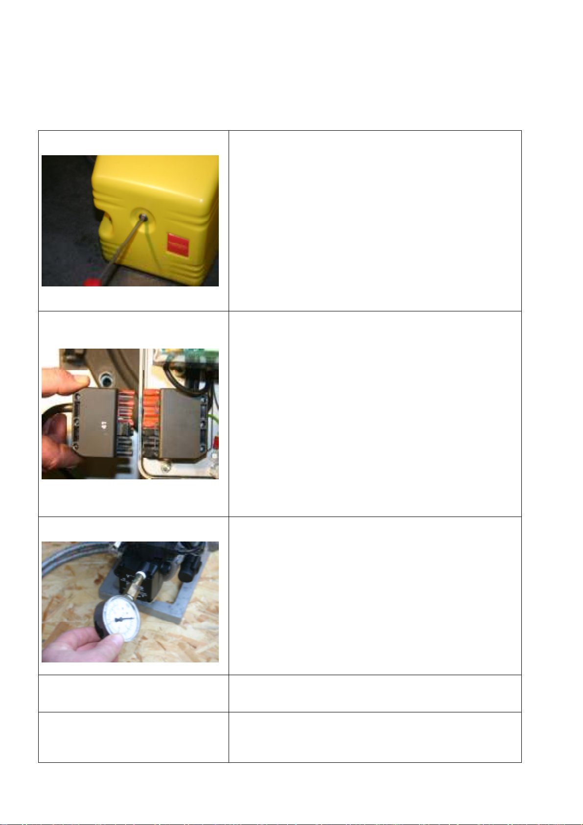
19. Putting into service
Step 1:
Step 2
TEMPRATEC C1
Loosen fastening bolt on C1 burner hood with screwdriver
and remove burner hood.
Please remember
Use large screwdriver.
Connect electrical power line from boiler to Euro plug on
C1 burner.
Step 3
Step 4
Step 5:
Burner oil pump: Screw out plug on the pump lid using the
Allen key provided (P) and screw in manometer for
purposes of monitoring and alteration of pressure settings
changes.
Switch on boiler system and start up burner.
Allow ten minutes for oil preheating.
- 20 -
Page 21
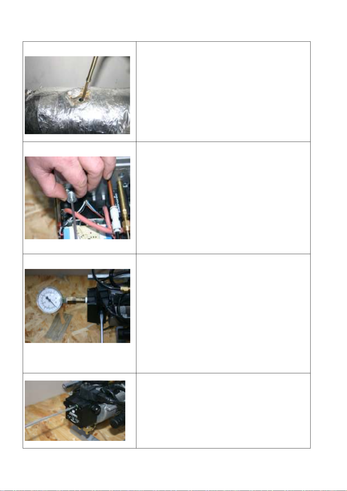
TEMPRATEC C1
Step 6:
Step 7
Step 8
Upon burner startup – Insert measuring probe from the
emissions device into the measuring opening on the
exhaust gas tube and observe exhaust gas values.
As required, open or close air valve for combustion air in
relation to measured data.
Please remember
Using the Allen key provided, turn the cheesehead bolt at
the top left of the burner housing.
Loosen counter-wheel and turn Allen key, as required:
to the right: reduce air volume
to the left: increase air volume.
Important:
Tighten down counter-wheel.
Pressure setting on the Suntec oil pump is realized parallel
to setting of the output and measurement data.
This is done on the right side of the upper edge of the oil
pump with a large flat-blade screwdriver.
:
Please remember:
Observe pressure gauge on screwed-in manometer.
Turn to the right – Raise pump pressure and burner
output. ( see table on p. 9)
Turn to the left – Reduce pump pressure and burner
output. (see table on p. 9)
Step 9:
After setting the measurement data and burner output,
switch off burner, screw out manometer, screw in plug and
put burner into service.
- 21 -
Page 22
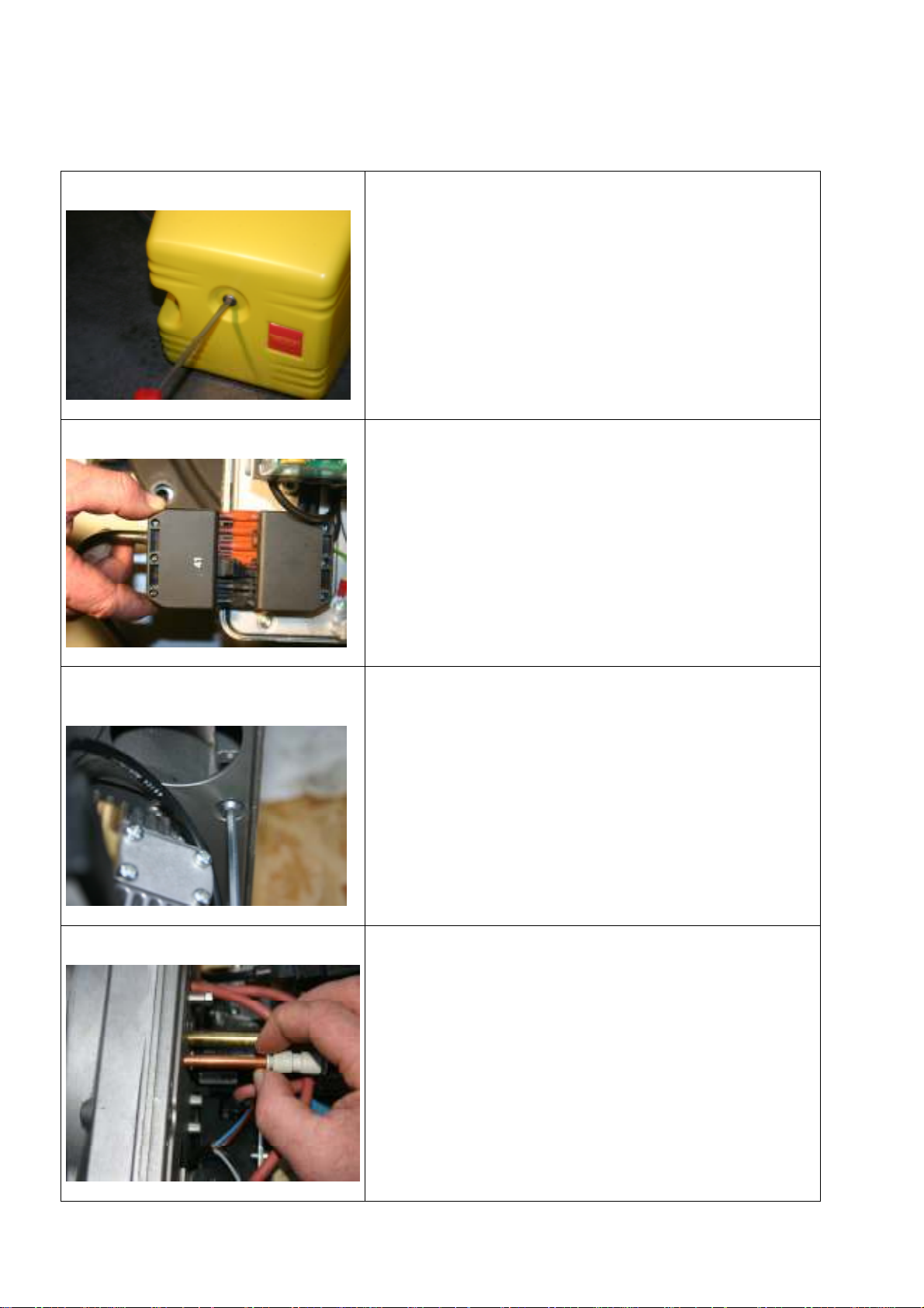
20. Service Instructions
Step 1:
Step 2
TEMPRATEC C1
Use screwdriver to loosen the fastening bolt on the C1
burner hood and remove burner hood.
Please remember:
Use large screwdriver.
Remove electrical connection from boiler at burner Euro
socket and switch off boiler system.
Step 3:
Step 4
Loosen four cheesehead bolts on burner housing and
remove housing lid.
Please remember:
Attach burner housing at the upper right.
Compressor air supply coupling: Press ring towards the
back and pull off.
- 22 -
Page 23
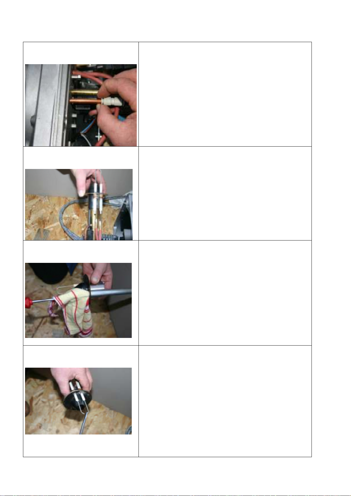
TEMPRATEC C1
Step 5
Step 6:
Pull ignition cable off of the ignition electrodes.
Pull off air cover.
Step 7
Step 8
Clean residues off air cover using a brass wire brush.
Clean flicker detector tubes.
Clean ignition electrodes and reset to 3 mm gap.
- 23 -
Page 24
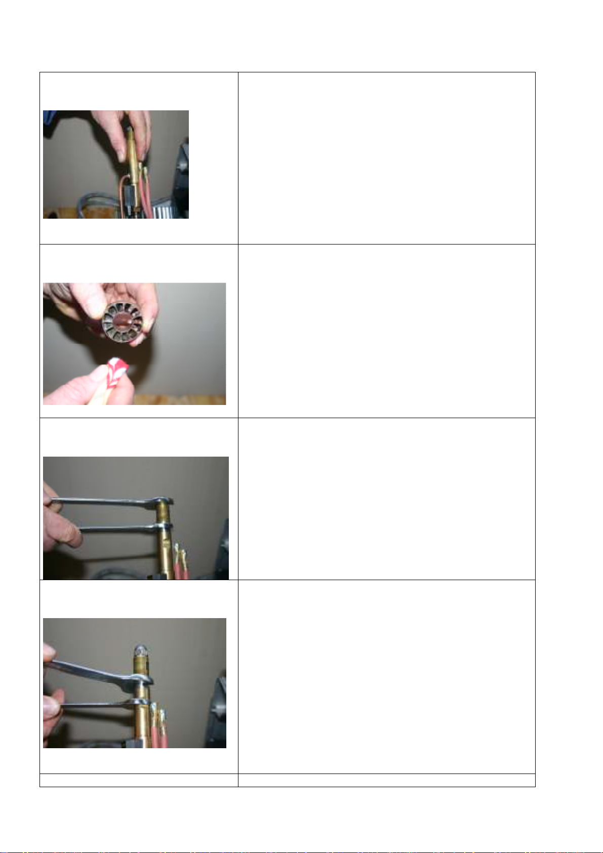
TEMPRATEC C1
Step 9
Step 10
Pull off compressed air mantle forwards.
Check gasket rings in mantle for damage.
Clean turbulator with cloth.
Step 11
Step 12
Replace oil nozzle.
Please remember:
Size 16 open-end spanner, whereby a size 16 open-end
wrench is used to restrain the nozzle holder to keep it from
turning.
Replace or clean throttle filter.
Please remember:
Size 16 open-end spanner on throttle body, whereby a
size 16 open-end wrench is used to restrain the throttle
extension to keep it from turning.
Step 13
- 24 -
Page 25
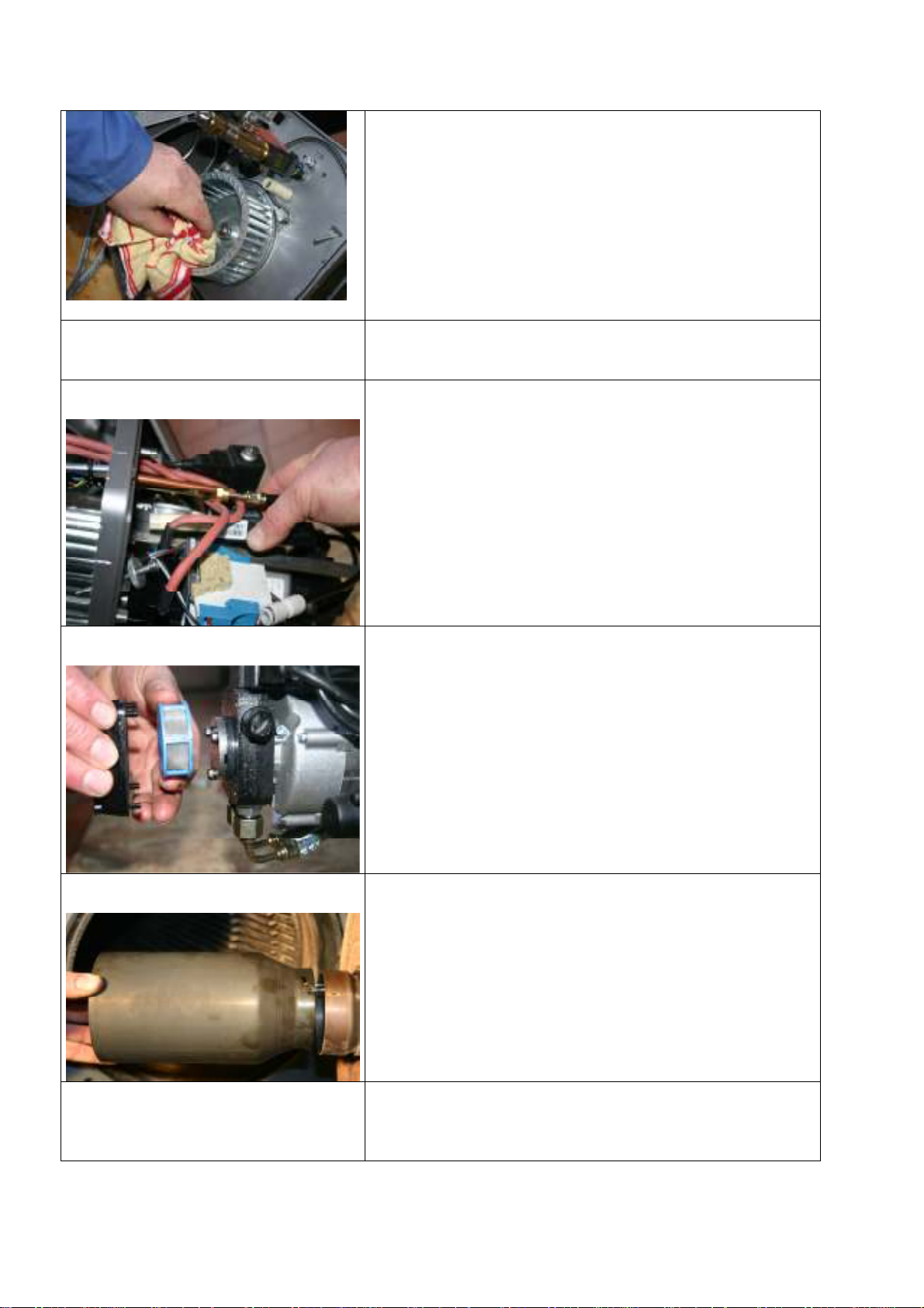
Step 14
Step 15
TEMPRATEC C1
Clean blower turbine with cloth.
Bolt on blower lid. (see figure, Step 3.)
Pull off photocell and clean it.
Step 16
Step 17
Oil pump:
Loosen four cheesehead bolts on the oil pump lid. Clean
pump sieve and inner housing.
Open boiler door, pull off flame tube with bayonet mount
and clean it.
Step 18
Check all cheesehead bolts and tighten them.
Connect electrical supply line at burner Euro plug and put
into service.
- 25 -
 Loading...