

Page 1
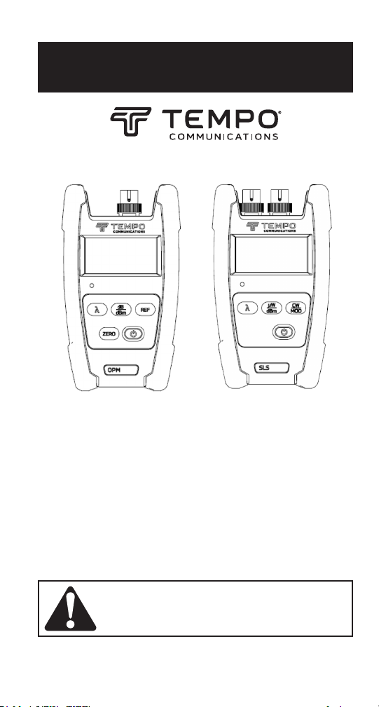
INSTRUCTION MANUAL
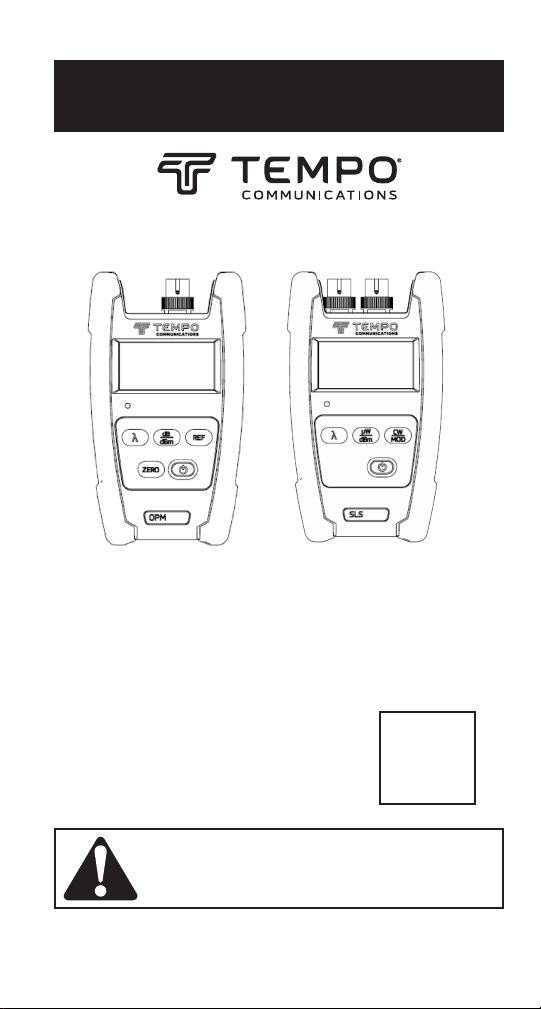
OPM510 • OPM520
Fiber Optic Power Meter
SLS520 • SLS530 • SLS535 • SLS536
Laser Source
SLS525
LED Source
English......1
Spanish...22
French.....43
German...64
Read and understand all of the instructions and
safety information in this manual before operating or servicing this tool.
Register this product at www.TempoCom.com
55501380 REV0 © 2022 Tempo Communications Inc. 01/22
Page 2

Table of Contents
Description .............................................................................................3
Safety .....................................................................................................4
Purpose of This Manual ..........................................................................4
Important Safety Information ............................................................ 5–7
Introduction ....................................................................................... 8–9
Model Designations ..........................................................................8
Unpacking and Inspection ................................................................9
Specications ................................................................................ 10–11
OPM ................................................................................................10
SLS .................................................................................................11
General Information ....................................................................... 12–13
Auto-Shutoff Feature ......................................................................12
Battery Installation or Replacement ...............................................13
Snap-On Connector (SOC) Interface ...............................................13
Operation ....................................................................................... 14–15
OPM ................................................................................................14
SLS .................................................................................................15
Applications .....................................................................................16-20
One Test Jumper Method: Connector Loss ...............................16-17
Two Test Jumper Method: Link Loss ........................................18-20
Warranty ...............................................................................................21
KEEP THIS MANUAL
2
Page 3

OPM510 • OPM520 • SLS520 • SLS525 • SLS530 • SLS535 • SLS536
Description
The Tempo Communications berTOOLS™ instruments are handheld
ber optic tools designed to measure optical power levels and link loss
on multi-mode and single-mode ber optic cabling networks.
• The OPM510 power meter measures optical power at 850 nm, 1300
nm, 1310 nm, 1490nm, 1550nm and 1625 nm between a power range of
+10 to -65dBm. The OPM510 is supplied standard with a SC bulkhead
adapter with LC, ST and FC adapters optionally available.
• The OPM520 power meter measures optical power at 850 nm, 1300
nm, 1310 nm, 1490nm, 1550nm and 1625 nm between a power range of
+27 to -50dBm. The OPM520 is supplied standard with a SC bulkhead
adapter with LC, ST and FC adapters optionally available.
• The SLS520 Laser source provides a light source at 1310nm and
1550nm to measure insertion loss on singlemode ber optic cabling.
The SLS520 is supplied standard with a SC bulkhead adapter with LC,
ST and FC adapters optionally available.
• The SLS525 LED source provides a light source at 850nm and 1300nm
to measure insertion loss on multimode ber optic cabling. The SLS525
is supplied standard with a SC bulkhead adapter with LC, ST and FC
adapters optionally available. The modal launch is not controlled.
• The SLS530 Laser source provides a light source at 1310nm, 1490nm
and 1550nm to measure insertion loss on singlemode ber optic
cabling. The SLS530 is supplied standard with a SC bulkhead adapter
with LC, ST and FC adapters optionally available.
• The SLS535 Laser source provides a light source at 1310nm, 1550nm
and 1625nm to measure insertion loss on singlemode ber optic
cabling. The SLS535 is supplied standard with a SC bulkhead adapter
with LC, ST and FC adapters optionally available.
• The SLS536 Laser source provides a light source at 1310nm, 1550nm
and 1650nm to measure insertion loss on singlemode ber optic
cabling. The SLS536 is supplied standard with a SC bulkhead adapter
with LC, ST and FC adapters optionally available.
3
Page 4

Safety
Safety is essential in the use and maintenance of Tempo
Communications tools and equipment. This instruction manual and
any markings on the tool provide information for avoiding hazards
and unsafe practices related to the use of this tool. Observe all of the
safety information provided.
Purpose of This Manual
This instruction manual is intended to familiarize all personnel with
the safe operation and maintenance procedures for the Tempo
Communications OPM510, OPM520, SLS520, SLS525, SLS530, SLS535
and SLS536 berTOOLS instruments.
4
Page 5
OPM510 • OPM520 • SLS520 • SLS525 • SLS530 • SLS535 • SLS536
Important Safety Information
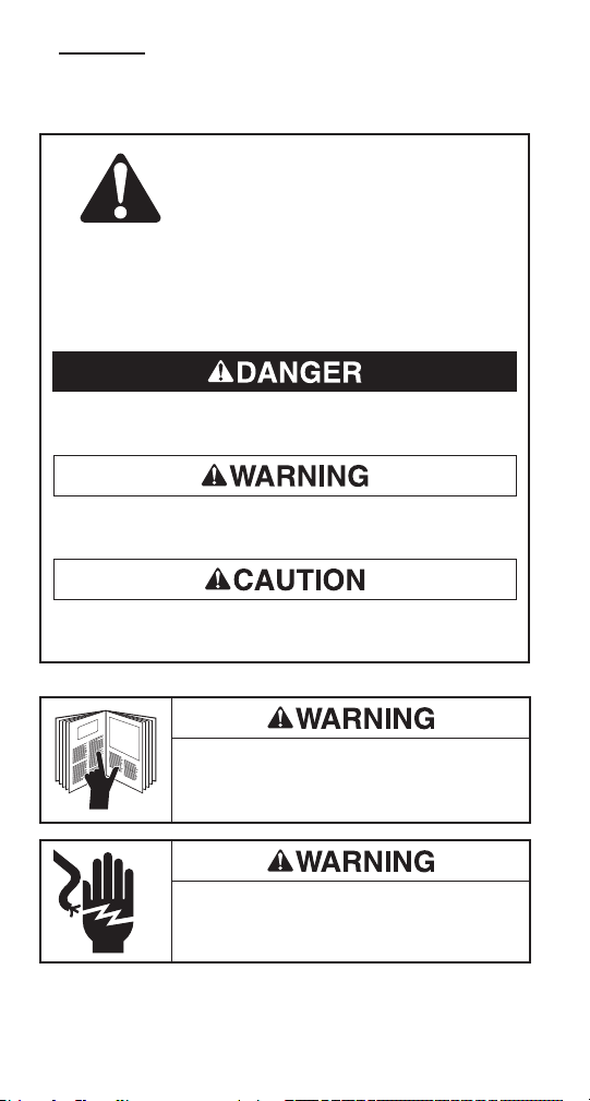
SAFETY ALERT SYMBOL
This symbol is used to call your attention to hazards or unsafe
practices which could result in an injury or property damage. The
signal word, dened below, indicates the severity of the hazard.
The message after the signal word provides information for
preventing or avoiding the hazard.
Immediate hazards which, if not avoided, WILL result in severe
injury or death.
Hazards which, if not avoided, COULD result in severe injury or
death.
Hazards or unsafe practices which, if not avoided, MAY result in
injury or property damage.
Read and understand this material before operating or servicing this equipment. Failure to understand how to safely operate this tool could result
in an accident causing serious injury or death.
Electric shock hazard:
Contact with live circuits could result in severe
injury or death.
5
Page 6
Important Safety Information
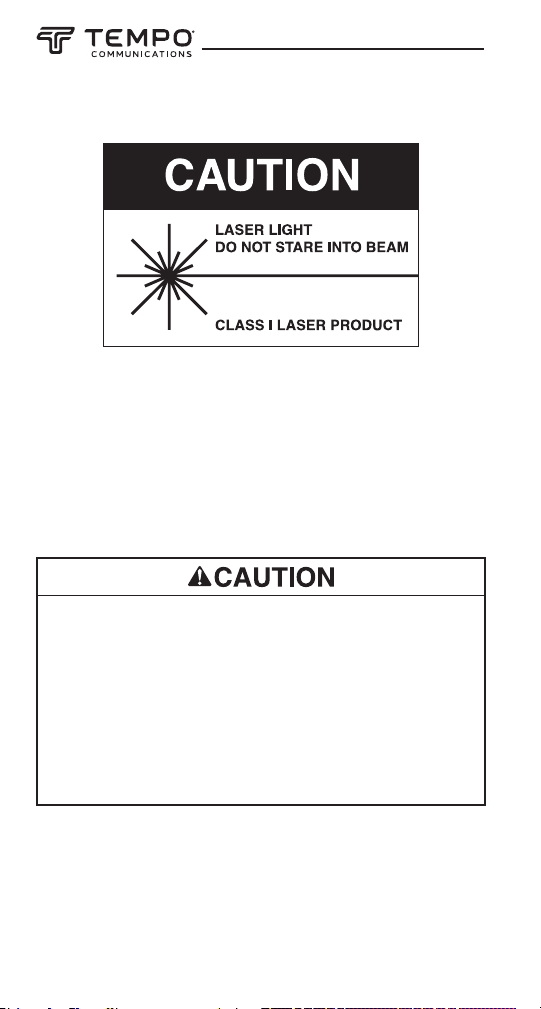
The SLS520, SLS530, SLLS535 and SLS5336 instruments are a laser
device conforming to the requirements of CDRH, CFR 1040. While there
is no potential for eye damage due to unaided direct exposure, users
should always avoid looking directly into the output port. The use of
optical viewing instruments, such as microscopes, magniers, etc.,
should always be avoided. The use of such devices around active bers
can focus an intense beam of light energy onto the retina of the eye,
which can result in permanent damage.
Laser hazard:
• When performing measurements on ber optic systems, avoid eye
exposure to any open-ended bers, optical connectors, optical
interfaces, or other sources because they may be connected to
active laser transmitters.
• Do not look into the optical port when a source is turned on.
• Avoid looking at the free end of a test ber, i.e., the end not con-
nected to the instrument. If possible, direct the free end toward a
non-reflective surface.
Failure to observe these precautions may result in injury.
6
Page 7

OPM510 • OPM520 • SLS520 • SLS525 • SLS530 • SLS535 • SLS536
Important Safety Information
Electric shock hazard:
• Do not insert batteries with the polarity reversed.
• Do not open the case of the unit for any reason. It contains no userserviceable parts.
• Use this unit for the manufacturer’s intended purpose only, as
described in this manual. Any other use can impair the protection
provided by the unit.
Failure to observe these precautions may result in injury and may
damage the unit.
Instrument damage hazard:
• Do not leave the unit in direct sunlight or near direct sources of
heat.
• Protect the unit from strong impacts or shock.
• Do not immerse the unit in water or store in areas with high
humidity.
• When necessary, clean the case, front panel, and rubber cover with
a damp cloth. Do not use abrasives, harsh chemicals, or solvents.
• Replace the interface dust cap(s) when the unit is not in use.
• Store the unit and interface adapters in a cool, dry, and clean place.
Failure to observe these precautions may result in injury and may
damage the unit.
7
Page 8

Introduction
Model Designations
The berTOOLS instruments incorporate different types of interfaces
and must be used with the compatible adapters.
berTOOLS Individual Instruments
OPM510 InGaAs Optical Power Meter
OPM520 InGaAs Optical Power Meter with high power
measurement range
SLS520 1310/1550nm Laser Source with SC connector
SLS525 850/1300nm LED Source with SC connector
SLS530 1310/1490/1550nm Laser Source with SC connector
SLS535 1310/1550/1625nm Laser Source with SC connector
SLS536 1310/1550/1650nm Laser Source with SC connector
berTOOLS Instruments Kits
SM DUAL KIT OPM510 & SLS520
SM DUAL KIT HP OPM520 & SLS520
MM DUAL KIT OPM510 & SLS525
SM T PON KIT OPM510 & SLS530
SM T 1625 KIT OPM510 & SLS535
SM T 1650 KIT OPM510 & SLS536
SM T PON KIT HP OPM520 & SLS530
SM T 1625 KIT HP OPM520 & SLS535
SM T 1650 KIT HP OPM520 & SLS536
SMMMKIT-T OPM510, SLS520 & SLS525
SMMMKIT-M OPM520, SLS520 & SLS525
Tempo Communications OPM Adapters
SC-OPM SC Adapter
LC-OPM LC Adapter
FC-OPM FC Adapter
ST-OPM ST Adapter
SCAPC-OPM SC/APC Adapter
8
Page 9

OPM510 • OPM520 • SLS520 • SLS525 • SLS530 • SLS535 • SLS536
Do not discard this product or throw away!
For recycling information, go to www.TempoCom.com.
Tempo Communications SLS Adapters
SC-Source SC/UPC Adapter
LC-Source LC/UPC Adapter
FC-Source FC/UPC Adapter
ST-Source ST/UPC Adapter
Tempo Communications Accessories
CC-1 Carry Case, Single Instrument
PS-100 External Power Supply
CC-2-3 Carry Case, Dual & Triple Instrument
Unpacking and Inspection
All berTOOLS instruments have been carefully inspected before
shipment. When received, the shipping carton should contain the items
listed below:
• 1 berTOOLS instrument
• 1 Soft Carry Case
• 1 Quick Reference Card
Please account for and inspect each item while unpacking and preparing the instrument for use.
If the instrument received is damaged, contact Tempo
Communications.
Keep the shipping carton in case re-shipment is required for any
reason.
Do not discard this product or throw away!
For recycling information, go to www.TempoCom.com.
All specications are nominal and may change as design improvements occur.
Tempo Communications Inc. shall not be liable for damages resulting from
misapplication or misuse of its products.
berTOOLS is a trademark of Tempo Communications Inc.
9
Page 10

Specications
OPM
MODEL OPM510 OPM520
Cal. Wavelength 850, 1300, 1310, 1490, 1550,1625nm
Measure range -65 ~ +10
Detector type InGaAs
Accuracy
Linearity
Resolution (dB) 0.01dB
Functions
Connector Type SC (Interchangeable LC, FC and ST)
Fiber Type Singlemode & Multimode
Battery Life > 100 hours
Power Supply
Operating Temperature -10°C ~ 50°C
Storage Temperature -20°C ~ 70°C
Relative Humidity 0 to 95% (non-condensing)
Weight 0.68lbs (310g)
Dimensions (H × W × T) 6.1 × 3.5 × 1.3” (155 × 88 × 33mm)
IP Rating IP54
Vibration 5Hz to 150Hz, Amplitude = 0.15mm
Shock Peak acceleration 25g at a pulse duration of 6ms
Compliance CE, FCC
+/-0.5dB (+10 to -3dBm)
+/-0.1dB (-3 to -50dBm)
+/-0.5dB (-50 to -65dBm)
9V Alkaline or 1000mAh Lithium Battery / 9V AC
(1) The lower limit of 850nm measurement is -60 dBm for OPM510.
Specications subject to change without notice.
(1)
dBm -50 ~ +27dBm
±0.25 dB
(±0.5dB@850nm)
+/-0.5dB +27 to -3dBm
+/-0.1dB -3 to -50dBm
µW/dBm/dB(REF)/ MOD tone detection
270Hz, 1kHz, 2kHz
adapter
10
Page 11

OPM510 • OPM520 • SLS520 • SLS525 • SLS530 • SLS535 • SLS536
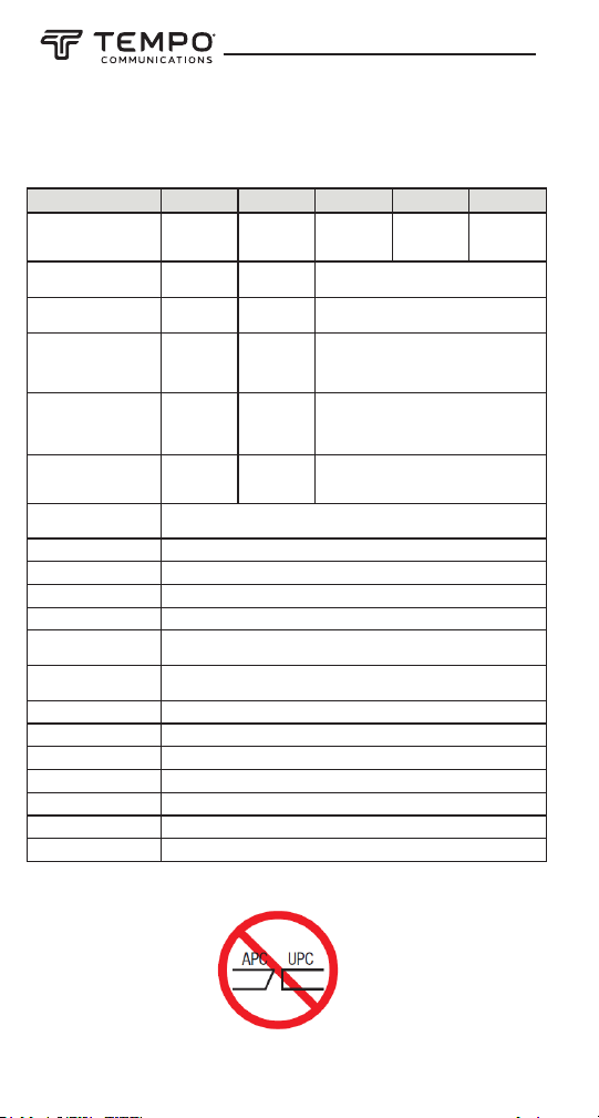
Model
SLS520
SLS525
SLS530
Wavelength (±20nm)
1310/1550
850/1300 1310/1550/1625
1310/1550/1650
1310/1490/1550
Range of Use
Singlemode
Multimode
Singlemode
Emitter Type FP LED
FP
Spectral Width
≤ 5 nm
+/-40 nm
≤ 5 nm
SLS535
SLS536
Specications
SLS
MODEL SLS520 SLS525 SLS530 SLS535 SLS536
Center Wavelength 1310/1550nm 850/1300nm
-1dBm
±0.05
Multimode
(62.5/125)
≤ 71nm
(850nm),
≤ 160nm
(1300nm)
-20dBm/
-21dBm
±0.05
dB/15min;
±0.15dB/8hr
Fiber Type Singlemode
Emitter Type FP LED FP
Spectrum Width ≤ 5 nm
Output Power
(Max/Min)
Output Power Stability
Modulation Frequency 270Hz, 1kHz, 2kHz
Display LCD
Battery Life 60 hours
Connector Type SC/PC (Interchangeable LC, ST, SC)
Power Supply 9V Alkaline or 1000mAh Lithium Battery / 9V AC adapter
Operating Temperature -10 to +50°C
Storage Temperature -20 to +70°C
Relative Humidity 0 to 95% (non-condensing)
Weight 0.71 lbs (300g)
Dimensions (H × W × T) 6.1 × 3.5 × 1.3” (155 × 88 × 33mm)
IP Rating IP54
Vibration 5Hz to 150Hz, Amplitude = 0.15mm
Shock Peak acceleration 25g at a pulse duration of 6ms
Compliance CE, FCC, 21 CFR 1040.10 (laser)
0dBm/
dB/15min;
±0.10dB/8hr
1310/
1490/
1550nm
1310/
1550/
1625nm
Singlemode
≤ 5 nm
0dBm/-1dBm
±0.05 dB/15min;
±0.10dB/8hr
1310/
1550/
1650nm
Specications subject to change without notice.
11
Page 12

General Information
This section provides general instructions on how to use the berTOOLS instruments.
If circumstances require that the instruments be serviced and
maintained in-house, contact Tempo Communications for technical
assistance.
Battery
The OPM510, OPM520, SLS520, SLS525, SLS530, SLS535 and SLS536
instruments are powered by one 9V alkaline battery or one 9V Lithium
battery.
The optional external power supply can be used to power the OPM and
SLS rather than an alkaline battery. The external power supply is not
used to charge any rechargeable battery that may be installed in the
OPM or SLS.
Do not attempt to charge alkaline batteries with the external power
supply.
When the battery power is low the low battery indicator will be displayed on the LCD.
Auto Power Off.
The instrument will automatically turn off if there are no keypad pushes
for approximately ve minutes.
To deactivate the auto power off hold the [On/Off] when turning on until
“AUTO OFF” is displayed on LCD. To reactivate the auto power off hold
the [On/Off] button until “AUTO OFF” is no longer displayed.
12
Page 13

OPM510 • OPM520 • SLS520 • SLS525 • SLS530 • SLS535 • SLS536
Battery Installation or Replacement
To replace the batteries, follow these steps:
1. Turn instrument off.
2. Remove battery cover by sliding down.
3. Install new battery to the wire leads observing correct polarity.
Connector Interface
All berTOOLS OPM and SLS units utilize a screw on adapter for SC,
LC, FC and ST congurations. The OPM and SLS instrument bulkheads
are unique in that the adapters for the OPM are different from the SLS.
Do not attempt to use a OPM adapter on a SLS or vice versa. Please
consult the accessories section of this instruction manual for adapter
part numbers.
13
Page 14

Cleaning the OPM and SLS Interfaces
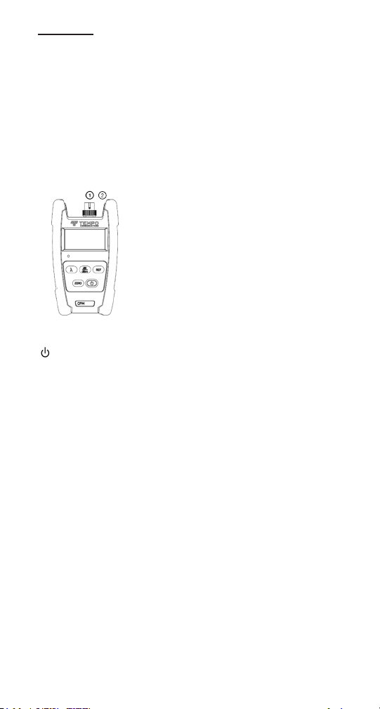
①① Fiber Optic Input
OPM510 & OPM520 is available with SC fiber optic connector
(Interchangeable LC/ST/FC).
②② Ext. AC Power Jack
OPM510 & OPM520 can be operated with an External Power Adapter 9V
DC@250mA.
Make sure that the instrument is powered off. Do not look into the
output of any SLS port. Unscrew the OPM adapter and use a clean lint
fee wipe to clean the exposed OPM detector window. Always use a new
2.5mm cleaning swab to clean the SLS bulkhead.
OPM Operations
External Connector Instruction
1. Fiber Optic Input
OPM510 & OPM520 is available with SC ber
optic connector (Interchangeable LC/ST/FC).
2. Ext. AC Power Jack
OPM510 & OPM520 can be operated with an
External Power Adapter 9V DC@250mA.
Keypad Functions
: Push the power button to turn the OPM on or off. The default
setting will turn the OPM off after ve minutes of inactivity. Hold the
power button for two seconds to place the OPM into a constant on
mode. Holding the power button again for twoseconds will revert to the
auto off mode.
dB/dBm: Press this key to toggle between dB and dBm.
Zero: Press the Zero key to zero the OPM with the input port protected
from ambient light. A message of “SUCC” will be displayed upon successful zeroing. If an “ERR” message appears check that the input port
was in fact covered properly and repeat the zeroing procedure. Zeroing
the OPM will remove the effects of any dark current inherent to the
detector diode.
REF: Press the REF key to set a 0dB reference.
: Press this key to select the desired wavelength. The current
wavelength will be displayed on LCD.
14
Page 15
OPM510 • OPM520 • SLS520 • SLS525 • SLS530 • SLS535 • SLS536
①① Fiber Optic Input
OPM510 & OPM520 is available with SC fiber optic connector
(Interchangeable LC/ST/FC).
②② Ext. AC Power Jack
OPM510 & OPM520 can be operated with an External Power Adapter 9V
DC@250mA.
SLS Operations
External Connector Instruction
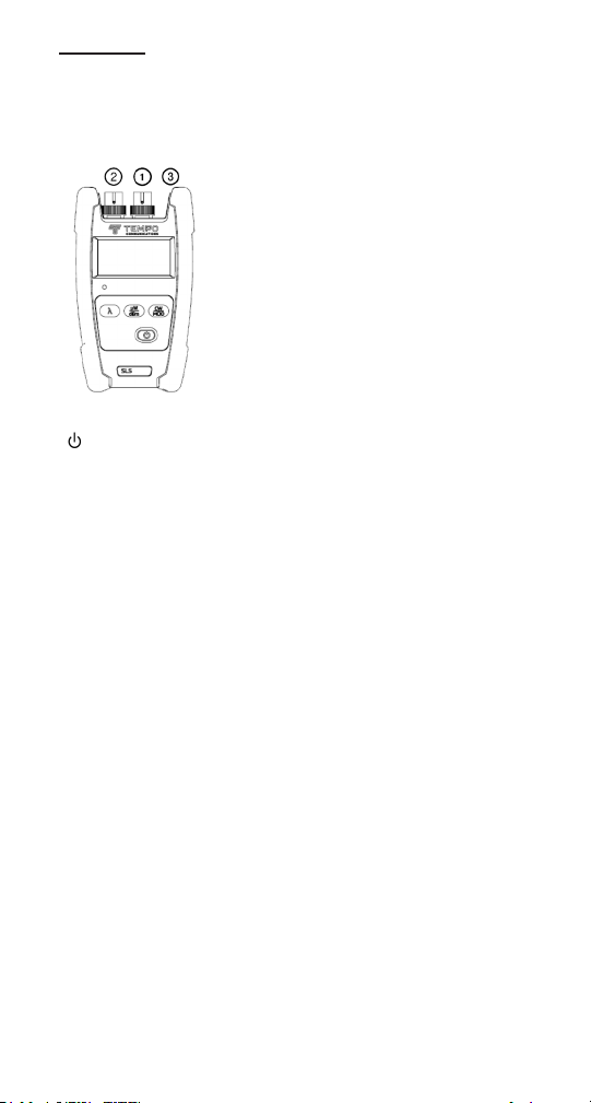
1. Fiber Optic Output
SLS supplied with SC/PC ber optic connector
(intechangeable LC/FC/ST). This is a flat polished
connector; do not connect angle polished connectors
to the bulkhead.
2. Ext. AC Power Jack
SLS can be operated with an External Power Adapter
9V DC@250mA.
Keypad Functions
: Power on or off the instrument. With the default setting, the SLS
will conserve battery life by automatically turning itself off if no key has
been pressed for approximately 5 minutes.
μW/Bm: Press this key to switch the display mode from absolute power
(dBm) to microwatt(μW). The current optical power will be displayed
on LCD.
CW/Mod: Press this key to switch the output of SLS from CW to the
desired modulation frequency.
: Press this key to select the desired wavelength. The current wave-
length will be displayed on LCD.
15
Page 16
Applications
①① Fiber Optic Input
OPM510 & OPM520 is available with SC fiber optic connector
(Interchangeable LC/ST/FC).
②② Ext. AC Power Jack
OPM510 & OPM520 can be operated with an External Power Adapter 9V
DC@250mA.
The following applications for the berTOOLS instruments are
described in this manual:
• Connector/cable insertion loss measurements
• Link loss measurements
One Test Jumper Method: Connector Loss
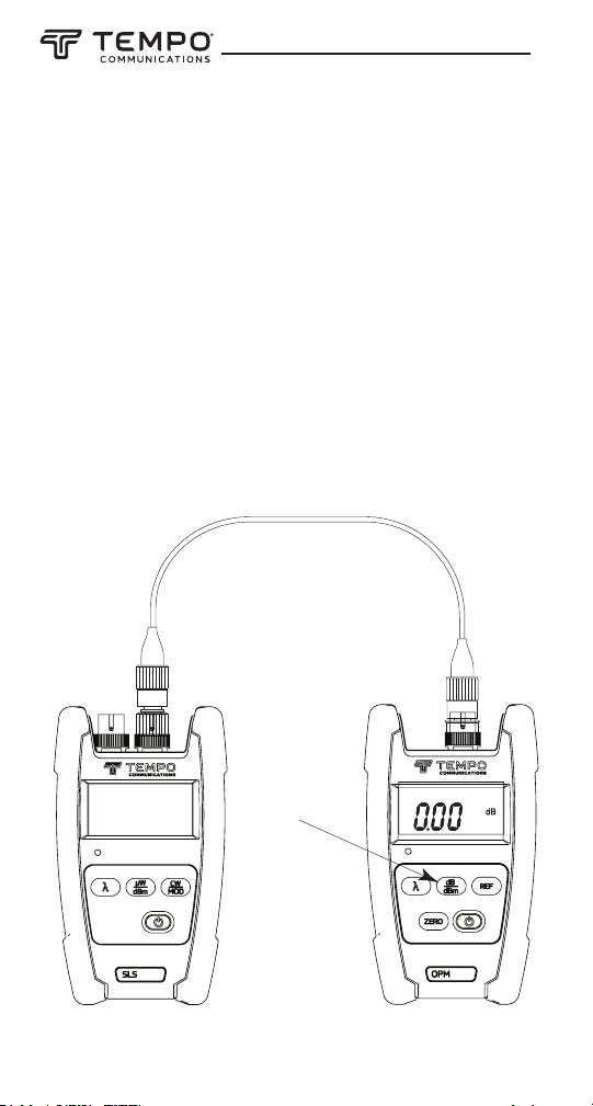
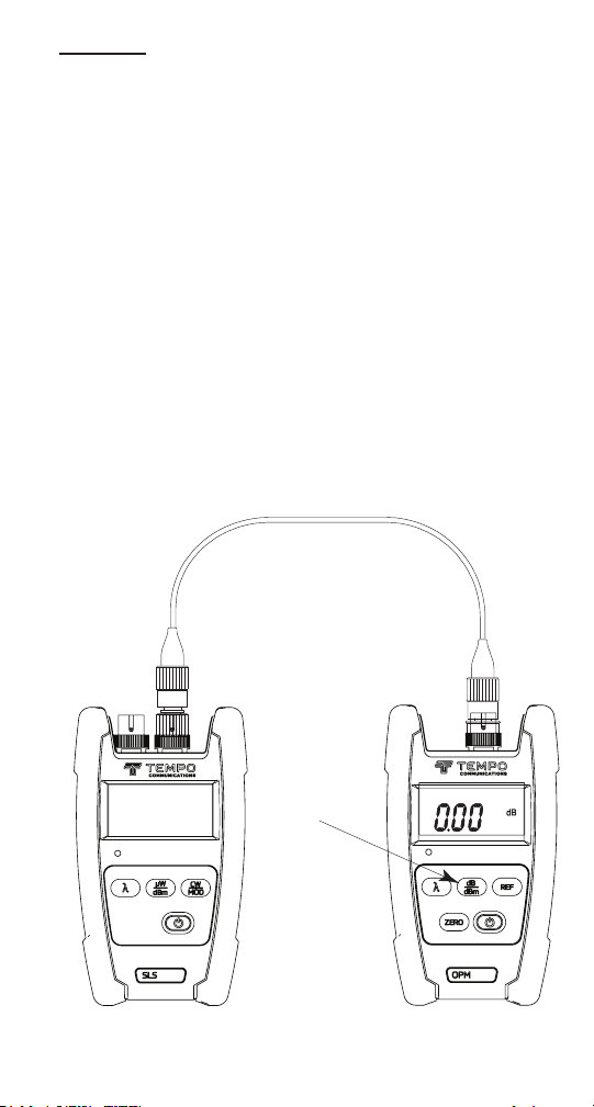
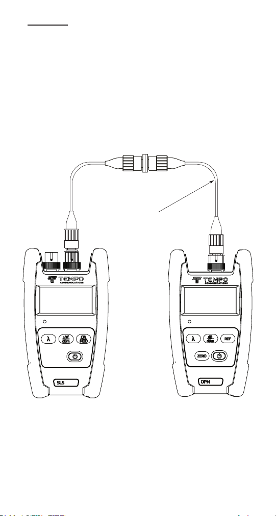
1. Connect an appropriate light source to the optical power meter
using a suitable reference cable with a length of about 2 to 3
meters (6 to 10 feet).
2. Ensure that the light source is in continuous wave (CW) output
mode. Set the optical power meter to the appropriate wavelength
(using the [ ] key) and to dBm units (using the [dB/dBm] key).
3. To store the reference level, press the [dB/dBm] key on the optical
power meter until the display reads 0.00 dB. See below.
Press the
[dB/dBm]
key to set the
0 dB reference
Source
16
Power meter
Page 17
OPM510 • OPM520 • SLS520 • SLS525 • SLS530 • SLS535 • SLS536
One Test Jumper Method: Connector Loss (cont’d)
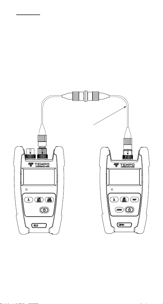
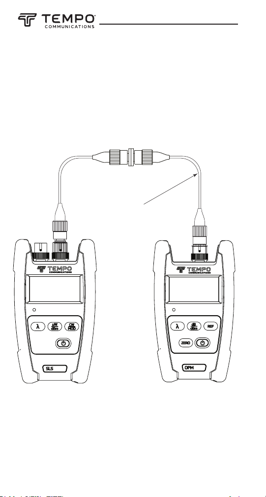
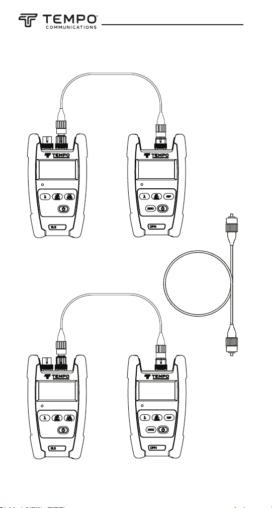
4. Disconnect the reference cable end from the optical power
meter and insert the cable to be tested using an appropriate
mating adapter. The optical power meter reads the connector/
cable loss in dB.
Cable/connector
under test
Source
Power meter
17
Page 18
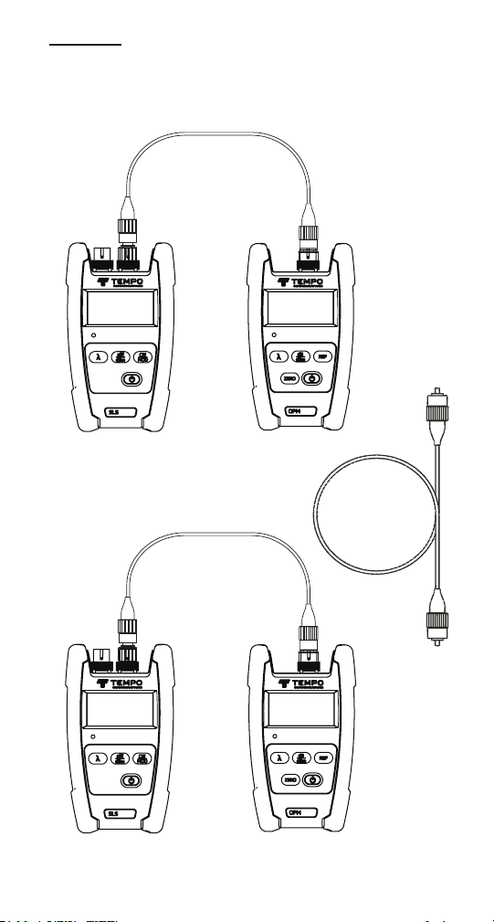
Two Test Jumper Method: Link Loss
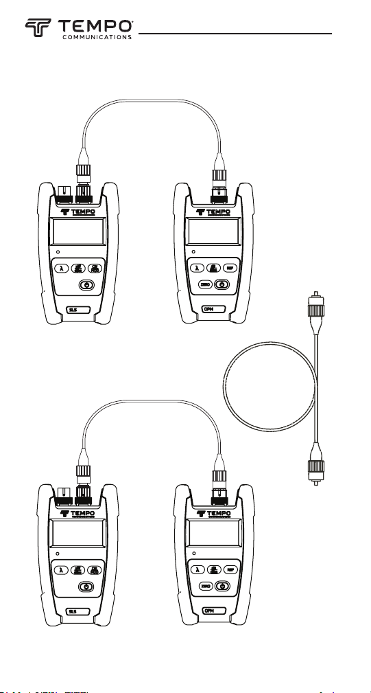
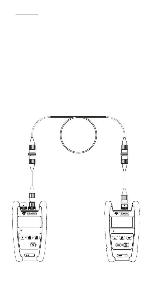
Test jumper 1
P1
Source Power meter
Test jumper 2
A
Cable
plant
Source Power meter
18
B
P2
Page 19
OPM510 • OPM520 • SLS520 • SLS525 • SLS530 • SLS535 • SLS536
Two Test Jumper Method: Link Loss (cont’d)
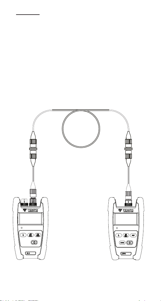
1. If a complete test set (light source and optical power meter) is
available at each end, it is advisable to test the output power of
the sources and the condition of the test jumpers before
commencing measurement of the link.
Connect each source and optical power meter with a test jumper,
as shown above. The sources should be set to continuous wave
(CW) output mode. The power meters should be set to the correct
wavelength and to dBm measurement units. Note the P1 and P2
dBm readings. For example, a SLS520 1310 NM laser source
should read approximately -1dBm on the optical power meter.
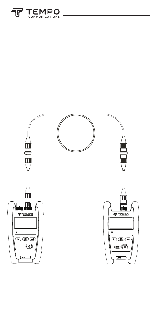
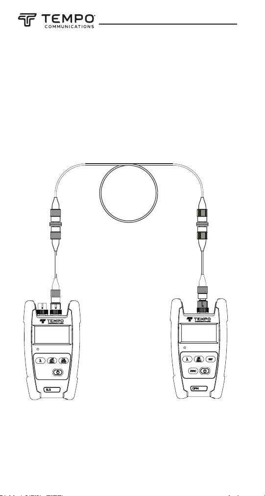
Cable
plant
A B
FORWARD LOSS (dB) = P1 – P3
Test
jumper 1
Test
jumper 2
P3
Source Power meter
19
Page 20
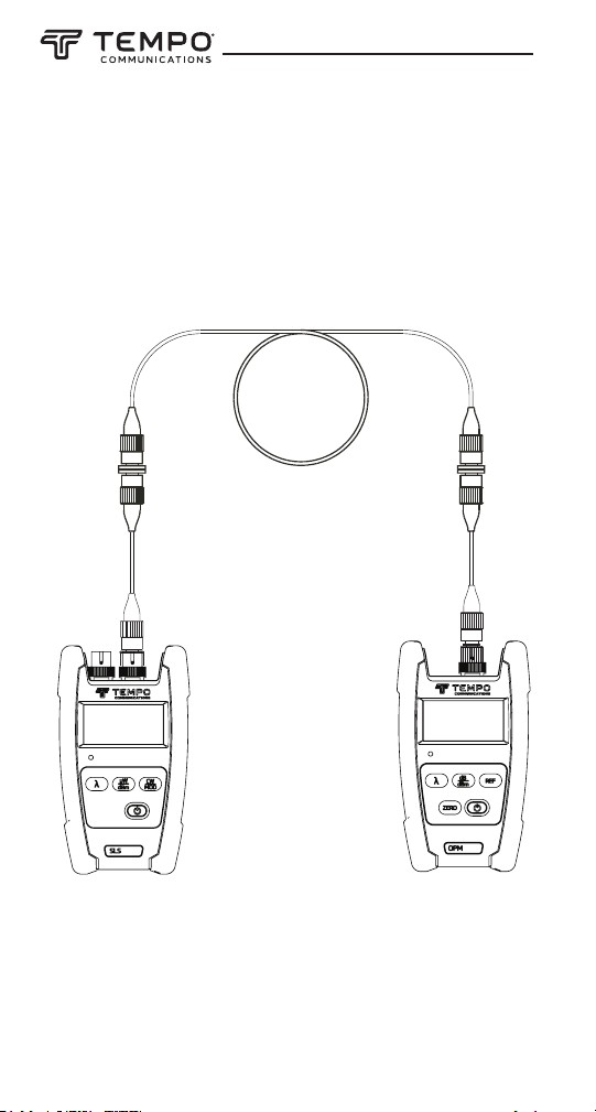
Two Test Jumper Method: Link Loss (cont’d)
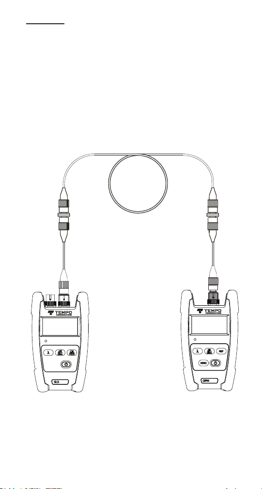
Source
P4
Power meter
Test
jumper 1
Test
jumper 2
A B
Cable
plant
REVERSE LOSS (dB) = P2 – P4
2. Connect a light source and optical power meter to the respective
patch panel ports using the test jumpers, as shown on the left.
3. Using the formula shown above, take the dBm reading on the
optical power meter (P3) and the nominal source output value,
corresponding to the light source in use.
Note: Make sure the optical power meter supports the wavelength
of the light source in use.
4. It is advisable to measure the loss in both directions. Reverse
the source and optical power meter connections, as shown above.
Calculate the reverse loss using the formula shown above.
5. Report both forward and reverse loss values.
20
Page 21

OPM510 • OPM520 • SLS520 • SLS525 • SLS530 • SLS535 • SLS536
Limited Warranty
Tempo Communications Inc. warrants to the original purchaser of these
goods for use that these products will be free from defects in workmanship and material for three years, excepting normal wear and abuse.
For all Test instrument repairs, you must rst request a Return
Authorization Number by contacting our Customer Service department
at:
Toll free in the US and Canada 800-642-2155
Telephone +1 760 510-0558.
Facsimile +1 760 598-9263.
This number must be clearly marked on the shipping label. Ship units
Freight Prepaid to: Tempo Repair Center, 1390 Aspen Way, Vista, CA
92081 USA.
Mark all packages: Attention: TEST INSTRUMENT REPAIR.
For items not covered under warranty (such as dropped, abused, etc.)
repair cost quote available upon request.
Note: Prior to returning any test instrument, please check to make sure
batteries are fully charged.
Tempo Communications
1390 Aspen Way • Vista, CA 92081 • USA
800-642-2155
Tempo Europe Ltd. • Brecon House • William Brown Close
Cwmbran • NP44 3AB • UK • Tel: +44 1633 927 050
www.TempoCom.com
21
Page 22
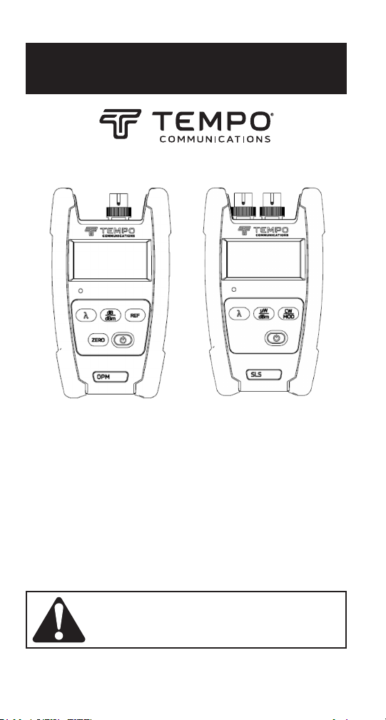
MANUAL DE INSTRUCCIONES
OPM510 • OPM520
Medidor de potencia de bra óptica
SLS520 • SLS530 • SLS535 • SLS536
Fuente láser
SLS525
Fuente LED
Lea y comprenda todas las instrucciones y la
información de seguridad de este manual antes
de operar o dar servicio a esta herramienta.
Registre este producto en www.TempoCom.com
55501380 REV0 © 2022 Tempo Communications Inc. 01/22
Page 23

OPM510 • OPM520 • SLS520 • SLS525 • SLS530 • SLS535 • SLS536
Índice
Descripción ....................................................................................................24
Seguridad .......................................................................................................25
Propósito de este manual .............................................................................25
Información importante de seguridad .................................................... 26-28
Introducción ...................................................................................................29
Designaciones de modelo ......................................................................29
Desembalaje e inspección ......................................................................30
Especicaciones ............................................................................................31
OPM .........................................................................................................31
SLS ..........................................................................................................32
Información general ......................................................................................33
Función de apagado automático ...........................................................33
Instalación o remplazo de la batería ......................................................34
Interfaz de conector a presión (SOC) .....................................................34
Operación .......................................................................................................35
OPM .........................................................................................................35
SLS ..........................................................................................................36
Aplicaciones ..................................................................................................37
Método de un puente de prueba: pérdida de conector .................... 37-38
Método de dos puentes de prueba: pérdida de enlace .................... 39-41
Garantía .........................................................................................................42
CONSERVE ESTE MANUAL
23
Page 24

Descripción
Los instrumentos Tempo Communications berTOOLS™ son herramientas
de bra óptica portátiles diseñados para medir los niveles de potencia
óptica y pérdida de enlace en redes de cableado de bra óptica multimodo
y monomodo.
• El medidor de potencia OPM510 mide la potencia óptica a 850nm,
1,300nm, 1,310nm, 1,490nm, 1,550nm y 1,625nm entre un rango
de potencia de +10 a -65 dBm. El OPM510 se suministra de manera
estándar con un adaptador SC con adaptadores LC, ST y FC disponibles
opcionalmente.
• El medidor de potencia OPM520 mide la potencia óptica a 850nm,
1,300nm, 1,310nm, 1,490nm, 1,550nm y 1,625nm entre un rango
de potencia de +27 a -50 dBm. El OPM520 se suministra de manera
estándar con un adaptador SC, con adaptadores LC, ST y FC disponibles
opcionalmente.
• La fuente láser SLS520 proporciona una fuente de luz a 1,310nm
y 1,550nm para medir la pérdida de inserción en cableado de bra
óptica monomodo. El SLS520 se suministra de manera estándar con un
adaptador SC, con adaptadores LC, ST y FC disponibles opcionalmente.
• La fuente LED SLS525 proporciona una fuente de luz a 850nm y
1,300nm para medir la pérdida de inserción en cableado de bra
óptica multimodo. El SLS525 se suministra de manera estándar con un
adaptador SC con adaptadores LC, ST y FC disponibles opcionalmente. El
lanzamiento modal no está controlado.
• La fuente láser SLS530 proporciona una fuente de luz a 1,310nm,
1,490nm y 1,550nm para medir la pérdida de inserción en cableado
de bra óptica monomodo. El SLS530 se suministra con un adaptador
estándar SC con adaptadores LC, ST y FC disponibles opcionalmente.
• La fuente láser SLS535 proporciona una fuente de luz a 1,310nm,
1,550nm y 1,625nm para medir la pérdida de inserción en cableado
de bra óptica monomodo. El SLS535 se suministra con un adaptador
estándar SC con adaptadores LC, ST y FC disponibles opcionalmente.
• La fuente láser SLS536 proporciona una fuente de luz a 1,310nm,
1,550nm y 1,650nm para medir la pérdida de inserción en cableado
de bra óptica monomodo. El SLS536 se suministra con un adaptador
estándar SC con adaptadores LC, ST y FC disponibles opcionalmente.
24
Page 25

OPM510 • OPM520 • SLS520 • SLS525 • SLS530 • SLS535 • SLS536
Seguridad
La seguridad es esencial en el uso y mantenimiento de las herramientas
y los equipos de Tempo Communications. Este manual de instrucciones
y cualquier marca en la herramienta proporcionan información para evitar
peligros y prácticas inseguras relacionadas con el uso de esta herramienta.
Observe toda la información de seguridad proporcionada.
Propósito de este manual
Este manual de instrucciones está diseñado para familiarizar a todo el
personal con los procedimientos seguros de operación y mantenimiento de
los instrumentos berTOOLS OPM510, OPM520, SLS520, SLS525, SLS530,
SLS535 y SLS536 de Tempo Communications.
25
Page 26
Información importante de seguridad
SÍMBOLO DE ALERTA
DESEGURIDAD
Este símbolo se utiliza para llamar su atención a los peligros o las
prácticas inseguras que podrían provocar lesiones o daños a la
propiedad. La palabra de advertencia, denida a continuación, indica
la gravedad del peligro. El mensaje después de la palabra de advertencia proporciona información para prevenir o evitar el peligro.
Peligros inmediatos que, si no se evitan, PROVOCARÁN lesiones
graves o la muerte.
Peligros que, si no se evitan, PODRÍAN provocar lesiones graves o
la muerte.
Peligros o prácticas inseguras que, si no se evitan, PUEDEN provocar
lesiones o daños a la propiedad.
Lea y comprenda este material antes de utilizar o
darle servicio a este equipo. Si no se entiende cómo
operar de forma segura esta herramienta, podría
producirse un accidente causando lesiones graves
o la muerte.
Peligro de descarga eléctrica:
El contacto con circuitos activos podría provocar
lesiones graves o la muerte.
26
Page 27
OPM510 • OPM520 • SLS520 • SLS525 • SLS530 • SLS535 • SLS536
Información importante de seguridad
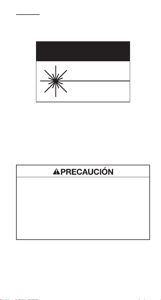
PRECAUCUÓN
LUZ LÁSER
NO MIRE FIJAMENTE EL HAZ
PRODUCTO LÁSER CLASE I
Los instrumentos SLS520, SLS530, SLS535 y SLS536 son dispositivos
láser que cumplen los requisitos de CDRH, CFR 1040. Si bien no existe
posibilidad de daños oculares debido a una exposición directa sin ayuda,
los usuarios siempre deben evitar mirar directamente al puerto de salida.
Siempre debe evitarse el uso de instrumentos de visualización óptica,
como microscopios, lupas, etc. El uso de estos dispositivos alrededor de
bras activas puede enfocar un haz intenso de energía lumínica sobre la
retina del ojo, lo que puede provocar daños permanentes.
Peligro de láser:
• Al realizar mediciones en sistemas de bra óptica, evite la
exposición de los ojos a cualquier bra abierta, conectores ópticos,
interfaces ópticas u otras fuentes abiertas, ya que pueden estar
conectadas a transmisores de láser activos.
• No mire al puerto óptico cuando esté encendida una fuente.
• Evite mirar el extremo libre de una bra de prueba, es decir, el
extremo no conectado al instrumento. Si es posible, dirija el
extremo libre hacia una supercie no reflejante.
Si no se siguen estas precauciones, podrían producirse lesiones.
27
Page 28

Información importante de seguridad
Peligro de descarga eléctrica:
• No inserte baterías con la polaridad invertida.
• No abra la carcasa de la unidad por ningún motivo. Contiene piezas
que el usuario no puede reparar.
• Utilice esta unidad únicamente para el propósito previsto del fab-
ricante, tal como se describe en este manual. Cualquier otro uso
puede afectar a la protección que brinda la unidad.
Si no se siguen estas precauciones, podrían producirse lesiones y
podría dañar la unidad.
Peligro de daños al instrumento:
• No deje la unidad en exposición a luz solar directa ni cerca de
fuentes directas de calor.
• Proteja la unidad de impactos fuertes o choques.
• No sumerja la unidad en agua ni la almacene en zonas de
alta humedad.
• Cuando sea necesario, limpie la caja, el panel frontal y la cubierta
de hule con un paño húmedo. No utilice abrasivos, productos
químicos corrosivos ni disolventes.
• Sustituya la tapa(s) anti polvo de la interfaz cuando la unidad no
esté en uso.
• Guarde la unidad y los adaptadores de interfaz en un lugar fresco,
seco y limpio.
Si no se siguen estas precauciones, podrían producirse lesiones y
podría dañar la unidad.
28
Page 29

OPM510 • OPM520 • SLS520 • SLS525 • SLS530 • SLS535 • SLS536
Introducción
Designaciones de modelo
Los instrumentos berTOOLS incorporan distintos tipos de interfaces y
deben utilizarse con los adaptadores compatibles.
Herramientas individuales berTOOLS
OPM510 Medidor de potencia óptica InGaAs
OPM520 Medidor de potencia óptica InGaAs
con rango de medición de alta potencia
SLS520 Fuente láser de 1,310/1,550nm con conector SC
SLS525 Fuente LED de 850/1,300nm con conector SC
SLS530 Fuente láser de 1,310/1,490/1,550nm con conector SC
SLS535 Fuente láser de 1,310/1,550/1,625nm con conector SC
SLS536 Fuente láser de 1,310/1,550/1,650nm con conector SC
Kits de instrumentos berTOOLS
KIT DUAL SM OPM510 y SLS520
KIT DUAL SM HP OPM520 y SLS520
KIT DUAL MM OPM510 y SLS525
KIT SM T PON OPM510 y SLS530
KIT SM T 1625 OPM510 y SLS535
KIT SM T 1650 OPM510 y SLS536
KIT SM T PON HP OPM520 y SLS530
KIT SM T 1625 HP OPM520 y SLS535
KIT SM T 1650 HP OPM520 y SLS536
SMMMKIT-T OPM510, SLS520 y SLS525
SMMMKIT-M OPM520, SLS520 y SLS525
Adaptadores para OPM Tempo Communications
SC-OPM Adaptador SC
LC-OPM Adaptador LC
FC-OPM Adaptador FC
ST-OPM Adaptador ST
SCAPC-OPM Adaptador SC/APC
29
Page 30

Adaptadores para SLS Tempo Communications
Do not discard this product or throw away!
For recycling information, go to www.TempoCom.com.
Fuente-SC Adaptador SC/UPC
Fuente-LC Adaptador LC/UPC
Fuente-FC Adaptador FC/UPC
Fuente-ST Adaptador ST/UPC
Accesorios Tempo Communications
CC-1 Caja de transporte, para un solo instrumento
PS-100 Fuente de alimentación externa
CC-2-3 Caja de transporte, instrumento doble y triple
Desembalaje e inspección
Todos los instrumentos berTOOLS se inspeccionan cuidadosamente
antes de su envío. Cuando se reciba, la caja de envío debe contener los
elementos enumerados a continuación:
• 1 instrumento berTOOLS
• 1 Estuche de transporte suave
• 1 Tarjeta de referencia rápida
Revise que esté presente e inspeccione cada elemento mientras los
desempaca y prepara el instrumento para su uso.
Si el instrumento recibido está dañado, póngase en contacto con
Tempo Communications.
Conserve la caja de envío en caso de que sea necesario volver a enviarla
por cualquier motivo.
¡No deseche este producto ni lo tire!
Para obtener información sobre reciclaje, visite
www.TempoCom.com.
Todas las especicaciones son nominales y pueden cambiar a medida que se
producen mejoras en el diseño. Tempo Communications Inc. no será responsable
de los daños como resultado de la aplicación incorrecta o el uso indebido de sus
productos.
berTOOLS es una marca comercial de Tempo Communications Inc.
30
Page 31

OPM510 • OPM520 • SLS520 • SLS525 • SLS530 • SLS535 • SLS536
Especicaciones
OPM
MODELO OPM510 OPM520
Longitud Longitud de onda 850, 1,300, 1,310, 1,490, 1,550, 1,625nm
Rango de medición De -65 a +10
Tipo de detector InGaAs
Precisión
Linealidad
Resolución 0.01dB
Funciones
Tipo de conector SC (LC, FC y ST intercambiables)
Tipo de bra Monomodo y multimodo
Vida útil de la batería > 100 horas
Fuente de alimentación
Temperatura de
funcionamiento
Temperatura de
almacenamiento
Humedad relativa 0 a 95% (sin condensación)
Peso 300g (0.68lb)
Dimensiones (Al × An × P) 155 × 88 × 33 mm (6.1 x 3.5 x 1.3”)
Clasicación IP IP54
Vibración 5Hz a 150Hz, amplitud = 0.15mm
Choque Aceleración máxima 25g a una duración de pulso de 6ms
Cumple con CE, FCC
±0.5dB (+10 a -3dBm)
±0.1dB (-3 a -50dBm)
±0.5dB (-50 a -65dBm)
Pila alcalina de 9 V o batería de litio de 1,000mAh /
(1) El límite inferior de la medición de 850nm es de -60dBm para OPM510.
Especicaciones sujetas a cambios sin previo aviso.
(1)
dBm De -50 a +27dBm
±0.25 dB
(±0.5dB a 850nm)
±0.5dB +27 a -3dBm
±0.1dB -3 a -50dBm
µW/dBm/dB(REF)/ TONO MOD DETECT
270 Hz, 1 kHz, 2 kHz
adaptador de CA de 9V
-10°C ~ 50°C
-20°C ~ 70°C
31
Page 32
Model
SLS520
SLS525
SLS530
Wavelength (±20nm)
1310/1550
850/1300 1310/1550/1625
1310/1550/1650
1310/1490/1550
Range of Use
Singlemode
Multimode
Singlemode
Emitter Type FP LED
FP
Spectral Width
≤ 5 nm
+/-40 nm
≤ 5 nm
SLS535
SLS536
Especicaciones
SLS
MODELO SLS520 SLS525 SLS530 SLS535 SLS536
Longitud de onda central 1,310/1,550nm 850/1,300nm
±0.05
Multimodo
(62.5/125)
≤ 71nm
(850nm),
≤ 160nm
(1300nm)
-20dBm/
-21dBm
±0.05
dB/15min;
±0.15dB/8h
Rango de uso Monomodo
Tipo de emisor FP LED FP
Ancho espectral ≤5nm
Potencia de salida típica/
mínima
Estabilidad de potencia
de salida
Frecuencia de
modulación
Pantalla LCD
Vida útil de la batería 60horas
Tipo de conector SC/PC (LC, ST, SC intercambiable)
Fuente de alimentación Pila alcalina de 9 V o batería de litio de 1,000mAh / adaptador de CA de 9V
Temperatura de
funcionamiento
Temperatura de
almacenamiento
Humedad relativa 0 a 95% (sin condensación)
Peso 300g (0.71lb)
Dimensiones (Al × An × P) 155 × 89 × 33 mm (6.1 x 3.5 x 1.3”)
Clasicación IP IP54
Vibración 5Hz a 150Hz, amplitud = 0.15mm
Choque Aceleración máxima 25g a una duración de pulso de 6ms
Cumple con CE, FCC, 21 CFR 1040.10 (láser)
0dBm/
-1dBm
dB/15min;
±0.10dB/8h
1,310/
1,490/
1,550nm
270Hz, 1kHz, 2kHz
De -10 a +50°C
De -20 a +70°C
1,310/
1,550/
1,625nm
Monomodo
≤5nm
0dBm/-1dBm
±0.05dB/15min;
±0.10dB/8h
1,310/
1,550/
1,650nm
Especicaciones sujetas a cambios sin previo aviso.
32
Page 33

OPM510 • OPM520 • SLS520 • SLS525 • SLS530 • SLS535 • SLS536
Información general
Esta sección proporciona instrucciones generales sobre cómo utilizar los
instrumentos berTOOLS.
Si las circunstancias requieren que los instrumentos reciban
mantenimiento y reparaciones internamente, póngase en contacto con
Tempo Communications para obtener asistencia técnica.
Batería
Los instrumentos OPM510, OPM520, SLS520, SLS525, SLS530, SLS535 y
SLS536 están equipados con una batería alcalina de 9V o una batería de
litio de 9V.
La fuente de alimentación externa opcional se puede utilizar para alimentar
el OPM y sls en lugar de una batería alcalina. La fuente de alimentación
externa no se utiliza para cargar ninguna batería recargable que pueda
instalarse en el OPM o SLS.
No intente cargar baterías alcalinas con la fuente de alimentación externa.
Cuando la batería esté baja, el indicador de batería baja se mostrará en la
pantalla LCD.
Apagado automático.
El instrumento se apagará automáticamente si no se oprime ninguna tecla
durante aproximadamente cinco minutos.
Para desactivar el apagado automático, mantenga pulsado el botón [On/
Off] cuando se encienda hasta que aparezca “AUTO OFF” en la pantalla
LCD. Para volver a activar el apagado automático, mantenga pulsado el
botón [On/Off] hasta que ya no aparezca la opción “AUTO OFF”.
33
Page 34

Instalación o remplazo de la batería
Para sustituir las baterías, siga estos pasos:
1. Apague el instrumento.
2. Retire la tapa de la batería deslizándola hacia abajo.
3. Instale la batería nueva en los conectores de los cables vericando la
polaridad correcta.
Interfaz de conector
Todas las unidades OPM y SLS de berTOOLS utilizan un adaptador
atornillable para conguraciones SC, LC, FC y ST. Los cabezales de los
instrumentos OPM y SLS son únicos ya que los adaptadores para el OPM
son diferentes de los SLS. No intente utilizar un adaptador OPM en un
SLS o viceversa. Consulte la sección de accesorios de este manual de
instrucciones para conocer los números de pieza del adaptador.
34
Page 35
OPM510 • OPM520 • SLS520 • SLS525 • SLS530 • SLS535 • SLS536
①① Fiber Optic Input
OPM510 & OPM520 is available with SC fiber optic connector
(Interchangeable LC/ST/FC).
②② Ext. AC Power Jack
OPM510 & OPM520 can be operated with an External Power Adapter 9V
DC@250mA.
Limpieza de las interfaces OPM y SLS
Asegúrese que el instrumento esté apagado. No mire la salida de ningún
puerto SLS. Desenrosque el adaptador OPM y utilice un paño libre de
pelusa para limpiar la ventana expuesta del detector OPM. Utilice siempre
un hisopo de limpieza nuevo de 2.5 mm para limpiar el adaptador SLS.
Funcionamiento del OPM
Instrucciones para el conector externo
1. Entrada de bra óptica
OPM510 y OPM520 están disponibles con conector
2. Toma externa de corriente CA
El OPM510 y el OPM520 se pueden utilizar
de bra óptica SC (LC/ST/FC intercambiable).
con un adaptador de alimentación externa de
9V CC a 250mA.
Funciones de los botones
: Presione el botón de encendido para encender o apagar el OPM. En
la conguración predeterminada el OPM se apagará después de cinco
minutos de inactividad. Mantenga presionado el botón de encendido
durante dos segundos para poner el OPM en el modo de encendido
constante. Si mantiene pulsado el botón de encendido de nuevo durante
dos segundos, volverá al modo de apagado automático.
dB/dBm: Presione este botón para alternar entre dB y dBm.
Zero: Presione el botón «Zero» con el puerto de entrada protegido de la luz
ambiente para poner a cero el OPM. Verá el mensaje «SUCC» en pantalla
cuando la puesta a cero se haya completado. Si recibiera el mensaje
«ERR», compruebe que el puerto de entrada esté cubierto correctamente
y repita el procedimiento de la puesta a cero. Poner a cero el OPM
eliminará los efectos de cualquier corriente de oscuridad inherente al
diodo detector.
REF: Presione el botón «REF» para establecer una referencia de 0dB
: Presione este botón para seleccionar la longitud de onda deseada. La
longitud de onda actual se mostrará en la pantalla LCD.
35
Page 36

Operaciones SLS
①① Fiber Optic Input
OPM510 & OPM520 is available with SC fiber optic connector
(Interchangeable LC/ST/FC).
②② Ext. AC Power Jack
OPM510 & OPM520 can be operated with an External Power Adapter 9V
DC@250mA.
Instrucciones de conector externo
1. Salida de bra óptica
El SLS se suministra con conector de bra óptica SC/PC
2. Toma externa de corriente CA
La SLS puede utilizarse con un adaptador de
9V CC a 250mA.
(LC/FC/ST intercambiable). Este es un conector pulido
plano; no conecte conectores pulidos con ángulos al
adaptador.
alimentación externa
Funciones del teclado
: Encienda o apague el instrumento. Con la conguración predeterminada, la
SLS conservará la duración de la batería apagándose automáticamente si no se ha
pulsado ninguna tecla durante aproximadamente 5 minutos.
μW/Bm: Pulse esta tecla para cambiar el modo de visualización de potencia absoluta
(dBm) a microvatios(μW). La potencia óptica actual se mostrará en la pantalla LCD.
CW/Mod: Pulse esta tecla para cambiar la salida de SLS de CW a la frecuencia de
modulación deseada.
: Pulse esta tecla para seleccionar la longitud de onda deseada. La longitud de
onda actual se mostrará en la pantalla LCD.
36
Page 37
OPM510 • OPM520 • SLS520 • SLS525 • SLS530 • SLS535 • SLS536
①① Fiber Optic Input
OPM510 & OPM520 is available with SC fiber optic connector
(Interchangeable LC/ST/FC).
②② Ext. AC Power Jack
OPM510 & OPM520 can be operated with an External Power Adapter 9V
DC@250mA.
Aplicaciones
En este manual se describen las siguientes aplicaciones para los
instrumentos berTOOLS:
• Mediciones de pérdida de inserción de cableado/conector
• Mediciones de pérdida de enlace
Método de un puente de prueba: Pérdida de conector
1. Conecte una fuente de luz adecuada al medidor de potencia óptica
utilizando un cable de referencia adecuado con una longitud de
aproximadamente 2 a 3 metros (6 a 10 pies).
2. Asegúrese que la fuente de luz esté en modo de salida de onda
continua (CW). Ajuste el medidor de potencia óptica a la longitud de
onda adecuada (utilizando la tecla [
la tecla [dB/dBm] ).
3. Para almacenar el nivel de referencia, pulse la tecla [dB/dBm] en el
medidor de potencia óptica hasta que la pantalla muestre 0.00dB.
Consulte a continuación.
] ) y a unidades dBm (utilizando
Fuente
Pulse la tecla
[dB/dBm] para
establecer
la referencia
de 0 dB
Medidor de potencia
37
Page 38
Método de un puente de prueba: pérdida de conector
(cont.)
4. Desconecte el extremo del cable de referencia del medidor de
potencia óptica e inserte el cable que se va a probar utilizando un
adaptador de acoplamiento adecuado. El medidor de potencia óptica
lee la pérdida de conector/cable en dB.
Conector de cable
bajo prueba
Fuente
38
Medidor de potencia
Page 39
OPM510 • OPM520 • SLS520 • SLS525 • SLS530 • SLS535 • SLS536
Método de dos puentes de prueba: pérdida de enlace
Puente de prueba 1
P1
Fuente Medidor de potencia
Planta
de cable
Puente de prueba 2
A
P2
Fuente Medidor de potencia
B
39
Page 40
Método de dos puentes de prueba: pérdida de enlace
(cont.)
1. Si se dispone de un conjunto de pruebas completo (fuente de luz y
medidor de potencia óptica) en cada extremo, se recomienda probar la
potencia de salida de las fuentes y el estado de los puentes de prueba
antes de comenzar la medición del enlace.
Conecte cada fuente y medidor de potencia óptica con un puente de
prueba, como se muestra arriba. Las fuentes deben congurarse en
modo de salida de onda continua (CW). Los medidores de potencia
deben ajustarse a la longitud de onda correcta y a las unidades de
medición dBm. Anote las lecturas de dBm en P1 y P2. Por ejemplo,
una fuente láser SLS520 de 1,310 NM debería leer aproximadamente
-1dBm en el medidor de potencia óptica.
Planta
de cable
A B
PÉRDIDAS HACIA
DELANTE (dB) = P1 – P3
Puente de
prueba 1
Puente de
prueba 2
P3
Fuente Medidor de potencia
40
Page 41
OPM510 • OPM520 • SLS520 • SLS525 • SLS530 • SLS535 • SLS536
Método de dos puentes de prueba: pérdida de enlace
(cont.)
2. Conecte una fuente de luz y un medidor de potencia óptica a los
puertos respectivos del panel de conexiones utilizando los puentes de
prueba, como se muestra a la izquierda.
3. Utilizando la fórmula anterior, tome la lectura dBm en el medidor
de potencia óptica (P3) y el valor de salida nominal de la fuente,
correspondiente a la fuente de luz utilizada.
Nota: Asegúrese que el medidor de potencia óptica admite la longitud
de onda de la fuente de luz utilizada.
Planta
de cable
A B
PÉRDIDAS HACIA
ATRÁS (dB) = P2 – P4
Puente de
prueba 1
Puente de
prueba 2
P4
Fuente
4. Es aconsejable medir la pérdida en ambas direcciones. Invierta
la fuente y las conexiones del medidor de potencia óptica, como
se muestra arriba. Calcule la pérdida inversa utilizando la fórmula
mostrada anteriormente.
5. Reporte ambos valores de pérdida, de ida y de regreso.
Medidor de potencia
41
Page 42

Garantía limitada
Tempo Communications Inc. garantiza al comprador original de estos
bienes que el uso de estos productos estará libre de defectos de fabricación
y material durante tres años, excepto por el desgaste y abuso normales.
Para todas las reparaciones de instrumentos de prueba, primero debe
solicitar un número de autorización de devolución poniéndose en contacto
con nuestro Departamento de Atención al Cliente en el:
número gratuito en EE. UU. y Canadá 800-642-2155
Teléfono +1 760 510-0558.
Fax +1 760 598-9263.
Este número debe estar claramente marcado en la etiqueta de envío. Envíe
las unidades con flete prepagado a: Tempo Repair Center, 1390 Aspen Way,
Vista, CA 92081 USA.
Marque todos los paquetes: Atención: REPARACIÓN DE INSTRUMENTO DE
PRUEBA (TEST INSTRUMENT REPAIR).
Para elementos que no estén cubiertos en la garantía (por ejemplo,
caídas, abuso, etc.), la cotización del costo de reparación está disponible
previa solicitud.
Nota: Antes de devolver cualquier instrumento de prueba, por favor
compruebe que las baterías estén totalmente cargadas.
TempoCommunications
1390 Aspen Way • Vista, CA 92081 • USA
800-642-2155 • Una empresa ISO 9001
Tempo Europe Ltd. • Brecon House • William Brown Close
Cwmbran • NP44 3AB • UK • Tel: +44 1633 927 050
www.TempoCom.com
Page 43
MODE D’EMPLOI
OPM510 • OPM520
Wattmètre à bre optique
SLS520 • SLS530 • SLS535 • SLS536
Source laser
SLS525
Source LED
Vous devez lire et comprendre toutes les instructions
et les consignes de sécurité de ce mode d’emploi
avant d’utiliser ou de réparer l’outil.
Enregistrez ce produit sur www.TempoCom.com
55501380 REV0 © 2022 Tempo Communications Inc. 01/22
Page 44

Table des matières
Description ...........................................................................................45
Sécurité ................................................................................................46
Objet de ce mode d’emploi .............................................................46
Consignes de sécurité importantes ...........................................47-49
Introduction ..........................................................................................50
Dénomination des modèles ............................................................50
Déballage et inspection ..................................................................51
Caractéristiques techniques ............................................................52-53
OPM ................................................................................................52
SLS .................................................................................................53
Informations générales .........................................................................54
Fonction d’arrêt automatique .........................................................54
Installation ou remplacement de la batterie ...................................55
Interface de connecteur clipsable (SOC) ........................................55
Fonctionnement ..............................................................................56-57
OPM ................................................................................................56
SLS .................................................................................................57
Applications ..........................................................................................58
Méthode à un cavalier de test : perte de connecteur .................58-59
Méthode à deux cavaliers de test : perte de lien........................60-62
Garantie ................................................................................................63
CONSERVEZ CE MODE D’EMPLOI
44
Page 45

OPM510 • OPM520 • SLS520 • SLS525 • SLS530 • SLS535 • SLS536
Description
Les instruments berTOOLS™ de Tempo Communications sont des
outils portatifs à bre optique conçus pour mesurer les niveaux de
puissance optique et la perte de liaison sur les réseaux de câbles à
bre optique multimode et monomode.
• Le wattmètre OPM510 mesure la puissance optique à 850, 1300,
1310, 1490, 1550 et 1625 nm dans une plage de puissance comprise
entre + 10 et - 65 dBm. L’OPM510 est livré avec un adaptateur traversant SC, et des adaptateurs LC, ST et FC sont disponibles en option.
• Le wattmètre optique OPM520 mesure la puissance optique à 850,
1300, 1310, 1490, 1550 et 1625 nm dans une plage de puissance
comprise entre + 27 et - 50 dBm. L’OPM520 est livré avec un adaptateur
traversant SC, et des adaptateurs LC, ST et FC sont disponibles en
option.
• La source laser SLS520 fournit une source lumineuse à 1310 et
1550 nm pour mesurer la perte d’insertion sur un câble à bre optique
monomode.
La SLS520 est livrée avec un adaptateur traversant SC, et des adapta-
teurs LC, ST et FC sont disponibles en option.
• La source LED SLS525 fournit une source lumineuse à 850 et 1
300 nm pour mesurer la perte d’insertion sur un câble à bre optique
multimode. La SLS525 est livrée avec un adaptateur traversant SC, et
des adaptateurs LC, ST et FC sont disponibles en option. Le lancement
modal n’est pas contrôlé.
• La source laser SLS530 fournit une source lumineuse à 1310, 1490 et
1550 nm pour mesurer la perte d’insertion sur un câble à bre optique
monomode. La SLS530 est livrée avec un adaptateur traversant SC, et
des adaptateurs LC, ST et FC sont disponibles en option.
• La source laser SLS535 fournit une source lumineuse à 1310, 1550 et
1625 nm pour mesurer la perte d’insertion sur un câble à bre optique
monomode. La SLS535 est livrée avec un adaptateur traversant SC, et
des adaptateurs LC, ST et FC sont disponibles en option.
• La source laser SLS536 fournit une source lumineuse à 1310, 1550
et 1650 nm pour mesurer la perte d’insertion sur un câble à bre
optique monomode. La SLS536 est livrée avec un adaptateur traversant
SC, et des adaptateurs LC, ST et FC sont disponibles en option.
45
Page 46

Sécurité
La sécurité est essentielle pour l’utilisation et la maintenance des
outils et équipements de Tempo Communications. Ce mode d’emploi
et tous les marquages présents sur l’outil fournissent des informations
pour utiliser cet outil en évitant les dangers et les pratiques dangereuses. Respectez toutes les consignes de sécurité indiquées.
Objet de ce mode d’emploi
Ce mode d’emploi est destiné à expliquer à tout personnel les procédures de fonctionnement et de maintenance en toute sécurité des
instruments berTOOLS OPM510, OPM520, SLS520, SLS525, SLS530,
SLS535 et SLS536 de Tempo Communications.
46
Page 47
OPM510 • OPM520 • SLS520 • SLS525 • SLS530 • SLS535 • SLS536
Consignes de sécurité importantes
SYMBOLE D’ALERTE DE
SÉCURITÉ
Ce symbole est utilisé pour attirer votre attention sur des dangers
ou des pratiques dangereuses qui pourraient entraîner des blessures ou des dégâts matériels. Les mots d’avertissement, tels que
dénis ci-dessous, renseignent sur le degré de gravité du danger.
Le message après le mot d’avertissement fournit des informations
an de prévenir ou d’éviter le danger.
Dangers immédiats qui, s’ils ne sont pas évités, ENTRAÎNERONT
des blessures graves voire mortelles.
Dangers qui, s’ils ne sont pas évités, POURRAIENT entraîner des
blessures graves voire mortelles.
Dangers ou pratiques dangereuses qui, s’ils ne sont pas évités,
PEUVENT entraîner des blessures ou des dégâts matériels.
Vous devez lire ces informations et bien les
comprendre avant d’utiliser l’équipement ou de le
réparer. L’utiliser de cet outil sans avoir compris
les consignes de sécurité peut entraîner un accident susceptible de causer des blessures graves
voire mortelles.
Risque de décharge électrique : Le contact avec
des circuits sous tension peut entraîner des blessures graves voire mortelles.
47
Page 48

Consignes de sécurité importantes
Les instruments SLS520, SLS530, SLLS535 et SLS5336 sont des
appareils laser conformes aux normes CFR 1040 du CDRH (Centre
américain des appareils et de la santé radiologique). Bien qu’il n’y ait
aucun risque de lésions oculaires suite à une exposition directe à l’œil
nu, les utilisateurs doivent toujours éviter de regarder directement
dans le port de sortie. L’utilisation d’instruments de vision optique,
tels que les microscopes, loupes, etc., doit être évitée. L’utilisation de
tels instruments autour de bres actives peut concentrer un faisceau
intense d’énergie lumineuse sur la rétine de l’œil, ce qui peut entraîner
des lésions permanentes.
Risques liés au laser :
• Lorsque vous effectuez des mesures sur des systèmes à bre
optique, évitez l’exposition des yeux à des bres ouvertes, des con-
necteurs optiques, des interfaces optiques ou d’autres sources, car
ils peuvent être connectés à des émetteurs laser actifs.
• Ne regardez pas dans le port optique lorsqu’une source est
allumée.
• Évitez de regarder l’extrémité libre d’une bre testée, c’est-à-
dire l’extrémité non connectée à l’instrument. Si possible, dirigez
l’extrémité libre vers une surface non réfléchissante.
Le non-respect de ces précautions peut entraîner des blessures.
48
Page 49

OPM510 • OPM520 • SLS520 • SLS525 • SLS530 • SLS535 • SLS536
Consignes de sécurité importantes
Risque de décharge électrique :
• Insérez toujours les batteries en respectant la polarité.
• N’ouvrez le boîtier de l’appareil sous aucun prétexte. Il contient des
pièces non réparables par l’utilisateur.
• Utilisez cet appareil uniquement aux ns prévues par le fabricant,
comme décrit dans ce mode d’emploi. Toute autre utilisation peut
altérer la protection fournie par l’unité.
Le non-respect de ces précautions peut entraîner des blessures et
endommager l’appareil.
Risque d’endommager l’instrument :
• Ne laissez pas l’appareil en plein soleil ou à proximité de sources
directes de chaleur.
• Protégez l’appareil des impacts et des chocs violents.
• N’immergez pas l’appareil dans l’eau et ne le stockez pas dans des
environnements très humides.
• Si nécessaire, nettoyez le boîtier, le panneau avant et le couvercle
en caoutchouc avec un chiffon humide. N’utilisez pas de produits
abrasifs ou solvants ni aucune substance chimique agressive.
• Lorsque vous n’utilisez pas l’instrument, replacez le ou les
bouchons anti-poussière de l’interface.
• Conservez l’instrument et les adaptateurs de l’interface dans un
endroit frais, sec et propre.
Le non-respect de ces précautions peut entraîner des blessures et
endommager l’appareil.
49
Page 50

Introduction
Dénomination des modèles
Les instruments berTOOLS intègrent différents types d’interfaces et
doivent être utilisés avec les adaptateurs compatibles.
Les différents instruments berTOOLS
OPM510 Wattmètre optique InGaAs
OPM520 Wattmètre optique InGaAs à plage de mesure haute
puissance
SLS520 Source laser 1310 / 1550 nm, connecteur SC
SLS525 Source LED 850 / 1300 nm ; connecteur SC
SLS530 Source laser 1310/1490 / 1550 nm, connecteur SC
SLS535 Source laser 1310/1550 / 1625 nm, connecteur SC
SLS536 Source laser 1310/1550 / 1650 nm, connecteur SC
Kits d’instruments berTOOLS
SM DUAL KIT OPM510 et SLS520
SM DUAL KIT HP OPM520 et SLS520
MM DUAL KIT OPM510 et SLS525
SM T PON KIT OPM510 et SLS530
SM T 1625 KIT OPM510 et SLS535
SM T 1650 KIT OPM510 et SLS536
SM T PON KIT HP OPM520 et SLS530
SM T 1625 KIT HP OPM520 et SLS535
SM T 1650 KIT HP OPM520 et SLS536
SMMMKIT-T OPM510, SLS520 et SLS525
SMMMKIT-M OPM520, SLS520 et SLS525
Adaptateurs OPM Tempo Communications
SC-OPM Adaptateur SC
LC-OPM Adaptateur LC
FC-OPM Adaptateur FC
ST-OPM Adaptateur ST
SCAPC-OPM Adaptateur SC/APC
50
Page 51

OPM510 • OPM520 • SLS520 • SLS525 • SLS530 • SLS535 • SLS536
Do not discard this product or throw away!
For recycling information, go to www.TempoCom.com.
Adaptateurs SLS Tempo Communications
SC-Source Adaptateur SC/UPC
LC-Source Adaptateur LC/UPC
FC-Source Adaptateur FC/UPC
ST-Source Adaptateur ST/UPC
Accessoires Tempo Communications
CC-1 Étui de transport pour un instrument
PS-100 Alimentation externe
CC-2-3 Étuis de transport pour deux et trois instruments
Déballage et inspection
Tous les instruments berTOOLS ont été soigneusement inspectés
avant leur expédition. Lorsque vous recevez le colis, vériez qu’il
contient les éléments suivants :
• 1 instrument berTOOLS
• 1 étui de transport
• 1 carte de référence rapide
Inspectez chacun des ces éléments lors du déballage et de la préparation de l’instrument avant utilisation.
Si l’instrument reçu est endommagé, contactez Tempo
Communications.
Conservez le carton d’expédition au cas où vous devriez renvoyer le
produit pour quelque raison que ce soit.
Ne jetez pas ce produit avec les déchets ménagers ou dans la
nature.
Pour plus d’informations sur le recyclage, consultez
www.TempoCom.com.
Toutes les caractéristiques techniques sont des valeurs nominales qui
peuvent changer au fur et à mesure des améliorations des produits. Tempo
Communications Inc. ne pourra être tenue pour responsable en cas de
dommages qui résulteraient d’une utilisation incorrecte ou d’un détournement de
l’usage de ses produits.
berTOOLS est une marque appartenant à Tempo Communications Inc.
51
Page 52

Caractéristiques techniques
OPM
MODÈLE OPM510 OPM520
Longueur d’ondes calibrée 850, 1300, 1310, 1490, 1550,1625nm
Plage de mesure -65 ~ +10
Type de détecteur InGaAs
Précision
Linéarité
Résolution 0.01dB
Fonctions
Type de connecteur SC (LC, FC et ST interchangeables)
Type de bre Monomode et multimode
Autonomie de la batterie > 100 hours
Alimentation électrique
Température de
fonctionnement
Température de stockage -20°C ~ 70°C
Humidité relative De 0 à 95 % (sans condensation)
Poids 0.68lbs (310g)
Dimensions (H × l × T) 6.1 × 3.5 × 1.3” (155 × 88 × 33mm)
Indice de protection IP54
Vibration De 5 à 150 Hz, amplitude = 0,15 mm
Choc
Normes CE, FCC
+/-0.5dB (+10 to -3dBm)
+/-0.1dB (-3 to -50dBm)
+/-0.5dB (-50 to -65dBm)
(1)
dBm -50 ~ +27dBm
±0.25 dB
(±0.5dB@850nm)
+/-0.5dB +27 to -3dBm
+/-0.1dB -3 to -50dBm
µW/dBm/dB(REF)/ DÉTECTION DE TONALITÉ
270 Hz, 1 kHz, 2 kHz
Batterie alcaline 9 V ou au lithium
1000 mAh / adaptateur 9 V CA
-10°C ~ 50°C
Accélération de crête 25 g à une durée
d’impulsion de 6 ms
(1) La limite inférieure de la mesure à 850 nm est de - 60 dBm pour l’OPM510.
Les caractéristiques techniques peuvent être modiées sans préavis.
52
Page 53

OPM510 • OPM520 • SLS520 • SLS525 • SLS530 • SLS535 • SLS536
Model
SLS520
SLS525
SLS530
Wavelength (±20nm)
1310/1550
850/1300 1310/1550/1625
1310/1550/1650
1310/1490/1550
Range of Use
Singlemode
Multimode
Singlemode
Emitter Type FP LED
FP
Spectral Width
≤ 5 nm
+/-40 nm
≤ 5 nm
SLS535
SLS536
Caractéristiques techniques
SLS
MODÈLE SLS520 SLS525 SLS530 SLS535 SLS536
Longueur d’ondes 1310/1550nm 850/1300nm
Plage d’utilisation Monomode
Type d’émetteur FP LED FP
Largeur spectrale ≤ 5 nm
Puissance de sortie
typique / Minimum
Stabilité de la puissance
de sortie
Fréquence de
modulation
Écran LCD
Autonomie de la batterie 60 heures
Type de connecteur SC/PC (LC, ST, SC interchangeables)
Alimentation électrique
Température de
fonctionnement
Température de
stockage
Humidité relative De 0 à 95 % (sans condensation)
Poids 0.71 lbs (320g)
Dimensions (H × l × T) 6.1 × 3.5 × 1.3” (155 × 89 × 33mm)
Indice de protection IP54
Vibration 5Hz to 150Hz, Amplitude = 0.15mm
Choc
Normes CE, FCC, 21 CFR 1040.10 (laser)
0dBm/
dB/15min;
±0.10dB/8hr
Multimode
(62.5/125)
≤ 71nm
(850nm),
≤ 160nm
(1300nm)
-1dBm
±0.05
-20dBm/
-21dBm
±0.05
dB/15min;
±0.15dB/8hr
Batterie alcaline 9 V ou batterie au lithium
1000 mAh / Adaptateur secteur 9 V
Accélération de crête 25 g à une durée d’impulsion de 6 ms
1310/
1490/
1550nm
270Hz, 1kHz, 2kHz
-10 to +50°C
-20 to +70°C
1310/
1550/
1625nm
Monomode
≤ 5 nm
0dBm/-1dBm
±0.05 dB/15min;
±0.10dB/8hr
1310/
1550/
1650nm
Les caractéristiques techniques peuvent être modiées sans préavis.
53
Page 54

Informations générales
Ce chapitre fournit des instructions générales sur l’utilisation des
instruments ber-TOOLS.
Si les circonstances exigent que vous répariez et entreteniez les
instruments en interne, contactez Tempo Communications pour une
assistance technique.
Batterie
Les instruments OPM510, OPM520, SLS520, SLS525, SLS530, SLS535
et SLS536 sont alimentés par une batterie alcaline 9 V ou une batterie
au lithium 9 V.
L’alimentation externe optionnelle peut être utilisée pour alimenter
l’OPM et le SLS plutôt qu’une batterie alcaline. L’alimentation externe
n’est pas utilisée pour recharger toute batterie rechargeable qui peut
être installée dans l’OPM ou SLS.
N’essayez pas de recharger des batteries alcalines avec une alimentation externe.
Lorsque l’état de charge de la batterie faible, l’indicateur de batterie
faible apparaît sur l’écran LCD.
Arrêt automatique.
Si vous n’appuyez pas sur le clavier pendant environ cinq minutes,
l’appareil s’éteindra automatiquement.
Pour désactiver l’arrêt automatique, maintenez la touche marche/arrêt
[On/Off] enfoncée lorsque vous allumez l’appareil jusqu’à ce qu’« AUTO
OFF » (arrêt automatique) s’afche sur l’écran LCD. Pour réactiver l’arrêt
automatique, maintenez la touche marche/arrêt [On/Off] enfoncée
lorsque vous allumez l’appareil jusqu’à ce qu’« AUTO OFF » (arrêt
automatique) disparaisse de l’écran LCD.
54
Page 55
OPM510 • OPM520 • SLS520 • SLS525 • SLS530 • SLS535 • SLS536
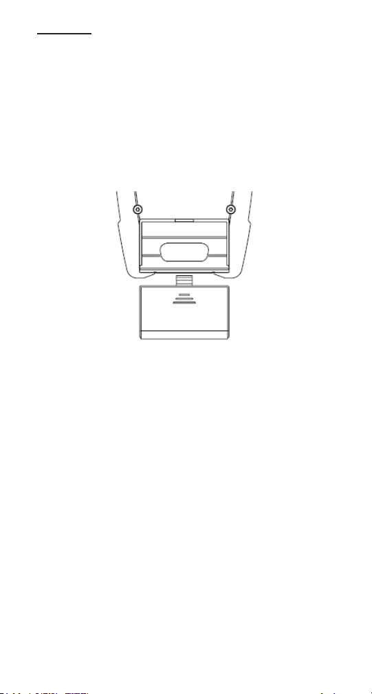
Installation ou remplacement de la batterie
Pour remplacer les batteries, procédez comme suit :
1. Éteignez l’instrument.
2. Retirez le couvercle de la batterie en le faisant glisser vers le bas.
3. Installez une nouvelle batterie sur les ls conducteurs en
respectant la polarité indiquée.
Interface de connexion
Tous les appareils OPM et SLS berTOOLS nécessitent un adaptateur
à visser pour les congurations SC, LC, FC et ST. Les adaptateurs des
instruments OPM et SLS sont uniques car les adaptateurs traversants
prévus pour les OPM sont différents de ceux pour les SLS. N’essayez
pas d’utiliser un adaptateur OPM sur un SLS ou vice versa. Pour les
références des adaptateurs, consultez le chapitre de ce mode d’emploi
consacré aux accessoires.
55
Page 56

Nettoyage des interfaces OPM et SLS
①① Fiber Optic Input
OPM510 & OPM520 is available with SC fiber optic connector
(Interchangeable LC/ST/FC).
②② Ext. AC Power Jack
OPM510 & OPM520 can be operated with an External Power Adapter 9V
DC@250mA.
Assurez-vous que l’instrument est éteint. Ne regardez jamais dans la
sortie d’un port SLS. Dévissez l’adaptateur OPM et utilisez un chiffon
propre non pelucheux pour nettoyer la fenêtre apparente du détecteur
OPM. Utilisez toujours un écouvillon de nettoyage de 2,5 mm neuf pour
nettoyer l’adaptateur traversant SLS.
Fonctionnement de l’OPM
Instructions concernant le connecteur externe
1. Entrée bre optique
2. Prise d’alimentation externe CA
Les OPM510 et OPM520 sont disponibles avec
connecteur de bre optique SC (LC / ST / FC
interchangeables).
Les OPM510 et OPM520 peuvent être utilisés
avec un adaptateur d’alimentation externe 9 V
CC à 250 mA.
Fonctions du clavier
: Appuyez sur le bouton d’alimentation pour allumer ou éteindre
l’OPM. Le paramétrage par défaut éteindra l’OPM après cinq minutes
d’inactivité. Maintenez le bouton d’alimentation enfoncé pendant deux
secondes pour mettre l’OPM en mode constant allumé. Maintenez à
nouveau le bouton d’alimentation enfoncé pendant deux secondes pour
revenir au mode d’arrêt automatique.
dB/dBm: Appuyez sur cette touche pour basculer entre dB et dBm.
Zéro: Appuyez sur la touche Zéro pour mettre à zéro l’OPM avec le
port d’entrée protégé de la lumière ambiante. Le message « SUCC
» s’afchera une fois la remise à zéro réussie. Si le message « ERR
» apparaît, vériez que le port d’entrée était correctement couvert,
et répétez la procédure de remise à zéro. La remise à zéro de l’OPM
supprimera les effets de tout courant d’obscurité inhérent à la diode de
détection.
REF: Appuyez sur la touche REF pour établir une référence de 0 dB
: Appuyez sur cette touche pour sélectionner la longueur d’onde
souhaitée. La longueur d’onde actuelle s’afchera sur l’écran LCD.
56
Page 57
OPM510 • OPM520 • SLS520 • SLS525 • SLS530 • SLS535 • SLS536
①① Fiber Optic Input
OPM510 & OPM520 is available with SC fiber optic connector
(Interchangeable LC/ST/FC).
②② Ext. AC Power Jack
OPM510 & OPM520 can be operated with an External Power Adapter 9V
DC@250mA.
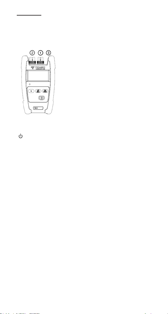
Fonctionnement du SLS
Instructions concernant le connecteur externe
1. Sortie de bre optique
2. Prise d’alimentation externe CA
Le SLS est fourni avec connecteur bre optique SC
/ PC (LC / FC / ST interchangeables). Il s’agit d’un
connecteur poli sans angle. Ne connectez pas de connecteur poli à angle à l’adaptateur traversant.
Le SLS peut être utilisé avec un adaptateur
d’alimentation externe 9 V CC à 250 mA.
Fonctions du clavier
: Allumer ou éteindre l’instrument. Avec le réglage par défaut, le
SLS préservera l’autonomie de la batterie en s’éteignant automatiquement si vous n’appuyez sur aucune touche pendant environ 5 minutes.
μW/Bm: Appuyez sur cette touche pour basculer le mode d’afchage
entre la puissance absolue (dBm) et le microwatt (μW). La puissance
optique actuelle sera afchée sur l’écran LCD.
CW/Mod: Appuyez sur cette touche pour basculer la sortie du SLS entre
CW (onde entretenue) et la fréquence de modulation souhaitée.
: Appuyez sur cette touche pour sélectionner la longueur d’onde
souhaitée. La longueur d’onde actuelle sera afchée sur l’écran LCD.
57
Page 58
Applications
Ce mode d’emploi décrit les applications suivantes des instruments
berTOOLS :
• Mesures de la perte d’insertion du connecteur ou câble
• Mesures de la perte de liaison
Méthode à un cavalier de test : perte de connecteur
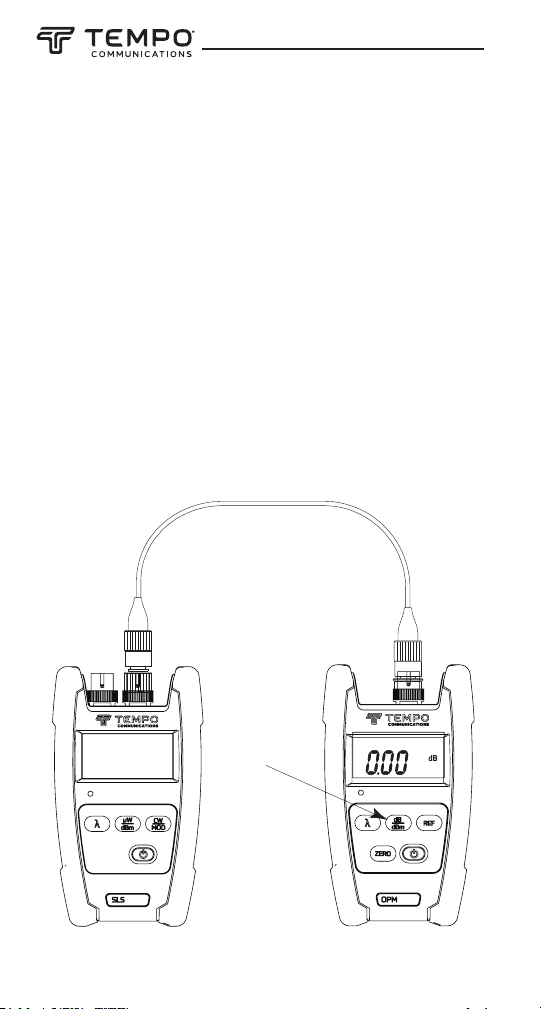
1. Connectez une source lumineuse appropriée au wattmètre optique
à l’aide d’un câble de référence adapté d’une longueur d’environ 2 à
3 mètres (6 à 10 pieds).
2. Assurez-vous que la source lumineuse est en mode de sortie onde
entretenue (CW). Réglez le wattmètre optique sur la longueur d’onde
appropriée (en utilisant la touche [λ]) et sur les unités dBm (en
utilisant la touche [dB/dBm]).
3. Pour conserver le niveau de référence, appuyez sur la touche
[dB/dBm] du wattmètre optique jusqu’à ce que l’écran afche 0,00
dB. Voir ci-dessous.
Appuyez sur la
Press the
touche [dB/dBm]
[dB/dBm]
pour régler la
key to set the
référence de 0 dB
0 dB reference
Wattmètre
Source
Power meter
58
Page 59
OPM510 • OPM520 • SLS520 • SLS525 • SLS530 • SLS535 • SLS536
Méthode à un cavalier de test : perte de connecteur
(suite)
4. Débranchez l’extrémité du câble de référence du wattmètre optique
et insérez le câble à tester à l’aide d’un adaptateur correspondant.
Le wattmètre optique indique la mesure de perte du connecteur ou
du câble en dB.
Câble ou connecteur testé
Cable/connector
under test
Source
Wattmètre
Power meter
59
Page 60
Méthode à deux cavaliers de test : perte de lien
Cavalier de test 1
Test jumper 1
P1
Source Power meter
Cavalier de test 2
Test jumper 2
Wattmètre
Installation
Cable
plant
A
câblée
Source Power meter
60
B
P2
Wattmètre
Page 61
OPM510 • OPM520 • SLS520 • SLS525 • SLS530 • SLS535 • SLS536
Méthode à deux cavaliers de test : perte de liaison
(suite)
1. Si un ensemble de test complet (source lumineuse et wattmètre
optique) est disponible à chaque extrémité, il est conseillé de tester
la puissance de sortie des sources et l’état des cavaliers de test
avant de procéder à la mesure de la liaison.
Connectez chacune des sources et le wattmètre optique avec un
cavalier de test, comme illustré ci-dessus. Les sources doivent être
réglées sur le mode de sortie onde entretenue (CW). Les wattmètres
doivent être réglés sur la bonne longueur d’onde et sur les unités de
mesure dBm. Notez les mesures dBm P1 et P2. Par exemple, avec
une source laser SLS520 de 1310 nm, le wattmètre optique doit
indiquer environ - 1 dBm.
Installation
Cable
câblée
plant
A B
PERTE DIRECTE (dB) = P1 - P3
FORWARD LOSS (dB) = P1 – P3
Cavalier de test 1
Test
jumper 1
Cavalier de test 2
Test
jumper 2
P3
Source Power meter
Wattmètre
61
Page 62
Méthode à deux cavaliers de test : perte de liaison
Source
P4
Power meter
Test
jumper 1
Test
jumper 2
A B
Cable
plant
REVERSE LOSS (dB) = P2 – P4
(suite)
2. Connectez une source lumineuse et un wattmètre optique aux ports
respectifs du tableau de raccordement à l’aide des cavaliers de test,
comme illustré à gauche.
3. À l’aide de la formule ci-dessus, prenez la mesure en dBm sur le
wattmètre optique (P3) et la valeur nominale de sortie de la source,
correspondant à la source lumineuse utilisée.
Remarque : assurez-vous que la longueur d’onde de la source
lumineuse utilisée se situe dans la plage prise en charge par le
wattmètre optique.
Installation
câblée
PERTE INVERSE (dB) = P2 - P4
Cavalier de test 1
Cavalier de test 2
4. Il est conseillé de mesurer la perte dans les deux sens. Inversez
les connexions de la source et du wattmètre optique, comme
illustré ci-dessus. Calculez la perte inverse en utilisant la formule
ci-dessus.
5. Rapportez à la fois les valeurs de perte directe et de perte inverse.
62
Wattmètre
Page 63

OPM510 • OPM520 • SLS520 • SLS525 • SLS530 • SLS535 • SLS536
Garantie limitée
Tempo Communications Inc. garantit à l’acheteur d’origine de ces produits
qu’ils seront exempts de défauts de fabrication et de matériaux pendant
trois ans, sauf usure normale et utilisation abusive.
Pour toutes les réparations d’instruments de test, vous devez d’abord
demander un numéro d’autorisation de retour à notre service client au
numéro :
sans frais aux États-Unis et au Canada 800-642-2155
Téléphone +1 760 510-0558.
Fax +1 760 598-9263.
Le numéro d’autorisation doit être clairement indiqué sur l’étiquette
d’expédition. Expédiez les appareils avec frais de port prépayés à : Tempo
Repair Center, 1390 Aspen Way, Vista, CA 92081 USA.
Indiquez sur chaque colis : Attention: TEST INSTRUMENT REPAIR.
Pour les appareils non couverts par la garantie (en cas de chute,
d’utilisation incorrecte, etc.), vous pouvez demander un devis de réparation.
Remarque : avant de renvoyer un instrument de test, vériez que les batteries sont complètement chargées.
Tempo Communications
1390 Aspen Way • Vista, CA 92081 • USA
800-642-2155
Tempo Europe Ltd. • Brecon House • William Brown Close
Cwmbran • NP44 3AB • UK • Tel: +44 1633 927 050
www.TempoCom.com
63
Page 64
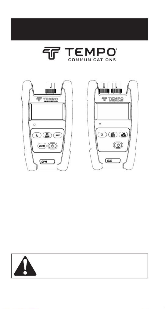
BEDIENUNGSANLEITUNG
OPM510 • OPM520
Glasfaser-Leistungsmesser
SLS520 • SLS530 • SLS535 • SLS536
Laserquelle
SLS525
LED-Quelle
Lesen und verstehen Sie alle Anweisungen und Sicherheitsinformationen in dieser Anleitung, bevor Sie
dieses Gerät in Betrieb nehmen oder warten.
Registrieren Sie dieses Produkt unter www.TempoCom.com
55501380 REV0 © 2022 Tempo Communications Inc. 01/22
Page 65

OPM510 • OPM520 • SLS520 • SLS525 • SLS530 • SLS535 • SLS536
Inhaltsverzeichnis
Beschreibung ........................................................................................66
Sicherheit .............................................................................................67
Zweck dieser Anleitung.........................................................................67
Wichtige Sicherheitshinweise ..........................................................68-70
Einführung ............................................................................................71
Modellbezeichnungen.....................................................................71
Auspacken und Überprüfung ..........................................................72
Technische Daten .................................................................................73
OPM ................................................................................................73
SLS .................................................................................................74
Allgemeine Informationen ....................................................................75
Automatische Abschaltfunktion .....................................................75
Einsetzen oder Austauschen der Batterie .......................................76
Schnappverbindungs-Schnittstelle ................................................76
Betrieb ..................................................................................................77
OPM ................................................................................................77
SLS .................................................................................................78
Anwendungen .......................................................................................79
Anwendungen ............................................................................79-80
Zwei-Test-Jumper-Methode: Verbindungsdämpfung ................81-83
Garantie ................................................................................................84
BEWAHREN SIE DIESE ANLEITUNG AUF
65
Page 66

Beschreibung
Bei den berTOOLS™ -Instrumenten von Tempo Communications
handelt es sich um tragbare Glasfaserwerkzeuge zur Messung der
optischen Leistung und der Verbindungsdämpfung in Multimode- und
Singlemode-Glasfasernetzwerken.
• Der Leistungsmesser OPM510 misst die optische Leistung bei 850
nm, 1300 nm, 1310 nm, 1490 nm, 1550 nm und 1625 nm in einem
Leistungsbereich von +10 bis -65 dBm. Das OPM510 wird standardmäßig mit einem SC-Schottadapter mit optional erhältlichen LC-,
ST- und FC-Adaptern geliefert.
• Der Leistungsmesser OPM520 misst die optische Leistung bei
850 nm, 1300 nm, 1310 nm, 1490 nm, 1550 nm und 1625 nm in
einem Leistungsbereich von +27 bis -50 dBm. Das OPM520 wird
standardmäßig mit einem SC-Schottadapter mit optional erhältlichen
LC-, ST- und FC-Adaptern geliefert.
• Die Laserquelle SLS520 bietet eine Lichtquelle bei 1310 nm
und 1550 nm zur Messung der Einfügedämpfung bei SinglemodeGlasfaserkabeln. Das SLS520 wird standardmäßig mit einem
SC-Schottadapter mit optional erhältlichen LC-, ST- und FC-Adaptern
geliefert.
• Die LED-Quelle SLS525 bietet eine Lichtquelle mit 850 nm und
1300 nm zur Messung der Einfügedämpfung bei MultimodeGlasfaserkabeln. Das SLS525 wird standardmäßig mit einem
SC-Schottadapter mit optional erhältlichen LC-, ST- und FC-Adaptern
geliefert. Die modale Inbetriebnahme wird nicht geregelt.
• Die Laserquelle SLS530 bietet eine Lichtquelle mit 1310 nm,
1490 nm und 1550 nm zur Messung der Einfügedämpfung bei
Singlemode-Glasfaserkabeln. Das SLS530 wird standardmäßig
mit einem SC-Schottadapter mit optional erhältlichen LC-, ST- und
FC-Adaptern geliefert.
• Die Laserquelle SLS535 bietet eine Lichtquelle mit 1310 nm,
1550 nm und 1625 nm zur Messung der Einfügedämpfung bei
Singlemode-Glasfaserkabeln. Das SLS535 wird standardmäßig
mit einem SC-Schottadapter mit optional erhältlichen LC-, ST- und
FC-Adaptern geliefert.
• Die Laserquelle SLS536 bietet eine Lichtquelle mit 1310 nm,
1550 nm und 1650 nm zur Messung der Einfügedämpfung bei
Singlemode-Glasfaserkabeln. Das SLS536 wird standardmäßig
mit einem SC-Schottadapter mit optional erhältlichen LC-, ST- und
FC-Adaptern geliefert.
66
Page 67

OPM510 • OPM520 • SLS520 • SLS525 • SLS530 • SLS535 • SLS536
Sicherheit
Sicherheit ist bei der Verwendung und Wartung von Instrumenten
und Geräten von Tempo Communications von entscheidender
Bedeutung. Diese Bedienungsanleitung und alle Kennzeichnungen
auf dem Werkzeug liefern Informationen zur Vermeidung von
Gefahren und unsicheren Praktiken im Zusammenhang mit der
Verwendung dieses Werkzeugs. Beachten Sie alle bereitgestellten
Sicherheitsinformationen.
Zweck dieser Anleitung
Diese Bedienungsanleitung soll das gesamte Personal mit den sicheren
Betriebs- und Wartungsverfahren für die berTOOLS-Instrumente
OPM510, OPM520, SLS520, SLS525, SLS530, SLS535 und SLS536 von
Tempo Communications vertraut machen.
67
Page 68
Wichtige Sicherheitshinweise
GEFAHRENSYMBOL
Dieses Symbol wird verwendet, um Sie auf Gefahren oder
unsichere Praktiken aufmerksam zu machen, die zu Verletzungen
oder Sachschäden führen können. Das nachstehend denierte
Signalwort gibt die Schwere der Gefahr an. Die Nachricht nach
dem Signalwort enthält Informationen, zur Verhinderung oder
Vermeidung der Gefahr.
Unmittelbare Gefahren, die, wenn sie nicht vermieden werden, zu
schweren Verletzungen oder zum Tod führen WERDEN.
Gefahren, die, wenn sie nicht vermieden werden, zu schweren oder
tödlichen Verletzungen führen KÖNNEN.
Gefahren oder unsichere Praktiken, die, wenn sie nicht vermieden
werden, EVENTUELL zu Verletzungen oder Sachschäden führen.
Lesen und verstehen Sie dieses Material, bevor
Sie dieses Gerät in Betrieb nehmen oder warten.
Wenn Sie nicht verstehen, wie man dieses
Werkzeug sicher bedient, kann dies zu einem
Unfall mit schweren Verletzungen oder Tod
führen.
Gefahr eines Stromschlags:
Der Kontakt mit Stromkreisen kann zu schweren
Verletzungen oder Tod führen.
68
Page 69

OPM510 • OPM520 • SLS520 • SLS525 • SLS530 • SLS535 • SLS536
Wichtige Sicherheitshinweise
Bei den Instrumenten SLS520, SLS530, SLLS535 und SLS5336 handelt
es sich um Lasergeräte, die den Anforderungen CFR 1040 des CDRH
entsprechen. Obwohl durch direkte Exponierung des bloßen Auges
keine Gefahr für Schäden besteht, sollten Benutzer immer vermeiden,
direkt in den Ausgangsanschluss zu blicken. Die Verwendung von
optischen Betrachtungsinstrumenten wie Mikroskopen, Lupen usw.
sollte stets vermieden werden. Die Verwendung solcher Geräte in der
Nähe aktiver Fasern kann einen intensiven Lichtenergiestrahl auf die
Netzhaut des Auges bündeln, was zu dauerhaften Schäden führen
kann.
Gefahr durch Laser:
• Vermeiden Sie bei der Durchführung von Messungen an
Glasfasersystemen, dass die Augen offenen Fasern, optischen
Anschlüssen, optischen Schnittstellen oder anderen Quellen
ausgesetzt werden, da diese mit aktiven Laser-Sendern verbunden
sein können.
• Schauen Sie nicht in den optischen Anschluss, wenn eine Quelle
eingeschaltet ist.
• Vermeiden Sie es, auf das freie Ende einer Testfaser zu schauen,
d. h. auf das Ende, das nicht mit dem Instrument verbunden ist.
Richten Sie das freie Ende wenn möglich auf eine nicht reflektierende Oberfläche.
Die Nichtbeachtung dieser Vorsichtsmaßnahmen kann zu
Verletzungen führen.
69
Page 70

Wichtige Sicherheitshinweise
Gefahr eines Stromschlags:
• Legen Sie Batterien nicht mit umgekehrter Polarität ein.
• Öffnen Sie das Gehäuse des Geräts unter keinen Umständen. Es
enthält keine Teile, die vom Benutzer gewartet werden können.
• Verwenden Sie dieses Gerät nur für den vom Hersteller
vorgesehenen Zweck, wie in dieser Anleitung beschrieben. Jede
andere Verwendung kann den durch das Gerät gebotenen Schutz
beeinträchtigen.
Die Nichtbeachtung dieser Vorsichtsmaßnahmen kann zu
Verletzungen führen und das Gerät beschädigen.
Gefahr der Beschädigung des Instruments:
• Setzen Sie das Gerät nicht direktem Sonnenlicht oder der Nähe
von direkten Wärmequellen aus.
• Schützen Sie das Gerät vor starken Stößen oder Erschütterungen.
• Tauchen Sie das Gerät nicht ins Wasser und lagern Sie es nicht in
Bereichen mit hoher Luftfeuchtigkeit.
• Reinigen Sie bei Bedarf das Gehäuse, die Frontplatte und die
Gummiabdeckung mit einem feuchten Tuch. Verwenden Sie keine
Scheuermittel, aggressiven Chemikalien oder Lösungsmittel.
• Setzen Sie die Staubschutzkappe(n) der Schnittstelle wieder auf,
wenn das Gerät nicht in Gebrauch ist.
• Bewahren Sie das Gerät und die Schnittstellenadapter an einem
kühlen, trockenen und sauberen Ort auf.
Die Nichtbeachtung dieser Vorsichtsmaßnahmen kann zu
Verletzungen führen und das Gerät beschädigen.
70
Page 71

OPM510 • OPM520 • SLS520 • SLS525 • SLS530 • SLS535 • SLS536
Einführung
Modellbezeichnungen
Die berTOOLS-Instrumente verfügen über verschiedene Arten von
Schnittstellen und müssen mit den kompatiblen Adaptern verwendet
werden.
berTOOLS Einzelinstrumente
OPM510 Optischer InGaAs-Leistungsmesser
OPM520 Optischer InGaAs-Leistungsmesser mit hohem
Leistungsmessbereich
SLS520 1310/1550 nm Laserquelle mit SC-Anschluss
SLS525 850/1300 nm LED-Quelle mit SC-Anschluss
SLS530 1310/1490/1550 nm Laserquelle mit SC-Anschluss
SLS535 1310/1550/1625 nm Laserquelle mit SC-Anschluss
SLS536 1310/1550/1650 nm Laserquelle mit SC-Anschluss
berTOOLS Instrumenten-Kits
SM DUAL KIT OPM510 & SLS520
SM DUAL KIT HP OPM520 & SLS520
MM DUAL KIT OPM510 & SLS525
SM T PON KIT OPM510 & SLS530
SM T 1625 KIT OPM510 & SLS535
SM T 1650 KIT OPM510 & SLS536
SM T PON KIT HP OPM520 & SLS530
SM T 1625 KIT HP OPM520 & SLS535
SM T 1650 KIT HP OPM520 & SLS536
SMMMKIT-T OPM510, SLS520 & SLS525
SMMMKIT-M OPM520, SLS520 & SLS525
Tempo Communications OPM-Adapter
SC-OPM SC-Adapter
LC-OPM LC-Adapter
FC-OPM FC-Adapter
ST-OPM ST-Adapter
SCAPC-OPM SC/APC-Adapter
71
Page 72

Tempo Communications SLS-Adapter
Do not discard this product or throw away!
For recycling information, go to www.TempoCom.com.
SC-Source SC-/UPC-Adapter
LC-Source LC-/UPC-Adapter
FC-Source FC-/UPC-Adapter
ST-Source ST-/UPC-Adapter
Tempo Communications Zubehör
CC-1 Tragetasche, Einzelinstrument
PS-100 Externes Netzteil
CC-2-3 Tragetasche, Doppel- und Dreifachinstrument
Auspacken und Überprüfung
Alle berTOOLS-Instrumente wurden vor dem Versand sorgfältig
geprüft. Bei Erhalt sollte der Versandkarton die nachfolgend aufgeführten Artikel enthalten:
• 1 berTOOLS-Instrument
• 1 weiche Tragetasche
• 1 Kurzleitfaden
Bitte erfassen und überprüfen Sie jeden Artikel, während Sie das
Instrument auspacken und für den Gebrauch vorbereiten.
Wenn das erhaltene Instrument beschädigt ist, wenden Sie sich bitte an
Tempo Communications.
Bewahren Sie den Versandkarton für den Fall auf, dass aus irgendeinem Grund ein erneuter Versand erforderlich ist.
Bitte entsorgen Sie dieses Produkt nicht und werfen Sie es nicht
weg!
Informationen zum Recycling nden Sie unter
www.TempoCom.com.
Alle technischen Merkmale können sich im Zuge von
Entwicklungsverbesserungen ändern. Tempo Communications Inc. haftet nicht
für Schäden, die durch fehlerhafte Anwendung oder Missbrauch seiner Produkte
entstehen.
berTOOLS ist ein Warenzeichen von Tempo Communications Inc.
72
Page 73

OPM510 • OPM520 • SLS520 • SLS525 • SLS530 • SLS535 • SLS536
Technische Merkmale
OPM
MODELL OPM510 OPM520
Kal. Wellenlänge 850, 1300, 1310, 1490, 1550,1625nm
Messbereich -65 to +10dBm -50 to +27dBm
Detektortyp InGaAs
Genauigkeit
Linearität
Auösung 0.01dB
Funktionen
Anschlusstyp SC (austauschbar durch LC, FC und ST)
Fasertyp Singlemode & Multimode
Batterielebensdauer > 100 Stunden
Stromversorgung
Betriebstemperatur -10°C ~ 50°C
Lagertemperatur -20°C ~ 70°C
Relative Luftfeuchtigkeit 0 bis 95 % (nicht kondensierend)
Gewicht 300 g (0,68 lbs)
Abmessungen (H × B × T) 155 × 88 × 33 mm (6,1 × 3,5 × 1,3 Zoll)
IP-Schutzart IP54
Schwingung 5Hz to 150Hz, Amplitude = 0.15mm
Dämpfung
Einhaltung von Richtlinien CE, FCC
+/-0.5dB (+10 to -3dBm)
+/-0.1dB (-3 to -50dBm)
+/-0.5dB (-50 to -65dBm)
MOD-TON-ERKENNUNG 270 Hz, 1 kHz, 2 kHz
9 V Alkaline oder 1000 mAh Lithiumbatterie/9 V AC-
Spitzenbeschleunigung 25 g bei einer Pulsdauer von
±0.25 dB
(±0.5dB@850nm)
+/-0.5dB +27 to -3dBm
+/-0.1dB -3 to -50dBm
µW/dBm/dB(REF)/
adapter
6 ms
(1) Die Untergrenze der 850-nm-Messung liegt für OPM510 bei -60 dBm.
Technische Merkmale können ohne Vorankündigung geändert werden.
73
Page 74
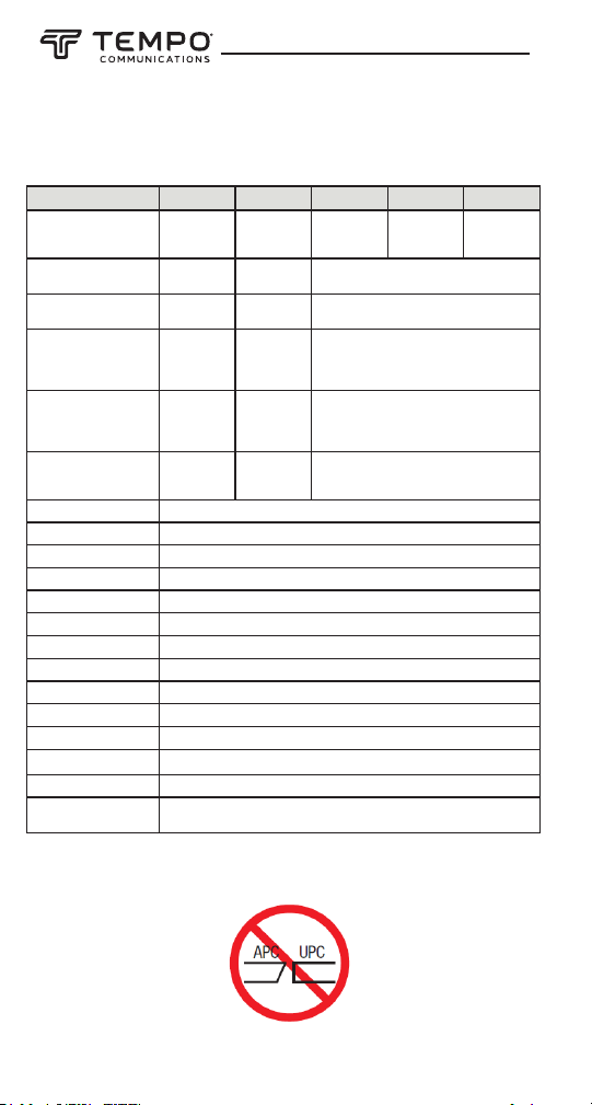
Model
SLS520
SLS525
SLS530
Wavelength (±20nm)
1310/1550
850/1300 1310/1550/1625
1310/1550/1650
1310/1490/1550
Range of Use
Singlemode
Multimode
Singlemode
Emitter Type FP LED
FP
Spectral Width
≤ 5 nm
+/-40 nm
≤ 5 nm
SLS535
SLS536
Technische Merkmale
SLS
MODELL SLS520 SLS525 SLS530 SLS535 SLS536
Wellenlänge 1310/1550nm 850/1300nm
0dBm/
-1dBm
±0.05
Multimode
(62.5/125)
≤ 71nm
(850nm),
≤ 160nm
(1300nm)
-20dBm/
-21dBm
±0.05
dB/15min;
±0.15dB/8hr
Einsatzbereich Singlemode
Emittertyp FP LED FP
Spektrale Breite ≤ 5 nm
Ausgangsleistung
Typisch/
Minimal
Stabilität der Ausgang-
sleistung
Modulationsfrequenz 270Hz, 1kHz, 2kHz
Anzeige LCD
Batterielebensdauer 60 Stunden
Anschlusstyp SC/PC (austauschbar durch LC, ST, SC)
Stromversorgung 9 V Alkaline oder 1000 mAh Lithiumbatterie/9 V AC-Adapter
Betriebstemperatur -10 to +50°C
Lagertemperatur -20 to +70°C
Relative Luftfeuchtigkeit 0 bis 95 % (nicht kondensierend)
Gewicht 300 g (0,71 lbs)
Abmessungen (H × B × T) 155 × 88 × 33 mm (6,1 × 3,5 × 1,3 Zoll)
IP-Schutzart IP54
Schwingung 5Hz to 150Hz, Amplitude = 0.15mm
Dämpfung Spitzenbeschleunigung 25 g bei einer Pulsdauer von 6 ms
Einhaltung von
Richtlinien
dB/15min;
±0.10dB/8hr
1310/
1490/
1550nm
CE, FCC, 21 CFR 1040.10 (laser)
1310/
1550/
1625nm
Singlemode
≤ 5 nm
0dBm/-1dBm
±0.05 dB/15min;
±0.10dB/8hr
1310/
1550/
1650nm
Technische Merkmale können ohne Vorankündigung geändert werden.
74
Page 75

OPM510 • OPM520 • SLS520 • SLS525 • SLS530 • SLS535 • SLS536
Allgemeine Informationen
Dieser Abschnitt enthält allgemeine Anweisungen zur Verwendung der
berTOOLS-Instrumente.
Wenn es die Umstände erfordern, dass die Instrumente hausintern
gewartet und instand gehalten werden müssen, wenden Sie sich bitte
an Tempo Communications, um technische Unterstützung zu erhalten.
Batterie
Die Instrumente OPM510, OPM520, SLS520, SLS525, SLS530,
SLS535 und SLS536 werden von einer 9V-Alkalibatterie oder einer
9V-Lithiumbatterie gespeist.
Das optionale externe Netzteil kann zur Stromversorgung des OPM
und SLS anstelle einer Alkalibatterie verwendet werden. Das externe
Netzteil wird nicht zum Aufladen eines wiederaufladbaren Akkus
verwendet, der im OPM oder SLS installiert werden kann.
Versuchen Sie nicht, Alkalibatterien mit dem externen Netzteil
aufzuladen.
Wenn die Batterieleistung schwach ist, wird die Anzeige für niedrige
Batterieleistung auf dem LCD angezeigt.
Automatische Abschaltung
Das Instrument schaltet sich automatisch ab, wenn etwa fünf Minuten
lang keine Taste betätigt wird.
Um die automatische Abschaltung zu deaktivieren, halten Sie beim
Einschalten die Taste [Ein/Aus] gedrückt, bis „AUTO OFF“ auf der
LCD-Anzeige erscheint. Um die automatische Abschaltung wieder zu
aktivieren, halten Sie die Taste [Ein/Aus] gedrückt, bis „AUTO OFF“ nicht
mehr angezeigt wird.
75
Page 76

Einsetzen oder Austauschen der Batterie
Gehen Sie folgendermaßen vor, um die Batterien auszutauschen:
1. Schalten Sie das Instrument aus.
2. Entfernen Sie die Batterieabdeckung, indem Sie sie nach unten
schieben.
3. Schließe Sie eine neue Batterie an die Kabel an und achten Sie
dabei auf die richtige Polarität.
Verbindungsschnittstelle
Alle berTOOLS OPM- und SLS-Einheiten nutzen einen aufschraubbaren
Adapter für die SC-, LC-, FC- und ST-Kongurationen. Die OPM- und
SLS-Instrumentenschotten sind insofern einzigartig, als sich die OPMAdapter von den SLS-Adaptern unterscheiden. Versuchen Sie nicht,
einen OPM-Adapter auf einem SLS zu verwenden oder umgekehrt.
Informationen zu den Teilenummern der Adapter nden Sie im
Abschnitt Zubehör dieser Bedienungsanleitung.
76
Page 77

OPM510 • OPM520 • SLS520 • SLS525 • SLS530 • SLS535 • SLS536
①① Fiber Optic Input
OPM510 & OPM520 is available with SC fiber optic connector
(Interchangeable LC/ST/FC).
②② Ext. AC Power Jack
OPM510 & OPM520 can be operated with an External Power Adapter 9V
DC@250mA.
Reinigen der OPM- und SLS-Schnittstellen
Stellen Sie sicher, dass das Instrument ausgeschaltet ist. Blicken Sie
nicht in den Ausgang eines SLS-Anschlusses. Schrauben Sie den OPMAdapter ab und reinigen Sie das freigelegte OPM-Detektorfenster mit
einem sauberen fusselfreien Tuch. Verwenden Sie zum Reinigen des
SLS-Schotts immer einen neuen 2,5-mm-Reinigungstupfer.
OPM-Operationen
Anleitung für externen Anschluss
1. Glasfasereingang
OPM510 und OPM520 sind mit
2. Ext. AC-Stromversorgungsanschluss
SC-Glasfaseranschluss erhältlich (austauschbar
durch LC-/ST-/FC-Anschluss).
OPM510 und OPM520 können mit einem
externen 9V-DC-Netzteil mit 250 mA betrieben
werden.
Funktionen der Tastatur
: Drücken Sie die Einschalttaste, um das OPM ein- oder auszuschalten. Die Standardeinstellung schaltet das OPM nach fünf Minuten
Inaktivität aus. Halten Sie die Einschalttaste zwei Sekunden lang
gedrückt, um das OPM in einen dauerhaften Ein-Modus zu versetzen.
Wenn Sie die Einschalttaste erneut zwei Sekunden lang gedrückt
halten, kehrt das Instrument in den automatischen Ausschaltmodus
zurück.
dB/dBm: Drücken Sie diese Taste, um zwischen dB und dBm
umzuschalten.
Zero: Drücken Sie die Zero-Taste, um das OPM auf Null zu stellen,
wobei der Eingangsanschluss vor Umgebungslicht geschützt ist.
Nach erfolgreicher Nullstellung wird die Meldung „SUCC“ angezeigt.
Wenn die Meldung „ERR“ angezeigt wird, überprüfen Sie, ob der
Eingangsanschluss tatsächlich richtig abgedeckt war, und wiederholen Sie die Nullstellung. Durch die Nullstellung des OPM werden die
Auswirkungen des Dunkelstroms der Detektordiode beseitigt.
REF: Drücken Sie die REF-Taste, um eine 0dB-Referenz einzustellen.
: Drücken Sie diese Taste, um die gewünschte Wellenlänge auszu-
wählen. Die aktuelle Wellenlänge wird auf der LCD-Anzeige angezeigt.
77
Page 78

SLS-Operationen
①① Fiber Optic Input
OPM510 & OPM520 is available with SC fiber optic connector
(Interchangeable LC/ST/FC).
②② Ext. AC Power Jack
OPM510 & OPM520 can be operated with an External Power Adapter 9V
DC@250mA.
Anleitung für externen Anschluss
1. Glasfaserausgang
2. Ext. AC-Stromversorgungsanschluss
SLS wird mit SC/PC-Glasfaseranschluss (mit austauschbarem LC-/FC-/ST-Anschluss) geliefert. Es handelt
sich um einen flachen polierten Stecker. Schließen Sie
keine winkelpolierten Steckverbinder an das Schott an.
SLS kann mit einem externen 9V-DC-Netzteil mit 250
mA betrieben werden.
Funktionen der Tastatur
: Schalten Sie das Instrument damit ein oder aus. In der Standardeinstellung
schont das SLS die Batterie, indem es sich automatisch ausschaltet, wenn etwa
fünf Minuten lang keine Taste gedrückt wurde.
μW/Bm: Drücken Sie diese Taste, um den Anzeigemodus von absoluter Leistung
(dBm) auf Mikrowatt (μW) umzuschalten. Die aktuelle optische Leistung wird auf
der LCD-Anzeige angezeigt.
CW/Mod: Drücken Sie diese Taste, um den Ausgang des SLS von CW auf die
gewünschte Modulationsfrequenz umzuschalten .
: Drücken Sie diese Taste, um die gewünschte Wellenlänge auszuwählen. Die
aktuelle Wellenlänge wird auf der LCD-Anzeige angezeigt.
78
Page 79
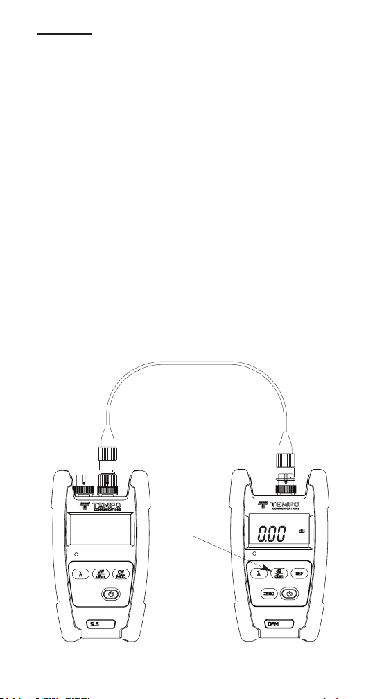
OPM510 • OPM520 • SLS520 • SLS525 • SLS530 • SLS535 • SLS536
Anwendungen
Die folgenden Anwendungen für die berTOOLS-Instrumente werden in
dieser Anleitung beschrieben:
• Messungen der Einfügedämpfung durch Stecker-/Kabel
• Messungen von Verbindungsdämpfungen
Ein-Test-Jumper-Methode: Steckerdämpfung
1. Schließen Sie eine geeignete Lichtquelle mit einem entsprechenden
Referenzkabel mit einer Länge von etwa zwei bis drei Metern (sechs
bis zehn Fuß) an den optischen Leistungsmesser an.
2. Stellen Sie sicher, dass sich die Lichtquelle im Dauerstrich-
Ausgabemodus (Continuous Wave; CW) bendet. Stellen Sie den
optischen Leistungsmesser auf die entsprechende Wellenlänge (mit
der Taste [λ]) und auf dBm-Einheiten (mit der Taste [dB/dBm]) ein.
3. Um den Referenzpegel zu speichern, drücken Sie die Taste [dB/dBm]
am optischen Leistungsmesser, bis auf der Anzeige 0.00 dB
erscheint. Siehe unten.
Source
Drücken Sie
die Taste [dB/
dBm] um die
0-db-Referenz
einzustellen Taste
Press the
[dB/dBm] um die
[dB/dBm]
0-db-Referenz
key to set the
einzustellen
0 dB reference
Leistungsmesser Quelle
Power meter
79
Page 80
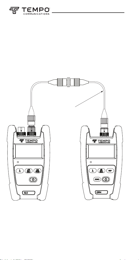
Ein-Test-Jumper-Methode: Steckerdämpfung
(Fortsetzung)
4. Trennen Sie das Referenzkabel vom optischen Leistungsmesser
und stecken Sie das zu prüfende Kabel unter Verwendung eines
geeigneten Verbindungsadapters ein. Der optische Leistungsmesser
zeigt die Stecker /Kabeldämpfung in dB an.
Kabel/Stecker, das/der
Cable/connector
geprüft wird
under test
Leistungsmesser Quelle
Source
80
Power meter
Page 81
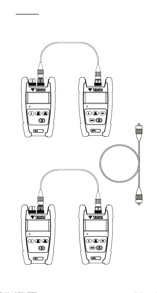
OPM510 • OPM520 • SLS520 • SLS525 • SLS530 • SLS535 • SLS536
Zwei-Test-Jumper-Methode: Verbindungsdämpfung
Test jumper 1
P1
A
Quelle
Source Power meter
Test jumper 2
Leistungsmesser
Kabelleitung
Cable
plant
P2
Source Power meter
Leistungsmesser Quelle
B
81
Page 82
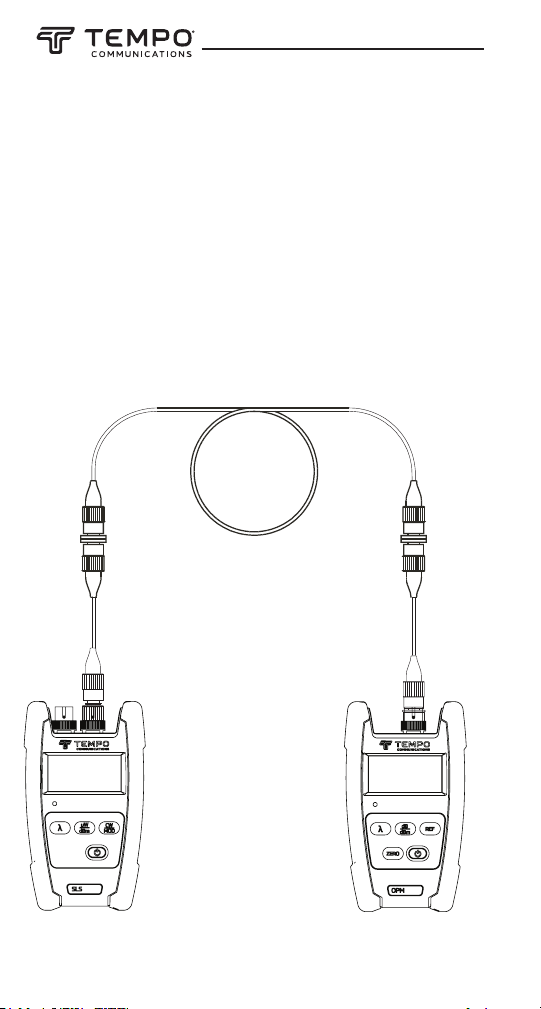
Zwei-Test-Jumper-Methode: Verbindungsdämpfung
(Fortsetzung)
1. Wenn an jedem Ende ein vollständiger Testsatz (Lichtquelle
und optischer Leistungsmesser) verfügbar ist, ist es ratsam, die
Ausgangsleistung der Quellen und den Zustand der Test-Jumper zu
prüfen, bevor Sie mit der Messung der Verbindung beginnen.
Verbinden Sie jede Quelle und jeden optischen Leistungsmesser
mit einem Test-Jumper, wie oben gezeigt. Die Quellen sollten
auf den Dauerstrich-Ausgabemodus (CW) eingestellt sein. Die
Leistungsmesser sollten auf die richtige Wellenlänge und auf dBmMesseinheiten eingestellt sein. Achten Sie auf die P1- und P2-dBmMesswerte. Zum Beispiel sollte eine SLS520-1310-NM-Laserquelle
ungefähr -1 dBm auf dem optischen Leistungsmesser anzeigen.
Kabelleitung
Cable
plant
A B
DÄMPFUNG IN VORWÄRTS-RICHTUNG (dB) = P1 - P3
FORWARD LOSS (dB) = P1 – P3
Test
jumper 1
Source Power meter
82
Test
jumper 2
Leistungsmesser Quelle
P3
Page 83
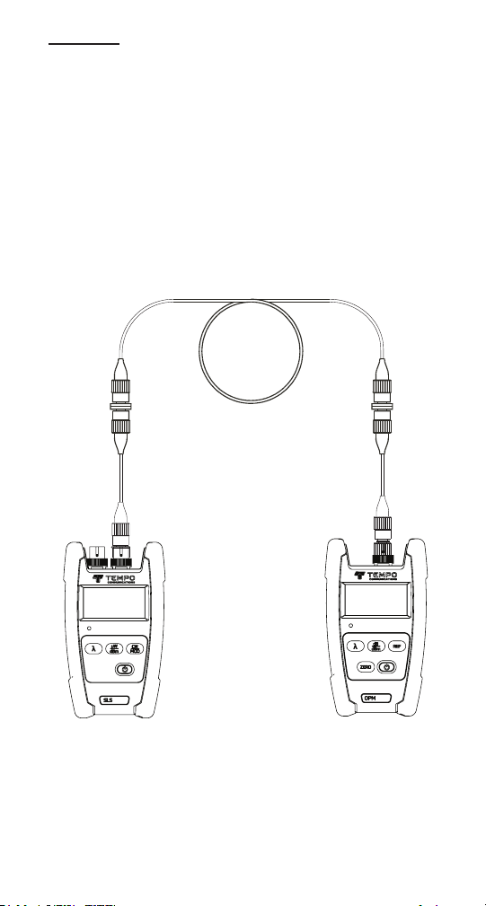
OPM510 • OPM520 • SLS520 • SLS525 • SLS530 • SLS535 • SLS536
Source
P4
Power meter
Test
jumper 1
Test
jumper 2
A B
Cable
plant
REVERSE LOSS (dB) = P2 – P4
Zwei-Test-Jumper-Methode: Verbindungsdämpfung
(Fortsetzung)
2. Schließen Sie eine Lichtquelle und einen optischen Leistungsmesser
mit den Test-Jumpern an die entsprechenden Patch-PanelAnschlüsse, wie links zu sehen, an.
3. Verwenden Sie die oben gezeigte Formel, um den dBm-Messwert
auf dem optischen Leistungsmesser (P3) und den nominalen
Ausgangswert der Quelle zu ermitteln, der der verwendeten
Lichtquelle entspricht.
Hinweis: Stellen Sie sicher, dass der optische Leistungsmesser die
Wellenlänge der verwendeten Lichtquelle unterstützt.
Kabelleitung
DÄMPFUNG IN RÜCKWÄRTS-
RICHTUNG (dB) = P2 - P4
4. Es ist ratsam, die Dämpfung in beiden Richtungen zu messen.
Tauschen Sie die Anschlüsse von Quelle und optischem
Leistungsmesser wie oben gezeigt aus. Berechnen Sie die
Dämpfung in Rückwärtsrichtung mit der oben gezeigten Formel.
5. MeldenSie sowohl die Werte für die Dämpfung in Vorwärts- als
auch in Rückwärtsrichtung.
Leistungsmesser Quelle
83
Page 84

Beschränkte Garantie
Tempo Communications Inc. garantiert dem ursprünglichen Käufer dieser
Waren drei Jahre lang, dass diese Produkte frei von Verarbeitungs- und
Materialfehlern sind, mit Ausnahme von normalem Verschleiß und
Missbrauch.
Für alle Reparaturen an Prünstrumenten müssen Sie zunächst eine
Rückgabeberechtigungsnummer anfordern, indem Sie sich an unseren
Kundendienst wenden:
gebührenfrei in den USA und Kanada 800-642-2155
Telefon +1 760 510-0558.
Fax +1 760 598-9263.
Diese Nummer muss deutlich auf dem Versandetikett angegeben sein.
Schiffseinheiten-Fracht im Voraus bezahlt an: Tempo Repair Center, 1390
Aspen Way, Vista, CA 92081 USA.
Markieren Sie alle Pakete: Achtung: TEST INSTRUMENT REPAIR.
Für Artikel, die nicht unter die Garantie fallen (wie solche, die fallengelas-
sen, unsachgemäß verwendet usw. wurden), ist ein Kostenvoranschlag für
die Reparatur auf Anfrage erhältlich.
Hinweis: Bitte überprüfen Sie vor der Rücksendung eines Prünstruments,
dass die Batterien vollständig aufgeladen sind.
Tempo Communications
1390 Aspen Way • Vista, CA 92081 • USA
800-642-2155
Tempo Europe Ltd. • Brecon House • William Brown Close
Cwmbran • NP44 3AB • UK • Tel: +44 1633 927 050
www.TempoCom.com
 Loading...