

tempmate IR20 Instruction manual
Infrared thermometer
Instruction manual
I
N
F
RAR
E
D T
-5
0 C ~ 70
0 C (
Version:IR20-EN-00
38mm@
75mm@
900mm
3.0" @
36"
132mm@
1500mm
5.3" @
60"
MODEL:IR20
A. Introduction
This infrared thermometer is used for measuring the temperature of the object's surface, which is applicable for various hot, hazardous or hard-toreach objects without contact
safe and quickly.
This unit consist of Optics, Temperature Sensor Signal
amplifier, Processing circuit and LCD Display. The Optics
collected the infrared energy emitted by object and focus onto
the Sensor. Then the sensor translates the energy into an
electricity signal. This signal will be turned out to be digital
shown on the LCD after the signal amplifier and processing
circuit.
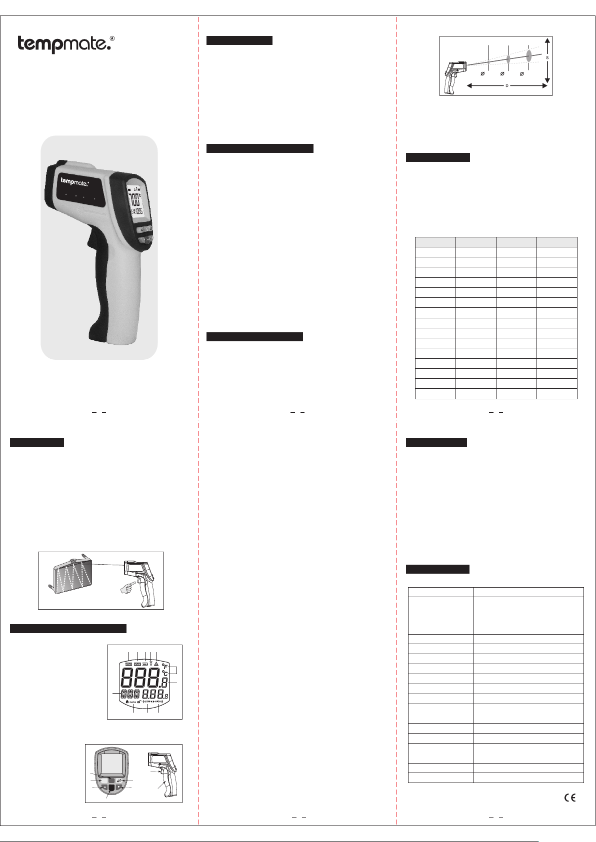
D:S=12:1
2. Field of view:
Make sure the target is larger than the unit's spot size.
The smaller the target the closer measure distance.
When accuracy is critical, make sure the target is at least
twice as large as the spot size.
300mm
1.5" @
12"
B. WARNING & CAUTIONS
1. Warning:
To avoid the potential situation may cause harm or dam-
-
I
R20
H
ERM
OM
ET
ER
-
5
8 F ~ 1
29
2 F)
age to people, please pay attention to the following items:
1) . Do not point laser directly at eye or indirectly off reflec tive surfaces.
2) . The unit cannot measure through transparent surfaces
such as glass or plastic. It will measure the surface tem perature of these materials instead.
3) . Steam, dust, smoke, or other particles can prevent acc urate measurement by obstructing by the units optics.
2. Caut io ns:
Infra re d therm om eter sh ou ld b e pro te ct ed for th e
follo wi ng:
1). EMF ( el ectro -m agnet ic f ie lds ) fr om a rc weld er s,
induc ti on heat er s.
2). The rmal sh oc k (caus e by l ar ge or a br up t ambie nt
tempe ra ture ch an ges all ow 3 0 mi nut es f or u nit to
stabi li ze befo re u se).
3). Do no t le ave the u ni t on or nea r ob je cts o f hi gh
tempe ra ture.
C. Distance to spot size
1. When take measurement, pay attention to the Distance
to Spot Size. As the Distance (D) from the target surface
increases, the spot size (S) of the area measured by the
unit becomes larger.
The Distance to Spot size of the unit is 12:1.
This unit is equipped with a laser, which is used for aiming.
D. EMISSIVITY
Emiss iv ity: Mo st o rgani c ma te ria ls a nd p ainte d or
oxidi ze d surfa ce s have an e mi ss ivi ty o f 0. 95(pr es et in
the uni t) . Inacc ur ate rea di ng s wil l re su lt from m ea surin g
shiny o r po lishe d me tal sur fa ce s. To com pe nsate f or t his,
adjus t th e units e mi ssivi ty r ea din g or c ov er the su rf ace to
be meas ur ed with m as king ta pe o r fl at bl ac k pa int.
Measu re t he tape o r pa inted s ur fa ce wh en t he t ape or
paint ed r each th e sa me temp er at ure a s th e ma teria l
under ne ath.
Marte ri al
Alumi nu m
Asbes to s
Aspha lt
Basal t
Brass
Brick
Carbo n
Ceram ic
Concr et e
Coppe r
Dirt
Froze n fo od
Hot foo d
Glass (p la te)
Ice
Emiss iv it y
0.30
0.95
0.95
Limes to ne
0.70
0.50
0.90
0.85
0.95
0.95
0.95
0.94
0.90
0.93
0.85
0.98
Marte ri al
Lead
Paint
Paper
Plast ic
Rubbe r
Sand
Snow
Steel
Textile s
Wat er
Woo d
Iron
Oil
Skin
Emiss iv it y
0.70
0.50
0.98
0.94
0.93
0.95
0.95
0.95
0.90
0.98
0.90
0.80
0.94
0.93
0.94
E. Operation
1. Operating the unit:
1). Open the battery door and insert a 9V battery properly.;
2). Pull the trigger to turn on the unit;
3). Aim at the target surface and pull the trigger, then temp erature will be shown on the LCD.
This unit is equipped with a laser, which is only used for
aiming.
2. Locating a Hot Spot:
To find a hot spot, aim the thermometer outside of interest,
then scan across with an up and down motion until you
locate the hot spot. (Figure 1)
Figure 1
F. LCD display & buttons
1.LCD d is play:
A: Meas ur ing rea di ng
B: Meas ur ing uni t
C: Lase r on i con
D: Back li ght on ic on
E: Batt er y power i co n
F: Scan ni ng icon
G: Data h ol d icon
H: Mode /e missi vi ty indi ca to r
I: Data s to rge / rea d ic on
J: Low te mp eratu re a larm ic on
K: High t em perat ur e alarm i co n
Diagram description
2. :
(figure 2)
6
4
5
H
STO
SET
CAL
MODE
3
I J K
2
5
Figure 2
CDEFG
B
A
1
7
21 3
(1) Trig ge r: When t ur n on LCD di sp la y VER XX s of tware
versi on f or 1 sec. An d tu rn to dis pl ay r ead in g wi th
SCAN ic on . Relea se t he trig ge r, di spl ay r ea ding wi th
HOLD ic on . Built i n au to powe r of f in 7s ec .
(2) Las er / b ack lig ht b utton : wh en b ack l ig ht t urn on ,
any ope ra tions w il l remai n ba ck l igh t fo r 10 s ec. LCD
indic at e on/of f statu s.
(3)—(6) k ey f uncti on s: pres s 3 ke y, LCD s ub di spl ay
blink s MA X-MIN -D IF-AVG -HAL- LA L- STO -E MS se g ment( on ly main d is play me an s no rma l me as uring
mode) p re ss 4 key to e nt er.
a. MAX: m ea surin g ma ximum t em pe rat ur e
b. MIN: m ea surin g mi nimum t em pe rat ur e
c. DIF: B as ic on the r ea ding be fo re p res s 4 ke y,
compu te t he diff erenc e of c ur ren t re ad ing .
d. AVG: m ea surin g av erage t em pe rat ur e
e. HAL: h ig h tempe ra ture al ar m- -wh en s el ected H AL ,
press 5 k ey s to set hi gh t emper at ur e ala rm t ri gger
and con fi rmed by p re ssing 4 k ey. When r ea di ng over
trigg er, L CD disp la y HI icon w it h Bi Bi au di o so unds.
f. LAL: l ow t emper at ure ala rm -- whe n se le cted LA L,
press 5 k ey s to set lo w te mpera tu re a lar m tr ig ger and
confi rm ed by pre ss ing 4 key.
When re ad ing ove r tr igger, L CD d is pla y LO W ic on
with Bi Bi a udio so un ds
g. STO: d ata sto ra ge--w he n se lec te d STO , lo ck & D ATA
& 1---i nd icato r wi ll show n wh en p res s 4 ke y. Afte r
tempe ra ture re ad o ut pres s 6 ke y to s tor e, t he n 2-- memor y un it will b e sh own. Th er e 30 gr ou ps m emory
unit av ai lable . To recall t he s to red d at a in n ormal
measu ri ng mode b y pr essin g 6 ke y, rem ov e al l data
by pres si ng 6 keys f or 3 s econd s.
H. EMS: E mi ssivi ty s etup- - pr es s 5 key f or e mi ssi vi ty
setti ng s, pres s 4 ke y to save s et up and ba ck t o
norma l st atus.
(7) Cle si us / Fahr en heit sw it ch : Ple as e op en batt er y
and pus h th e slide s wi tch for c on ve rts io n.
G. Maintenence
1. Lens Cleaning:
Blow off loose particles using clean compressed
air. Gently brush remaining debris away with a
moist cotton swab. The swab may be moistened
with water.
2. Case cleaning: Clean the case with a damp spo nge/cloth and mild soap.
Note:
1) Do not use solvent to clean plastic lens.
2) Do not submerge the unit in water.
H. Specification
Temperature range
Accuracy
Resolution
Repeatability
Response time
Spectral response
Emissivity
Distance to Spot size
Operating Temperature
Operating Humidity
Storage Temperature
Power
Typical battery life
(Alkaline)
Weight
Dimension
-50 ~7 00℃ (- 58 ~12 92℉)
0~700℃(32~1292℉) :±1.5℃(±2.7℉)
or±1.5%
-50~0℃(-58~32℉):±3℃ (±5℉)
Whichever is greater
0.1℃ or 0. 1℉
1% of rea din g or 1℃
500 mSe c, 95 % re spo ns e
8-14 um
0.1 0~ 1.0 0 Adj us tab le ( 0.9 5 Pr ese t)
12:1
0 ~40℃ (32 ~ 1 04℉)
10~95 %RH n on -co nd ens in g,
up to 3 0℃(8 6℉)
-20 ~ 60℃ (- 4~1 40℉)
9V Al kal in e or Ni Cd b att er y
Non-l ase r mo de: 2 2 hr s;
Laser M ode ls :12 h rs
222g
111*50*172mm
MADE IN C HIN A
5 64
 Loading...