

Page 1
Tornado G4 User Manual 1
User Manual
Tornado G4
Tornado Marine G4
Revision 01.4
August 2017
© Tempest Lighting, Inc.
Page 2

Tornado G4 User Manual 2
Table of Contents
Table of Contents ........................................................................................................................................................................................ 2
Approvals – North America .................................................................................................................................................................... 4
Approvals – Europe ................................................................................................................................................................................ 5
Approvals – China ................................................................................................................................................................................... 6
Introduction ................................................................................................................................................................................................ 7
IMPORTANT: Safety Advisories .............................................................................................................................................................. 7
Installation ................................................................................................................................................................................................... 8
Dimensions, Rigging Points, and Maximum Luminaire Dimensions/Power ........................................................................................ 8
Airflow Clearance ............................................................................................................................................................................. 10
Snow Clearance ................................................................................................................................................................................ 10
Mounting Hardware Options ............................................................................................................................................................... 11
Mounting Bolts ................................................................................................................................................................................. 11
Globe Down Tornado Enclosures .................................................................................................................................................... 11
Horizontal Tornado Enclosures ........................................................................................................................................................ 11
Drainage ................................................................................................................................................................................................ 12
Wiring the Enclosure ................................................................................................................................................................................ 13
Power Wiring ........................................................................................................................................................................................ 13
SAFETY NOTICE ................................................................................................................................................................................. 13
Electrical Standards .......................................................................................................................................................................... 13
Wiring Access – Globe-up Models ................................................................................................................................................... 13
Wiring Access – Globe-down and Horizontal Models .................................................................................................................... 14
One or Two Power Circuits? ............................................................................................................................................................ 15
Single Feed Power Termination ....................................................................................................................................................... 16
Split Feed Power Termination ......................................................................................................................................................... 16
AC Supply Voltage............................................................................................................................................................................. 16
Wiring – North America/Japan 200-208VAC .................................................................................................................................. 17
Wiring – International 220-250VAC ................................................................................................................................................ 18
Remote Monitoring Connections ........................................................................................................................................................ 19
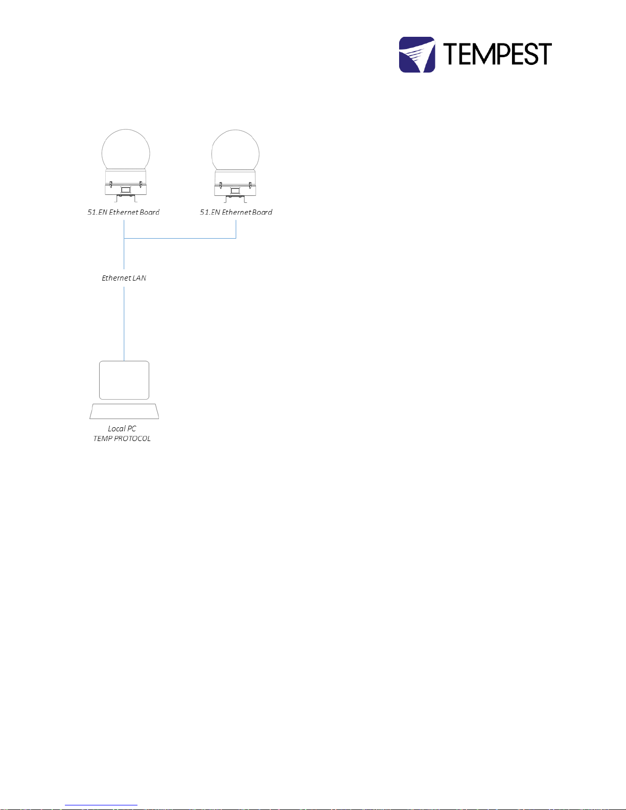
Direct Ethernet Monitoring Network .............................................................................................................................................. 20
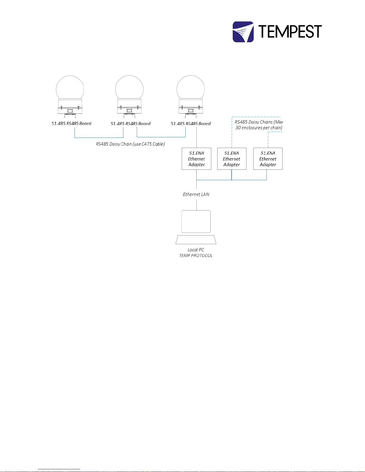
RS485 to Ethernet TEMP Monitoring Network ............................................................................................................................... 21
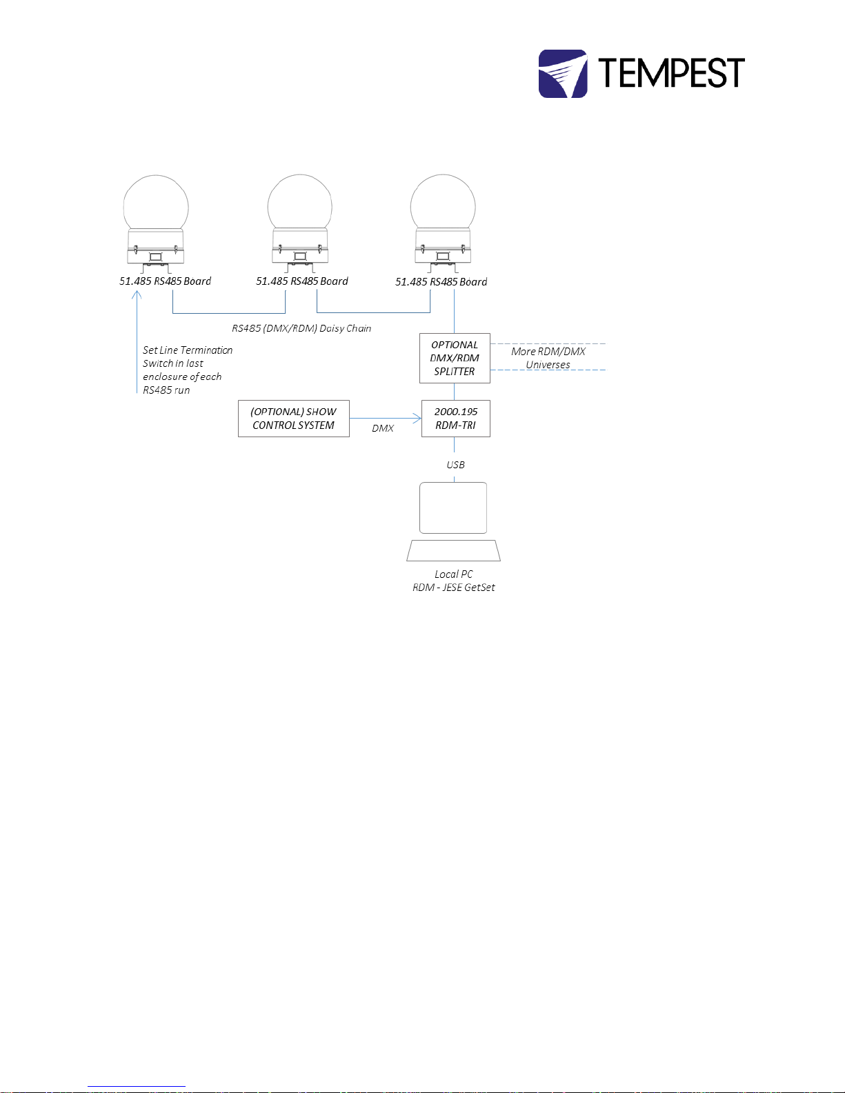
DMX/RDM Monitoring Network ...................................................................................................................................................... 22
RS485 (DMX/RDM) Cable Terminations .......................................................................................................................................... 23
Luminaire Power Control using DMX512 ........................................................................................................................................ 23
Digital Enclosure Control .......................................................................................................................................................................... 24
Schematic .............................................................................................................................................................................................. 24
DEC4 Main Functions ........................................................................................................................................................................... 25
Page 3

Tornado G4 User Manual 3
Factory Settings – Basic Mode ............................................................................................................................................................. 25
Other Operating Modes ....................................................................................................................................................................... 26
Monitor Mode .................................................................................................................................................................................. 26
Control Mode.................................................................................................................................................................................... 26
Service Mode .................................................................................................................................................................................... 26
DEC4 Control Parameters .................................................................................................................................................................... 27
Control Interface .............................................................................................................................................................................. 28
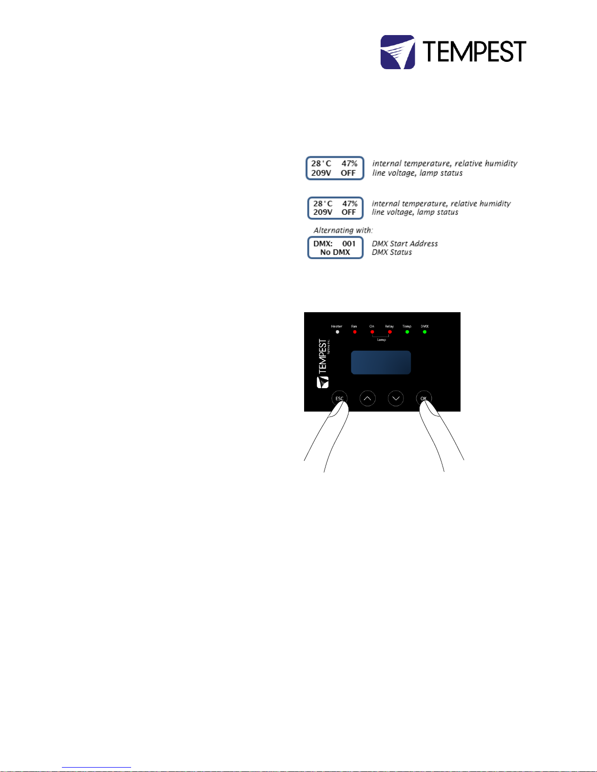
User Interface LCD Display ............................................................................................................................................................... 29
Control Interface Operation ............................................................................................................................................................ 29
Control Menu ........................................................................................................................................................................................ 30
Set DMX Options .............................................................................................................................................................................. 30
Set Temp Units ................................................................................................................................................................................. 31
Set Temp Ranges .............................................................................................................................................................................. 31
Set Lamp On Point ............................................................................................................................................................................ 31
Reset Lamp Hours............................................................................................................................................................................. 31
Status Display .................................................................................................................................................................................... 32
Mounting the Luminaire ........................................................................................................................................................................... 33
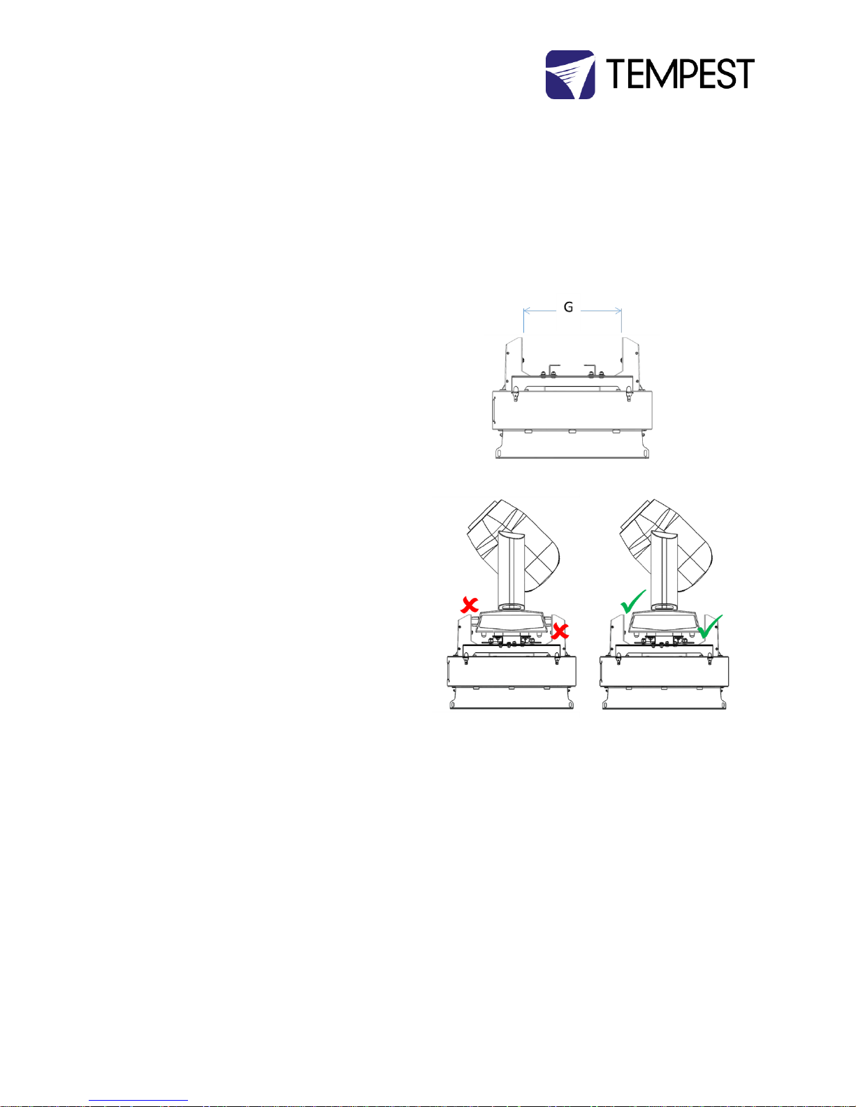
Luminaire Base Handles ....................................................................................................................................................................... 33
Mounting Bars ...................................................................................................................................................................................... 34
Mounting The Luminaire ...................................................................................................................................................................... 35
Omega Clamps .................................................................................................................................................................................. 36
Screws ............................................................................................................................................................................................... 37
Quarter-Turn Fasteners (QTF) ......................................................................................................................................................... 38
Install Luminaire in the Tornado Base ............................................................................................................................................. 39
Vari-Lite Truss Adapters ................................................................................................................................................................... 40
Connect Luminaire Power ................................................................................................................................................................ 41
Routine Maintenance ............................................................................................................................................................................... 42
Clean Acrylic Globe ........................................................................................................................................................................... 42
Check Filter ....................................................................................................................................................................................... 42
Check Temperature/Humidity Sensor ............................................................................................................................................. 43
For After Sales Support .................................................................................................................................................................... 43
Troubleshooting ........................................................................................................................................................................................ 44
Warranty ................................................................................................................................................................................................... 46
Appendix – TEMP Protocol ....................................................................................................................................................................... 47
Physical Layer ........................................................................................................................................................................................ 47
Developer’s Guide ................................................................................................................................................................................ 47
Page 4

Tornado G4 User Manual 4
Approvals – North America
This is to certify that the following products:
55.xxx.US Series Tornado G4 Luminaire Enclosures
Have been tested and approved to standards UL 508 (electrical) and UL 50 (environmental), as NEMA 3R enclosures,
for use in the United States and Canada.
This declaration is made by the manufacturer
Tempest Lighting, Inc.
11845 Wicks Street, Sun Valley, CA 91352, USA
This declaration is based on tests that were conducted on the submitted samples of the above mentioned products.
Listing Report No. 3198609LAX-001a refers.
Dated: July 1st , 2016
Signature . . . . . . . . . . . . . .
Tempest Lighting Inc
Page 5

Tornado G4 User Manual 5
Approvals – Europe
CERTIFICATE AND DEC L A R A T I O N O F C O N F O R MITY
FOR CE MARKING
Tempest Lighting, Inc .
11845 Wicks Stree t , S u n Valley, CA 91 3 5 2 , USA
t: +1 818 787 8 9 8 4 f: +1 818 252 7101 e: in f o @tempest.biz
www.tempest.biz
Tempest Lighting, Inc . declares that t heir
Tornado G4 L u m in a i r e Enclosure Se ries 55.xx x . x x
complies with the E s s e ntial Requirements o f the following E U D irectives:
Low Voltage Dire c t i v e 2006/95/EC Test Repo r t G4.51.LVD
Electromagnetic Co m p a t ibi l ity Directive 2 0 04/108/EC Test Report G 4 . 5 1.EMC
and further conform s w ith the follo wing EU Ha r m onized Standards:
EN 60065 : 20 0 2 Te s t Report 60065.G4.5 1 . 01
EN 60529:2001 -2002 Test Report 60 5 2 9 .G4.51.02
EN 61000-6 - 3 : 20 07+A1:2011 Test Repo r t 61000.G4.51 . 03
EN61000-6-1 : 2 0 0 7 Te s t Report 61000.G4.5 1 . 03
EN55015:2006+ A2 :2009 Test R e p o rt 61000.G4.51.0 3
Dated: 1
s t
July 2016
Position of signato r y : President
Na me of Signatory: T i m Burnham
Signe d below:
on behalf of Tempes t L ighting, Inc.
. . . . . . . . . . . . . . . . . . . . . . . . . . . . .
Page 6
Tornado G4 User Manual 6
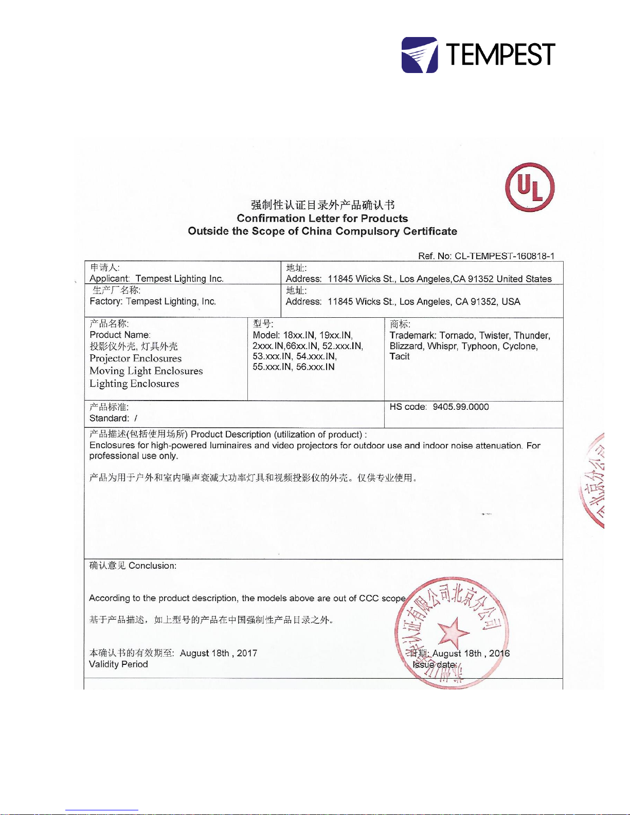
Approvals – China
Page 7

Tornado G4 User Manual 7
Introduction
Thank you for purchasing a Tempest enclosure! We have worked hard to provide you with the very
best product available for its purpose, and we shall continue to do everything possible to ensure that
it works well for you for many years to come.
Please read this manual before starting work!
In the event of difficulty, please contact your Tempest reseller or Tempest direct:
+1 818 787 8984
We will do everything we can to help you get the very best results from your Tempest enclosure.
IMPORTANT: Safety Advisories
All installation and rigging work done must where applicable be designed and built in
accordance with norms and standards of the local authority having jurisdiction of the
installation site. It is the responsibility of the installer to obtain such approvals as may be
required to achieve full compliance.
All electrical work must be carried out by a suitably licensed electrical contractor in full
compliance with local electrical standards.
Lifting: some enclosures and the equipment inside them may be heavy. Use properly rated
lifting equipment where appropriate and never attempt to carry out work with fewer than
the number of workers needed to lift safely.
It is the responsibility of the installer to ensure that all local building, safety and electrical
codes are strictly adhered to in the installation of this enclosure. Tempest Lighting, Inc., its
employees and agents are in no way responsible for damage arising from failure to follow
either the instructions in this manual or building, safety and electrical codes prevailing at
the installation location.
Do not attempt to install or operate the enclosure before fully reading and understanding
this manual
Never allow anyone who has not read this manual to open the enclosure or perform
maintenance on the luminaire within.
Never leave the enclosure unattended when open.
Always make sure all bolts and latches are tight and safety locks are in place after
performing any form of maintenance on the unit.
Do not open any electrical boxes until power has been shut off to all supply lines to the
enclosure (including the one powering the luminaire).
Do not open the enclosure in wet weather.
Page 8
Tornado G4 User Manual 8
Installation
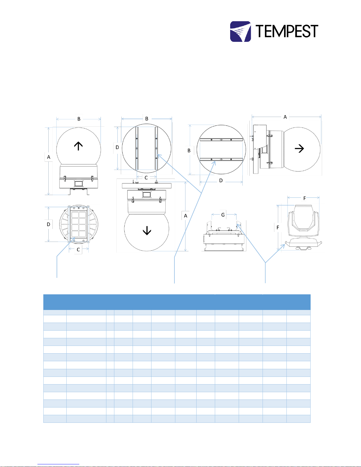
Dimensions, Rigging Points, and Maximum Luminaire Dimensions/Power
Model #
Description
A
Height
B
Diameter
C
Mounting
Centers
D
Mounting
Centers
Weight
Lbs/kg
E
Luminaire
Max Height
F
Luminaire
Max Width
G
Luminaire
Base Width
Luminaire
Max Watts
1850.xxG
Tornado 1850
32”/813
23”/584
11.95”/304
21”/533
42/19
16.5”/420
16”/410
14.5”/370
500W
1850.xxGV
Tornado 1850
33”/838
30”/762
11.95”/304
23”/584*
45/21
16.5”/420
16”/410
14.5”/370
500W
1850.xxGH
Tornado 1850
33”/838
30”/762
11.95”/304
23”/584*
46/21
16.5”/420
16”/410
14.5”/370
500W
1850.xxM
Tornado Marine 1850
33”/838
23”/584
11.95”/304
21”/533
42/19
16.5”/420
16”/410
14.5”/370
500W
1850.xxMV
Tornado Marine 1850
34”/864
30”/762
11.95”/304
23”/584*
45/21
16.5”/420
16”/410
14.5”/370
500W
1850.xxMH
Tornado Marine 1850
34”/864
30”/762
11.95”/304
23”/584*
46/21
16.5”/420
16”/410
14.5”/370
500W
1900.xxG
Tornado 1900
38”/965
24”/610
11.95”/304
21”/533
52/24
24.5”/620
16”/410
14.5”/370
600W
1900.xxGV
Tornado 1900
39”/991
30”/762
11.95”/304
23”/584*
60/27
24.5”/620
16”/410
14.5”/370
600W
1900.xxGH
Tornado 1900
39”/991
30”/762
11.95”/304
23”/584*
60/27
24.5”/620
16”/410
14.5”/370
600W
1900.xxM
Tornado Marine 1900
39”/991
24”/610
11.95”/304
23”/584*
52/24
24.5”/620
16”/410
14.5”/370
600W
1900.xxMV
Tornado Marine 1900
40”/1016
30”/762
11.95”/304
23”/584*
60/27
24.5”/620
16”/410
14.5”/370
600W
1900.xxMH
Tornado Marine 1900
40”/1016
30”/762
11.95”/304
23”/584*
60/27
24.5”/620
16”/410
14.5”/370
600W
1925.xxG
Tornado 1925
42”/1070
27”/690
11.95”/304
21”/533
52/24
28”/710
16”/410
14.5”/370
600W
1925.xxGV
Tornado 1925
43”/1090
30”/762
11.95”/304
23”/584*
60/27
28”/710
16”/410
14.5”/370
600W
1925.xxGH
Tornado 1925
43”/1090
30”/762
11.95”/304
23”/584*
60/27
28”/710
16”/410
14.4”/370
600W
Rigging Points – Globe Up:
Use M12 stainless steel bolts (supplied with
shipping pallet) to attach to structure
Rigging Points – Globe Down/Horizontal:
Use M12 stainless steel bolts and Spring
Nuts (supplied with shipping pallet) to
attach Unistrut rails to structure
Base Width (G): It may be
necessary to remove base
handles for some
luminaires.
Page 9

Tornado G4 User Manual 9
Model #
Description
A
Height
B
Diameter
C
Mounting
Centers
D
Mounting
Centers
Weight
Lbs/kg
E
Luminaire
Max Height
F
Luminaire
Max Width
G
Luminaire
Base Width
Luminaire
Max Watts
1925.xxM
Tornado Marine 1925
43”/1090
27”/690
11.95”/304
21”/533
52/24
28”/710
16”/410
14.5”/370
600W
1925.xxMV
Tornado Marine 1925
44”/1118
30”/762
11.95”/304
23”/584*
60/27
28”/710
16”/410
14.5”/370
600W
1925.xxMH
Tornado Marine 1925
44”/1118
30”/762
11.95”/304
23”/584*
60/27
28”/710
16”/410
14.5”/370
600W
1975.xxG
Tornado 1975
45”/1150
27”/690
11.95”/304
21”/533
57/26
30.5”/780
16”/410
14.5”/370
600W
1975.xxGV
Tornado 1975
46”/1168
30”/762
11.95”/304
23”/584*
65/30
30.5”/780
16”/410
14.5”/370
600W
1975.xxGH
Tornado 1975
46”/1168
30”/762
11.95”/304
23”/584*
65/30
30.5”/780
16”/410
14.5”/370
600W
1975.xxM
Tornado Marine 1975
46”/1168
23”/584
11.95”/304
21”/533
57/26
30.5”/780
16”/410
14.5”/370
600W
1975.xxMV
Tornado Marine 1975
47”/1194
30”/762
11.95”/304
23”/584*
65/30
30.5”/780
16”/410
14.5”/370
600W
1975.xxMH
Tornado Marine 1975
47”/1194
30”/762
11.95”/304
23”/584*
65/30
30.5”/780
16”/410
14.5”/370
600W
2000.xxG
Tornado 2000
45”/1150
32”/820
16.23”/412
28.5”/724
110/50
30.5”/780
21”/530
19.25”/490
1200W
2000.xxGV
Tornado 2000
39”/991
36”/914
16.23”/412
30”/762*
115/55
30.5”/780
21”/530
19.25”/490
1200W
2000.xxGH
Tornado 2000
39”/991
36”/914
16.23”/412
30”/762*
115/55
30.5”/780
21”/530
19.25”/490
1200W
2000.xxM
Tornado Marine 2000
39”/991
32”/820
16.23”/412
28.5”/724
110/50
30.5”/780
21”/530
19.25”/490
1200W
2000.xxMV
Tornado Marine 2000
40”/1016
36”/914
16.23”/412
30”/762*
115/55
30.5”/780
21”/530
19.25”/490
1200W
2000.xxMH
Tornado Marine 2000
40”/1016
36”/914
16.23”/412
30”/762*
115/55
30.5”/780
21”/530
19.25”/490
1200W
2300.xxG
Tornado 2300
53”/1350
36”/914
16.23”/412
28.5”/724
111/51
38”/970
21”/530
19.25”/490
1700W
2300.xxGV
Tornado 2300
54”/1370
36”/914
16.23”/412
30”/762*
126/57
38”/970
21”/530
19.25”/490
1700W
2300.xxGH
Tornado 2300
54”/1370
36”/914
16.23”/412
30”/762*
126/57
38”/970
21”/530
19.25”/490
1700W
2360.xxG
Tornado 2360
53”/1350
36”/914
16.23”/412
28.5”/724
111/51
38”/970
VL6000-specific
2360.xxGV
Tornado 2360
54”/1370
36”/914
16.23”/412
30”/762*
126/57
38”/970
VL6000-specific
2360.xxGH
Tornado 2360
54”/1370
36”/914
16.23”/412
30”/762*
126/57
38”/970
VL6000-specific
2300.xxM
Tornado Marine 2300
54”/1370
36”/914
16.23”/412
28.5”/724
111/51
38”/970
21”/530
19.25”/490
1700W
2300.xxMV
Tornado Marine 2300
55”/1397
36”/914
16.23”/412
30”/762*
126/57
38”/970
21”/530
19.25”/490
1700W
2300.xxMH
Tornado Marine 2300
55”/1397
36”/914
16.23”/412
30”/762*
126/57
38”/970
21”/530
19.25”/490
1700W
2400.xxG
Tornado 2400
61”/1530
42”/1067
19.48”/495
34.50”/87
6
204/93
44”/1120
28”/710
24.25”/615
2500W
2400.xxGV
Tornado 2400
62”/1575
42”/1067
19.48”/495
36”/914*
209/95
44”/1120
28”/710
24.25”/615
2500W
2400.xxM
Tornado Marine 2400
61”/1530
42”/1067
19.48”/495
34.50”/87
6
204/93
44”/1120
28”/710
24.25”/615
2500W
2400.xxMV
Tornado Marine 2400
62”/1575
42”/1067
19.48”/495
36”/914*
209/95
44”/1120
28”/710
24.25”/615
2500W
2500.xxG
Tornado 2500
67”/1700
48”/1220
19.48”/495
34.50”/87
6
209/95
52”/1320
28”/710
24.25”/615
3000W
2500.xxGV
Tornado 2500
68”/1725
48”/1220
19.48”/495
36”/914*
214/97
52”/1320
28”/710
24.25”/615
3000W
2500.xxM
Tornado Marine 2500
67”/1700
48”/1220
19.48”/495
34.50”/87
6
209/95
52”/1320
28”/710
24.25”/615
3000W
2500.xxMV
Tornado Marine 2500
68”/1725
48”/1220
19.48”/495
36”/914*
214/97
52”/1320
28”/710
24.25”/615
3000W
Page 10
Tornado G4 User Manual 10
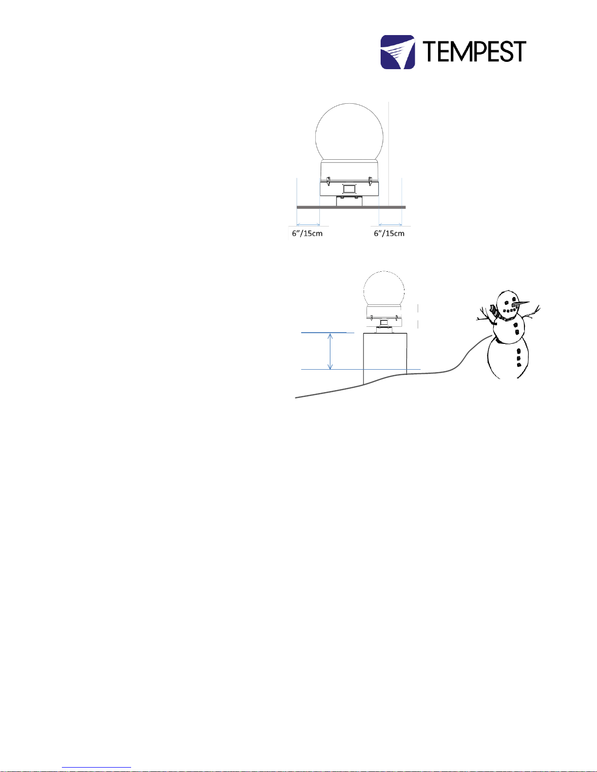
Airflow Clearance
Observe the minimum clearances shown around your
enclosure
Snow Clearance
In areas where snow is likely, make sure the base of the
enclosure is at least 24” [60cm] above highest potential
snow drift level.
60cm/24in
Page 11
Tornado G4 User Manual 11
Mounting Hardware Options
Mounting Bolts
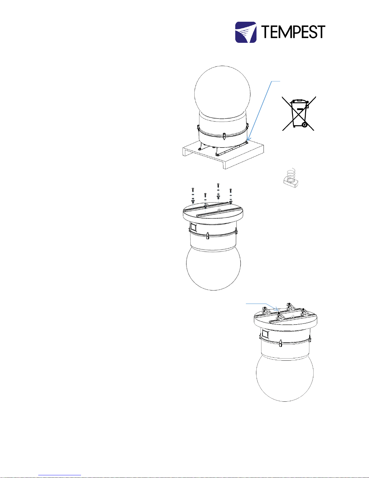
1. DO NOT DISCARD THE BOLTS ATTACHING THE
ENCLOSURE TO THE SHIPPING PALLET
2. Each Enclosure must be mounted with FOUR points.
3. Mountings must be made using M12 or ½” bolts
4. Tempest recommends the use of stainless steel
mounting hardware.
5. Bolt enclosure to a stable structure capable of
supporting the weight of the enclosure plus the
luminaire enclosed.
Globe Down Tornado Enclosures
6. Bolt the Tornado enclosure to a suitable overhead
structure using the bolts and Unistrut spring nuts
supplied
7. To hang from a lighting truss, use four hanging clamps
or half-couplers, bolted to Unistrut spring nuts
8. Screw the eyebolts supplied into the center threaded
holes in the Unistruts and secure to the overhead
structure or truss with a safety cable (not supplied)
rated for 5 x the total weight of the Tornado enclosure
plus luminaire.
Horizontal Tornado Enclosures
9. Bolt the Tornado enclosure to a suitable overhead
structure using the bolts and Unistrut spring nuts
supplied – see illustration (6).
IMPORTANT SAFETY NOTICE
Installer must ensure that all mounting points are secure
and conform to local safety regulations. Tempest Lighting
Inc. accepts no responsibility for damage or injury arising
from inappropriate or unsafe installation.
M12-1.75 x 40 bolts,
washers, nuts
DO NOT DISCARD!
NOTE:
Globe Down and
Horizontal enclosures
also supplied with
Unistrut Spring nuts.
Use the M12 bolts,
washers and Unistrut
spring nuts provided to
attach globe-down
Tornado enclosures to a
suitable overhead
support.
Attach hanging
clamps or half
couplers to the
Unistrut rails to
hang Tornado from
a lighting truss
Safety cable Eyebolts
Page 12
Tornado G4 User Manual 12
Drainage
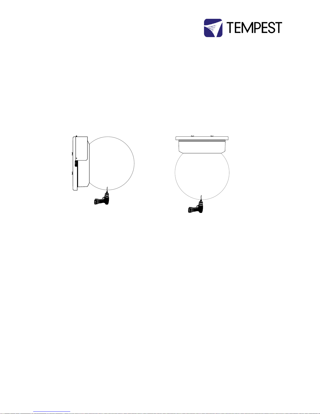
For base up/globe down or horizontal operation, a small drainage hole should be drilled in the globe, to permit any water
draining through the enclosure to exit harmlessly.
Note: this is not required in sheltered installations, such as under an overhang or canopy.
YOU MUST USE THE APPROPRIATE TAPERED DRILL BIT.
A tapered drill bit is included with the printed manual packet in each Tornado shipment.
Replacements are available from Tempest free of charge.
A standard drill bit may crack the plexiglass globe. Tempest Lighting will not be responsible for such damage.
Horizontal Enclosures – be sure to replace the globe with the drainage hole at the lowest point after relamping.
Page 13
Tornado G4 User Manual 13
Wiring the Enclosure
Power Wiring
SAFETY NOTICE
All power wiring must be performed by a competent electrician, appropriately licensed in the jurisdiction where the installation takes
place. All electrical work must be done in full compliance with all electrical and safety norms applicable to the installation site. Isolate
all power feeds before opening the enclosure.
Tempest Lighting, Inc., its employees and agents will not be held responsible for damage or injury caused by disregarding this notice.
Electrical Standards
Important:
Enclosure model numbers including .US are for use in countries using US and Japanese style electrical systems:
200-208VAC 50/60Hz
Enclosure model numbers including .IN are for use in countries using European style electrical systems:
220-250VAC 50/60Hz
Note:
(1) All Tornado and Tornado Marine G4 exhaust fans are 120VAC, regardless of electrical standard. The control electronics
provide a variable ac supply to the exhaust fans up to 120V.
(2) Heaters are rated 200-250V, dependent on electrical standard.
(3) Electronics are autosensing for any voltage 90-265VAC, 50/60Hz
(4) Tornado enclosures may be supplied wired for 120V operation to special order.
Wiring Access – Globe-up Models
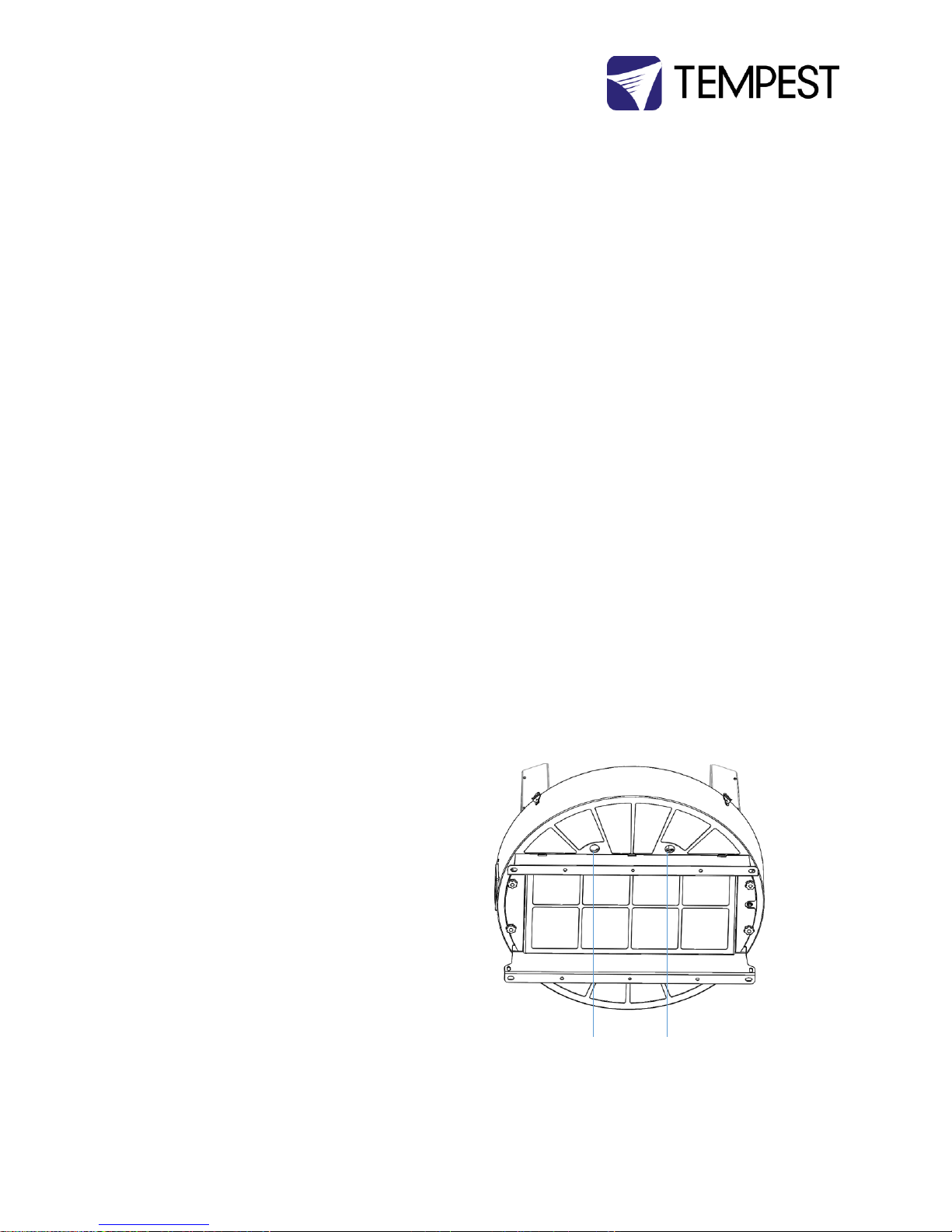
Locate the two Conduit entry holes on the underside of
the enclosure:
Conduit openings accept PG21 (International) and ¾” NPT
(North America) conduit fittings.
Use permanent or flexible, outdoor rated, conduit to
connect power and signal cables to your Tornado
enclosure.
ALWAYS RUN POWER AND SIGNAL CABLES IN SEPARATE
CONDUITS.
Conduit Entry:
SIGNAL
Conduit Entry:
AC POWER
Page 14
Tornado G4 User Manual 14
Wiring Access – Globe-down and
Horizontal Models
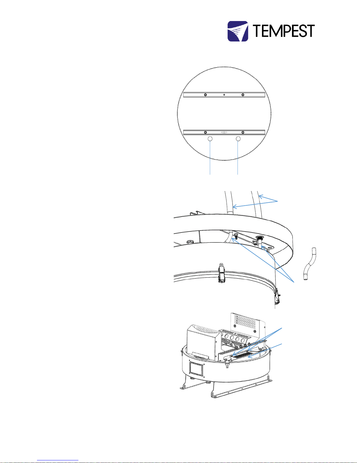
Locate the two Conduit entry holes on the enclosure rain
guard:
Conduit openings accept PG21 (International) and ¾” NPT
(North America) conduit fittings.
USE LIQUID-TIGHT CONDUIT FITTINGS OR CABLE GLANDS.
Use permanent or flexible, outdoor rated conduit to
connect power and signal cables to your Tornado
enclosure.
Use the plastic sleeves supplied to protect cables
between the conduit fittings and the internal wiring
terminals.
ALWAYS RUN POWER AND SIGNAL CABLES IN SEPARATE
CONDUITS.
Remove the DEC4 Controller cover.
Conduit Entry:
AC POWER
Conduit Entry:
SIGNAL
Cover
Thumbscrews
DEC4 Cover
Flexible Conduit
with watertight
fittings
Plastic Sleeve
Page 15
Tornado G4 User Manual 15
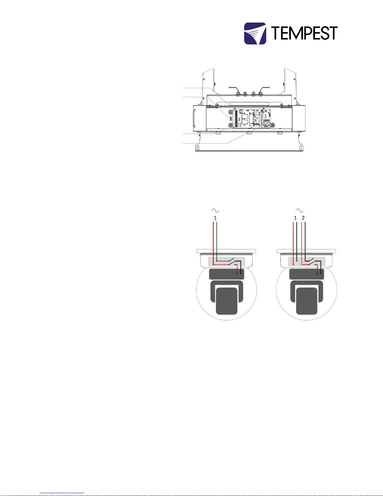
Identify the following parts:
AC Terminal Block
Earth/Ground Terminal
DEC4 Motherboard
DEC4 Daughter Board(s)
Up to 3 daughter boards: types include Fan Control,
RS485 Comms, Ethernet
(CUTAWAY VIEW)
One or Two Power Circuits?
Tempest enclosures may be wired on single or double
circuit supplies. On a single feed, both enclosure and
luminaire are permanently on. With a split (double) feed
supply, you can switch off the luminaire when not in use,
while the enclosure continues to protect it 24/7.
Tip: most people use single feed.
Tip: even wired for single feed, you can use DMX to switch
the luminaire power on and off – see the DEC4 section
below.
Single Feed
Enclosure and luminaire are permanently on.
Enclosure and Luminaire must be rated for the
same voltage.
Supply must be rated for luminaire current plus
150 watts.
Supply must be permanently ON.
Split feed
Enclosure power must be permanently ON.
Luminaire power may be switched off.
Enclosure power must be rated for:
o Tornado 1850-1975: 650 watts
o Tornado 2000-2300: 1150 watts
o Tornado 2400-2500: 2000 watts
Luminaire power must be rated for the luminaire (see
luminaire manual).
Single Feed
Split Feed
Page 16
Tornado G4 User Manual 16
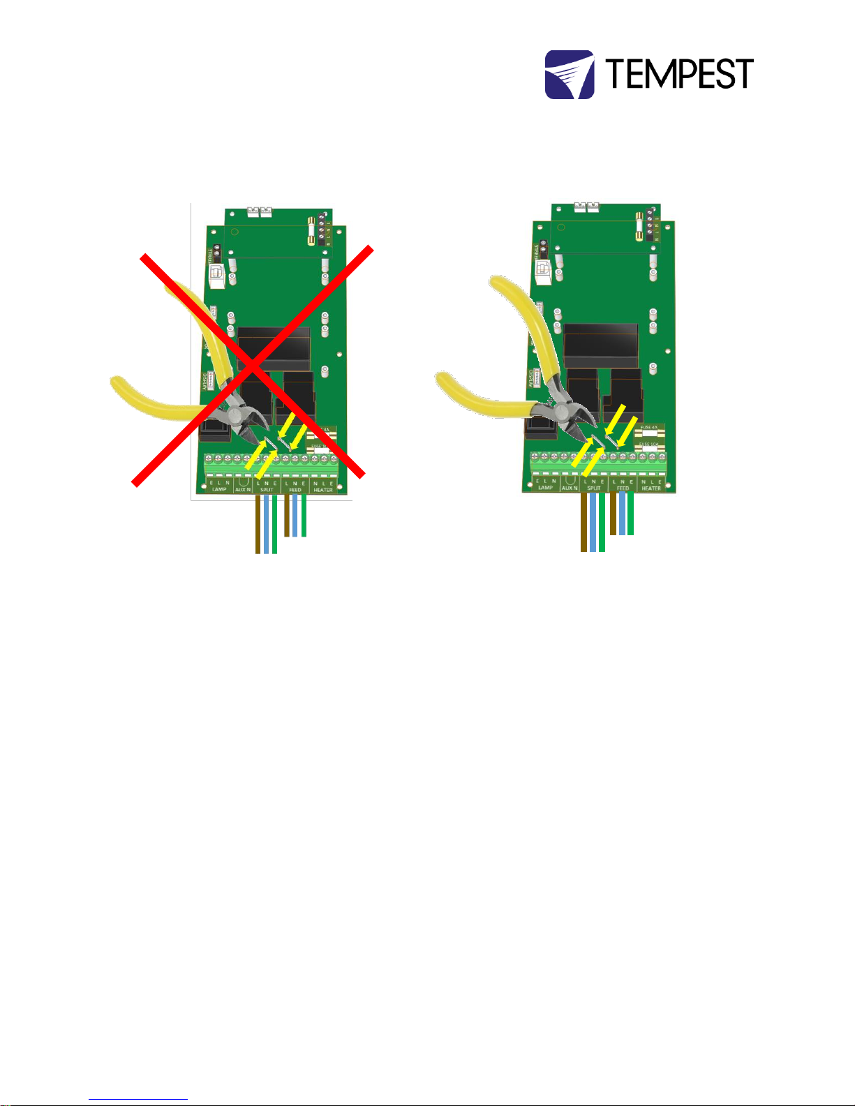
For single feed wiring, no modification to the DEC4
Controller motherboard is needed.
IMPORTANT:
For split feed wiring, use a side cutter to cut both AC links at both
ends:
Single Feed Power Termination
Connect Earth/Ground wire to Ground Terminal
Connect Live and Neutral to the terminals marked
FEED
Split Feed Power Termination
STOP! Did you cut the power links? See above.
Connect Earth/Ground wire to Ground Terminal
Connect Enclosure feed to the terminals marked FEED
Connect Luminaire feed to the terminals marked SPLIT
SEE WIRING DIAGRAMS BELOW
AC Supply Voltage
Tempest Tornado enclosures require supply voltage in
the nominal range 200-250VAC, 50/60Hz.
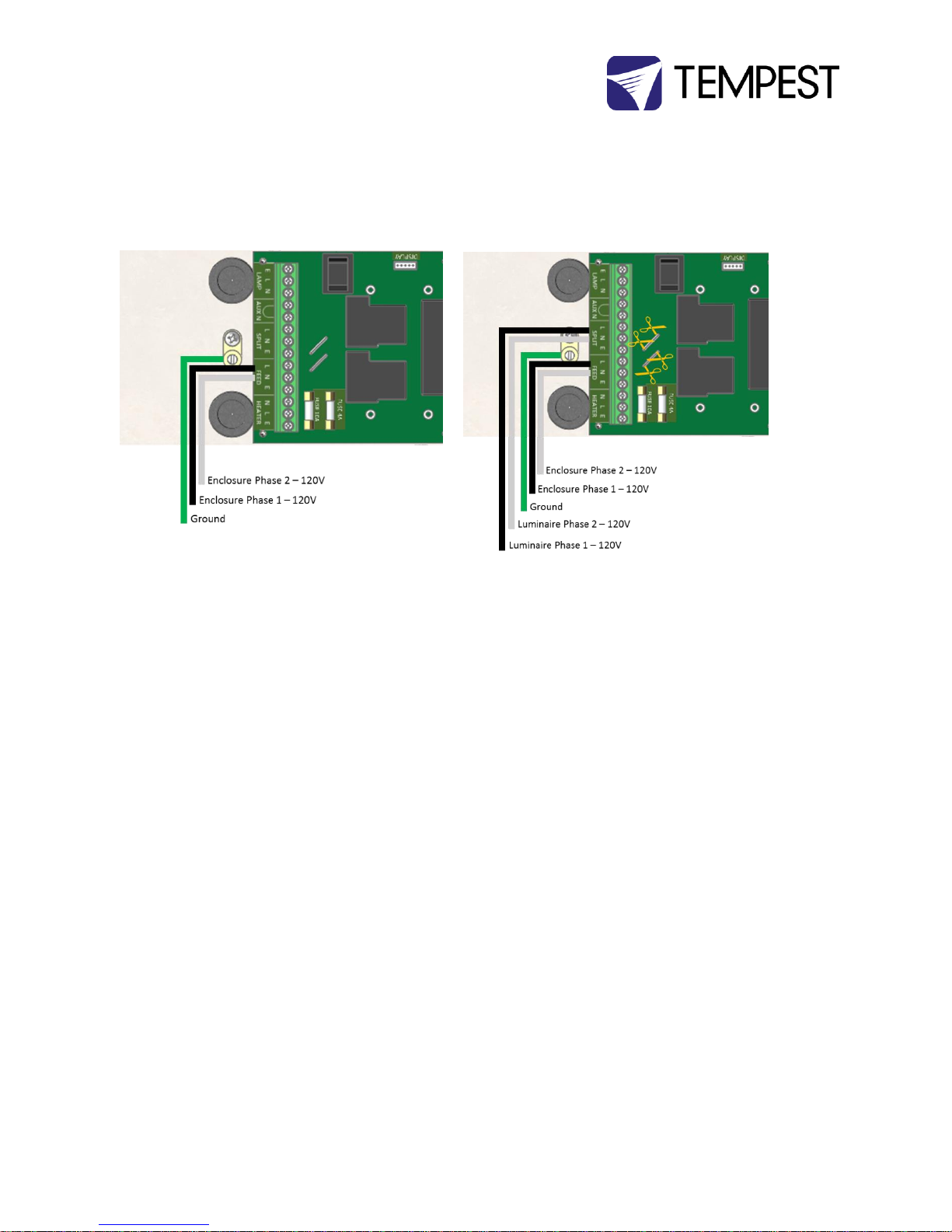
North American installations – use a 208V
supply (2 x 120V hots), and connect one hot to
Line and one to Neutral terminals.
North American 120V versions are available to
special order.
Page 17
Tornado G4 User Manual 17
Wiring – North America/Japan 200-208VAC
Note: For clarity, internal wiring is not shown.
Single Feed
Split Feed
Page 18
Tornado G4 User Manual 18
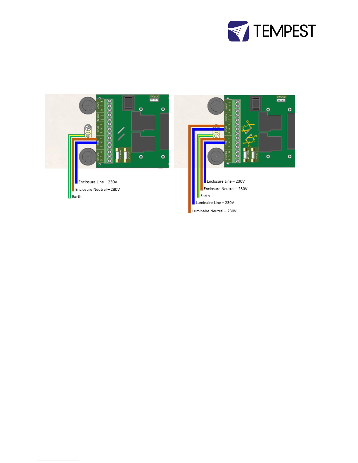
Wiring – International 220-250VAC
Note: For clarity, internal wiring is not shown.
Single Feed
Split Feed
Page 19

Tornado G4 User Manual 19
Remote Monitoring Connections
Tempest G4 enclosures optionally support four types of
remote monitoring:
1. Direct via Ethernet, using Tempest TEMP
protocol (see Appendix – TEMP Protocol)
Requires 51.EN Ethernet board
2. Grouped via RS485, using an Ethernet bridge and
Tempest TEMP protocol (see Appendix – TEMP
Protocol)
Requires one 51.485 RS485 board per enclosure
and one 51.EN Ethernet board per bridge
3. Grouped via RS485, using DMX/RDM – see next
page
Requires one 51.485 RS485 board per enclosure,
and one JESE RDM-TRI Interface
Page 20
Tornado G4 User Manual 20
Direct Ethernet Monitoring Network
See Appendix for TEMP protocol programming information.
Page 21
Tornado G4 User Manual 21
RS485 to Ethernet TEMP Monitoring Network
See Appendix for TEMP protocol programming information.
Page 22
Tornado G4 User Manual 22
DMX/RDM Monitoring Network
Note: Tempest System Manager and web-based monitoring will be available early 2017
The 2000.195 JESE RDM-TRI MK2 passes
DMX information from a show control
system to each DEC4 controller.
Set a DMX address for each controller in the
range 1-510. See DEC4 section below for
more information.
Page 23
Tornado G4 User Manual 23
RS485 (DMX/RDM) Cable Terminations
Loop a shielded twisted pair cable (eg Belden 9841, though
many people now use a CAT5e cable) from the
control/monitoring point, around all enclosures.
Maximum total cable length is 1,200M (4,000ft). For longer
runs and wildly distributed systems, use a DMX/RDM
splitter (make sure that it supports RDM) and multiple
cable runs.
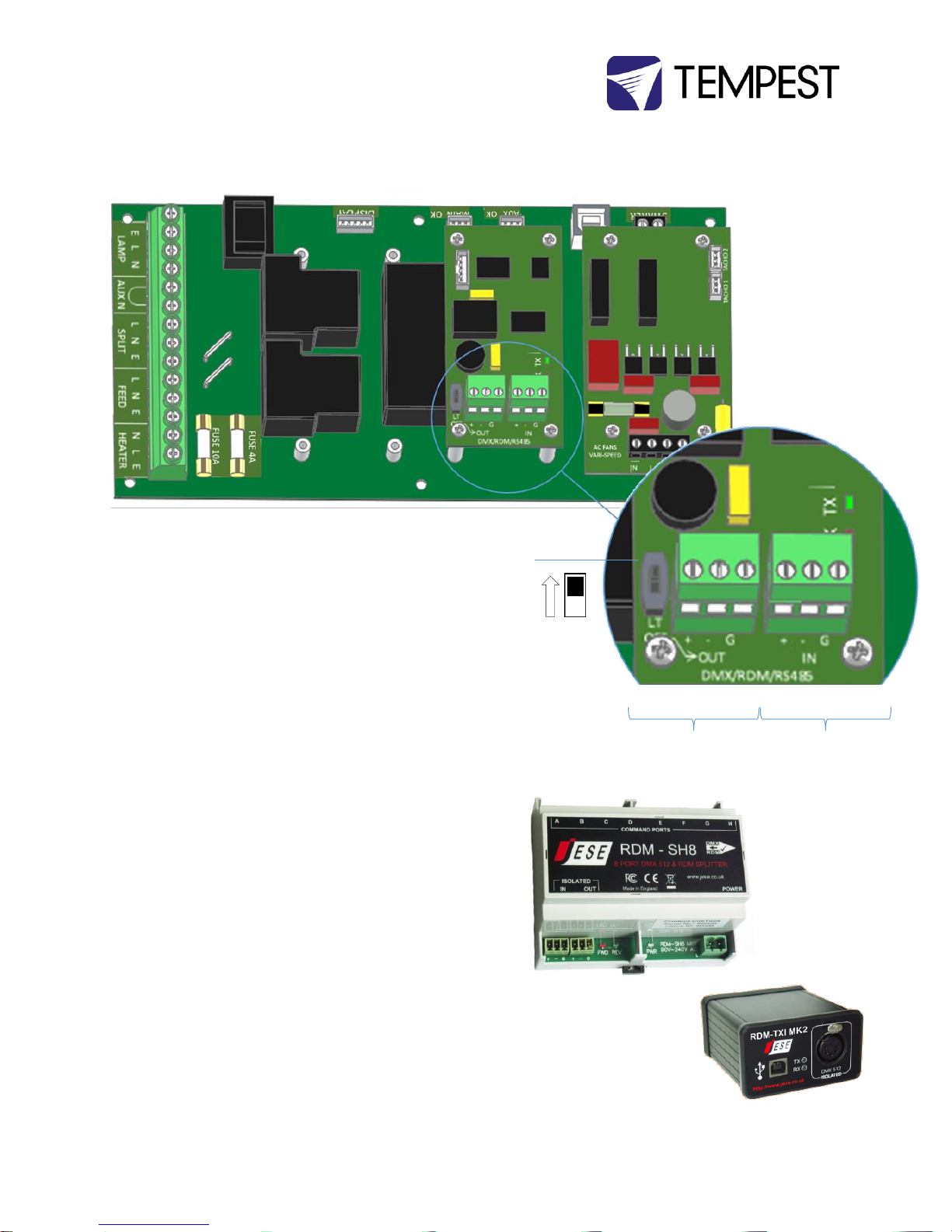
Use the termination switch to terminate each RS485 cable
run at the last enclosure on each run.
Luminaire Power Control using DMX512
The DEC4 controller includes a 30A 2-pole relay that
protects the enclosed equipment in the event of a serious
high temperature event by cutting off power.
You may use DMX512 to control power to the luminaire
inside the enclosure. This is very useful in hot locations,
where the luminaire may be stressed by being held in
standby mode all day under hot sun. By powering the
luminaire down it will tolerate much higher temperatures
without harm.
Tempest recommends the JESE RDM-TRI interface to
monitor enclosure status in any installation and control the
enclosure power relay in smaller systems.
More complex installations are very likely to include some
kind of show control system that will certainly include DMX
control. This is the preferred method of controlling power
to the luminaires.
JESE RDM-TRI interface connects to
a PC via USB to monitor and control
a network of Tempest enclosures.
Tempest Item # 2000.195
RS485 Line
Termination
(LT) Switch:
TERMINATED
Data + Data - Common Data + Data - Common
DATA OUT DATA IN
Tempest recommends
the JESE SH8 DMX/RDM
Splitter for large or
complex RS485
networks.
Page 24
Tornado G4 User Manual 24
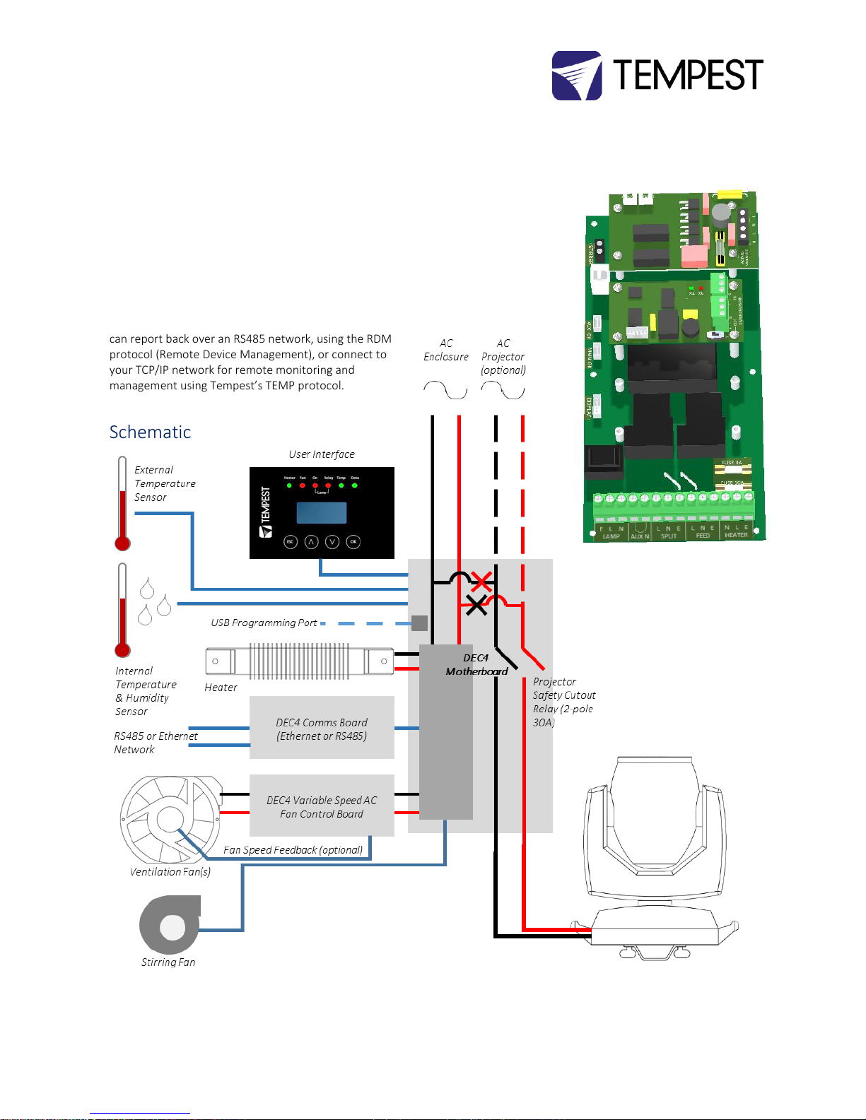
Digital Enclosure Control
DEC4TM – that’s Digital Enclosure Control, fourth
Generation – is the brain of your Tempest enclosure. It will
maintain the internal environment in a comfortable
temperature and humidity range, and prevent
condensation – the real killer of outdoor equipment. DEC4
monitors internal and external temperature, humidity and
lamp current at all times, and uses this information to
control the enclosure’s lamp relay, fan(s) and heater(s). It
can report back over an RS485 network, using the RDM
protocol (Remote Device Management), or connect to
your TCP/IP network for remote monitoring and
management using Tempest’s TEMP protocol.
Schematic
Typical DEC4
configuration, with
Motherboard, fan
control board and
RS485 comms
board
Page 25
Tornado G4 User Manual 25
DEC4 Main Functions
1. Sense current to luminaire (lamp on/off)
2. Record lamp hours
3. Monitor temperature and humidity inside
Enclosure
4. Monitor temperature outside enclosure
5. Maintain internal temperature at safe operating
level
6. Maintain relative humidity within safe limits to
prevent condensation
7. Isolate luminaire in case of unsafe temperature
8. Report status over RS485, RDM, TCP/IP
9. Maintain positive pressure (optional) 24/7 to
prevent ingress of salt air and other
contaminants
10. Circulates air internally to prevent hot and cold
spots when luminaire is idle
DEC3.3 constantly monitors the following parameters:
Luminaire/Luminaire current
Line Voltage
Temperature
Humidity
DEC 3.3’s patented GoldilocksTM algorithm uses a combination
of sensors, heaters and fans to maintain a safe operating
temperature and a safe relative humidity level that will not
allow condensation to take place.
As air is heated it is able to support more moisture without
condensing, so Goldilocks uses heat to raise the air temperature
inside the enclosure in the event that relative humidity
approaches dewpoint.
Factory Settings – Basic Mode
In most applications, DEC3.3 will operate correctly with its
factory default settings, in Basic operating mode.
You do not need to do anything. Please skip to the Power
Connections section below.
Standard default temperature and humidity settings
DMX, RDM and Remote Monitoring disabled
Best for standalone operation
Supports TEMP remote monitoring – see appendix
If your needs are more complex, read on.
Page 26

Tornado G4 User Manual 26
Other Operating Modes
Monitor Mode
As Basic mode, plus:
• RDM status reporting over RS485
• RDM configuration – settings may be changed remotely or at
the enclosure control panel
Control Mode
As Basic mode, plus:
Enclosure functions as a 1-channel DMX device, with
remote control of the lamp relay
o DMX level > 75% enables normal relay operation
(normally ON)
o DMX level < 25% disables normal relay operation
(relay turns OFF)
o This allows you to force a hard reset of the lamp relay
in the event of a luminaire malfunction
Control mode is recommended for show control
applications, but can be risky in live show operation, since
the DMX slot used for the enclosure MUST be kept high to
prevent the lamp relay from opening.
Service Mode
For trained service personnel only
Normal operation is suspended and the enclosure
functions as a 3-channel DMX device:
o Lamp Relay (Slot 1)
o Fans (Slot 2)
o Heater (Slot 3)
Service mode is ONLY for troubleshooting – DO NOT use
Service mode for normal operation.
Page 27
Tornado G4 User Manual 27
DEC4 Control Parameters
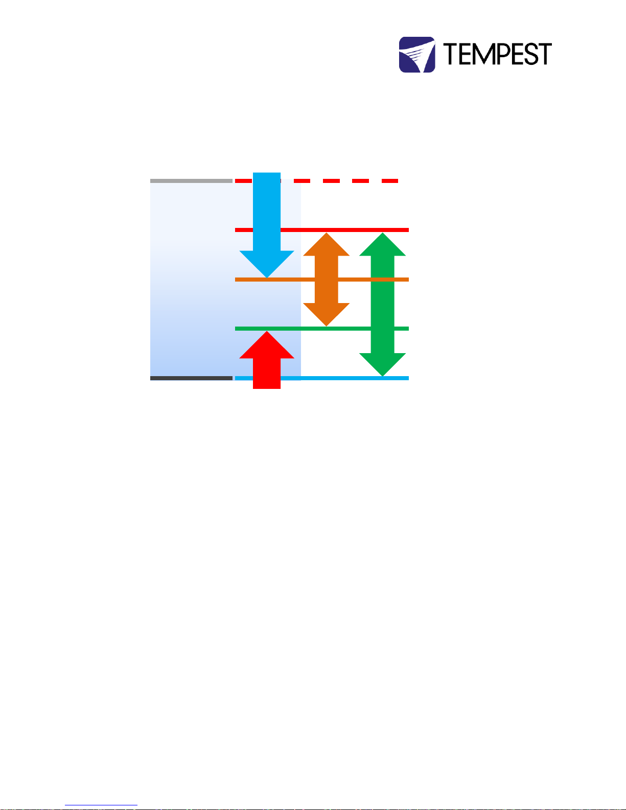
Temperature and Humidity Ranges
Notes:
1 In moving light enclosures the temperature sensor is located in the exhaust airflow. Temperatures
shown may be higher than those around the luminaire.
2 We recommend using the factory default settings for several weeks or months before making any
changes. In most cases they will not be necessary.
Trip Temp
(55-70˚C, Default 60 ˚C)
Upper Temp
(35-50˚C, Default 40 ˚C)
Trend Temp
(Dynamic)
IdealTemp (Dynamic, based
on Relative Humidity)
LowerTemp
(0-10˚C, Default 0 ˚C)
Cooling Fan(s)
Heater(s)
Relative Humidity
(50-90%,
Default 80%)
Low
High
Page 28
Tornado G4 User Manual 28
Control Interface
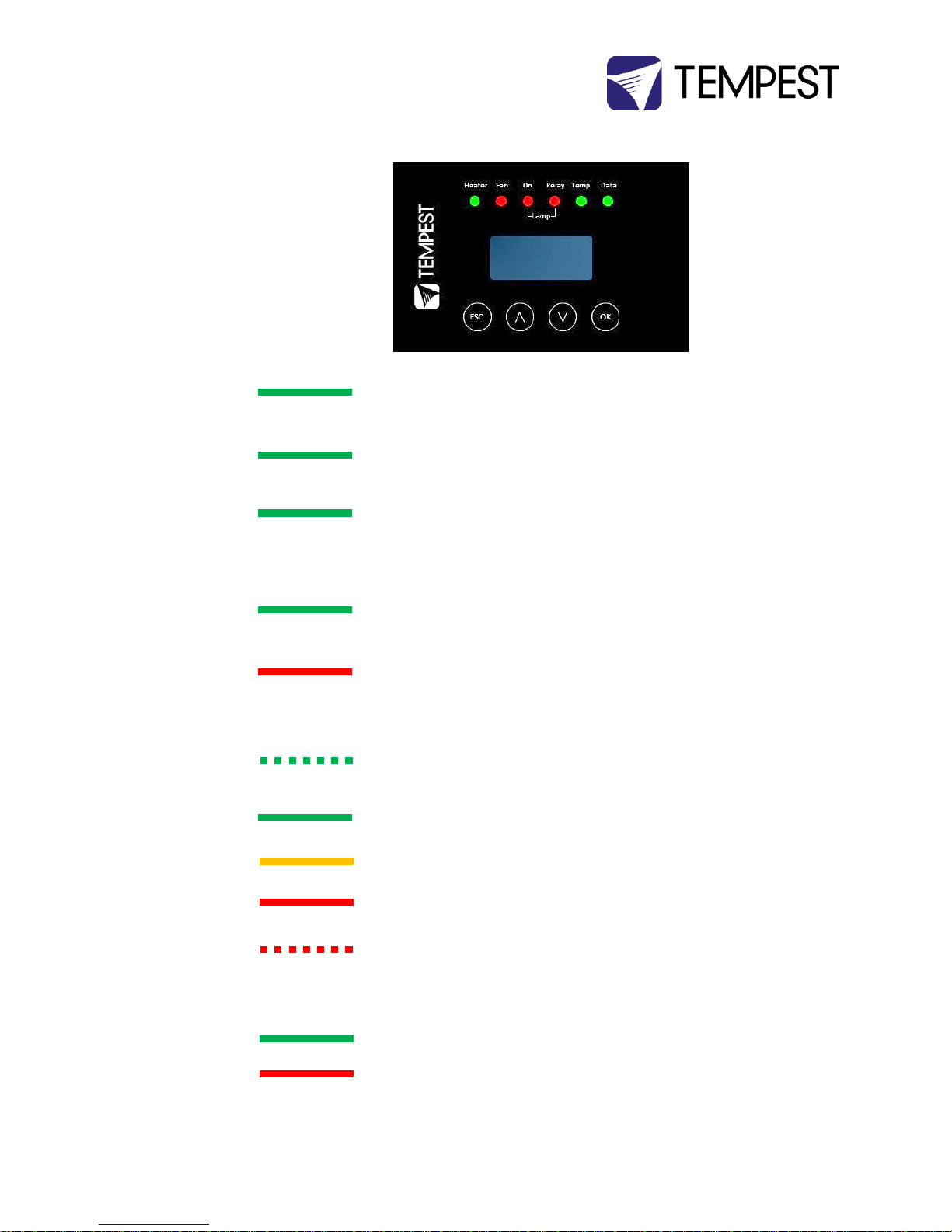
LED Indicators
Heater
ON (Green)
Heater is ON, to maintain lower temperature level or to prevent
condensation
Fan
ON (Green)
Lamp is ON, or Temperature is HIGH and
Fan is cooling enclosure. Short burst when lamp off indicates fan moving air
to stabilize temp/humidity
Lamp On
ON (Green)
Current sensing shows lamp is ON
Lamp hour counter is running
OFF
Current sensing shows lamp is OFF
Lamp hour counter is not running
Lamp Relay
ON (Green)
Lamp relay is closed (normal)
Luminaire power receptacle is energized
ON (Red)
Lamp relay is open due to over-temperature event. Luminaire power
receptacle is isolated.
Temp
FLASHING
(Green)
Temperature is below lower temp setting
ON (Green)
Temperature is in normal range
ON (Amber)
Humidity is above target limit
ON (Red)
Temperature is above top setting
FLASHING (Red)
Temperature is above Trip level
Luminaire power is isolated
Data
OFF
DEC4 is in BASIC Mode – Data not used. OR DEC4 is in TEMP, Monitor or
Control Mode and no valid data packet has been detected.
ON (GREEN)
Good data packet received.
ON (RED)
Control Mode: Data Fail. A previously good data signal has failed.
Monitor Mode: No RDM information being received (this is normal)
Page 29
Tornado G4 User Manual 29
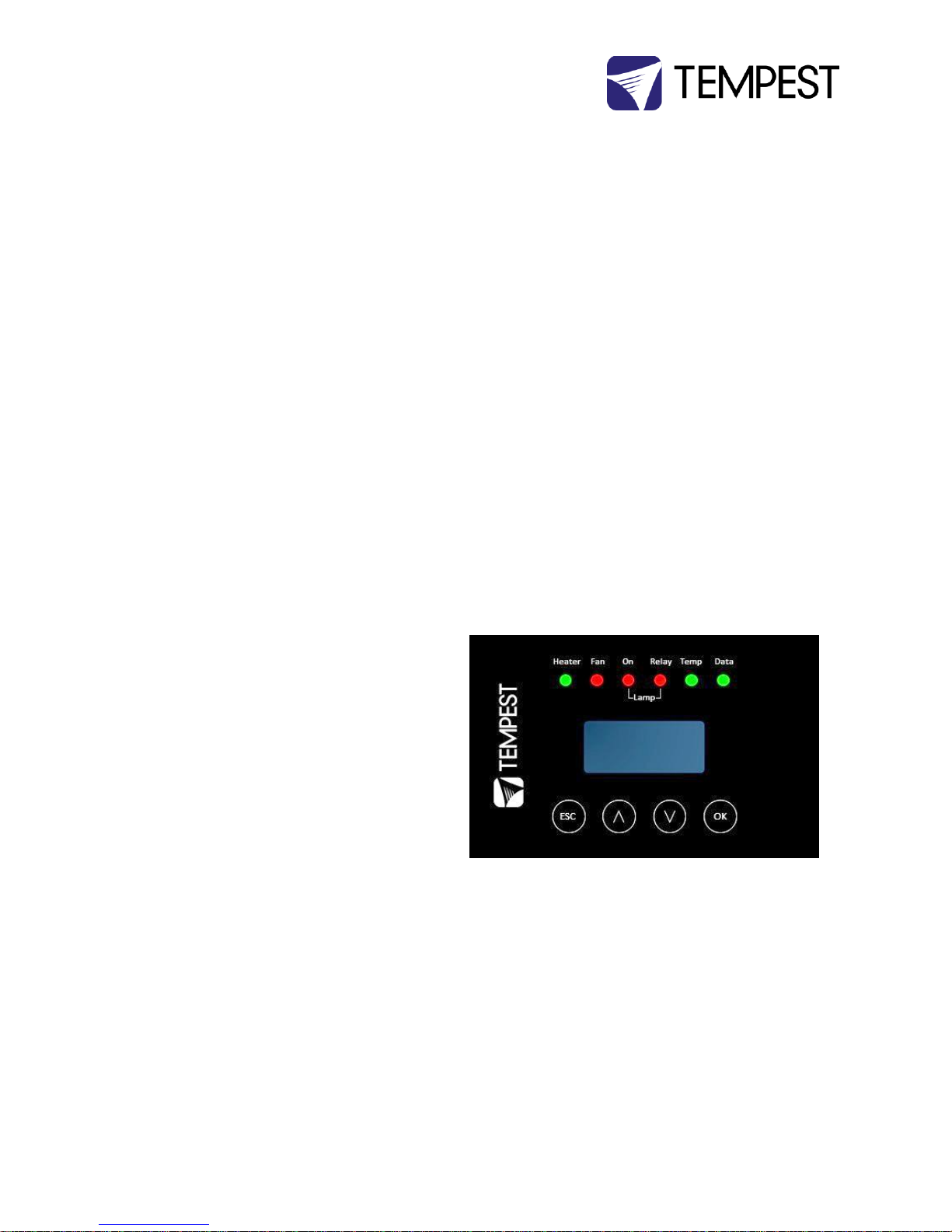
User Interface LCD Display
The display on the Control display provides additional status
information, depending on the operating mode:
Basic Mode & Monitor Mode
DMX Mode & Service Mode
Control Interface Operation
The Control Interface is normally LOCKED.
To UNLOCK, hold ESC and OK together for 5 seconds.
You are now in the CONTROL MENU
Use to scroll up and down the menu.
Press OK to enter a menu item
Use to set the item parameter, or to scroll to the
next menu level.
Use ESC to go BACK, or OK to confirm settings ( ).
To LOCK, hold ESC for 5 seconds.
Menu will time out after ten minutes.
Page 30

Tornado G4 User Manual 30
Control Menu
Set DMX Options
SET DMX MODE
From the Front Panel, this menu item allows the user to check (and if necessary change) the RDM mode.
BASIC Standalone operation, no DMX/RDM (factory default)
MONITOR Standalone, plus support for RDM remote configuration and monitoring
CONTROL Monitor, plus use of a single DMX slot to control Lamp relay
TEMP Same as Basic, but supports remote monitoring over RS485 with Ethernet adapter and Tempest
TEMP protocol
SERVICE Monitor, plus use of three DMX slots to control Lamp, Heater and Fan
Important: Please ensure that the DEC3.3 is NOT left in Service Mode.
SET DMX ADDRESS (in Monitor, Control or Service modes)
Select a DMX starting address in the range 001 to 510
1 – Lamp Relay
In Service Mode an addition two slots are available
2 – Fan Duty Control
3 – Heater Duty Control
Note that the DMX control is designed using a SAFETY pile-on Logic. So the DMX input can only override automatic
settings within safe limits.
SET DMX CURVE
DMX Curves affect the way the fixture relay is controlled in Control Mode.
DMX levels are shown as %.
Response Curve 1 (default)
DMX level 0-25 Relay disabled (open)
DMX level 26-75 No change to relay status
DMX level 76-100 Relay enabled (normally closed)
Response Curve 2
DMX level 0-19 No change to relay status
DMX level 20-40 Relay disabled (open)
Page 31

Tornado G4 User Manual 31
DMX level 41-59 No change to relay status
DMX level 60-80 Relay enabled (normally closed)
DMX level 81-100 No change to relay status
SET DMX RESPONSE
DMX Response sets a delay time before DMX Control Mode settings are acted on. Setting a response delay of a few
seconds would prevent unintended fixture relay state changes in the event of a short accidental change in DMX
level.
NOTE: from firmware revision 0.00.100, DEC holds last valid DMX level if DMX is interrupted.
Response Delay Values are:
No Delay (default), 1, 2, 5, 10, 15, 20, 30, 60 seconds.
Set Temp Units
Choose to display temperature values in Celsius or Fahrenheit (default Celsius)
Note that temperature settings must be entered in Celsius.
Set Temp Ranges
Set three temperature trigger points for Bottom, Top and Trip temperatures, in °C.
SET TEMP LOWER (minimum temperature to be maintained)
(default 0°C, permissible range 0-10°C).
SET TEMP UPPER (maximum desired temperature)
(default 40°C, permissible range 35-50°C).
SET TEMP TRIP (temperature at which load will be isolated – see note)
(default 60°C, permissible range 55-70°C).
SET DELTA T (target difference between outside and inside temperature – drives fan speed)
(default ON (constant 100% fan speed), permissible range 2-10°C).
Note: A thermal emergency is when enclosure ventilation fails with the lamp on, in which case the temperature will
rise very quickly. To avoid nuisance tripping we recommend setting a higher Trip temperature, 60°C or above.
Set Lamp On Point
The lamp current at which DEC detects the luminaire/luminaire lamp is running. Default is 1 Amp, which allows for
equipment fans and power supplies to run without changing the air in the enclosure. Lamp on point may be set in
0.2 Amp increments between 0.2 Amps and 2.0 Amps.
Reset Lamp Hours
Reset each time you change the lamp in the luminaire.
Make this a part of your maintenance instructions.
Page 32

Tornado G4 User Manual 32
Status Display
View current status information, using the arrow keys to scroll through:
a) Humidity – relative humidity in %
b) Air temperature, in degrees C or F
c) PCB temperature (this will usually be significantly higher than air temperature)
d) Voltage – line Voltage reaching the DEC
e) Current being drawn by luminaire/light, in Amps
f) Lamp Hours elapsed since last reset
g) Firmware version
Page 33
Tornado G4 User Manual 33
Mounting the Luminaire
Luminaire Base Handles
The distance between the fan/heater chimneys is limited.
Dimension G:
Tornado 1850-1975 14.5”/370mm
Tornado 2000-2300 19.25/490mm
Tornado 2400-2500 24.25”/615mm
In some cases, it will be necessary to remove the handles
from the luminaire base to fit it between the chimneys.
Follow the luminaire manufacturer’s service instructions to
remove the base handles before installing the luminaire.
Page 34
Tornado G4 User Manual 34
Mounting Bars
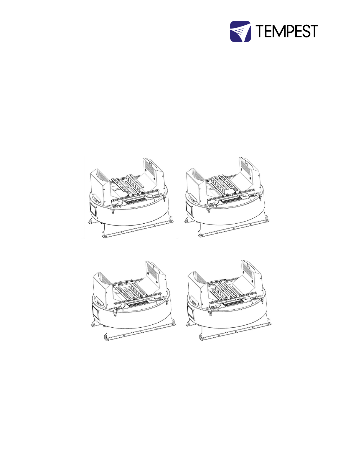
Tornado’s luminaire mounting system is extremely flexible.
Its stainless steel construction resists corrosion in any
environment and is very robust.
The mounting bars may be configured in four different
ways, depending on the luminaire size and chosen
mounting method (see below).
Luminaire Bars
High, Wide
Luminaire Bars
High, Narrow
Luminaire Bars
Low, Wide
Luminaire Bars
Low, Narrow
Page 35
Tornado G4 User Manual 35
Mounting The Luminaire
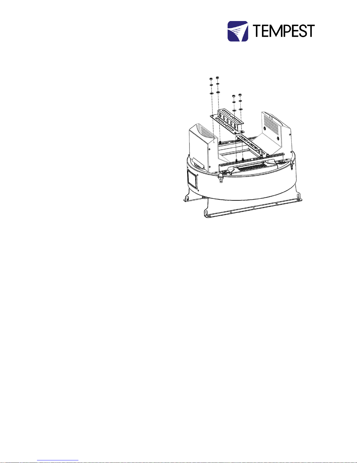
Moving lights from different manufacturers come with
various different mounting options, all of which will install
readily to Tornado’s luminaire mounts.
1. To mount the luminaire, first remove the two
mounting bars, by removing the 8mm nuts and
carriage bolts.
2. Choose the mounting method below:
Page 36
Tornado G4 User Manual 36
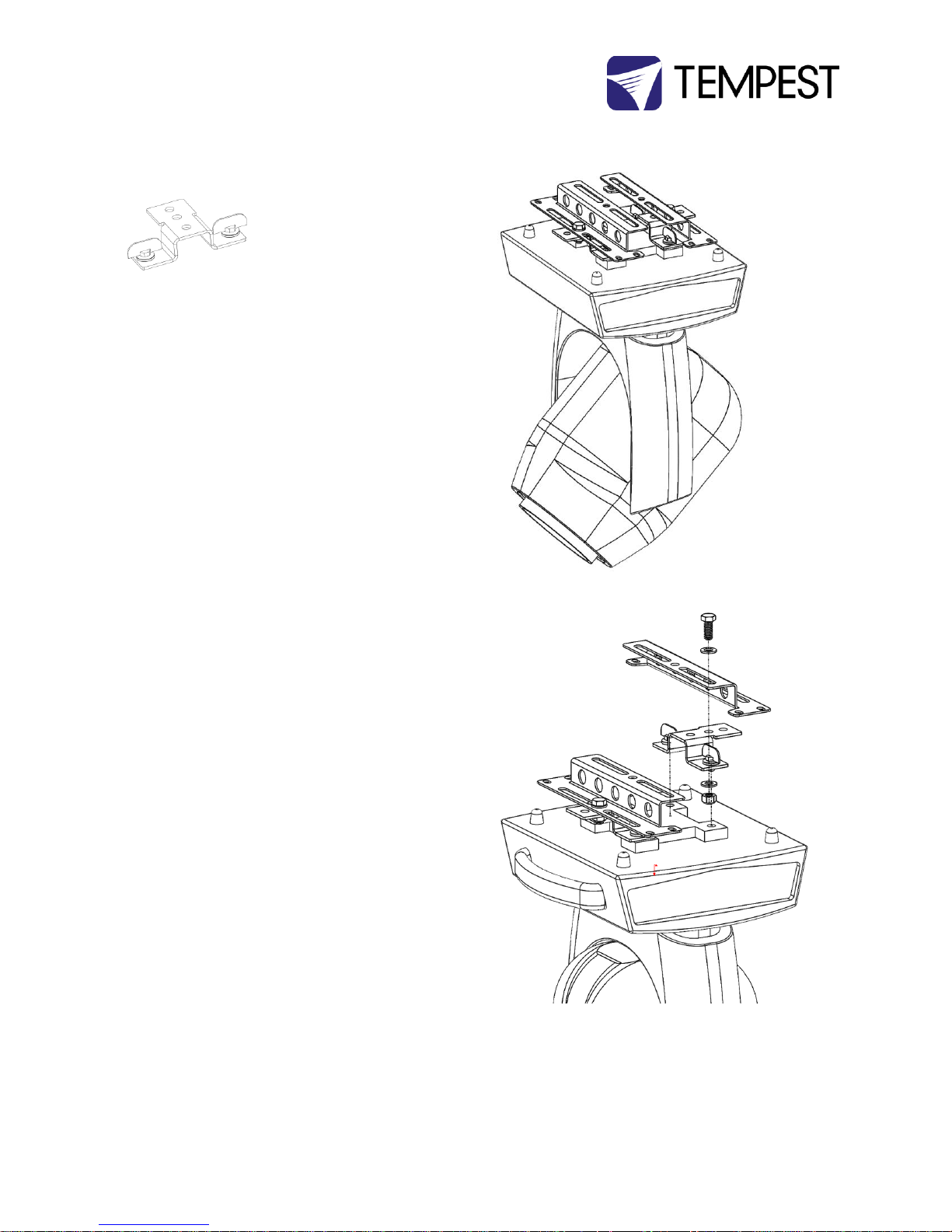
Omega Clamps
Most luminaires come with omega clamps of some kind,
and this is the easiest mounting method.
1. Simply bolt the omega clamp to the two luminaire
mounting bars. Note: This will probably work best in
one of the LOW positions (shown here), due to the
height of the omega brackets.
2. Check that the luminaire is centered and that the
ends of the mounting bars are parallel.
NOTE: In some cases, you may need to add a nut under the
omega clamp, to clear the omega handle.
NOTE: This mounting method may not provide maximum
rigidity. Some luminaires might be unsteady when stopping
at the end of rapid moves.
Example – Clay Paky Super Sharpy/Mythos.
1. Bolt the center hole of the mounting bar (wide side)
to the center hole of the omega clamp, using the M10
bolts provided. Using this side of the mounting bar
ensures that the height of the omega clamps will not
raise the luminaire too high in the enclosure.
2. Secure the omega clamp to the luminaire base using
the two quarter-turn fasteners provided.
Page 37
Tornado G4 User Manual 37
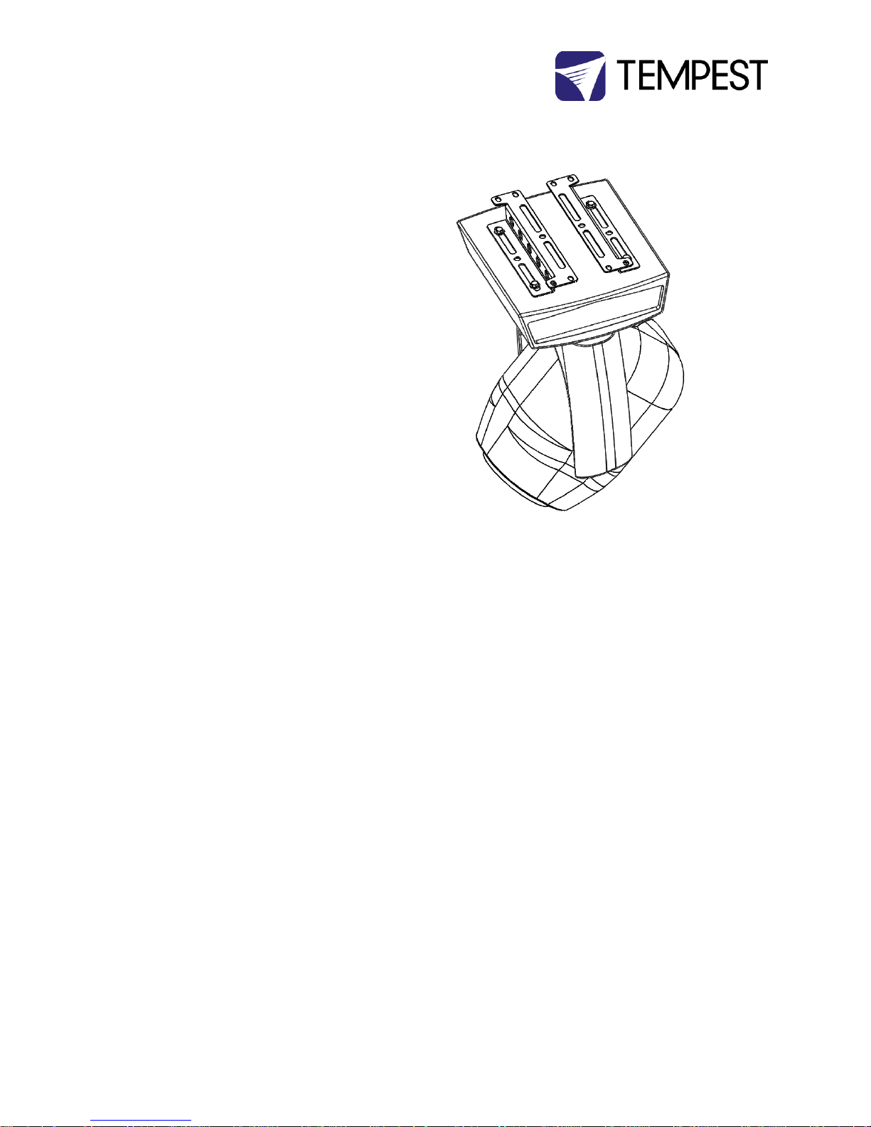
Screws
Many luminaire bases incorporate threaded holes for
mounting screws.
1. Simply screw into the luminaire base using the
appropriate screws (not supplied).
2. Check that the luminaire is centered and that the
ends of the mounting bars are parallel.
3. This is the most robust mounting method.
Tip: In some cases, you may find suitable threaded holes by
removing the rubber feet from the luminaire base.
Page 38
Tornado G4 User Manual 38
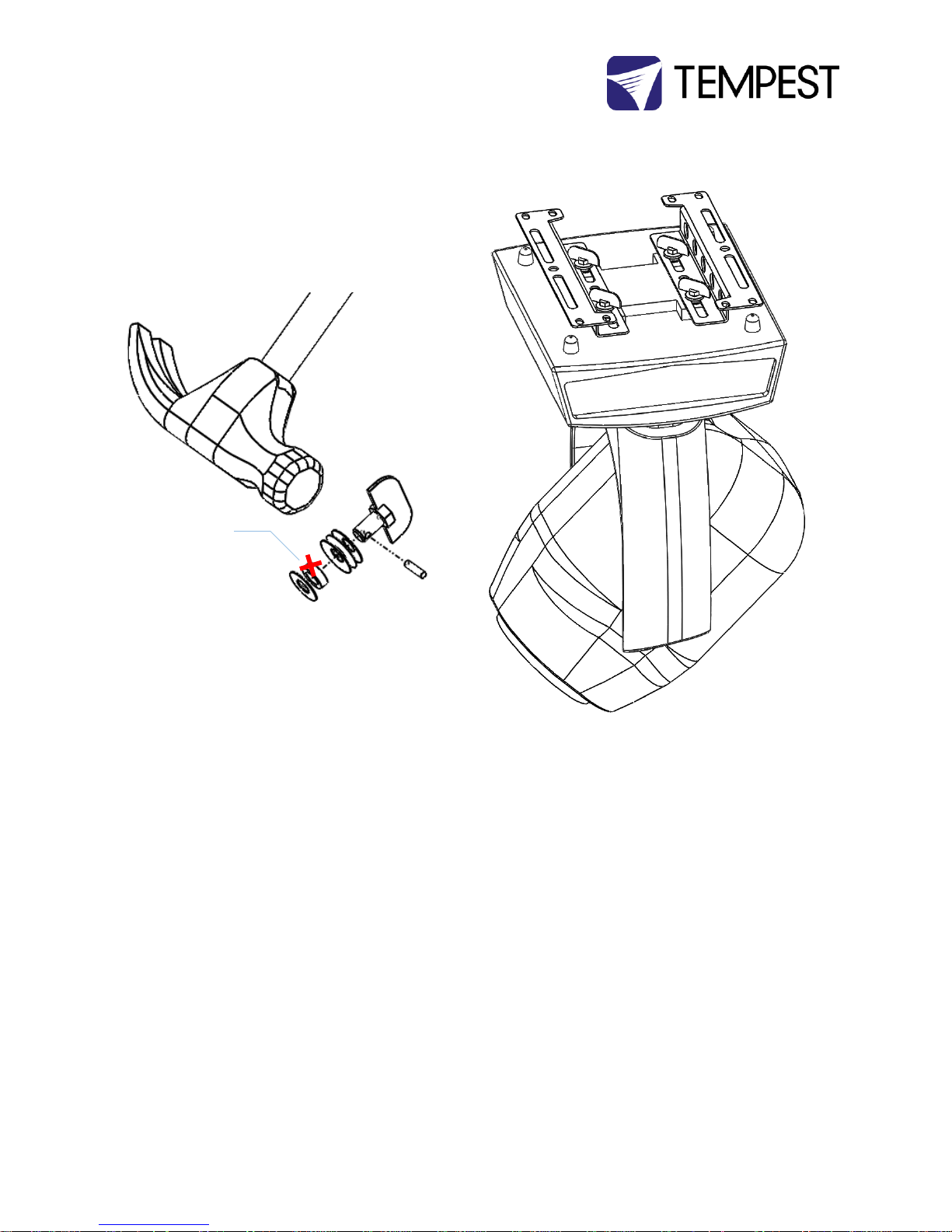
Quarter-Turn Fasteners (QTF)
Many luminaires with omega clamps do NOT have
threaded mounting holes. In this case:
1. Use a hammer to knock out the steel pin from the
omega clamp quarter-turn fasteners.
2. Remove the QTF from the omega clamp.
3. If there is a spacer on the QTF, remove and discard it
4. Re-assemble the QTF and replace the pin (tap home
with a hammer)
5. Use the QTFs to fasten the mounting bars to the
luminaire base.
TIP: If the QTFs are not tight, take them apart and add a
flat washer to pack out the length.
Discard spacers like this
Page 39
Tornado G4 User Manual 39
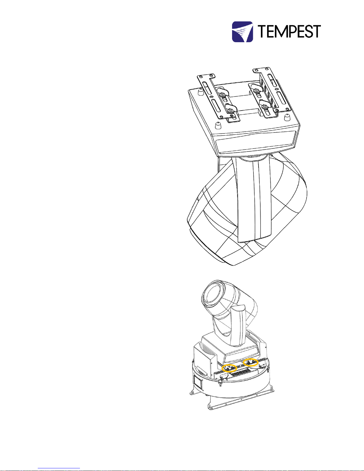
6. Re-assemble the QTF. NOTE: Some QTFs may have
spacers that are too wide (>12.7mm/.5in) to fit the
Tornado mounting slots. Discard these spacers.
7. Use the QTFs to secure the mounting bars to the
luminaire base.
Check that the luminaire is centered and that the ends of
the mounting bars are parallel.
Install Luminaire in the Tornado Base
Now take the luminaire, with mounting bars, and install
into the Tornado enclosure base, using the 8mm carriage
bolts, washers and nuts you removed at the start of this
process.
Page 40
Tornado G4 User Manual 40
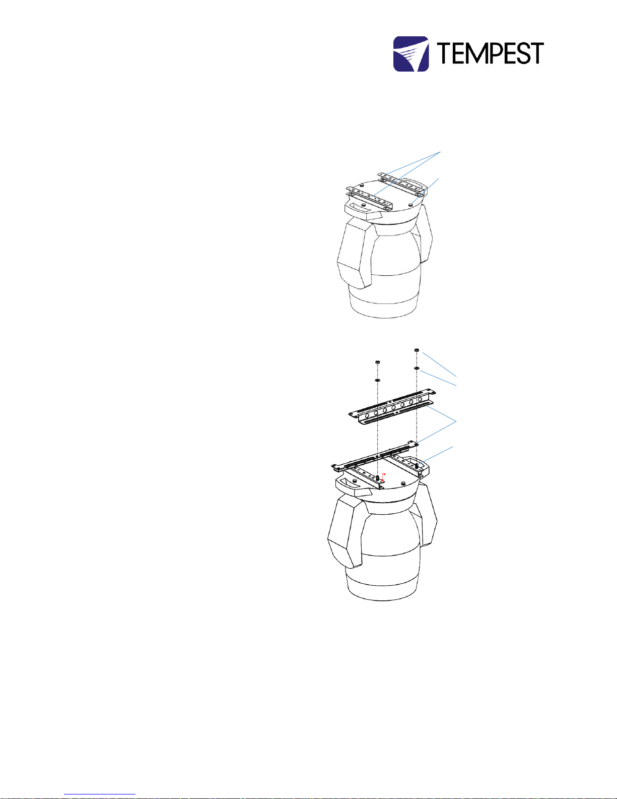
Vari-Lite Truss Adapters
Vari-Lite luminaires come with a pair of proprietary truss
adapter brackets that snap onto ‘buttons’ on the base of
the luminaire.
1. Snap the adapter brackets onto the luminaire
buttons, following the manufacturer’s
instructions
2. Bolt the luminaire mounting bars to the truss
adapter brackets, using the M12 mounting
hardware supplied
3. Replace the whole assembly in the Tornado
base and secure with the 8mm carriage bolts
supplied.
Vari-Lite Truss Adapter
Brackets
Buttons
M12 Nut
M12 Washer
Luminaire Mounting
Bars
M12 x 25 Bolt
Page 41
Tornado G4 User Manual 41
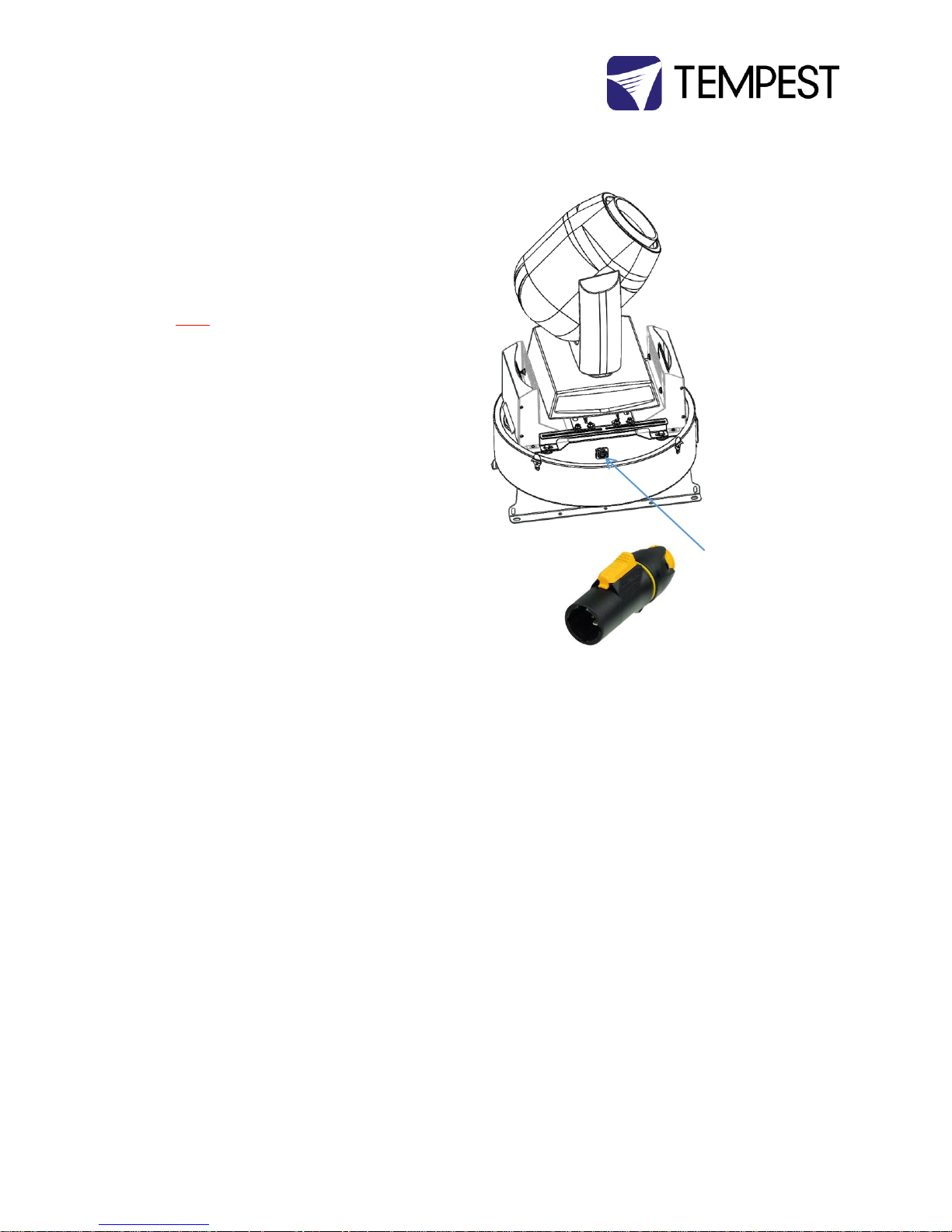
Connect Luminaire Power
1. Connect the luminaire power cable into the
PowerCon True outlet provided
2. Connect luminaire control wiring, following
manufacturer’s instructions
3. Connect all cables and test luminaire
IMPORTANT:
YOU MUST CONNECT THE LUMINAIRE TO THE
LUMINAIRE OUTLET. IF THE LUMINAIRE FEED
BYPASSES THE DEC CONTROLLER, THE VENTILATION
SYSTEM WILL NOT WORK AND THE LUMINAIRE WILL
OVERHEAT.
Neutrik PowerCon True
Outlet.
Use Neutrik PowerCon
True plug, item #
NAC3MX-W
Page 42
Tornado G4 User Manual 42
Routine Maintenance
Check the following every six months:
Clean Acrylic Globe
Clean Tornado globe using an acrylic cleaner/polish,
window cleaning fluid or detergent. Use a soft, lint free
cloth.
Check Filter
In most cases the filter will be good for 1-2 years. If the
filter becomes clogged the temperature inside the
enclosure will start to rise. This is an indication that the
filter must be changed.
Filter Part Numbers:
20.24.23 Tornado 1850-1975 Electrostatic Filter
20.24.23.HF Tornado Marine 1850-1975 Salt Fog Filter
20.24.32 Tornado 2000-2300 Electrostatic Filter
20.24.32.HF Tornado Marine 2000-2300 Salt Fog Filter
20.24.38 Tornado 2400-2500 Electrostatic Filter
20.24.38.HF Tornado Marine 2400-2500 Salt Fog Filter
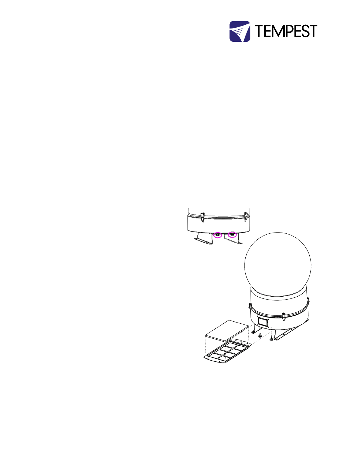
To replace the filter
1. Loosen the filter knobs on the back of the
enclosure
2. Remove the filter knobs on the front of the
enclosure (DEC User Interface side)
3. Slide out the filter Tray
4. Replace the filter (electrostatic foam filters may
be washed with water and a mild detergent)
5. Replace the filter tray
6. Tighten all filter knobs
Loosen back filter
knobs
Remove front filter
knobs
Slide filter
clamp
towards you
Lift out filter for
cleaning or
Page 43

Tornado G4 User Manual 43
Check Temperature/Humidity Sensor
If the sensor above the DEC4 cover is defective, the
controller may not operate correctly. A defective sensor
will result in one of three messages appearing on the DEC
user interface.
If you see any of these messages, contact Tempest for a
replacement sensor.
RH: 5%
RH: 100%
RH: ####
For After Sales Support
Contact your Tempest dealer or email [email protected]
Page 44

Tornado G4 User Manual 44
Troubleshooting
Luminaire does not have power:
1. Check Luminaire power switch
2. Check luminaire is plugged into DEC4 luminaire
outlet
3. Check that enclosure feed circuit is on
4. Check DEC4 User Interface leds are on. If feed
circuit is on and UI leds are off, check feed wiring
to DEC terminals and meter DEC4 luminaire
outlet for power
5. If UI lamp led is on and DEC4 luminaire outlet is
live, there is a luminaire fault.
Enclosure overheats:
1. Is the luminaire connected to the DEC4 luminaire
receptacle? If the luminaire is powered
independently the controller has no way to know
when to turn on the exhaust fans!
2. Is the filter clogged or obstructed?
3. Check that the Fan led on the UI is on when the
luminaire is running. If not, then the luminaire is
probably not connected to the DEC (see 1).
4. If the fan led is on, check that the fan is running. If
not, check fan wiring. If wiring is ok, fan may be
faulty.
5. Check the UI display for RH (relative humidity)
message. If display reads RH 5%, RH 100%, or
RH###, there is a sensor fault. Contact Tempest
for a replacement sensor.
Dirt/Debris inside enclosure
1. Filter is either missing or damaged?
2. Filter is not properly seated
3. Side panels or back door is not firmly latched
Water in enclosure
1. Check the drain holes in the bottom of the
enclosure. If they become blocked, and water
that gets in cannot escape.
2. Check seals around the globe and globe collar
Fan LED is on but fans do not operate
The exhaust fan is protected by a 20mm 4A slow-blow
fuse on the DEC4 motherboard, and a secondary fuse
on the fan board. In very exceptional cases it is
possible that either fuse could fail. Check visually.
The fuse is protected with a clear resin sealant and
soldered to the circuit board. With care, you can desolder the fuse and replace it, but we recommend
replacing the DEC4 motherboard to maintain the
integrity of the board’s conformal coating.
Heater LED is on but heater does not operate
The heater is protected by a 20mm 10A slow-blow
fuse on the DEC4 motherboard. In very exceptional
cases it is possible that it could fail. Check visually.
The fuse is protected with a clear resin sealant and
soldered to the circuit board. With care, you can desolder the fuse and replace it, but we recommend
Page 45

Tornado G4 User Manual 45
replacing the DEC4 motherboard to maintain the
integrity of the board’s conformal coating.
None of the above?
Contact [email protected]
Page 46

Tornado G4 User Manual 46
Warranty
INSPECTION/WARRANTY/RETURNS.
A. Customer, at its sole expense, shall inspect all Goods promptly upon receipt and accept all Goods that conform to the
specifications or catalog. All claims for any alleged defect in or failure of the Goods or Seller's performance to conform to the
Contract, capable of discovery upon reasonable inspection, must be set forth in a written rejection notice detailing the alleged
non-conformity, and be received by Seller within thirty (30) calendar days of Customer's receipt of the Goods. Failure by
Customer to notify Seller of the alleged non-conformity within thirty (30) days will be conclusive proof that the Goods have
been received by Customer without defects or damage, and in the quantities specified on the bill of lading and shall constitute
an irrevocable acceptance of the Goods and a waiver of any such claim in connection with the Goods.
B. Seller warrants to Customer only that the Goods will be free from defects in material and workmanship at the time of
delivery and, subject to the exceptions and conditions set forth below, for the following period (the "Warranty Period"):
twelve (12) months from the date of shipment by Seller. Seller may provide additional years of warranty coverage beyond 12
months, at the rate of 2.5% of the net sale price per year, up to a total of four additional years’ coverage beyond the standard
12 month warranty period. Seller will remedy a defect as set forth in paragraph 7 D, below, (the "Warranty"). The Warranty is
subject to each of the following exceptions and conditions:
1. Customer must promptly (and in all events within the Warranty Period) notify Seller of any alleged defect in a written notice
(the "Notice") which shall set forth the quantity, catalog number, finish, original purchase order number, Seller's invoice
number on which Goods were originally billed and a statement of the alleged defect, along with digital photographs showing
such defects where feasible.
2. The Warranty shall not apply: (i) to any claimed defect that was capable of discovery upon reasonable inspection and
deemed to be waived under paragraph A, above; (ii) to any Goods that have been subject to misuse, abnormal service or
handling, or altered or modified in design or construction; (iii) to any Goods repaired or serviced by any person other than
Seller's authorized service personnel or to Goods installed other than according to installation instructions, or (iv) with respect
to normal wear and tear.
3. Seller makes no Warranty with respect to parts or components that are not the product of Seller, and specifically makes no
warranty whatsoever for equipment housed inside enclosure products manufactured by Seller.
4. The Warranty is Seller's exclusive warranty with respect to the Goods. Seller makes no warranties, guarantees or
representations, express or implied, to Customer except as set forth in this section. ALL OTHER WARRANTIES, EXPRESS OR
IMPLIED, INCLUDING, WITHOUT LIMITATION ANY IMPLIED WARRANTY OF MERCHANTABILITY OR OF FITNESS FOR USE OR FOR
A PARTICULAR PURPOSE, ARE HEREBY EXCLUDED AND DISCLAIMED.
C. Seller will accept the return of Goods properly rejected under paragraph A, above, or as to which Notice of an alleged
breach of Warranty has been timely given and such Goods may be returned to Seller, freight prepaid, but only upon
Customer's receipt of Seller's written return material authorization ("RMA") and shipping instructions. The RMA shall be void if
the Goods are not received within 45 days after issuance of the RMA. No deduction or credit in respect of any rejected or
returned Goods shall be taken until Customer has received Seller's further written deduction or credit/authorization following
Seller's inspection to confirm nonconformity or defect. Seller will charge to Customer any and all costs incurred by Seller in
connection with the handling, shipping, inspection and disposition of any returned Goods that are determined by Seller not to
have been nonconforming upon Delivery or as to which the warranty hereunder is not applicable.
D. UPON ANY PROPER RETURN PURSUANT TO PARAGRAPH C, ABOVE, WHETHER IN CONNECTION WITH A REJECTION OF
GOODS OR AN ALLEGED BREACH OF WARRANTY AND BASED UPON THE CONDITIONS SET FORTH IN THIS PARAGRAPH 7,
SELLER AGREES THAT IT WILL, AS THE SOLE AND EXCLUSIVE REMEDY UNDER THE CONTRACT OR OTHERWISE, FOR ANY
NONCONFORMITY OR BREACH OF WARRANTY, AND AT SELLER'S SOLE ELECTION: (i) REPAIR SUCH GOODS; OR (ii) REPLACE
SUCH GOODS.
Page 47

Tornado G4 User Manual 47
Appendix – TEMP Protocol
AVAILABLE TO SPECIAL ORDER
Tempest can optionally provide a firmware load that facilitates TEMP over RS485, suitable for interfacing to an Ethernet
adapter. TEMP is a lightweight proprietary ASCII based protocol, intended for rapid integration into management systems.
With TEMP and a suitable RS485 to Ethernet adaptor connected to the DEC DMX connectors, your DEC may be configured and
monitored over an IP network.
Please contact factory for ordering information.
Physical Layer
1. EITHER: Use a 51.EN Ethernet daughter board plugged directly to the DEC4 motherboard, connected to your TCP/IP
network.
2. OR: Use a 51.485 RS485 daughter board on each of a number of DEC4 motherboards, and use one of the convertors
listed below to bridge to your TCP/IP network.
Suitable Converters include:
http://gridconnect.com/rs485-ethernet.html
http://www.audon.co.uk/lan232/ENET485-POE.html
http://uk.rs-online.com/web/generalDisplay.html?id=brainboxes
Developer’s Guide
Download the Developer Guide from www.tempest.biz/tech-support.
 Loading...