

Page 1
User Manual and Installation Guide
Tornado Moving Light Enclosures
Tempest Lighting, Inc.
13110 Saticoy Street, Unit C
N. Hollywood, CA 91605, USA
Tel +1 818 787 8984
Fax +1 818 982 5510
www.tempest.org
For the following products, manufactured after
August 2013
Tornado 1900, 1950
Tornado 2000, 2100
Tornado 2200, 2300
Tornado 2400
With DEC3.3 GoldilocksTM rev 0.01.006 or higher
In the interest of continuous product improvement, the information in this document is subject to change without
notice. Neither Tempest Lighting, Inc. nor its representatives or agents may be held liable for expense or injury
arising from it.
© Tempest Lighting Inc. All Rights Reserved September, 2013
Lamp
Heater Fan RelayOn DMXTemp
ESC OK
User Manual
Tornado Moving Light
Enclosures
Cyclone Enclosure User Manual page 1
Page 2

Table of Contents
1 Introduction .........................................................................................................6
Dimensions ...................................................................................................7
2 Installation ........................................................................................................ 10
Planning...................................................................................................... 11
Mounting – Tornado 1900-1950 ............................................................... 11
Mounting – Tornado 2000 and up ............................................................ 12
Orientation Guidelines ............................................................................... 14
Drainage ..................................................................................................... 15
Installation above public Spaces ............................................................... 16
3 Wiring and Control ........................................................................................... 17
Conduit entry holes ................................................................................... 17
One or Two Power Circuits? ...................................................................... 18
4 Digital Enclosure Control DEC3.3
TM
with GoldilocksTM .......................... 20
DEC3.3 Schematic ...................................................................................... 21
DEC3.3 Main Functions.............................................................................. 22
Factory Settings – Basic Mode ................................................................... 22
Operating Modes ....................................................................................... 23
DEC3.3 Control Parameters ....................................................................... 24
Start-up Validation ..................................................................................... 25
DMX Connections....................................................................................... 25
Remote Device Management (RDM) .......................................................... 27
Control Interface ........................................................................................ 28
RDM Monitoring and Configuration .......................................................... 32
Firmware Upgrade over RDM..................................................................... 33
5 Mounting the Luminaire ................................................................................... 34
Tornado 1900-1950 .................................................................................. 35
Tornado 2000, 2100, 2200, 2300 ............................................................ 36
Vari*Lites and the Vari*Lite Hook Bracket ................................................ 38
Martin MAC III and other tall Luminaires .................................................. 39
Shorter Luminaires Requiring Bracket Standoffs ...................................... 40
Cyclone Enclosure User Manual page 2
Page 3

Mounting the Luminaire – Tornado 2400 ................................................. 41
6 Closing up the Enclosure ................................................................................. 42
7 Operation .......................................................................................................... 44
8 Routine Maintenance ........................................................................................ 45
9 Troubleshooting ............................................................................................... 47
10 Limited Warranty .............................................................................................. 49
11 Tempest Product Support ................................................................................ 50
Cyclone Enclosure User Manual page 3
Page 4

CERTIFICATE AND DECLARATION OF CONFORMITY FOR CE MARKING
Tempest Lighting, Inc.
13110 Saticoy Street, Unit C, North Hollywood, CA 91605, USA
t: +1 818 787 8984 f: +1 818 982 5770 e: [email protected]
www.tempest.org
Tempest Lighting, Inc. declares that their:
Tornado Lighting Enclosure Series 19xx.xxx, 2xxx.xxx
complies with the Essential Requirements of the following EU Directives:
Low Voltage Directive 2006/95/EC Test Report 60065-2000-13
Electromagnetic Compatibility Directive 2004/108/EC Test Report 61000-2000-15
and further conforms with the following EU Harmonized Standards:
EN 60065 : 2002 Test Report 60065-2000-13
EN 60529:2001-2002 Test Report 60529-2000-14
EN 61000-6-3:2007+A1:2011 Test Report 61000-2000-15
EN61000-6-1:2007 Test Report 61000-2000-15
EN55015:2006+A2:2009 Test Report 61000-2000-15
Dated: 1
st
March 2013
Position of signatory: President
Name of Signatory: Tim Burnham
Signed below:
on behalf of Tempest Lighting, Inc.
. . . . . . . . . . . . . . . . . . . . . . . . . . . . .
Cyclone Enclosure User Manual page 4
Page 5

This is to certify that the following products
Tornado 2000.US(H,V) Lighting Enclosure
Tornado 2050.US Lighting Enclosure
Tornado 2000.US(H,V) Lighting Enclosure
Tornado 2200.US(H,V) Lighting Enclosure
Tornado 2300.US(H,V) Lighting Enclosure
Tornado 2400.US Lighting Enclosure
Have been tested and approved to standards UL 508 (electrical) and UL 50 (environmental), as
NEMA 3R enclosures, for use in the United States and Canada.
This declaration is made by the manufacturer
Tempest Lighting, Inc.
13110 Saticoy Street, Unit C
North Hollywood, CA 91605, USA
This declaration is based on tests that were conducted on the submitted samples of the above
mentioned products.
Listing Report No. 3198609LAX-001a refers.
Dated: December 12th, 2010
Signature . . . . . . . . . . . . . .
Tempest Lighting Inc
Tempest Lighting, Inc.,
13110 Saticoy Street, North Hollywood, CA 91605, USA
www.tempest.org [email protected]
t: +1 818 787 8984
f: +1 818 982 5582
Cyclone Enclosure User Manual page 5
Page 6

1 Introduction
Using This Manual
Please read this manual in its entirety before starting work. All the information contained is
important, and should be read carefully before proceeding. Heed all warnings and advisories.
Terminology:
Enclosure - Tornado Lighting Enclosure
Luminaire - intelligent lighting fixture that will be placed into the enclosure
DMX - ANSI E1.11-2008, Entertainment Technology - USITT DMX512-A, Asynchronous Serial Digital
Data Transmission Standard for Controlling Lighting Equipment and Accessories.
RDM - ANSI E1.20-2006, Entertainment Technology - RDM, Remote Device Management over
DMX512 Networks
Icon Key:
Valuable information
Electrical Warning
Safety Information
IMPORTANT SAFETY NOTICE: All safety instructions provided by the luminaire manufacturer must be
followed carefully. Failure to do this may void both the luminaire and the enclosure warranties.
When working at heights or in awkward locations, it is imperative to develop a safety plan, based on
the information in this manual, and on local conditions and safety regulations. The safety plan must
be approved by the site engineer/safety officer, as appropriate to local conditions. NEVER attempt
to install Tornado enclosures in high winds or when precipitation is present or imminent.
Cyclone Enclosure User Manual page 6
Page 7
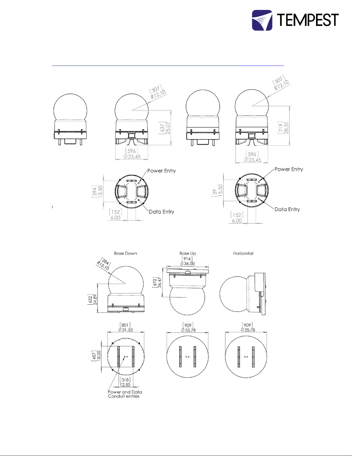
Dimensions
CAD drawings in DWG and PDF format are available for download at www.tempest.org
Tornado 1900 Tornado 1950
Down)
Tornado 2000-2100
Tornado 2000-2100
Cyclone Enclosure User Manual page 7
Page 8
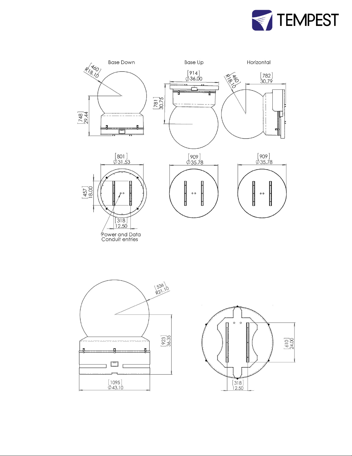
Tornado 2200-2300
Tornado 2400
Cyclone Enclosure User Manual page 8
Page 9
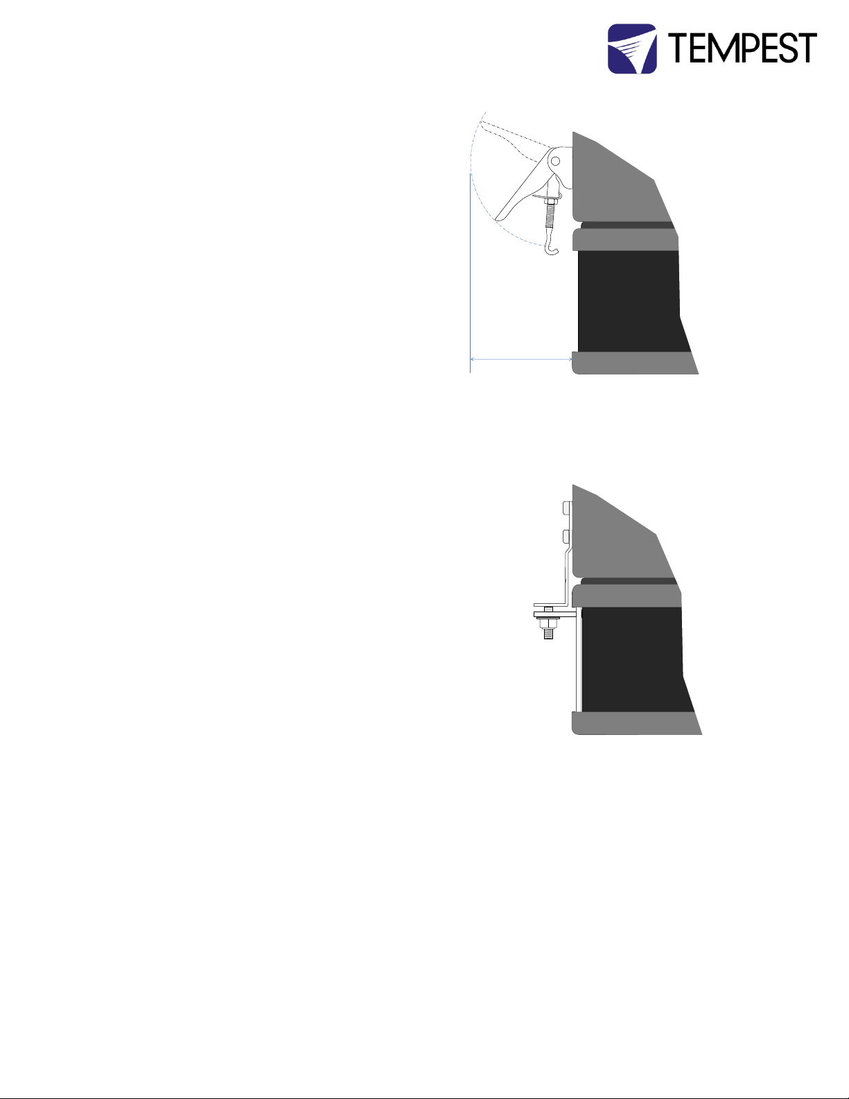
Note – Draw Latch Clearance
Allow adequate clearance for all latches.
Note - Marine Latches
Marine Latches require a tool to open the enclosure.
Latch Plate
3”/75mm
Latch Plate
Marine Latch.
Designs vary slightly by
model.
Note: Tornado 2400 may be installed base up or base down only
Cyclone Enclosure User Manual page 9
Page 10

2 Installation
Safety and Warnings
Read the Manual before installing the enclosure
Read the manual before opening or servicing the enclosure
Never leave the enclosure unattended when open.
Ensure all bolts and terminals are tight and clean
Do not touch the heater unless you can be sure that it is cool.
Observe all warning labels in the enclosure itself.
Do not open any electrical boxes until power is off
Do not open the enclosure in wet weather.
Never move the enclosure with the luminaire inside.
Never handle the enclosure by the globe.
Always lift the enclosure from under the base.
Cyclone Enclosure User Manual page 10
Page 11
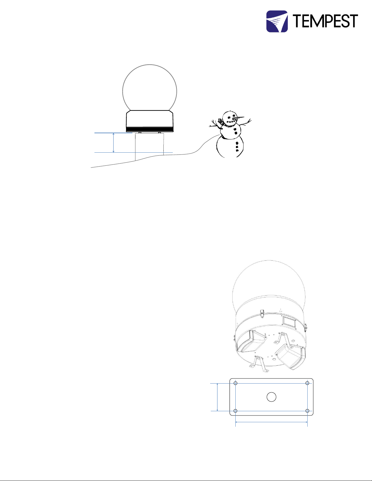
Planning
Snow clearance:
Enclosure must be powered 24/7/365.
Warning: This installation cannot be safely completed by 1 person.
Mounting – Tornado 1900-1950
Each Enclosure must be wall, floor or ceiling mounted with the two stainless steel
brackets provided.
Tempest Lighting recommends only stainless steel
mounting hardware for permanent installation
outdoors.
Floor, Wall or Ceiling Mounting
Use the two stainless steel mounting brackets provided
with the Tornado 1900/1950.
Fix the holes in the bracket feet to a secure structure using
3/8” [M10] stainless steel hardware (not supplied).
Pole Mounting
To mount to the top of a pole, fabricate a plate
with four 0.434”/11mm holes and weld to the top
of your pole. Use these dimensions:
MINIMUM
24”/60c
6”
[152mm]
Wiring Hole
15.5”
[394mm]
Cyclone Enclosure User Manual page 11
Page 12
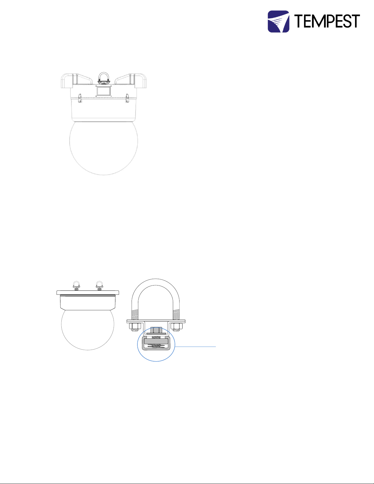
Pipe Mounting
Pipe Clamps
4900.MCT Pipe clamp, for pipes 1.5” (38mm) to 2” (50mm) OD.
Order TWO per enclosure.
4925.MCT Pipe clamp, for pipes 2” (50mm) to 2.5”/64mm OD.
Order TWO per enclosure.
Pipe Clamps mount to the enclosure base in the same
locations as the mounting brackets provided.
NOTE: Chesboro’ style half-couplers may be used for
temporary installations, but are not recommended for
permanent installs.
Mounting – Tornado 2000 and up
Each Enclosure must be mounted with FOUR points.
Tempest Lighting recommends only stainless steel mounting hardware.
The bolts attaching the enclosure to its shipping pallet are mounting bolts. Do not Discard.
All mountings must be made using the two Unistrut channels on the base of the enclosure.
Pipe Mounting
Pipe Clamps
4900.MCT Pipe clamp, for pipes 1.5” (38mm)
to 2” (50mm) OD. Order FOUR per enclosure.
4925.MCT Pipe clamp, for pipes 2” (50mm) to
2.5”/64mm OD. Order FOUR per enclosure.
Note: These parts are supplied with the
Tornado enclosure.
Cyclone Enclosure User Manual page 12
Page 13
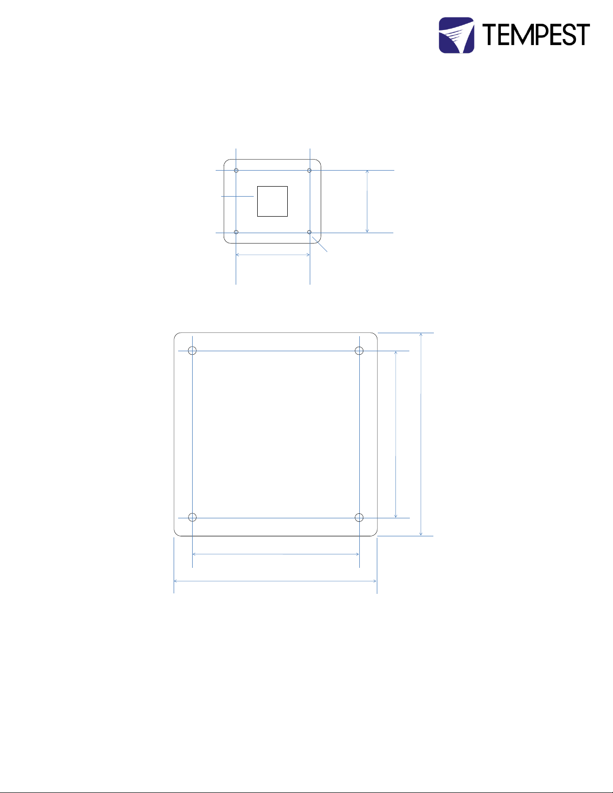
Mounting plate Guidelines
Use ¼” (6mm) or greater galvanized steel or stainless steel plate.
Do not obstruct wiring access.
Tornado 2000, 2200, 2300 Mounting Hole Pattern
Tornado 2400 Mounting Hole Pattern
10.0”
254mm
12.5”
317.5mm
Mounting holes
9/16”/13mm
Wiring Access
opening, 5” x 5”
(125 x 125mm)
12.25” /311mm
12.25” /311mm
15.00” /381mm
15.00” /381mm
Cyclone Enclosure User Manual page 13
Page 14
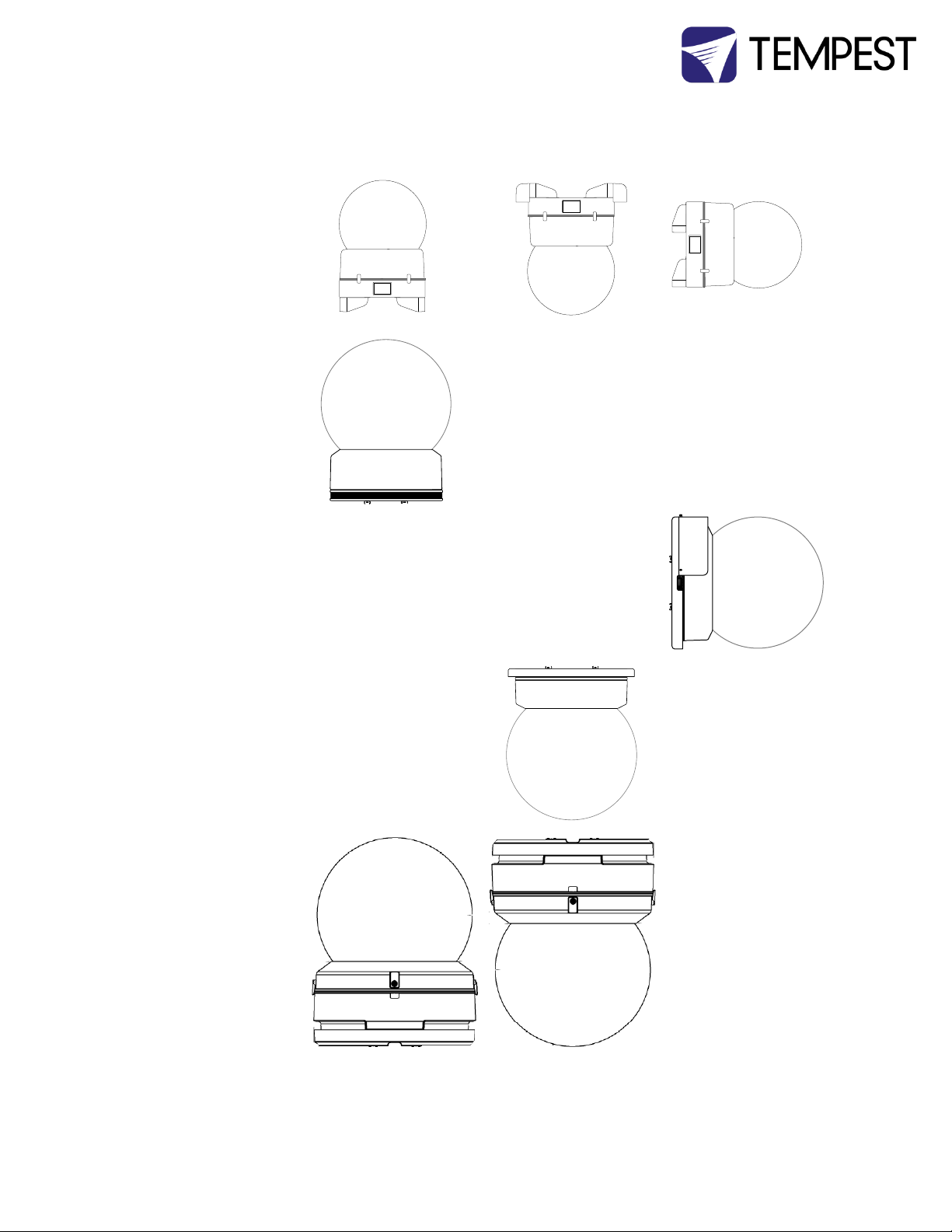
Orientation Guidelines
Tornado 1900.xx
Tornado 1950.xx
Tornado 2000.xx
Tornado 2100.xx
Tornado 2200.xx
Tornado 2300.xx
Tornado 2000.xxH
Tornado 2100.xxH
Tornado 2200.xxH
Tornado 2300.xxH
Tornado 2000.xxV
Tornado 2100.xxV
Tornado 2200.xxV
Tornado 2300.xxV
Tornado 2400.xx
42”
(1067mm)
35.25”
(895mm)
42”
(1067mm)
35.25”
(895mm)
34.25”
(870mm)
56.25”
(1429mm)
43.1”
(1092mm)
34.25”
(870mm)
56.25”
(1429mm)
43.1”
(1092mm)
Cyclone Enclosure User Manual page 14
Page 15
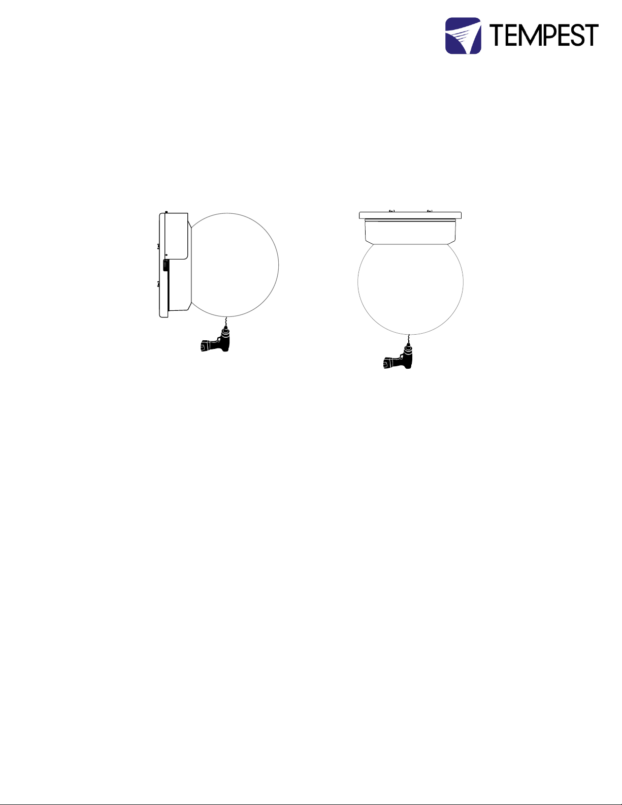
Drainage
For base up/globe down or horizontal operation, a small drainage hole will be drilled in the globe,
to permit any water draining through the enclosure to exit harmlessly.
This will normally be done at the factory, but if done on site, YOU MUST USE THE APPROPRIATE
TAPERED DRILL BIT, OBTAINABLE FREE OF CHARGE FROM TEMPEST LIGHTING. A standard drill
bit may crack the plexiglass globe. Tempest Lighting will not be responsible for such damage.
Horizontal Enclosures – be sure to replace the globe with the drainage hole at the lowest point
after relamping.
Note: A tapered drill bit is included with all Tornado 1900-1950 shipments. Weep holes must be
drilled on site as part of the installation process.
Cyclone Enclosure User Manual page 15
Page 16
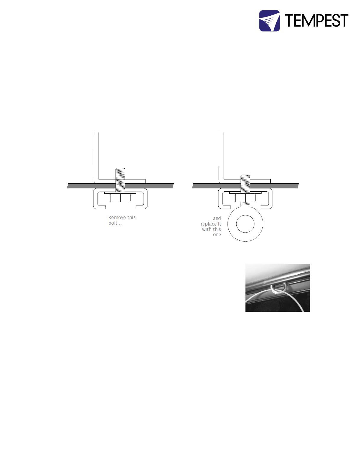
Installation above public Spaces
If the Tornado enclosure is to be installed above an area accessible to the public (eg a street or an
auditorium), some jurisdictions require a safety bond to be installed.
A stainless steel eyebolt is included with base-up and horizontal versions, and should be installed
as follows:
1. Remove one of the four bolts holding the Unistrut onto the enclosure base
2. Replace it with the eye bolt, washer and nut supplied, and screw down tight
Safety Bond
Use a suitably-rated steel wire rope, threaded through the eyebolt, and
attach securely to a structural member, in accordance with local safety
regulations.
Cyclone Enclosure User Manual page 16
Page 17
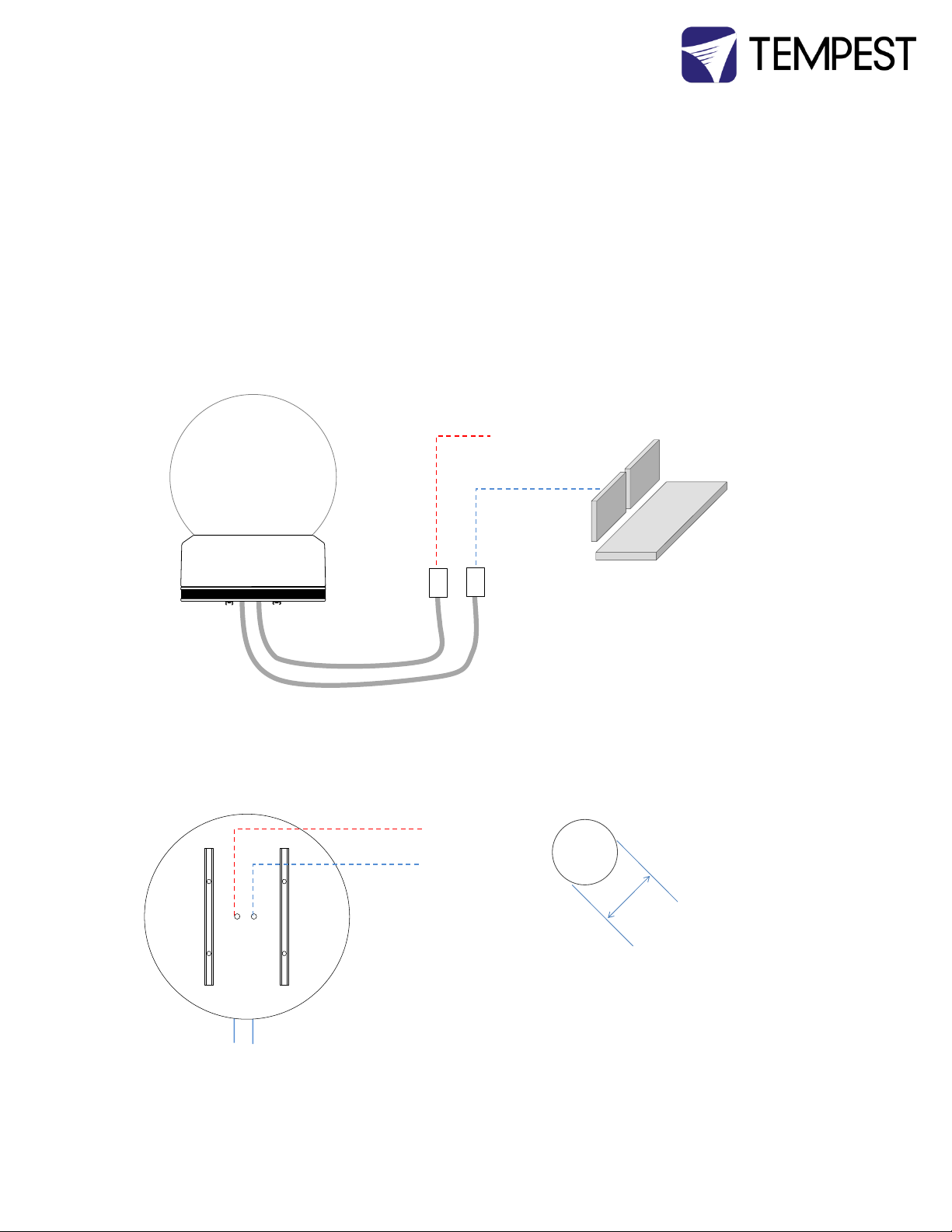
3 Wiring and Control
All electrical work must be carried out by a properly licensed electrician, in compliance with
local electrical standards. Failure to observe this point will void the factory warranty for the Tempest
Enclosure.
1 Switch off power to the branch circuit, carefully following lockout and tag-out procedures. Failure to do so
could cause serious injury or death.
2 You will need two electrical junction boxes, located within a short distance from the enclosure, one for power,
one for DMX control. Use outdoor-rated flexible conduit between the box and the enclosure.
3 AC and control circuits must be wired in separate conduits.
Conduit entry holes
Power and DMX conduit entries
The conduit entry holes accept US ½” conduit fittings, and
international 20-22mm (OD) conduit fittings.
For temporary installations, use a suitable cable and clamp in the
same openings.
AC
Power
DMX
Control
Flexible Conduit
120VAC, or
208VAC
or 230VAC
Lighting
Control
AC Power
DMX Control
Ø 0.875”
22.2mm
Cyclone Enclosure User Manual page 17
Page 18
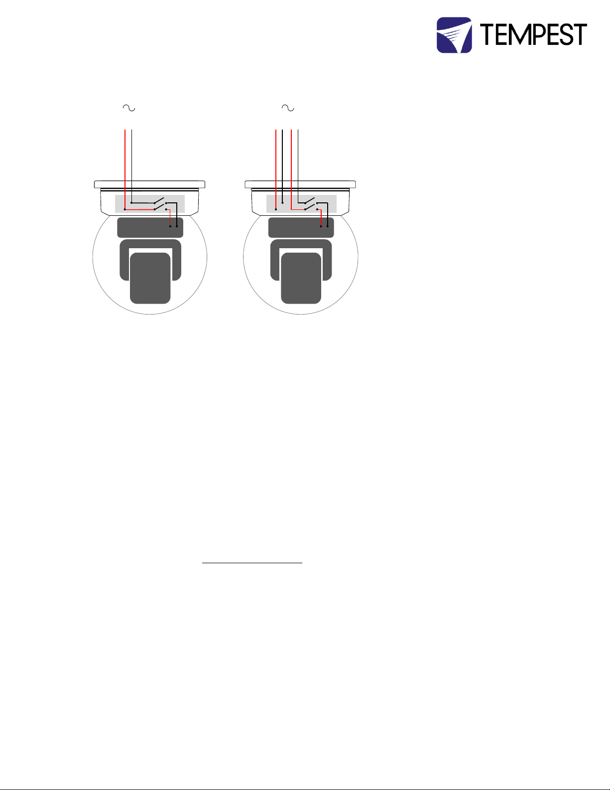
One or Two Power Circuits?
Single Feed Split Feed
Tempest enclosures may be wired on single or double line supplies. On a single feed, both
enclosure and luminaire are permanently on. With a double-line supply, you can switch off the
luminaire when not in use, while the enclosure continues to protect it 24/7.
Single Feed
Enclosure and luminaire are permanently on.
Enclosure and Luminaire must be rated for the same voltage.
Supply must be rated for luminaire current plus 150 watts.
Supply must be permanently ON.
Split feed
Enclosure power must be permanently ON.
Luminaire power may be switched off.
Enclosure power must be rated for 1150 watts.
Luminaire power must be rated for the luminaire (see luminaire manual).
Luminaire and enclosure power must be same voltage.
Either way, the enclosure must be powered 24/7, in order to protect the luminaire inside against
condensation and extremes of temperature.
Since the enclosure heater(s) never operate when the projector/fixture lamp is on, it is NOT
necessary to rate the power service for the SUM of the enclosure and the projector/light fixture.
1 21
IMPORTANT Tempest enclosures are supplied for either 120VAC 50/60Hz, or 208-240VAC,
ALL ELECTRICAL CONNECTIONS MUST BE UNDERTAKEN BY A QUALIFIED
Cyclone Enclosure User Manual page 18
50/60Hz operation. Tempest Lighting is not liable for damage or failure to
operate correctly due to connection to an inappropriate electrical supply.
ELECTRICIAN, IN COMPLIANCE WITH LOCAL NORMS AND STANDARDS.
Page 19
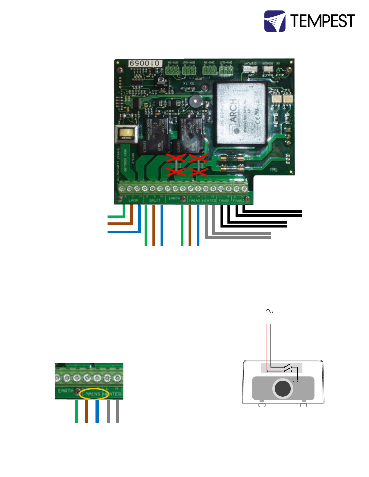
Projector Supply
(split mode)
Enclosure Supply
(100-250VAC 50/60Hz)
Fan 1
Fan 2
Heater(s)
Projector
receptacle
Cut here for split
supply operation
Fan 1
1
Split Feed Connections
Note: wire colors may differ depending on applicable electrical standards. European wire colors are shown here.
IMPORTANT: MAKE SURE THAT TERMINAL SCREWS ARE FULLY BACKED OUT BEFORE INSERTING WIRES.
Common Feed Connection (factory default)
Enclosure and projector share the same electrical circuit.
Circuit must be powered ON 24/7.
Connect incoming power to the terminals labeled MAINS:
(E) Earth/Ground
(L) Live
(N) Neutral
E L N
Cyclone Enclosure User Manual page 19
Page 20
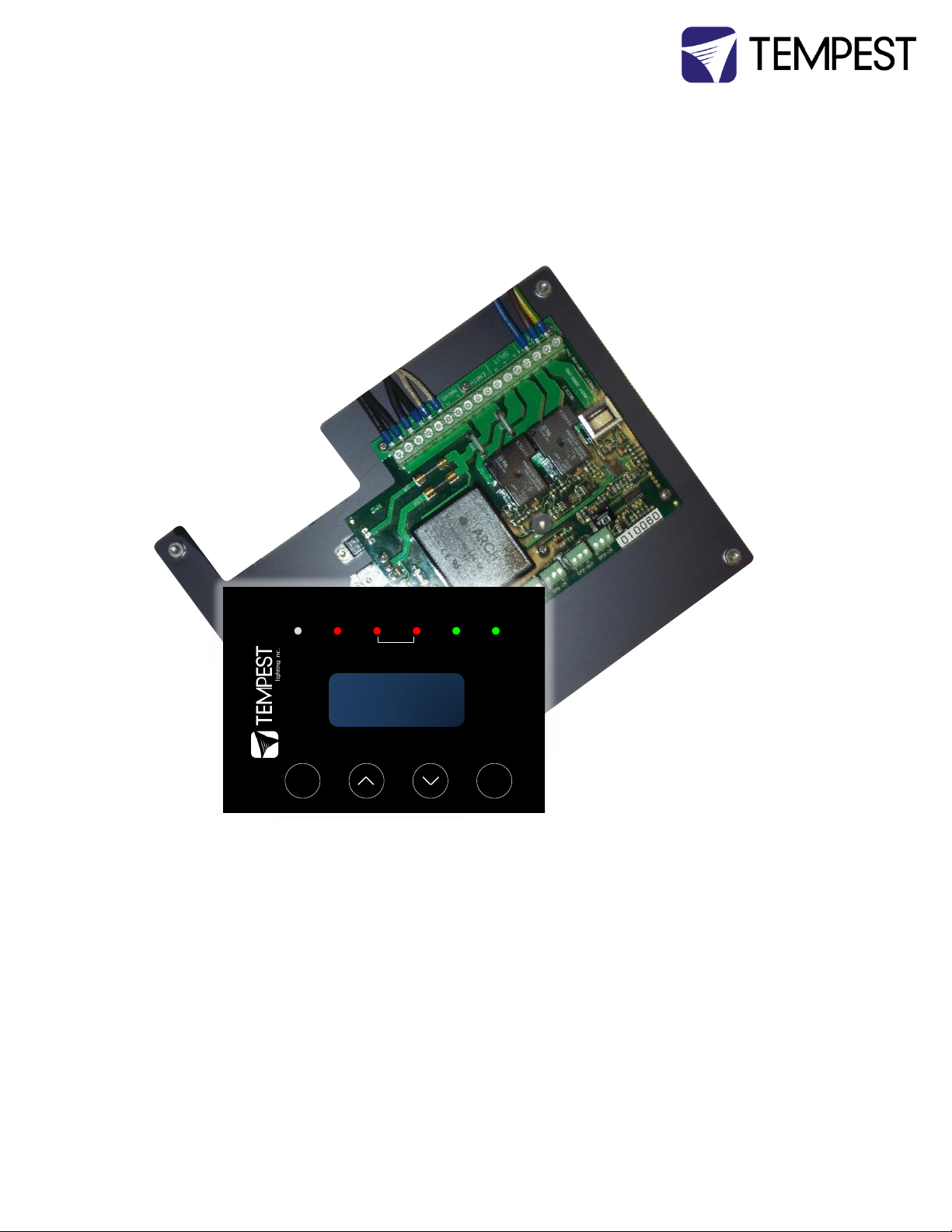
Lamp
Heater Fan RelayOn DMXTemp
ESC OK
4 Digital Enclosure Control
DEC3.3
TM
with Goldilocks
TM
DEC3.3TM – that’s Digital Enclosure Control, third Generation, revision 3 – is the brain of your
Tempest enclosure. It will maintain the internal environment in a comfortable temperature and
humidity range, and prevent condensation – the real killer of outdoor equipment. DEC3.3
monitors internal temperature, humidity and lamp current at all times, and uses this information
to control the enclosure’s lamp relay, fan(s) and heater(s). It can report back over the DMX cable,
using the RDM protocol (Remote Device Management) if desired.
From summer 2013 DEC is running Tempest’s new GoldilocksTM operating system (patents
pending). A completely new OS, Goldilocks analyzes temperature and humidity trends, targeting
and maintaining safe ranges, and acting to prevent condensation before it happens. Goldilocks is
also much more energy-efficient than previous generations, so your equipment is always in the
Goldilocks zone, and you save money too.
Cyclone Enclosure User Manual page 20
Page 21
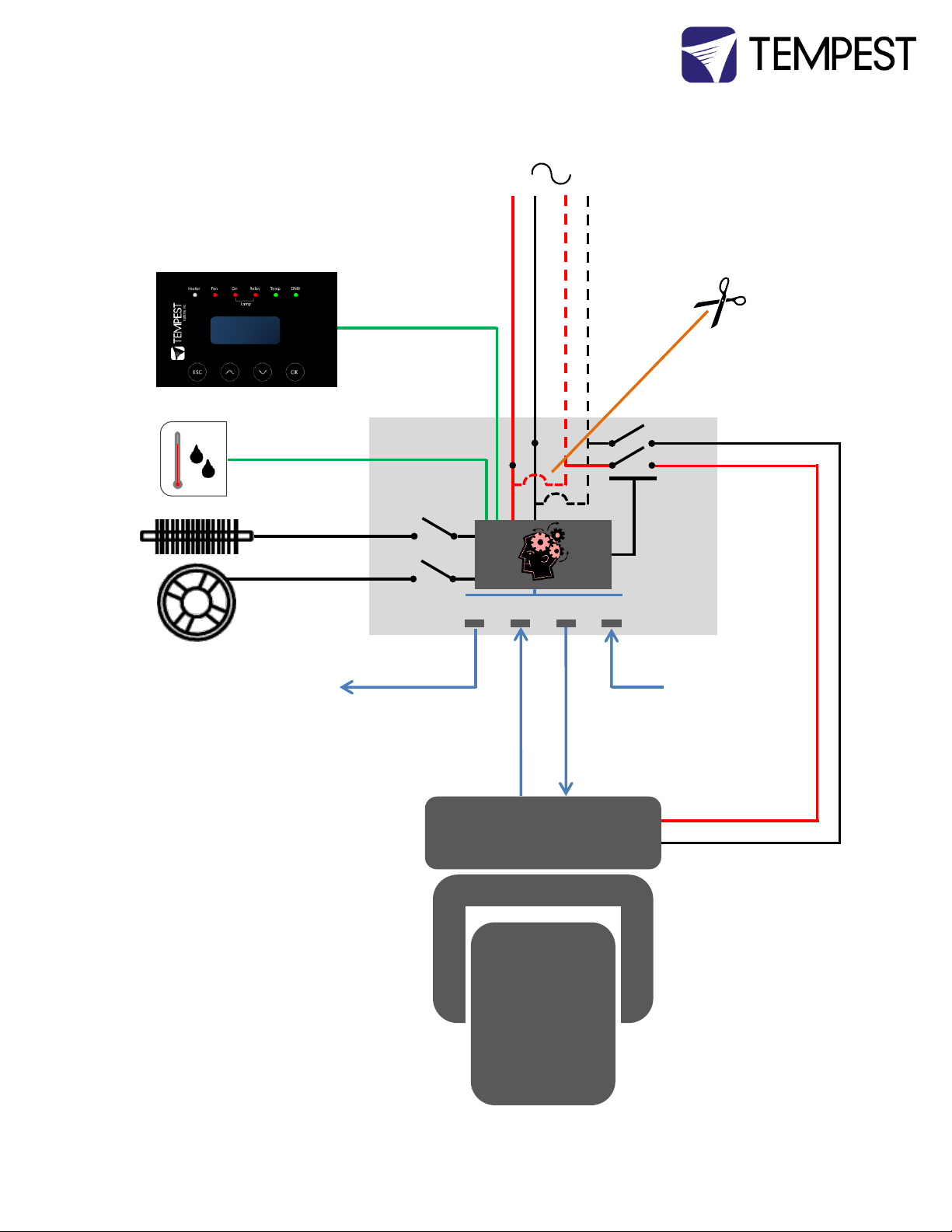
OUT OUTIN IN
DMX/RDM – RS485
AC FAN(S)
AC HEATER(S)
SENSOR
Cut links on
board for split
feed operation
MAIN AC Supply
Optional independent
SPLIT AC Luminaire Supply
DEC3.3 Schematic
Cyclone Enclosure User Manual page 21
Page 22

DEC3.3 Main Functions
1 Sense current to luminaire (lamp on/off)
2 Record lamp hours
3 Monitor temperature and humidity inside Enclosure
4 Maintain temperature at safe operating level
5 Maintain relative humidity within safe limits
6 Prevent condensation
7 Isolate luminaire in case of unsafe temperature
8 Report status over RDM
9 (Optional) remote luminaire relay control over DMX
DEC3.3 constantly monitors the following parameters:
Luminaire/Luminaire power
Line Voltage
Temperature
Humidity
DEC 3.3’s patented GoldilocksTM algorithm uses a combination of heaters and fans to maintain a
safe operating temperature and a safe relative humidity level that will not allow condensation to
take place.
As air is heated it is able to support more moisture without condensing, so Goldilocks uses heat
to raise the air temperature inside the enclosure in the event that relative humidity approaches
dewpoint.
Factory Settings – Basic Mode
In most applications, DEC3.3 will operate correctly with its factory default settings, in Basic
operating mode.
You do not need to do anything. Please skip to the Power Connections section below.
If your needs are more complex, read on.
Cyclone Enclosure User Manual page 22
Page 23

Operating Modes
DEC3.3 may operate in one of four modes, set using either the Front Panel or by RDM control. In
all configurations, the luminaire inside the enclosure may also be an RDM enabled device.
Basic Mode (factory setting)
Standard temperature settings
DMX and RDM disabled
Best for standalone operation
Monitor Mode
As Basic mode, plus:
RDM status reporting
RDM configuration – settings may be changed remotely or at the enclosure control
panel
DEC3.3 does not require a DMX signal to operate
Control Mode
As Basic mode, plus:
Enclosure functions as a 1-channel DMX device, with remote control of the lamp relay
Control mode is recommended for show control applications, but can be risky in live
show operation, since the DMX slot used for the enclosure MUST be kept high to
prevent the lamp relay from opening.
Service Mode
For trained service personnel only
Normal operation is suspended and the enclosure functions as a 3-channel DMX
device:
Service mode is ONLY for troubleshooting – DO NOT use Service mode for normal
operation.
o DMX level > 75% enables normal relay operation (normally ON)
o DMX level < 25% disables normal relay operation (relay turns OFF)
o This allows you to force a hard reset of the lamp relay in the event of a
luminaire malfunction
o Lamp Relay (Slot 1)
o Fans (Slot 2)
o Heater (Slot 3)
Cyclone Enclosure User Manual page 23
Page 24
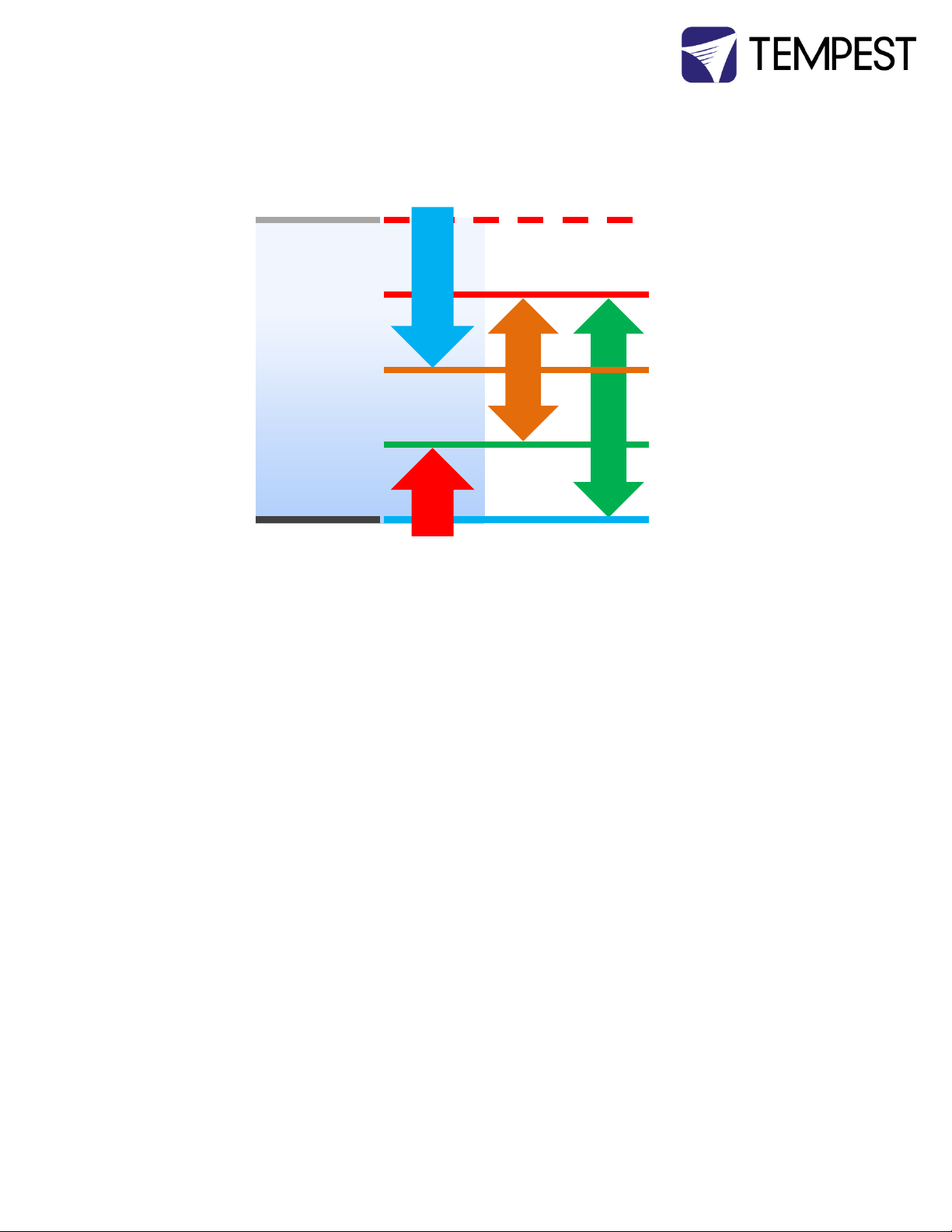
Trip Temp
(55-70˚C, Default 60 ˚C)
Upper Temp
(35-50˚C, Default 40 ˚C)
Trend Temp
(Dynamic)
IdealTemp (Dynamic, based
on Relative Humidity)
LowerTemp
(0-10˚C, Default 0 ˚C)
Cooling Fan(s)
Heater(s)
Relative Humidity
(50-90%,
Default 80%)
Low
High
DEC3.3 Control Parameters
Temperature and Humidity Ranges:
Notes:
1 In moving light enclosures the temperature sensor is located in the exhaust
airflow. Temperatures shown may be higher than those around the luminaire.
2 We recommend using the factory default settings for several weeks or months
before making any changes. In most cases they will not be necessary.
Max Humidity Range 50-90%, Default 80%
The threshold at which air inside the enclosure is heated to raise dewpoint and
prevent condensation. Setting a higher Max Humidity is not a bad thing in high-
humidity climates. Setting the Max Humidity too low will result in unnecessary
heating and excessive energy use. So set the Max Humidity at the top end of the
relative humidity likely to be experienced on site.
DMX Address Range 001-510, Default 001
Sets the DMX address for the lamp relay control. (See also DMX Response)
Set Temp Units Display Degrees Celsius or Fahrenheit. Default Celsius
Note that temperature settings must always be Celsius.
Lamp Hours Default 0000
Counts lamp hours – you must reset to zero when changing lamps.
Lamp On Point The lamp current at which DEC detects the luminaire/luminaire lamp is running.
Default is 1 Amp, which allows for equipment fans and power supplies to run
Cyclone Enclosure User Manual page 24
Page 25
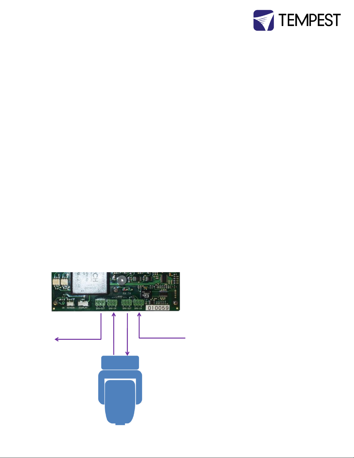
DMX IN from
outside world
DMX OUT to
next DMX device
❹ ❸ ❷ ❶
without changing the air in the enclosure. Lamp on point may be set in 0.2 Amp
increments between 0.2 Amps and 2.0 Amps.
Start-up Validation
When you switch power ON to the DEC3.3 controller (firmware 01.00.006 and up), the following
indications will confirm that the major system elements are working correctly:
BEEP! – a loud beep indicates that the processor has initialized and is functioning
correctly.
FANS – fans run for three seconds
HEATER – the heater turns on for 15 seconds. This is enough to get warm to the touch.
DMX Connections
DMX refers to USITT DMX512, a commonly used control protocol in the entertainment industry,
running over RS485. Consult USITT DMX installation guidelines when laying out a system, or
employ a qualified DMX system integrator.
A DMX network will be required if:
a) The luminaire inside the enclosure requires a DMX control signal
b) You wish to monitor the enclosure using RDM
c) You wish to control the enclosure lamp relay over DMX
DMX Terminations
Note: DMX will not normally be used in
luminaire installations.
Pinout: (1) Ground, (2) Data -, (3) Data +.
DMX Connectors:
1 DMX IN from network
2 DMX OUT to luminaire (or to network
if not controlling luminaire)
3 DMX IN from luminaire
4 DMX OUT to network
Cyclone Enclosure User Manual page 25
Page 26

+ ‒ G
+ ‒ G
+ ‒ G
+ ‒ G
Note: If the enclosed equipment does not use DMX, then connector (2) on the controller is DMX OUT
for the enclosure.
DMX Line Terminations
DMX cable runs must be terminated at the far end of the cable run with a termination resistor as
detailed in the DMX512 standard.
The individual equipment installed inside the
Tempest enclosures must NOT be terminated.
It is recommended that any line termination is
DMX OUT
DMX IN
LIGHT
DMX OUT
DMX IN
done using the 3-pin terminal connector fitted
to the DEC3.3 control circuit board.
LIGHT
Cyclone Enclosure User Manual page 26
Page 27
RDM is an effective and powerful
tool for commissioning and
monitoring an installation,
particularly in large systems. For
further guidance, please consult a
qualified RDM system integrator.
Tempest Lighting warrants DEC3.3
to be compliant with the RDM
standard, but is not an RDM
systems integrator, and can offer
only basic guidance on RDM
utilization.
Remote Device Management (RDM)
RDM refers to ANSI E1.20, a control protocol in the entertainment industry used for device
configuration and monitoring, and essentially an “extension” of DMX512. The use of RDM is
optional, and uses the same RS485 cable connection as DMX512, so no additional wiring is
required if DMX is already present. The user must ensure that any DMX splitters or other routing
devices used are RDM operable as well as DMX use. Tempest strongly recommends working with a
qualified RDM system integrator when designing an RDM network. Go to www.tempest.org for
contact information.
RDM and RDM Integration
DEC3.3’s RDM implementation allows system integrators to remotely configure, control or monitor
DEC3.3 attributes, including:
Relative Humidity
Air Temperature
PCB Temperature
Lamp Current
Elapsed Lamp Hours
Lamp Relay Status
Fan Relay Status
Heater Relay Status
DMX Status
DMX Start Address
DMX Personality (RDM Mode)
Device Type
Device Label
Software Version
Cyclone Enclosure User Manual page 27
Page 28
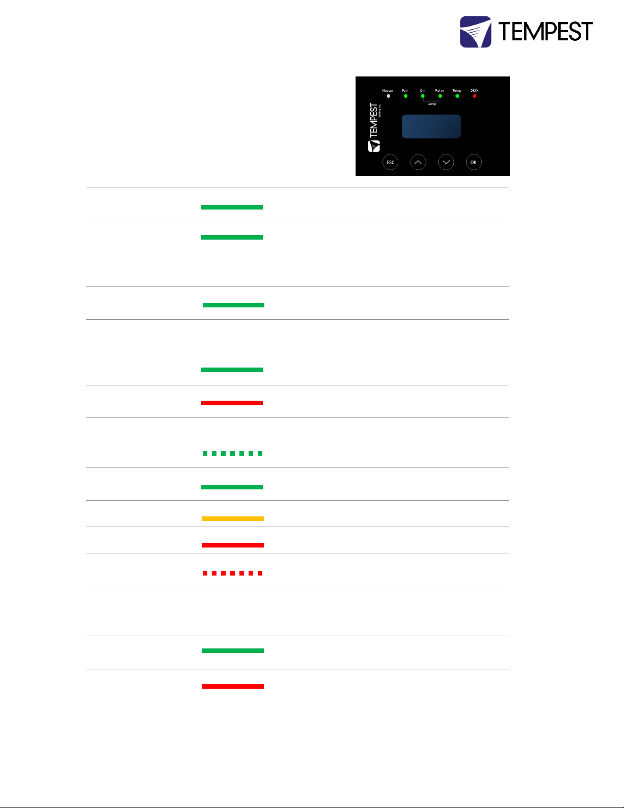
LED Indicators
Heater
ON (Green)
Heater is ON, to maintain lower temperature
level or to prevent condensation
Fan
ON (Green)
Lamp is ON, or Temperature is HIGH and
Fan is cooling enclosure. Short burst when lamp
off indicates fan moving air to stabilize
temp/humidity
Lamp On
ON (Green)
Current sensing shows lamp is ON
Lamp hour counter is running
OFF Current sensing shows lamp is OFF
Lamp hour counter is not running
Lamp Relay
ON (Green)
Lamp relay is closed (normal)
Luminaire power receptacle is energized
ON (Red)
Lamp relay is open due to over-temperature
event. Luminaire power receptacle is isolated.
Temp
FLASHING
(Green)
Temperature is below lower temp setting
ON (Green)
Temperature is in normal range
ON (Amber)
Humidity is above target limit
ON (Red)
Temperature is above top setting
FLASHING (Red)
Temperature is above Trip level
Luminaire power is isolated
DMX
OFF
DEC3.3 is in BASIC Mode – DMX not used. OR
DEC3.3 is in Monitor or Control Mode and no
valid DMX or RDM packet has been detected.
ON (GREEN)
Good DMX or RDM data packet received.
ON (RED)
Control Mode: DMX Fail. A previously good DMX
signal has failed.
Monitor Mode: No RDM information being
received (this is normal)
Control Interface
Tornado Enclosure User Manual page 28
Page 29
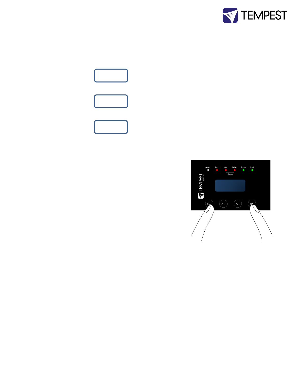
Control Display
The display on the Control display provides additional status information, depending on the
operating mode:
Basic Mode & 28˚C 47% internal temperature, relative humidity
Monitor Mode 209V OFF line voltage, lamp status
DMX Mode & 28˚C 47% internal temperature, relative humidity
Service Mode 209V OFF line voltage, lamp status
Alternating with:
DMX: 001 DMX Start Address
No DMX DMX Status
Control Interface Operation
The Control Interface is normally LOCKED.
To UNLOCK, hold ESC and OK together for 5 seconds.
You are now in the CONTROL MENU
Use to scroll up and down the menu.
Press OK to enter a menu item
Use to set the item parameter, or to scroll to the next menu level.
Use ESC to go BACK, and OK to confirm settings ( ).
To LOCK, hold ESC for 5 seconds.
Menu will time out after ten minutes.
Tornado Enclosure User Manual page 29
Page 30

Control Menu
SET DMX OPTIONS
SET DMX MODE
From the Front Panel, this menu item allows the user to check (and if necessary
change) the RDM mode.
BASIC Standalone operation, no DMX/RDM (factory default)
MONITOR Standalone, plus support for RDM remote configuration and
monitoring
CONTROL Monitor, plus use of a single DMX slot to control Lamp relay
SERVICE Monitor, plus use of three DMX slots to control Lamp, Heater and
Fan
Important: Please ensure that the DEC3.3 is NOT left in Service Mode.
SET DMX ADDRESS (in Monitor, Control or Service modes)
Select a DMX starting address in the range 001 to 510
1 – Lamp Relay
In Service Mode an addition two slots are available
2 – Fan Duty Control
3 – Heater Duty Control
Note that the DMX control is designed using a SAFETY pile-on Logic. So the DMX
input can only override automatic settings within safe limits.
SET DMX CURVE
DMX Curves affect the way the fixture relay is controlled in Control Mode.
DMX levels are shown as %.
Response Curve 1 (default)
DMX level 0-25 Relay disabled (open)
DMX level 26-75 No change to relay status
DMX level 76-100 Relay enabled (normally closed)
Response Curve 2
DMX level 0-19 No change to relay status
DMX level 20-40 Relay disabled (open)
DMX level 41-59 No change to relay status
DMX level 60-80 Relay enabled (normally closed)
DMX level 81-100 No change to relay status
Tornado Enclosure User Manual page 30
Page 31

SET DMX RESPONSE
DMX Response sets a delay time before DMX Control Mode settings are acted on.
Setting a response delay of a few seconds would prevent unintended fixture relay
state changes in the event of a short accidental change in DMX level.
NOTE: from firmware revision 0.00.100, DEC holds last valid DMX level if DMX is
interrupted.
Response Delay Values are:
No Delay (default), 1, 2, 5, 10, 15, 20, 30, 60 seconds.
SET TEMP UNITS
Choose to display temperature values in Celsius or Fahrenheit (default Celsius)
Note that temperature settings must be entered in Celsius.
SET TEMP RANGES
Set three temperature trigger points for Bottom, Top and Trip temperatures, in °C.
SET TEMP LOWER (minimum temperature to be maintained)
(default 0°C, permissible range 0-10°C).
SET TEMP UPPER (maximum desired temperature)
(default 40°C, permissible range 35-50°C).
SET TEMP TRIP (temperature at which load will be isolated – see note)
(default 60°C, permissible range 55-70°C).
Note: A thermal emergency is when enclosure ventilation fails with the lamp on, in which case the
temperature will rise very quickly. To avoid nuisance tripping we recommend setting a higher Trip
temperature, 60°C or above.
SET MAX HUMIDITY
(default 80%, permissible range 50-90%).
Set target maximum relative humidity level. This should be set at or a few % higher than
the normal high humidity levels expected on site.
SET LAMP ON POINT
The lamp current at which DEC detects the luminaire/luminaire lamp is running. Default is
1 Amp, which allows for equipment fans and power supplies to run without changing the
air in the enclosure. Lamp on point may be set in 0.2 Amp increments between 0.2 Amps
and 2.0 Amps.
RESET LAMP HOURS
Reset each time you change the lamp in the luminaire/luminaire.
Make this a part of your maintenance instructions.
Tornado Enclosure User Manual page 31
Page 32
STATUS DISPLAY
View current status information, using the arrow keys to scroll through:
a) Humidity – relative humidity in %
b) Air temperature, in degrees C or F
c) PCB temperature (this will usually be significantly higher than air temperature)
d) Voltage – line Voltage reaching the DEC
e) Current being drawn by luminaire/light, in Amps
f) Lamp Hours elapsed since last reset
g) Firmware version
RDM Monitoring and Configuration
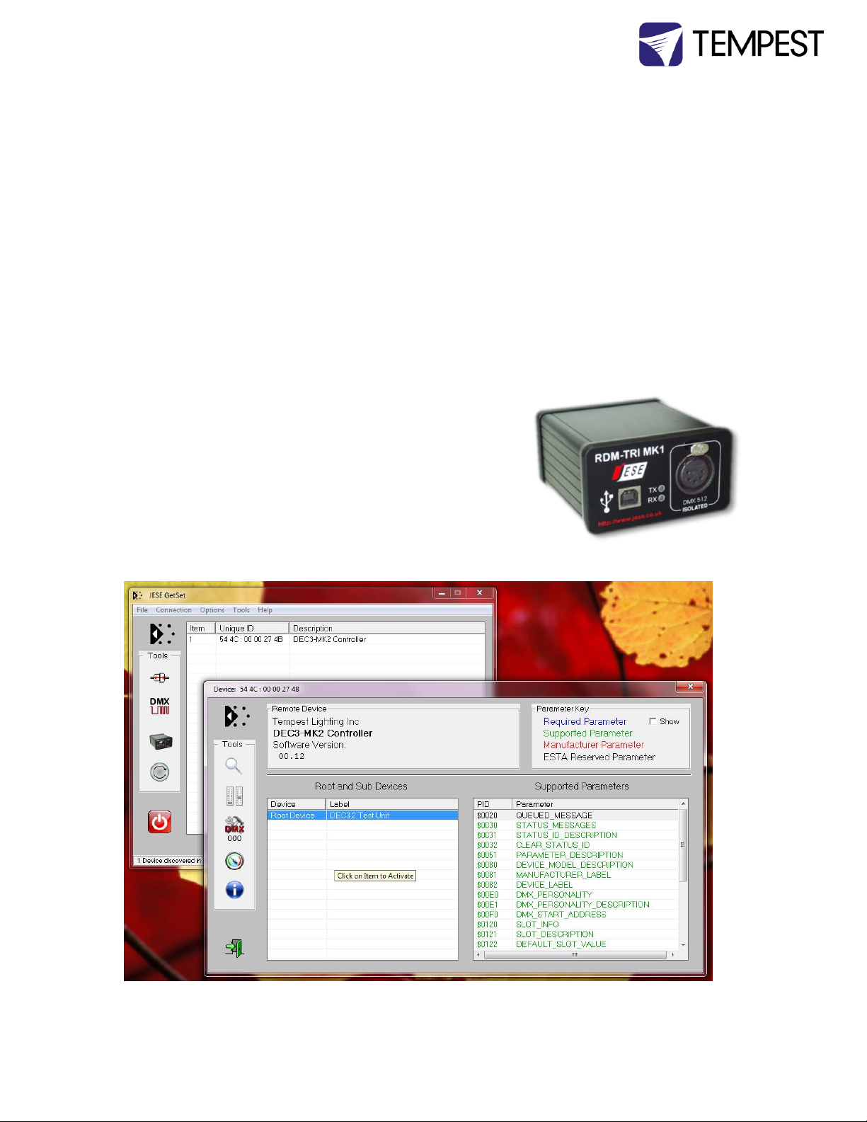
All the features accessible over the DEC3.3 control panel are
also available over RDM. Just how this information is displayed
will depend on the RDM interface used. These screen shots
were taken running the GetSet program in Windows 7, and
connecting to a DEC3.3 controller using a RDM TRI MK1
interface, Tempest part # 2000.190
GetSet gives you a powerful RDM front end suite, with Tempest-specific functions and displays.
Tornado Enclosure User Manual page 32
Page 33
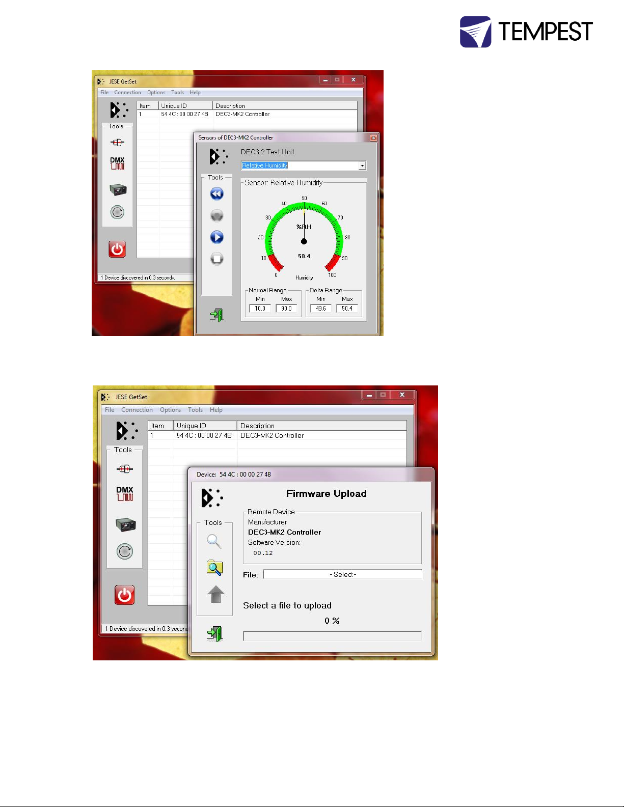
This view shows a single
DEC3.2 test unit that has been
correctly discovered and
labeled by the GetSet software
suite, and a log of RDM
messages.
This RDM interface provides a
graphic view of the various
sensor functions supported by
DEC3.2 and up
Important:
Check that your RDM interface
vendor has tested his interface
with Tempest enclosures and
all other RDM devices you plan
to use on the same network.
Firmware Upgrade over RDM
DEC3.3 firmware
is field-
upgradeable,
using RDM. A field
upgrade requires a
JESE RDM TRI MK1
interface to be
connected to the
DMX network on
which the DEC3.3
is located, and the
use of JESE GetSet
software. The kit
is available from
Tempest under
part # 2000.190.
Tornado Enclosure User Manual page 33
Page 34
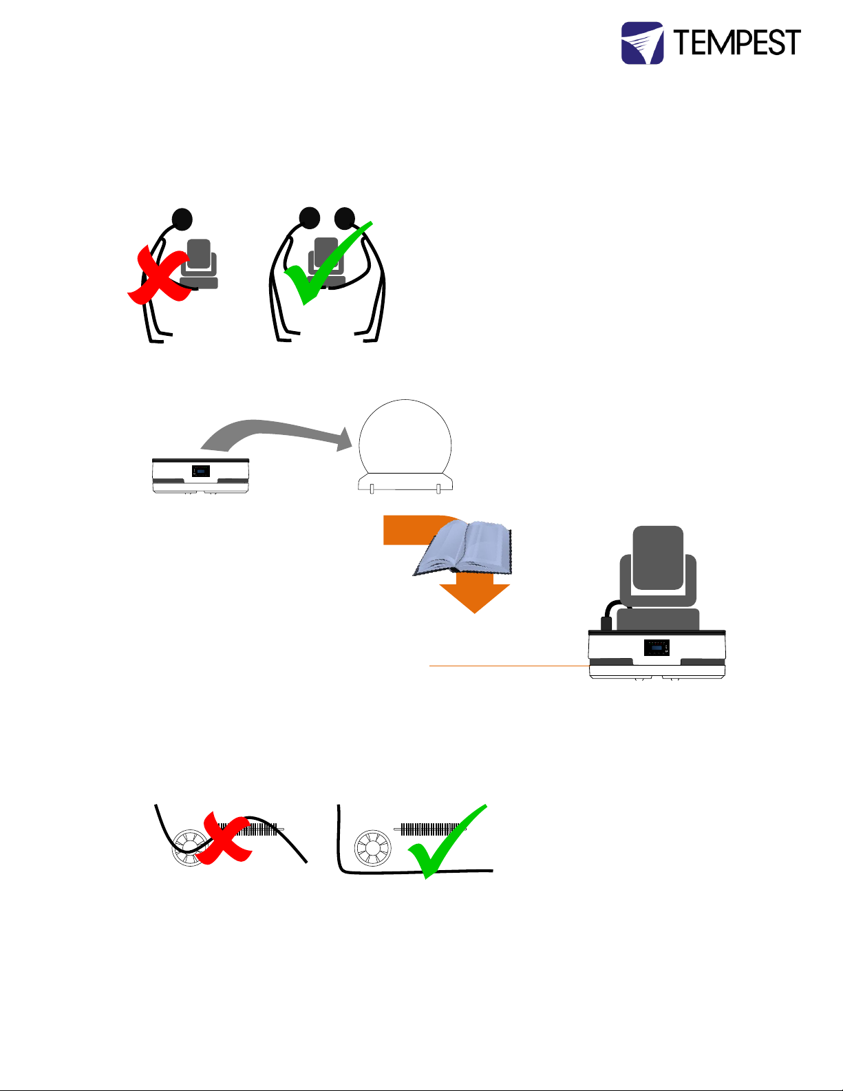
5 Mounting the Luminaire
Do not attempt to mount the luminaire with only a single person.
1 Remove the globe and place it in a safe location.
2 Follow the instructions below for
different luminaire types
3 Plug the luminaire into the power receptacle in the enclosure, and
then connect the DMX cables to the luminaire
4 Tie down cables (to the luminaire or enclosure base) so that they will not come into contact with
the heater or fans at any point.
Tornado Enclosure User Manual page 34
Page 35
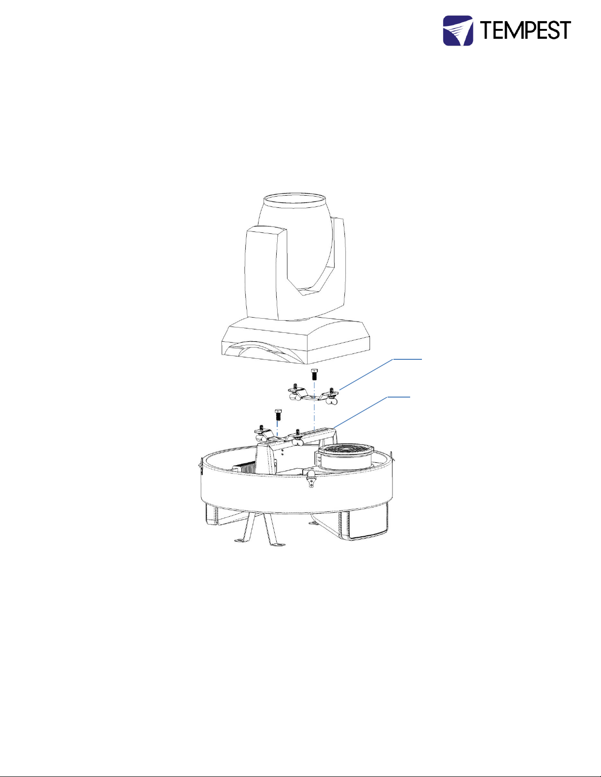
Tornado 1900-1950
Mount the luminaire on its omega clamps on the fixture mounting Bracket.
Note: Depending on the size of the fixture base, it may be easier to remove the fixture bracket before
attaching the omega clamps and luminaire.
Omega Clamp
Fixture Mounting
Bracket
Tornado Enclosure User Manual page 35
Page 36
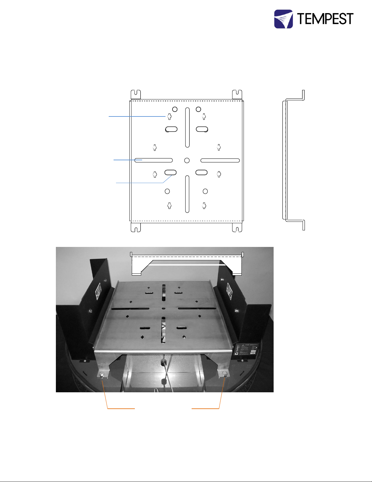
Tornado 2000, 2100, 2200, 2300
Fixture Tray
Use either the
vertical or
horizontal slots for
Omega Clamp and
VL clamp bracket
fixings
Use the obrounds
to mount Martin
MAC3 direct to the
Fixture Tray
Use the keyholes to
mount Robe
fixtures without
Omega Clamps
Remove the Fixture
Tray by removing
the four 5/16”
mounting bolts
Tornado Enclosure User Manual page 36
Page 37
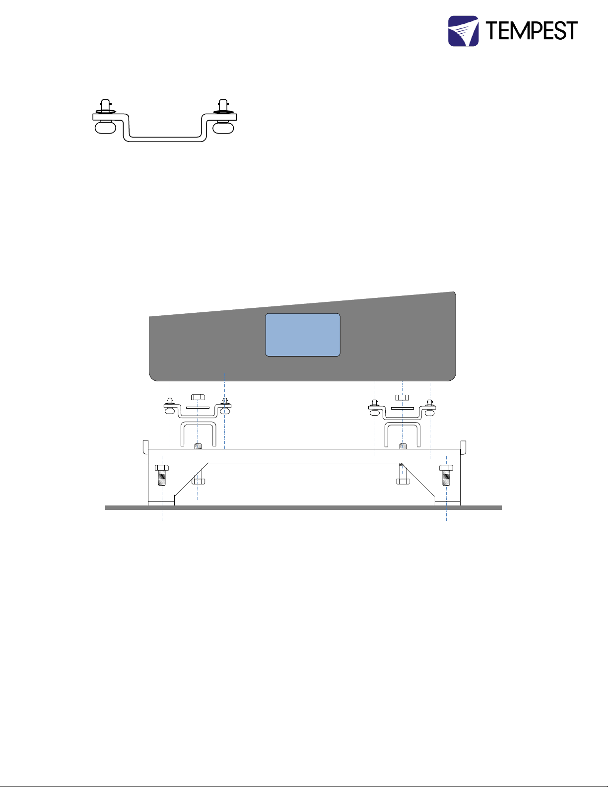
Luminaires with Omega Clamps
This applies to most luminaire types:
1. Remove the Fixture tray from the enclosure, as shown above.
2. Mount the Omega clamps securely onto the fixture base. Make sure that the fasteners lock
positively in place.
3. Bolt the clamps to the fixture tray, using the Omega Clamp Spacers and the bolts provided.
CHECK THAT THE FIXTURE IS CENTERED ON THE FIXTURE TRAY.
4. Replace the fixture tray/fixture assembly in the enclosure, and bolt firmly in place.
Diagram – Mounting with Omega Clamps and Clamp Spacers
Fixture Tray
Omega clamp –
orientation may
Fixture
Tray Bolts
Bolt clamp
in place
Omega
Clamp
Tornado Enclosure User Manual page 37
Page 38
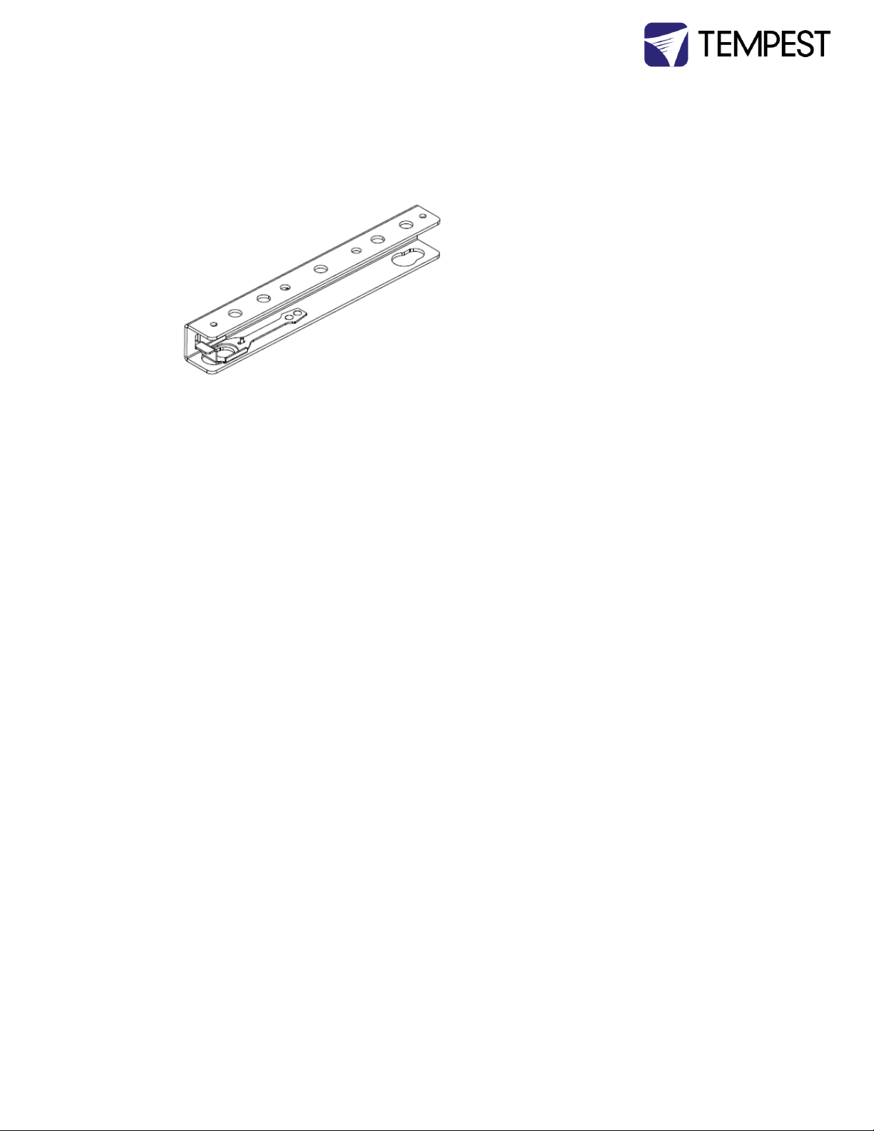
Vari*Lites and the Vari*Lite Hook Bracket
Vari*Lites are provided with a Hook Bracket in place of an Omega Clamp.
1. Attach the Hook Bracket to the VL
fixture feet, following instructions provided by
Vari*Lite.
5. Remove the Fixture tray from the enclosure, as shown above.
6. Bolt the Hook Brackets to the fixture tray, using the bolts provided. CHECK THAT THE
FIXTURE IS CENTERED ON THE FIXTURE TRAY.
Replace the fixture tray/fixture assembly in the enclosure, and bolt firmly in place.
Tornado Enclosure User Manual page 38
Page 39
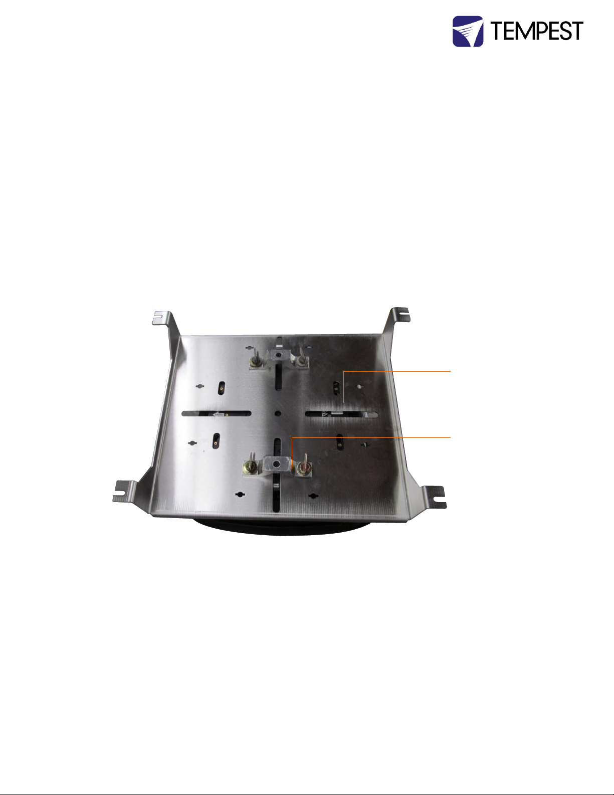
Martin MAC III and other tall Luminaires
The MACIII is too tall to use in a Tornado 2300 with Omega Clamps installed in the usual way. In this
case, and in similar cases, the fixture must be secured in place with the omega clamp BELOW the
fixture tray.
1. Remove the Fixture tray from the enclosure, as shown above.
2. Carefully place the fixture on its side on a flat surface, and identify the mounting holes in the
Fixture Tray that line up with the fixture mounting locations.
3. Fit the quarter-turn fasteners through the Fixture Tray into the receptacles in the fixture
base:
4. Mount the omega clamp into the quarter-turn sockets in the fixture base, through the holes
provided in the fixture tray.
5. Make sure that all quarter-turn fasteners are fully rotated (clockwise) and positively locked,
and that the luminaire is firmly attached to the fixture tray
6. Replace the fixture tray/fixture assembly in the enclosure, and use the 5/16 bolts provided
to secure firmly in place
Fixture Tray
Fixture Omega
Clamp
Tornado Enclosure User Manual page 39
Page 40
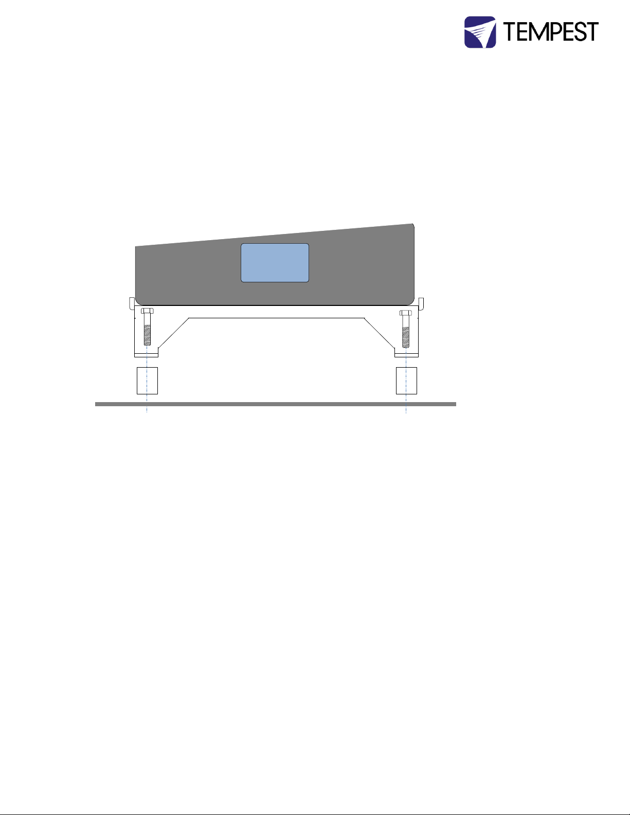
Shorter Luminaires Requiring Bracket Standoffs
In order to align the center of the luminaire correctly in the Tornado enclosure, some fixtures need the
Fixture tray to be raised. This is done with tubular standoffs that insert between the Fixture Tray and
the enclosure Base. The installation procedure is the same as for any of the above, except that the
fixture standoffs must be inserted when the Fixture Tray is remounted.
If the fixture you specified when you ordered your Tornado enclosure requires bracket standoffs, they
will have been supplied. If none are supplied, your fixture does not require them.
Diagram – Fixture Tray Standoffs
Fixture
Tray
Use longer
bolt
provided
to fix
Tornado Enclosure User Manual page 40
Page 41
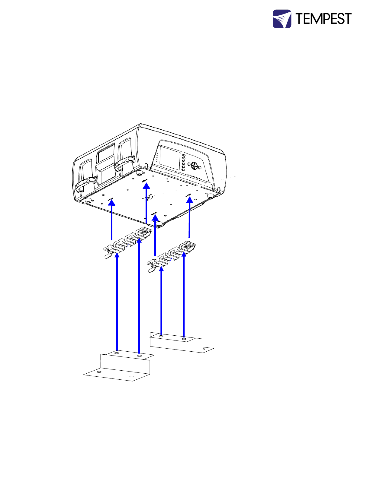
Mounting the Luminaire – Tornado 2400
The Tornado 2400 is designed to house the Barco/High End Systems Showgun, Showbeam, Showpix
and DL3 luminaires, all of which have the same base.
The Tornado 2400 is supplied with two heavy-duty mounting brackets, which bolt to the extruded
clamps supplied with the Showgun/Showbeam/DL3 fixture.
Mount the clamps to the enclosure brackets, then set the fixture on the clamps and secure using the
quarter-turn fasteners provided.
Note: DML1200 Fixture: When the Tornado 2400 is specified for the Barco DML1200, it will be supplied
with a custom fixture mounting plate that bolts directly into the fixture base.
Tornado Enclosure User Manual page 41
Page 42
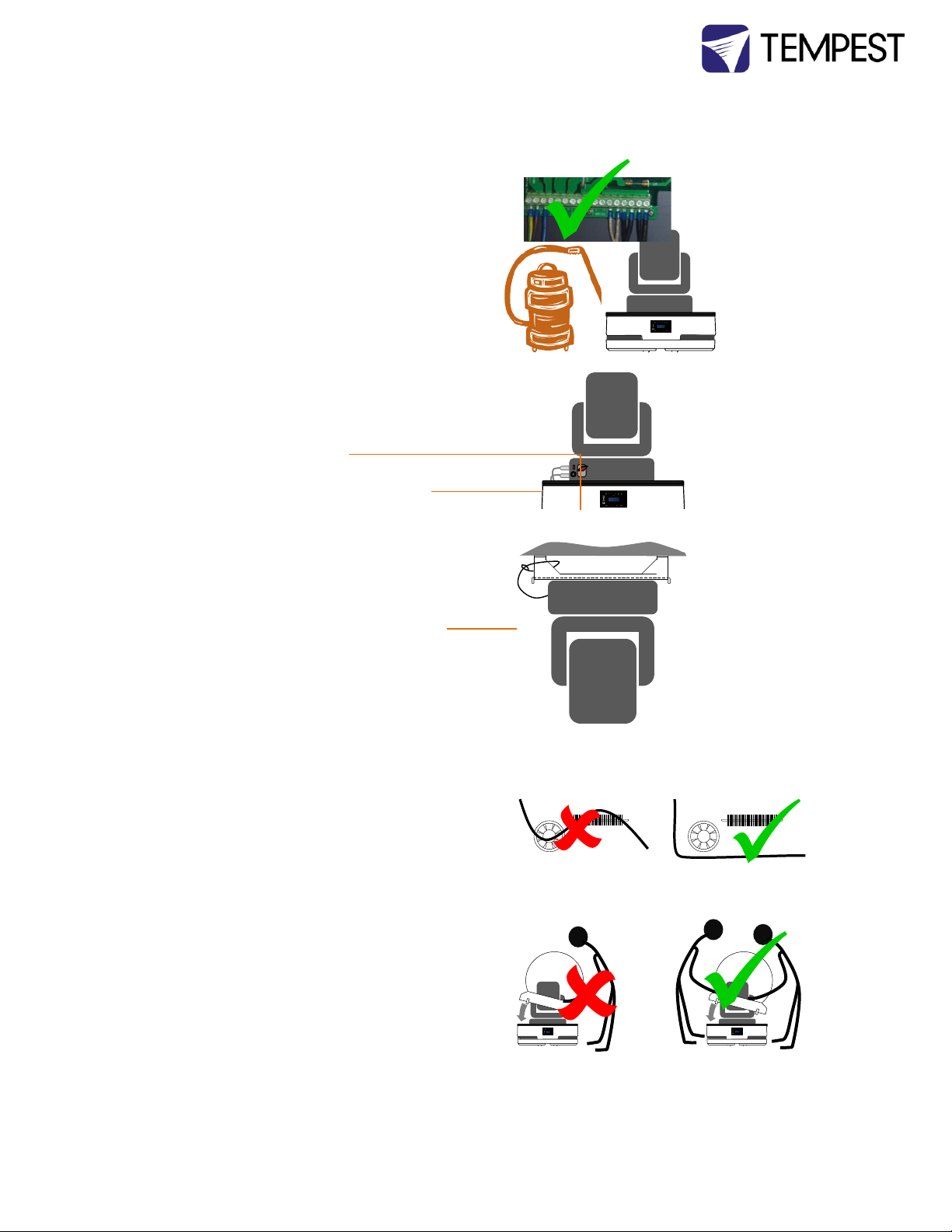
6 Closing up the
Enclosure
1 Check all electrical connections
2 Clear the enclosure and luminaire of all dust
and debris.
3 Check that the power switch on the
luminaire is in the ON position.
4 Complete DMX control connections,
following luminaire manufacturer’s
instructions.
5 Test luminaire
6 Safety cable the luminaire to the Fixture Tray
leg (horizontal and vertical enclosures).
7 Tie down cables (to luminaire or mounting
brackets) so that they will not touch heaters
or fans.
8 Replace the globe assembly on the Tornado
base. This requires two people.
Tornado Enclosure User Manual page 42
Page 43
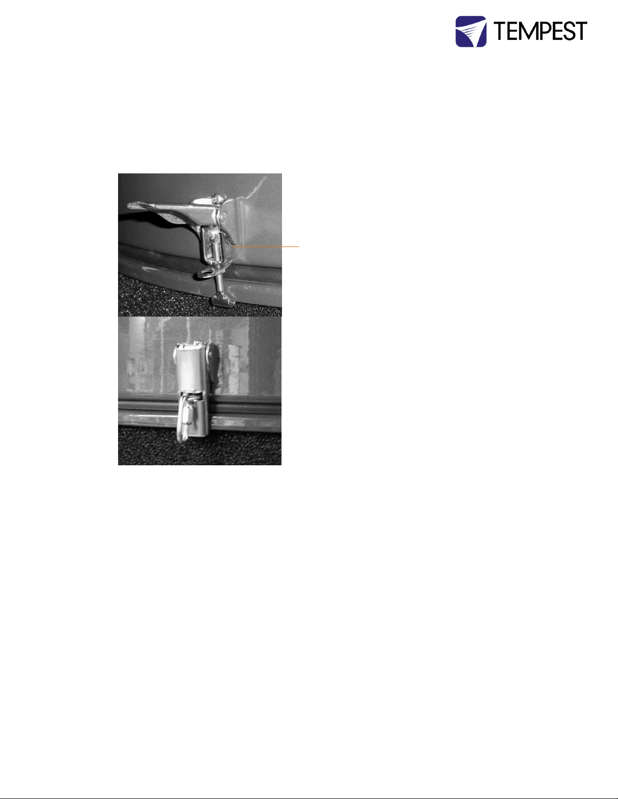
Securing the Globe to the Tornado Enclosure Base
1. Using two people, lift the globe assembly in place.
2. As soon as the globe assembly is in place, secure the four latches, and insert padlocks in the
locking rings, if required, for additional security.
3. IMPORTANT: The latch tension is adjustable, and has been set in the factory to assure a
secure and weathertight seal. Check to make sure the tension is maintained.
4. Security – use a caribiner or a padlock (not supplied) for additional security if desired.
Congratulations! Your system is now ready to check out.
Latch properly secured, with a
caribiner in place.
Tension adjustment screw and
locknut.
Tornado Enclosure User Manual page 43
Page 44

7 Operation
Enclosure must receive power at all times. It is an active, climate-controlled enclosure, and will
not provide proper protection for the luminaire inside if it is not connected to AC power.
Unless the enclosure or luminaire is undergoing routine maintenance, the globe should be in
place and locked down at all times.
Only authorized personnel should open the enclosure (see maintenance warnings in the next
section).
If the ambient temperature is high enough, the over-temperature shutdown feature may engage
and temporarily cut off power to the luminaire. Once the temperature reaches acceptable levels,
power will be automatically restored.
Do not routinely operate luminaire in full sun in warm weather. Black luminaires absorb a
significant amount of energy from the sun and may overheat in these conditions. The enclosure
has not been designed to protect the luminaire when running in this kind of extreme condition
(outside lighting is generally used at night).
Tornado Enclosure User Manual page 44
Page 45

8 Routine Maintenance
It is very important to perform routine maintenance on both the enclosure and the luminaire within.
Failure to do so may reduce lifetime for both the enclosure and the luminaire.
Note
Maintenance schedules depend on location and environment. The times given here are general
guidelines for you to use. It is up to you to judge whether maintenance should be done more often. We
do advise doing these tasks no less often than mentioned here.
Safety
Although maintenance can be performed while the enclosure is powered, it is safer to carry it
out with the power disconnected with proper lockout and tag out procedures followed.
Be aware that once the enclosure has had power applied to it, the heater will get hot and the
fans will start to turn. Make sure that your hands are clear of these areas before applying power to the
enclosure.
Only authorized personnel should perform maintenance on the enclosure or luminaire
Do not service the unit in the rain or other adverse weather conditions (snow, sleet, high
winds, etc.).
Be aware that the globe is a large object that can be awkward to handle, especially when
standing on a ladder or scaffolding.
Inspection Checklist: - Every Three (3) Months
All weep (drain) holes should be clear
All vents should be free of debris
Enclosure should be free of debris both inside and out
Bolts should be tight
All safety cable should be in good condition
Lid seal should be in good condition, Check seal inside and out for gaps.
Globe should not be cracked
Fans should be moving (it will be necessary to have the power on to check this), with
corresponding indicator status
Except for the last two items (concerning globe and fan), problems with any of these things
can be easily remedied. Contact technical support for problems with the last two items.
Air Filters - Every Three (3) Months
The air filters all around the base should be removed and cleaned on a regular basis. To
remove filters, pull them directly out of their grooves. The filters can be cleaned by running water from
a hose and do not require any special solution.
To reinstall, push filter back into place between the top and bottom base covers.
Case and Globe - As Needed
The outside of the case and globe should be cleaned as needed. Outside inspection should
give you a good idea of when this is necessary. The case should be cleaned with a wet cloth and mild
detergent (if necessary). Do not use a direct spray from a hose to clean the case. The globe can be
Tornado Enclosure User Manual page 45
Page 46

cleaned with any mild cleaner. It is also acceptable to treat globe with a product that keeps rain from
adhering to its surface.
DO NOT USE hydrocarbon-based cleaners on the globe under any circumstances. They can severely
damage the globe material.
Luminaire
Review the manufacturer's instructions for proper maintenance of your luminaire. Remember,
the enclosure simply protects the luminaire and is not a substitute for regular maintenance.
Tornado Enclosure User Manual page 46
Page 47

9 Troubleshooting
This is a guide to the general symptoms, problems, and solutions that may occur during the lifetime of
your enclosure. However, it is important to remember that problems may occur within the luminaire
itself and these must also be considered.
Luminaire does not have power.
Check power switch of luminaire. (Note: the following actions should be performed by a
licensed electrician) If power is on, check wiring (including metering supply voltages,
enclosure must receive 200-240VAC to operate properly). If LEDs on the DEC3 control panel
controller are lit, check the Lamp Relay LED. If it is on, meter power in receptacle. If no
power is present at the receptacle, contact technical support.
If DEC controller is set to DMX mode, check that a DMX address has been set and that the
DEC is receiving a valid DMX signal with the appropriate channel HIGH.
If using SPLIT POWER FEEDS, check that both the MAIN and SPLIT feeds are energized.
In case of over-temperature, the power disconnection is an intended function of the
enclosure and is for the protection of the luminaire, which is not meant to operate in
extreme conditions. In this case, the problem will only continue until temperature drops to
acceptable levels. It is possible that the air intake or exhaust has become clogged, leading to
higher temperatures inside the enclosure. Make sure that these areas are clear, the filters
are clean, and the fans are working properly.
Luminaire turns on and off repeatedly
Check that vent areas and airways are clear. If so, ambient temperature may be too high (see
over-temperature note above) or luminaire may have internal problem.
Luminaire does not respond to DMX signal.
Make sure that luminaire has power. If so, check DMX wiring. If not, see above.
Fans are not spinning.
Fan cords may have become disconnected. Check connections between fan and cord.
Fans may be obstructed. Shut off power to enclosure and check for obstructions. Turn power
back on to see if fans will start spinning. If fans do not turn and display on temperature
controller is lit, contact technical support. If fans do not turn display is not lit, then enclosure
is not receiving power. Turn off all power and check wiring. If the wiring is correct, contact
technical support.
Excessive debris in unit.
Filter may not be fully pushed into groove. Make sure that it is in place around the whole
unit.
Excessive water in enclosure.
Weep (drain) holes may be clogged. Clear them.
Tornado Enclosure User Manual page 47
Page 48

Latches do not latch properly.
Closure of globe may be obstructed. Check to make sure seals are clear before replacing
globe.
Tornado Enclosure User Manual page 48
Page 49

10 Limited Warranty
All sales are subject to the company’s Standard Terms and Conditions, available for download at
www.tempest.org. The following is an extract.
INSPECTION/WARRANTY/RETURNS.
A. Customer, at its sole expense, shall inspect all Goods promptly upon receipt and accept all Goods that conform
to the specifications or catalog. All claims for any alleged defect in or failure of the Goods or Seller's performance to
conform to the Contract, capable of discovery upon reasonable inspection, must be set forth in a written rejection
notice detailing the alleged non-conformity, and be received by Seller within thirty (30) calendar days of Customer's
receipt of the Goods. Failure by Customer to notify Seller of the alleged non-conformity within thirty (30) days will
be conclusive proof that the Goods have been received by Customer without defects or damage, and in the
quantities specified on the bill of lading and shall constitute an irrevocable acceptance of the Goods and a waiver of
any such claim in connection with the Goods.
B. Seller warrants to Customer only that the Goods will be free from defects in material and workmanship at the
time of delivery and, subject to the exceptions and conditions set forth below, for the following period (the
"Warranty Period"): twelve (12) months from the date of shipment by Seller. Seller may provide additional years of
warranty coverage beyond 12 month, at the rate of 2.5% of the net sale price per year, up to a total of four
additional years’ coverage beyond the standard 12 month warranty period. Seller will remedy a defect as set forth in
paragraph 7 D, below, (the "Warranty"). The Warranty is subject to each of the following exceptions and conditions:
1. Customer must promptly (and in all events within the Warranty Period) notify Seller of any alleged defect in a
written notice (the "Notice") which shall set forth the quantity, catalog number, finish, original purchase order
number, Seller's invoice number on which Goods were originally billed and a statement of the alleged defect, along
with digital photographs showing such defects where feasible.
2. The Warranty shall not apply: (i) to any claimed defect that was capable of discovery upon reasonable inspection
and deemed to be waived under paragraph A, above; (ii) to any Goods that have been subject to misuse, abnormal
service or handling, or altered or modified in design or construction; (iii) to any Goods repaired or serviced by any
person other than Seller's authorized service personnel or to Goods installed other than according to installation
instructions, or (iv) with respect to normal wear and tear.
3. Seller makes no Warranty with respect to parts or components that are not the product of Seller, and specifically
makes no warranty whatsoever for equipment housed inside enclosure products manufactured by Seller.
4. The Warranty is Seller's exclusive warranty with respect to the Goods. Seller makes no warranties, guarantees or
representations, express or implied, to Customer except as set forth in this section. ALL OTHER WARRANTIES,
EXPRESS OR IMPLIED, INCLUDING, WITHOUT LIMITATION ANY IMPLIED WARRANTY OF MERCHANTABILITY OR OF
FITNESS FOR USE OR FOR A PARTICULAR PURPOSE, ARE HEREBY EXCLUDED AND DISCLAIMED.
C. Seller will accept the return of Goods properly rejected under paragraph A, above, or as to which Notice of an
alleged breach of Warranty has been timely given and such Goods may be returned to Seller, freight prepaid, but
only upon Customer's receipt of Seller's written return material authorization ("RMA") and shipping instructions. The
RMA shall be void if the Goods are not received within 45 days after issuance of the RMA. No deduction or credit in
respect of any rejected or returned Goods shall be taken until Customer has received Seller's further written
deduction or credit/authorization following Seller's inspection to confirm nonconformity or defect. Seller will charge
to Customer any and all costs incurred by Seller in connection with the handling, shipping, inspection and
disposition of any returned Goods that are determined by Seller not to have been nonconforming upon Delivery or
as to which the warranty hereunder is not applicable.
D. UPON ANY PROPER RETURN PURSUANT TO PARAGRAPH C, ABOVE, WHETHER IN CONNECTION WITH A REJECTION
OF GOODS OR AN ALLEGED BREACH OF WARRANTY AND BASED UPON THE CONDITIONS SET FORTH IN THIS
PARAGRAPH 7, SELLER AGREES THAT IT WILL, AS THE SOLE AND EXCLUSIVE REMEDY UNDER THE CONTRACT OR
OTHERWISE, FOR ANY NONCONFORMITY OR BREACH OF WARRANTY, AND AT SELLER'S SOLE ELECTION: (i) REPAIR
SUCH GOODS; OR (ii) REPLACE SUCH GOODS.
Tornado Enclosure User Manual page 49
Page 50

11 Tempest Product Support
Step 1: First contact your local Dealer for support. Your dealer is best placed to respond quickly to
your needs.
Step 2: If your dealer is unable to answer your questions please contact
Tempest Lighting
13110 Saticoy Street
North Hollywood, CA 91605, USA
Tel +1 818 787 8984
Fax +1 818 982 5582
[email protected]
Visit our web site for current information and specifications:
www.tempest.org
Tornado Enclosure User Manual page 50
 Loading...