

Tempest BD-24-H-6.5, BD-27-H-9.0, DD-16-H-5.5, DD-18-H-5.5, DD-21-H-6.5 Operation Manual
...Page 1
POWER BLOWERS®
Operations
Manual
2012 Version
GASOLINE
Direct-Drive
Belt-Drive
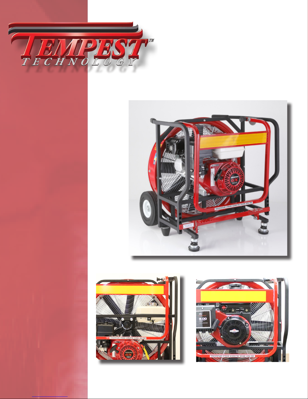
Tempest Gasoline Direct-Drives
(Honda)
Tempest Gasoline Belt-Drives
Tempest Gasoline Direct-Drives
(Briggs & Stratton)
Page 2
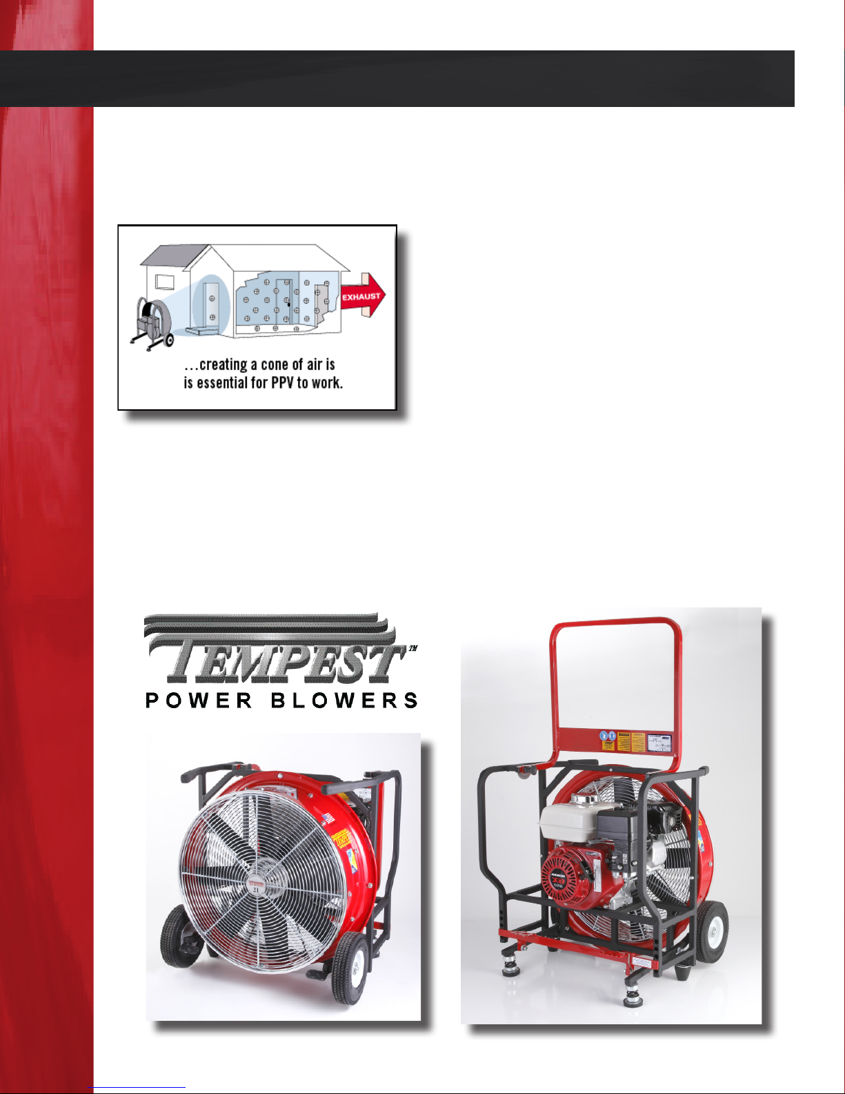
Introduction
TEMPEST TECHNOLOGY CORPORATION® is the leading manufacturer of products
and accessories for environmental management in reghting and industrial applications.
TEMPEST® has expanded into other industries and found new applications for its
products. e TEMPEST POWER BLOWER® and PPV/PPA are used by construction
contractors to control dust, fumes and unhealthy gases like carbon monoxide, greatly
improving safety in conned spaces.
TEMPEST® began as a manufacturer of gasoline
and electric powered blowers for the re service.
ese departments use the TEMPEST POWER
BLOWER® to provide “Positive Pressure Ventilation / Attack”(PPV/PPA) to remove heat, gases
and smoke from the interior of a burning structure.
TEMPEST TECHNOLOGY CORPORATION® has earned a reputation as a leader and
innovator in the air movement industry and continues in that role today.
Page 1
Page 3

About This Manual
is manual is produced solely for the use of purchasers and operators of TEMPEST
TECHNOLOGY CORPORATION® equipment. Any reproduction, retransmission, or
other use of the contents of this manual without written consent of TEMPEST TECHNOLOGY CORPORATION® is strictly prohibited.
It is the intent of this manual to provide the owner/operator of TEMPEST® products
with both general and specic information regarding the safe and proper operation and
maintenance of the equipment described within.
CONTACT:
If aer careful review, any questions arise concerning any portion of this
manual, please contact TEMPEST TECHNOLOGY CORPORATION® for
assistance:
TEMPEST TECHNOLOGY CORP.®
4708 N. BLYTHE AVENUE
FRESNO, CA 93722
Toll Free: 800.346.2143
Phone: 559.277.7577
Fax: 559.277.7579
E-MAIL: [email protected]
WEB PAGE: www.tempest-edge.com
Page 2
Page 4

Table of Contents
INTRODUCTION 1
ABOUT THIS MANUAL 2
CONTACT INFORMATION 2
SAFETY GUIDE 4
GENERAL INFORMATION 5
BLOWER IDENTIFICATION 5
SERIAL NUMBER LOCATION 5
WARRANTY 5
POWER BLOWER DATA 6-7
POWER BLOWER INFORMATION 8
OPERATING PROCEDURES 9-11
PRE OPERATION 9
VISUAL INSPECTION 9
ENGINE OIL 9
RECOMMENDED OILS 9
FILLING THE CRANKCASE 9
FUEL 10
OPERATION 11
SET-UP 11
STARTING 11
STOPPING 11
MAINTENANCE PROCEDURES 12-16
OIL CHANGE 12
AIR CLEANER 12
CLEANING AIR FILTER ELEMENTS 13
COOLING SYSTEM 13
SPARK PLUG 13
CARBURETOR 14
EMISSION CONTROL SYSTEM 14
BLADE REMOVAL AND INSTALLATION 14-17
BLADE REMOVAL 18”-27” 15
BLADE INSTALLATION 18”-27” 15
BLADE REMOVAL 16” 16
BLADE INSTALLATION 16” 16-17
MAINTENANCE SCHEDULE 17
BELT ADJUSTMENT 18
BELT REPLACEMENT 18
TROUBLE SHOOTING 19
BLOWER FAILS TO START 19
POOR BLOWER PERFORMANCE 19
BLOWER MOVEMENT OR “WALKING” 19
NOTES 20-22
DIRECT-DRIVE POWER BLOWER EXPLOSION VIEW 23
DIRECT-DRIVE POWER BLOWER PARTS LIST 24
BELT-DRIVE POWER BLOWER EXPLOSION VIEW 25
BELT-DRIVE POWER BLOWER PARTS LIST 26
Page 3
Page 5

Safety Guide
Failure to follow the operating, maintenance and lubrication requirements set forth in
this Operation and Maintenance Manual may result in serious personal injury and/or
damage to equipment.
e following WARNING statements indicate potentially hazardous conditions for operators and equipment. Make certain that anyone who works on or around the blower
has read and fully understands the safety precautions listed.
1. Carefully read this Operation and Maintenance Manual before attempting to
operate, service or disassemble any part of your TEMPEST POWER BLOWER®.
2. DO NOT operate the unit when mentally or physically fatigued or impaired.
3. Stay away from rotating parts; avoid wearing loose jackets, shirts, and ties. Keep
hands and feet away from the blower.
4. Keep all unauthorized personnel at a safe distance from the blower.
5. Keep all guards in place. DO NOT make repairs while the unit is running. DO
NOT operate if any guard or grill is not in place.
6. Always wear eye protection. Loose debris can be picked up in the air
stream and own in the air.
7. Hearing protection is required. Motor and air noise may exceed safe dB levels.
8. Gasoline is extremely ammable and is explosive under certain conditions.
To prevent re hazards, do not place ammable objects close to the engine.
9. Do not overll the fuel tank. Aer refueling, make sure the tank cap is closed
properly and secured. If any fuel is spilled, make sure the area is dry before start ing the engine.
10. Never operate gasoline-powered blowers in an enclosed or conned area. Ex haust contains poisonous carbon monoxide gas; exposure may cause loss of con sciousness and may lead to death.
11. e muer becomes very hot during operation and remains hot for some time
aer stopping the engine. Be careful not to touch the muer while it is hot. To
avoid severe burns or re hazards, let the engine cool before transporting or stor ing the unit.
12. It is the sole responsibility of the owner/operator to develop and practice the
proper use of the TEMPEST POWER BLOWER® in accordance with generally
accepted ventilation procedures as well as the department’s own operating proce dures before placing the unit into service.
Page 4
Page 6
General Information
Blower Identication
Each TEMPEST POWER BLOWER® has a model number as well as a serial number. e
model number signies information such as blade diameter, engine type and horsepower. e serial number relates to information referencing the date of manufacture. is
information is useful should it become necessary to contact the factory regarding your
Power Blower.
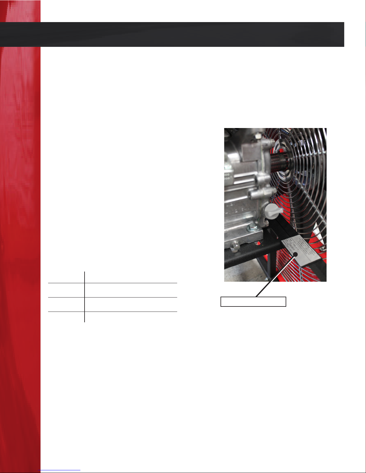
SERIAL NUMBER LOCATIONS
BELT-DRIVE and DIRECT-DRIVE GASOLINE POWERED UNITS:
e serial number is located on a small plate
welded to the frame.
Please write the Serial Number of your TEMPEST POWER BLOWER® in the spaces
below. is will aid us in identifying which
model you have when assisting you.
Model
Date
Blower Identication
Serial No.
is plate/information may be
located on the le or right side
of the Blower.
Warranty
Please visit www.tempest-feedback.com to complete your warranty information
and activate your warranty.
Page 5
Page 7

Power Blower Data
TYPE:
Positive Pressure Ventilator
BLADE:
Air Flex Fiberglass Reinforced Polyamide
BUSHING:
Keyed Sha and Set or Cap Screws.
SHROUD:
Turbo 2000 Tapered Aluminum.
DRIVE:
Industrial-Type, Straight-Banded V-Belt (On Belt-Drive Blowers) or Direct Drive
(On Direct Drive Blowers).
BEARINGS:
Locking, Self-Aligning and Permanently Lubricated.
FRAME:
Rugged, Lightweight, Square-Steel Tubing with Powder-Coat Finish.
TILT MECHANISM:
Patented Five-Positions, Foot-Operated Tilt Mechanism (e Winning Step).
GRILL:
Continuous Circular-Wound, External-Weld Steel Wire with 8 Tie Points for Ad ditional Safety.
VIBRATION DAMPENERS:
Steel-Reinforced Rubber.
GAS ENGINES:
TYPE: Single Cylinder, 4 Stroke, Gasoline
COOLING: Forced Air
LUBRICATION: Splash Type Oil Reservoir
STARTING: Recoil with Auto Rewind
Page 6
Page 8

Power Blower Data Continued
BELT-DRIVE GASOLINE POWER BLOWERS
Model Part # Blade Size Dimensions (WxDxH) Weight CFM
BD-18-H-5.5 700-103 18” 21.50” x 21.00” x 24.25” 85 lbs. 15,023
BD-21-H-6.5 700-021 21” 25.00” x 22.00” x 26.25” 93 lbs. 17,743
BD-24-H-6.5 700-020 24” 28.25” x 22.00” x 31.00” 92 lbs. 18,130
BD-27-H-9.0 700-268 27” 30.50” x 23.50” x 32.50” 155 lbs. 23,943
Engine: Honda GX160, GX200 or GX270
DIRECT-DRIVE GASOLINE POWER BLOWERS
Model Part # Blade Size Dimensions (WxDxH) Weight CFM
DD-16-H-5.5 700-086 16” 19.00” x 19.75” x 21.25” 85 lbs. 12,008
DD-18-H-5.5 700-024 18” 22.50” x 21.00” x 24.00” 93 lbs. 14,773
DD-21-H-6.5 700-050 21” 25.00” x 21.00” x 26.00” 92 lbs. 20,152
DD-24-H-6.5 700-017 24” 28.25” x 21.25” x 30.00” 155 lbs. 19,606
DD-16-B-6.5 700-176 16” 21.00” x 20.00” x 22.50” 85 lbs. 11,541
DD-18-B-6.5 700-178 18” 24.25” x 21.50” x 24.25” 93 lbs. 14,341
DD-21-B-6.5 700-013 21” 25.00” x 21.00” x 26.25” 92 lbs. 18,025
DD-24-B-6.5 700-016 24” 29.00” x 21.50” x 30.25” 155 lbs. 19,232
Engine: H - Honda GX160 or GX200
B - Briggs and Stratton 900
Page 7
Page 9
Power Blower Information
e TEMPEST POWER BLOWER® is a
high powered, portable blower used for
Positive Pressure Ventilation and Attack
(PPV/PPA), ventilation techniques that
quickly and eciently replaces hazardous
interior environments.
PPV and PPA were pioneered in the re ghting industry where re ghters use the
TEMPEST POWER BLOWER® to ventilate smoke, heat, and harmful gases from buildings. is creates a safer environment for them to work in and makes it easier for them
to nd victims and extinguish the re.
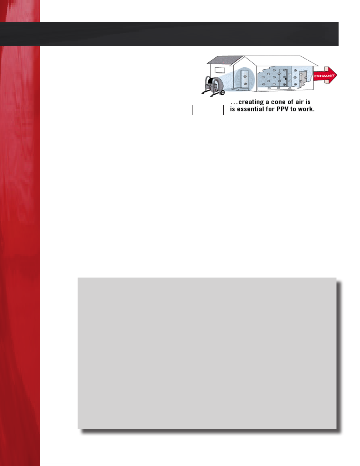
PPV and PPA rely on two principles, (1) a cone shaped air pattern, and (2) pressure. To
accomplish Positive Pressure Ventilation or Attack, the blower is placed on the outside
of the structure. It is positioned so that the cone shaped air pattern created by the blower
completely seals the entrance opening (Figure 1.2). When this seal is achieved, the air
pressure is increased equally at all points inside the structure. When an exhaust opening
is created, all of the interior air moves in one mass towards it. e result is fast, ecient
ventilation of the entire structure.
gure 1.2
NOTE:
e TEMPEST POWER BLOWER® is the most ecient tool for PPV and
PPA for two reasons. First, the exclusive Tempest tapered shroud design
creates a wide, stable, conical air pattern. Second, the seven blade air movement impeller used on all Tempest blowers is designed to create high pressure. ese two features make the TEMPEST POWER BLOWER® such a
powerful ventilation tool.
As with any new technique, Positive Pressure Ventilation requires training
and education in order to be implemented properly and safely. Tempest offers access to a complete line of training materials, which cover many applications for this powerful ventilation technique. For more information visit
www.tempest-edge.com, www.positivepressuretraining.com or contact us at
1.800.346.2143.
Page 8
Page 10

Operating Procedures
e information and instructions in this section should be routinely reviewed and followed before the actual operation of TEMPEST POWER BLOWER®.
Pre-Operation
VISUAL INSPECTION
Aer receiving and unpacking your blower, be sure to carefully inspect it for any damage that might have occurred during shipping. Should you nd any damage:
PLEASE NOTIFY TEMPEST TECHNOLOGY CORP.® IMMEDIATELY AT
1.800.346.2143
ENGINE OIL
Be sure to use only high quality detergent oil. Detergent oils keep the engine cleaner
and retards the formation of gum and varnish deposits.
RECOMMENDED OILS
HONDA engines: SF or SG SAE 10W-30 oil.
BRIGGS & STRATTON engines: SE, SF, SG SAE 30 oil.
ENGINE
BRIGGS 900 20 . oz. / 0.63 Quarts / 0.59 Liters
HONDA GX160 20 . oz. / 0.63 Quarts / 0.59 Liters
HONDA GX200 20 . oz. / 0.63 Quarts / 0.59 Liters
HONDA GX270 36 . oz. / 1.13 Quarts / 1.07 Liters
CAPACITY
FILLING THE CRANKCASE
Place blower on a level surface and make sure that the engine is level. Remove the oil
ll plug or dipstick. POUR OIL SLOWLY into the crankcase. Replace oil ll plug or
dipstick and tighten securely. Refer to the engine manufacturers Owners Manual for
additional information regarding specic oil requirements.
CAUTION: DO NOT OVERFILL THE ENGINE. EXCESS OIL VAPOR
CAN BE EJECTED FROM THE ENGINE BREATHER WHILE RUNNING IN FULL TILT POSITION.
Page 9
Page 11

Operating Procedures Continued
FUEL
Always use clean, fresh, lead-free gasoline with an octane rating of 86 or higher. DO
NOT USE leaded gasolines. Refer to the engine manufacturers Owners Manual for acceptable substitute gasolines.
CAUTION: PRECAUTIONS MUST BE FOLLOWED WHENEVER
REFUELING GASOLINE ENGINES. PLEASE FOLLOW THE LISTED
GUIDELINES.
- DO NOT FILL THE FUEL TANK INDOORS.
- DO NOT FILL THE FUEL TANK WHILE THE ENGINE IS RUNNING
OR HOT.
- DO NOT SMOKE DURING REFUELING.
- DO NOT FILL THE FUEL TANK COMPLETELY. FILL THE TANK TO
BOTTOM OF FILTER TO PROVIDE SPACE FOR FUEL EXPAN SION.
- WIPE ANY SPILLAGE FROM ENGINE AND COMPONENTS BE FORE STARTING THE ENGINE.
ENGINE
BRIGGS 900 96 . oz. / 3 Quarts / 2.84 Liters
HONDA GX160 106 . oz. / 3.31 Quarts / 3.13 Liters
HONDA GX200 106 . oz. / 3.31 Quarts / 3.13 Liters
HONDA GX270 179 . oz. / 5.59 Quarts / 5.29 Liters
CAPACITY
Page 10
Page 12

Operating Procedures Continued
Operation
SET-UP, STARTING AND STOPPING
Assuming the previous Pre-Operation instructions have been followed the blower is
now ready to run. Please review the engine manufacturers Owners Manual regarding
starting and stopping as well as the instructions in this section before actually starting
the blower.
CAUTION: DO NOT MOVE THE BLOWER WHILE IT IS IN OPERATION. SEVERE PERSONAL INJURY IS POSSIBLE AS WELL AS DAMAGE
TO THE BLOWER.
ALWAYS SHUT-DOWN THE BLOWER PRIOR TO MOVING!
SET-UP
Position the blower in the desired location, making sure it is placed on a at, hard and
debris free surface.
STARTING
1. Set the stop switch/ignition switch to the “ON” position.
2. Set the fuel valve/fuel shuto switch in the “ON” position.
3. Set (if equipped) the choke lever to the “CLOSED” or “STARTING”
position.
4. Set the throttle lever to the 1/2 open position.
5. Grasp the starter handle, take up the slack, and pull the rope briskly. Let the
rope return slowly. Repeat as necessary until the engine starts. Do not over pull the
rope.
6. If equipped with a choke, move the choke lever to the ½ position until the
engine runs smoothly and then to the open or o position.
7. Move the throttle to the desired speed. NOTE: Some blowers may tend to
“walk” if the throttle is not in the full position.
STOPPING
1. Move the throttle to the “IDLE” position.
2. Move throttle lever to the “OFF” position unless equipped with a stop
switch. If a stop switch is provided, turn the switch to the “OFF” position.
Page 11
Page 13
Maintenance Procedures
Proper maintenance is necessary to ensure that your ®Tempest Power Blower operates as
eciently and trouble-free as possible. By following the instructions in this section you
will be providing the maintenance needed to achieve this goal.
CAUTION: THE ENGINE MAY START SIMPLY BY ROTATING THE
BLADES. ALWAYS REMOVE THE SPARK PLUG WIRE PRIOR TO
WORKING ON THE BLADE SIDE OF THE MOTOR.
OIL CHANGE
Check the engine oil level before each use. e oil should be changed aer the rst three
(3) operating hours and every 50 hours thereaer. Oil changes should be performed
more frequently if the blower is being operated in dusty or dirty conditions. Changing
the oil is easier when the engine is still warm (not hot) from a recent running.
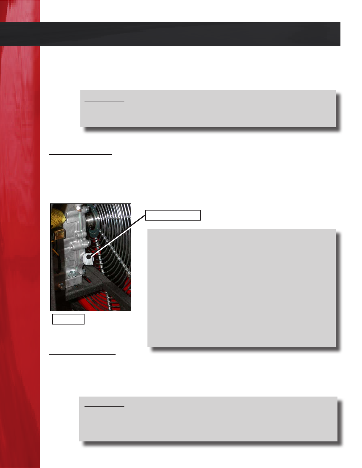
OIL FILLER CAP
PROCEDURES
1. Position the blower so the engine oil drain plug is
the lowest point on the engine.
2. Place a two quart or larger container under the oil
drain plug for the oil to drain into.
3. Remove the oil drain plug and drain the used oil.
4. Install the oil drain plug and tighten securely.
5. Remove the oil ller cap (gure 2.0) and rell with
gure 2.0
the recommended oil (refer to the Pre-Operation instructions in the Operations section) and check the oil
level.
AIR CLEANER
A dirty air cleaner will restrict airow to the carburetor. To prevent carburetor malfunction, service the air cleaner regularly. More frequent service may be necessary when the
blower is operated in extremely dusty conditions.
CAUTION:
REMOVED. RAPID ENGINE WEAR WILL RESULT FROM CONTAMINANTS, SUCH AS DUST AND DIRT BEING DRAWN THROUGH THE
CARBURETOR AND INTO THE ENGINE.
DO NOT RUN THE ENGINE WITH THE AIR CLEANER
Page 12
Page 14

Maintenance Procedures Continued
CLEANING AIR FILTER ELEMENTS
Foam Element:
1. Wash the element in a solution of household detergent and warm water, then rinse
thoroughly. Allow the element to dry completely.
2. Soak the element in clean engine oil, and squeeze out the excess oil. NOTE: the eng ine will smoke during initial start-up if too much oil is le in the foam element.
Paper Element:
1. To remove excess dirt, tap the element lightly several times on a hard surface or blow
compressed air through the lter from the inside out.
2. Do not try to brush the dirt o. Brushing will force dirt into the lter bers.
3. Replace the element if it becomes excessively dirty. You can order/purchase paper ele-
ments through Tempest or your local hardware/home improvement store.
COOLING SYSTEM
Frequently remove dirt and debris from the cooling ns, air intake screen, levers and
linkage. is will ensure adequate cooling and correct engine speed. Refer to the engine
manufacturer’s Owners Manual for additional cooling system information.
SPARK PLUG
A correctly ring spark plug is essential for the power blower to operate properly. Check
the engine spark plug yearly or every 100 hours by following the listed procedures.
1. Clean the area around the spark plug.
2. Remove and inspect the spark plug.
3. Replace the spark plug if the electrodes are pitted, burned, or the porcelain is cracked.
Check the electrode gap with a wire feeler gauge and set to the engine manufacturer’s
specications.
4. Make sure the spark plug washer is in good condition, and hand start the spark plug
to prevent cross threading.
5. Aer the spark plug is seated, tighten with a spark plug wrench to compress the wash er.
Page 13
Page 15

Maintenance Procedures Continued
CARBURETOR
All carburetors comply with federal & state regulations and are preset by the engine
manufacturer. Engine performance may dier at various altitudes and climates. If you
feel that the carburetor on your blower needs adjusting contact Tempest or your local
engine dealer.
EMISSION CONTROL SYSTEM
State regulations require that all manufacturers of gas powered engines furnish written
instructions describing the Operation and Maintenance of the emission control systems.
ese instructions vary depending on engine type. Please refer to your engine Operation and Maintenance Owners Manual under the heading “Emission Control Systems”
for specic information and instructions.
BLADE REMOVAL AND INSTALLATION
e following procedures cover removal and installation for the following blades.
- EB18 blade (260-075) requires a J 5/8 bushing
- DD18 blade (260-075) requires a J 1 bushing
- BD18 blade (260-075) requires a J 3/4 bushing
- EB21 blade (260-019) requires a J 5/8 bushing
- DD21 blade (260-017) requires a J 1 bushing
- BD21 blade (260-019) requires a J 3/4 bushing
- EB24 blade (260-021) requires a J 5/8 bushing
- DD24 blade (260-021) requires a J 1 bushing
- BD24 blade (260-026) requires a J 3/4 bushing
- BD27 blade (260-031) requires a J 1 bushing
CAUTION: THE ENGINE MAY START SIMPLY BY ROTATING THE
BLADES. ALWAYS REMOVE THE SPARK PLUG WIRE PRIOR TO
WORKING ON THE BLADE SIDE OF THE MOTOR.
Page 14
Page 16
Maintenance Procedures Continued
BLADE REMOVAL PROCEDURES
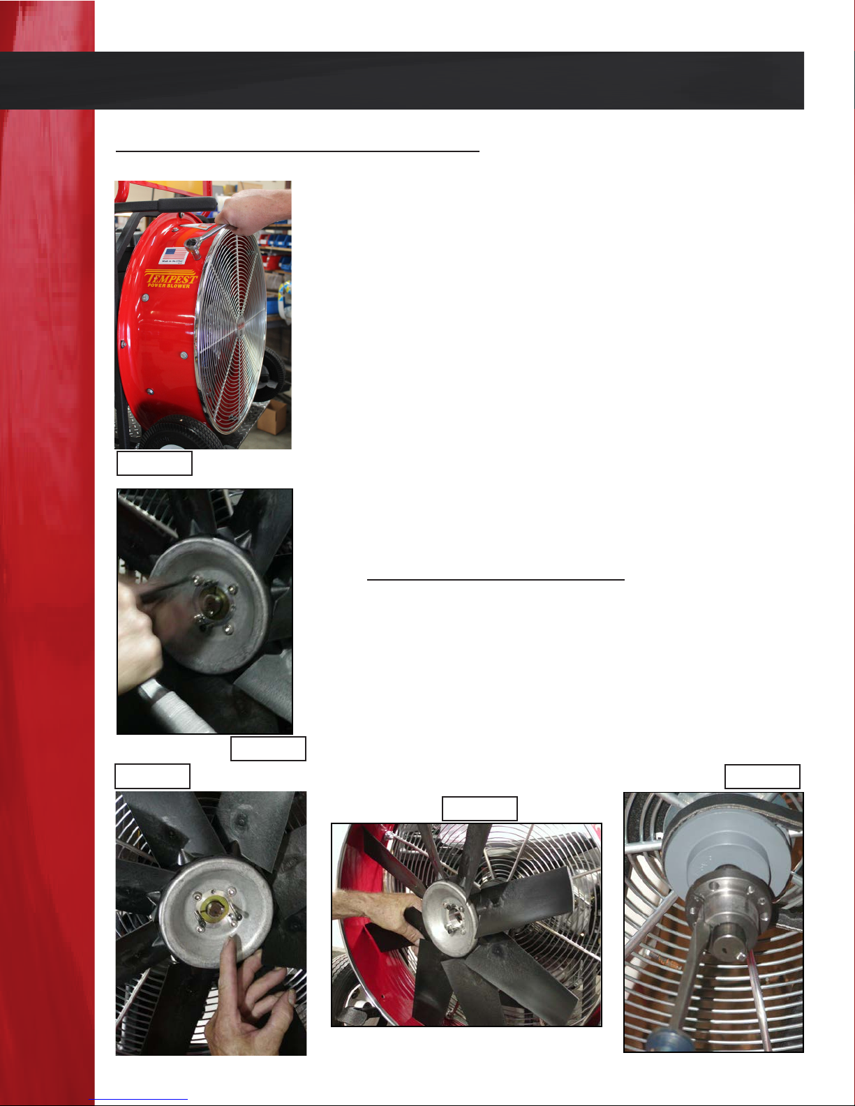
1. Remove the eight bolts holding the front grill in place
and remove the grill. (Figure 4.1)
2. Remove the three cap screws in the center of the fan
blade bushing with an 5/32 hex bit (Allen wrench
(Figure 4.2)
3. Insert the cap screws into the adjoining thread
holes in the bushing. (Figure 4.3) Turn the screws in a
clockwise manner. Tighten the cap screws progre sively with the wrench. Evenly tighten each cap screw
¼ to ½ a turn successively until the blade slides o of
the bushing. (Figure 4.4)
4. Insert a small screwdriver into the bushing slot (Fig-
Figure 4.1
ure 4.5) to release the bushing from the engine sha.
Be careful not to damage the end of the jacksha.
Remove the bushing and blade.
BLADE INSTALLATION
1. Put bushing on motor sha (Figure 4.5). Tighten the
allen screw on the bushing. Put blade on bushing
(Figure 4.4). Put lock washers on the three allen
screws and insert into drilled holes of blade. Turn
each screw and tighten evenly.
2. Reinstall front grill.
Figure 4.2
Figure 4.3
Figure 4.4
Figure 4.5
Page 15
Page 17
Maintenance Procedures Continued
BLADE REMOVAL AND INSTALLATION
e following procedures cover removal and installation for the following blades.
- DD16 blade (260-030) requires a G 1 bushing and a 3/16” X ¼” X 1” key.
- EB16 blade (260-069) requires a G 5/8 bushing and a 3/16” X 1 3/8” key.
BLADE REMOVAL PROCEDURES
1. Remove the eight bolts holding the front grill in place and remove the grill (Figure
4.1 on page 15).
2. Remove the three bolts from blade. Remove the two bolts from the bushing and hub.
Put the two bolts in the threaded part of the bushing and turn evenly until bushing
separates from hub.
BLADE INSTALLATION PROCEDURES FOR DD16
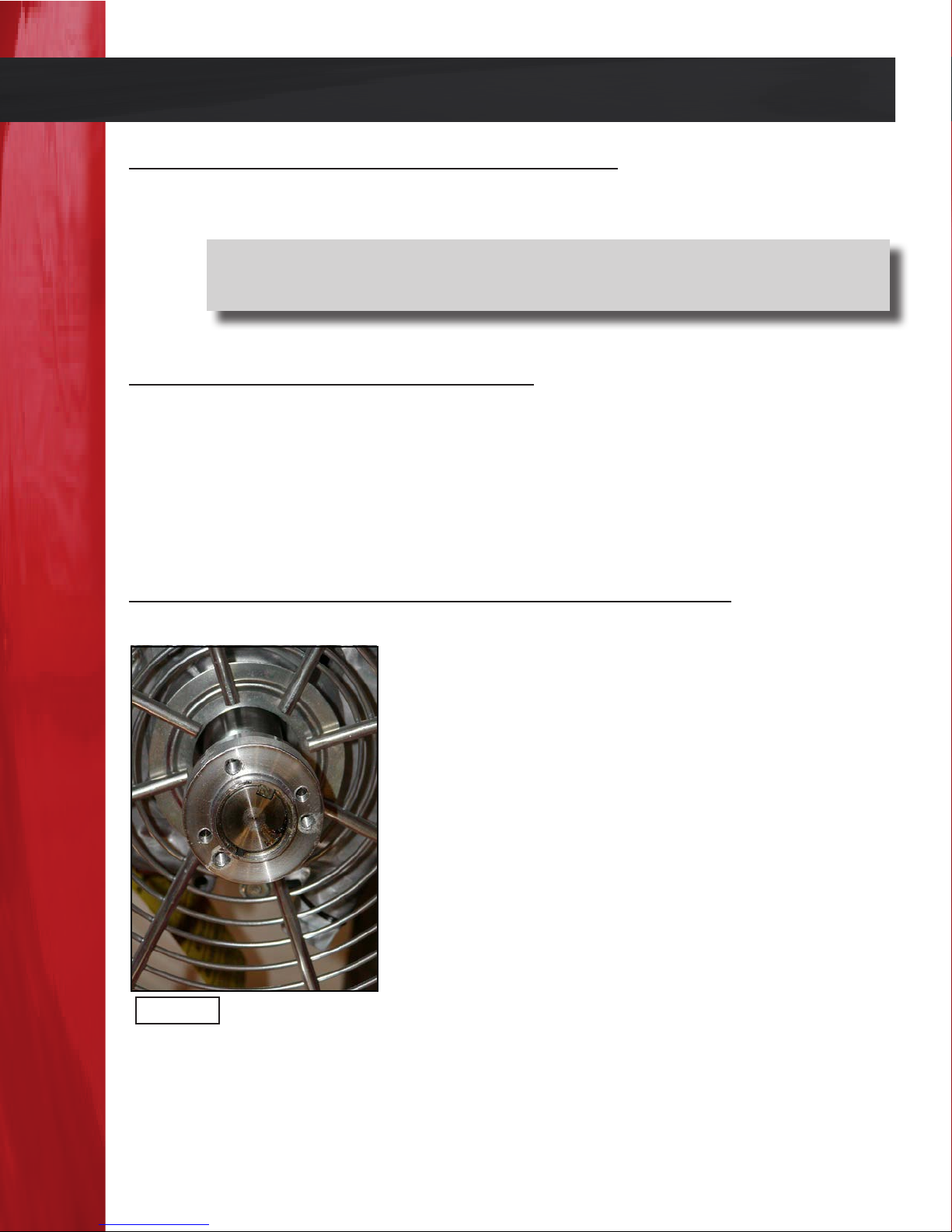
1. Make sure that the sha and keyway are clean and
smooth before installing the blade.
2. Insert the cap screws through the clearance holes in
the bushing and place loosely into the hub of the
blade. Do not press the bushing in.
3. Insert the cap screws, turning them just enough to
engage the threads in the tapped holes on the hub.
e bushing should be loose in the hub. Insert the
key into the keyway (Figure 4.6). Tighten two bolts
drawing the bushing and hub together.
Figure 4.6
Page 16
Page 18
Maintenance Procedures Continued
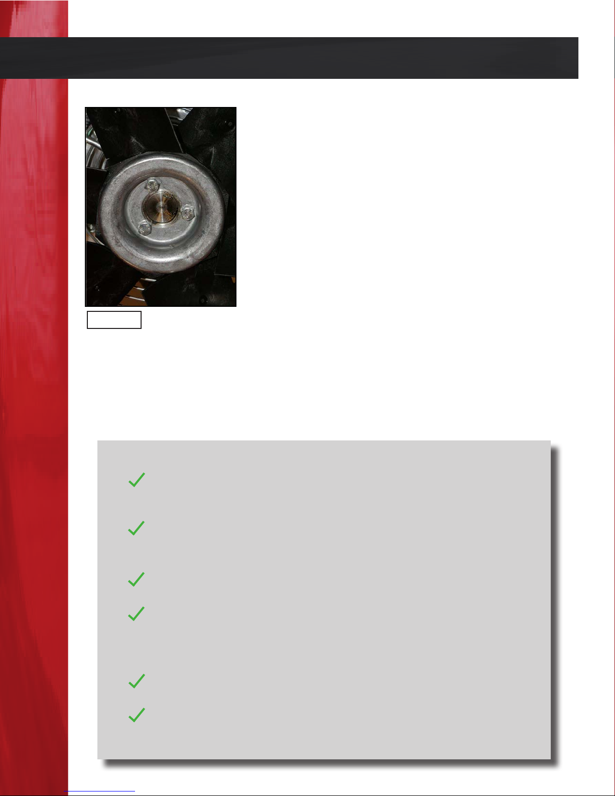
4. Slide the blade onto the bushing/hub assembly and
insert the three screws through the blade and turn
evenly but do not tighten. Make sure blade is in line
with hub then tighten screws (Figure 4.7). Locate
the blade and bushing so that the blade tips do not
hit the rear grill eyelets. On some models the blade
and bushing may be in beyond or out away from the
end of the sha up to ¼” but no further. is is nece ssary for proper blade clearance.
5. Tighten the cap screws progressively with a wrench.
Tighten each cap screw partial turns successively
until both are tight. Final tightening should be done
with torque wrench with the torque set at 7.5 .
Figure 4.7
6. Carefully turn the blade and check for clearance between the blade and shroud. Con rm that the blade is free to rotate without hitting other parts.
7. Reinstall the front grill and test the blower.
8. If you have any trouble removing or installing the blade on your blower, contact the
factory for assistance at 1.800.346.2143.
lbs. for each screw. Over tightening will cause the cap
screws to break or crack the blade. (Figure 4.7)
MAINTENANCE SCHEDULE
EVERY USE
CHECK ENGINE OIL
INSPECT BLOWER FOR DAMAGE AND FIX IF ANY
NEW BLOWER FIRST THREE HOURS
CHANGE ENGINE OIL
TENSION BELTS
EVERY MONTH OR 10 HOURS
CLEAN AIR FILTER
EVERY MONTH OR 25 HOURS
TENSION BELTS
INSPECT & CLEAN ENGINE HOUSING
TIGHTEN/REPLACE ANY LOOSE OR MISSING PARTS
EVERY MONTH OR 50 HOURS
CHANGE ENGINE OIL
EVERY MONTH OR 100 HOURS
REPLACE BELTS
INSPECT & CLEAN SPARK PLUG
Page 17
Page 19
Maintenance Procedures Continued
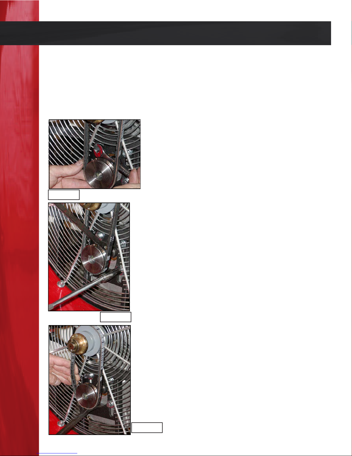
BELT ADJUSTMENT
e blower drive belt has been adjusted at the factory prior to delivery. However, the
belt should be inspected and checked aer the initial three (3) hours of operation as it
may require retightening due to belt stretch. It should be inspected aer every 25 hours
of operating time. Operating the blower with a loose belt will cause excessive wear and
reduce performance. Follow the procedures listed to properly adjust the drive belt.
1. Remove the eight bolts holding the front grill in place
and remove the grill. (Figure 4.1, Page 15)
2. Loosen the four front engine mount bolts. (Figure
5.0)
3. Use a lever to space or push the engine downward to
tighten the belt(s). (Figure 5.1) e belt(s) should be
snug and have very little play. DO NOT OVER-
Figure 5.0
TIGHTEN THE BELT(S).
4. Tighten the front engine mount bolts.
5. Re-install the front grill and test the blower.
BELT REPLACEMENT
1. Remove the eight bolts holding the front grill in place
and remove the grill. (Figure 4.1, Page 15)
2. Loosen the four front engine mount bolts. (Figure
5.0)
3. Pry the engine up to loosen and remove the belt(s).
(Figure 5.2)
4. Use a lever to pry or push the engine downward to
Figure 5.1
tighten the belt (s). e belt(s) should be snug and
have very little play. DO NOT OVERTIGHTEN THE
BELT (S).
5. Tighten the front engine mount bolts.
6. Re-install the front grill and test the blower.
Figure 5.2
Page 18
Page 20

Blower Troubleshooting
Many factors can contribute to or be the sole cause of problems for gas power blowers.
is section will identify some of these problems and provide solutions to correct them.
BLOWER FAILS TO START
• Check for fuel in the tank; make sure the fuel shut o valve is open.
• Check the fuel line to determine if the carburetor is getting fuel.
• Check the oil level, Honda engines are quipped with automatic oil alert systems. e
engine will not start if oil is low.
• Check the spark plug for a spark:
Remove the spark plug wire, clean any dirt from around the spark plug
1.
base and remove the plug.
2. Install the spark plug into the plug cap.
3. Ground the plug to the engine and pull the starter to see if a spark jumps
the gap. DO NOT HOLD THE SPARK PLUG IN YOUR HANDS; hold the
spark plug cap or wire.
4. If a spark is present, replace the spark plug and wire then try starting the
engine.
5. If the blower still does not start contact the factory or your local engine
dealer.
POOR BLOWER PERFORMANCE
• Check the air lter for cleanliness, clean if dirty.
• If the Blower is a belt-drive, make sure the belt(s) is/are tight.
• If the Blower is a Direct-Drive, make sure the blade is tight.
• If the fuel is more then two months old, replace the fuel with fresh fuel.
BLOWER MOVEMENT OR “WALKING”
• Adjust the rubber footpads on the back of the Blower by turning them either in or out.
Adjust the side that is walking. is will help to evenly distribute the weight of the
Blower to all four points of the frame.
• Most Blowers will walk if not running at full speed, make sure the Blower is running at
full speed.
• Make sure the Blower is sitting at and not on small rocks or other objects.
Page 19
Page 21

Notes:
Page 20
Page 22

Notes:
Page 21
Page 23

Notes:
Page 22
Page 24
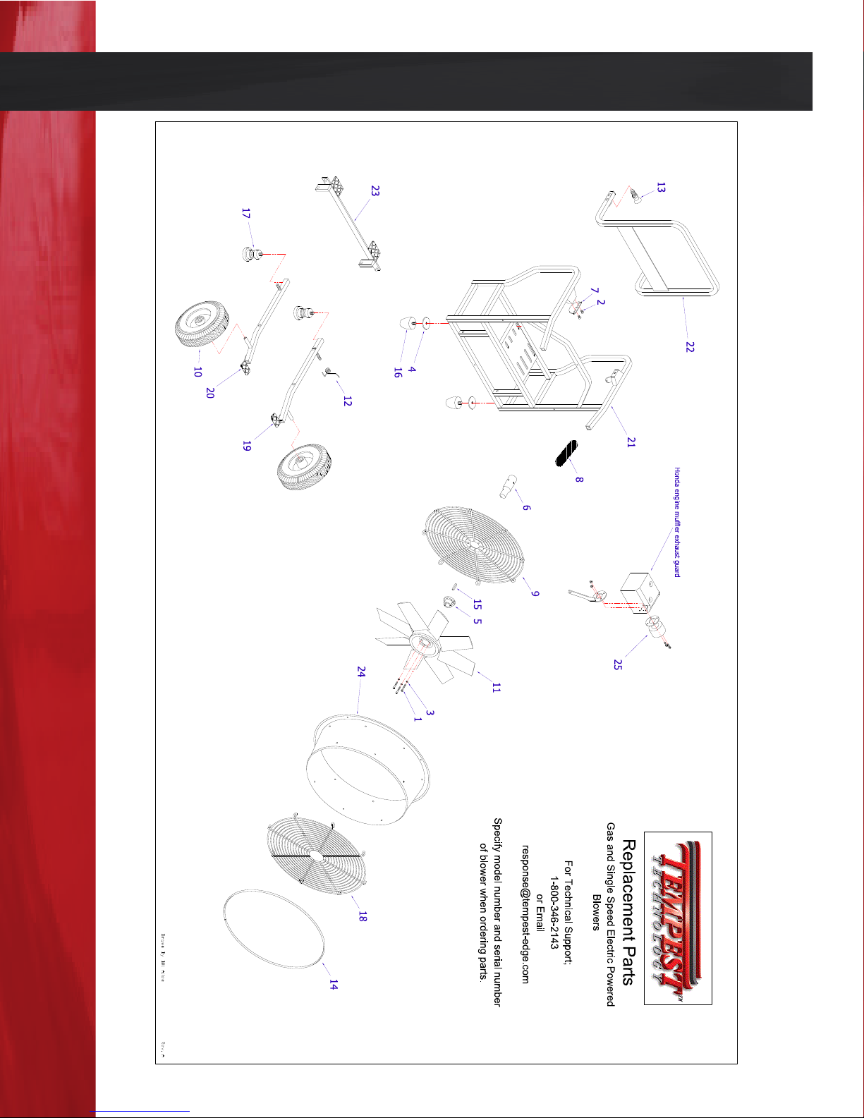
Direct-Drive Gasoline Power Blowers Exploded View
Page 23
Page 25
Direct-Drive Gasoline Power Blowers Parts List
NI = Not Ill lustrated REV A
* denotes item includes necessary hardware for installation
25* EXHAUST EXTENSION KIT FOR HONDA 725-047 725-047 725-039 725-039
NI HONDA ENGINE 350-004 350-004 350-016 350-016
NI BRIGGS ENGINE 350-024 350-024 350-024 350-024
19* LEG ASSEMBLY LEFT 2012 600-361K 600-350K 600-350K 600-350K
20* LEG ASSEMBLY RIGHT 2012 600-362K 600-351K 600-351K 600-351K
21* FRAME DD EB 600-669K 600-670K 600-672K 600-674K
22* HANDLE DD/ BD 2012 600-677K 600-678K 600-679K 600-680K
23* WIN STEP DD 2012 600-683K 600-684K 600-687K 600-689K
24* SHROUD, RED
705-100
705-105 705-110 705-115
18* FRONT GRILL 600-008 600-002 600-003 600-004
16 FOOT TAPERED 580-006 580-006 580-006 580-006
17 SPRING ASSEMBLY 600-001 600-001 600-001 600-001
13 SPRING PLUNGER W/HANDLE 300-170 300-170 300-170 300-170
14 TRIM FRONT 410-012 410-002 410-003 410-004
15 KEYSTOCK SQ STEEL (CUT 1.5") 460-064 460-064 460-064 460-064
12 SPRING TORSION 300-019 300-018 300-018 300-018
10 WHEEL FLAT FREE 240-008 240-012 240-012 240-012
11 BLADE ASSEMBLY (DD) (EB)
9 REAR GRILL 230-028 230-023 230-038 230-022
260-030 260-075
6* SHAFT 1" EXTENSION 4140 H.T. 170-004K 170-004K 170-004K 170-004K
7 HANDLE BRACKET 220-069 220-069 220-069 220-069
8 GRIP BASIC BLOWER HANDLE 220-248 220-248 220-248 220-248
3 WASHER #10 HIGH COLLAR LOCK NA 120-034 120-034 120-034
4 WASHER 3/8 X 2 FENDER HVY Z 120-037 120-037 120-037 120-037
5
TAPER LOCK BUSHING 160-040
160-019 160-019 160-019
Item # Description Part number Part number Part number Part number
1 BOLT 10-24 X 1 1/4 SOC P NA 100-059 100-059 100-059
2 1/4 X 1/2 FLAT SOC C/S ZINC 100-079 100-079 100-079 100-079
Replacement Parts For Direct Drive Gas Powered Blowers
May 2012 and Later
DD16 DD18 DD21 DD24
260-017 260-027
Page 24
Page 26
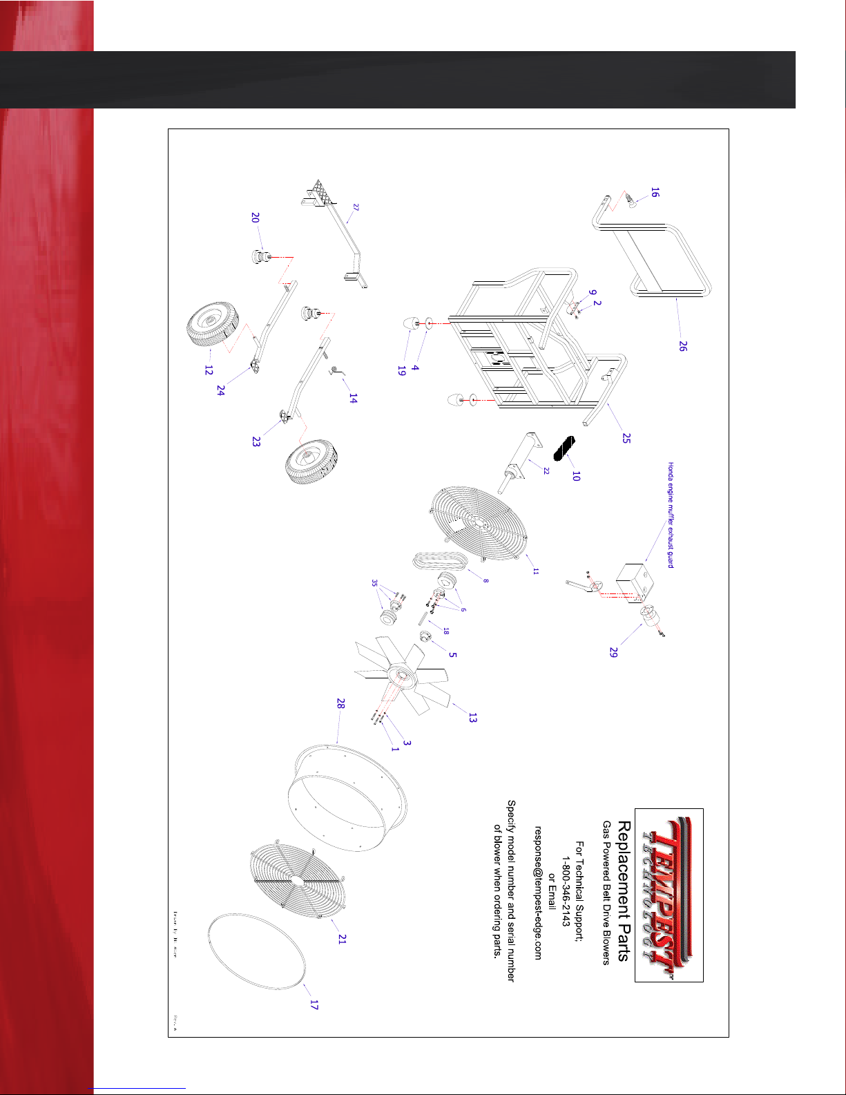
Belt-Drive Gasoline Power Blowers Exploded View
Page 25
Page 27
Belt-Drive Gasoline Power Blowers Parts List
NI = Not Ill lustrated REV A
* denotes item includes necessary hardware for installation
NI HONDA ENGINE 350-004 350-016 350-016 350-006 350-006
29* EXHAUST EXTENSION KIT FOR HONDA 725-047 725-039 725-039 725-093 725-093
28* SHROUD, RED 705-105 705-110 705-115 705-120 705-121
26* HANDLE DD/ BD 2012 600-678K 600-679K 600-680K 600-682K 600-682K
27* WIN STEP BD 2012 600-685K 600-688K 600-690K 600-691K 600-691K
24* LEG ASSEMBLY RIGHT 2012 600-351K 600-351K 600-351K 600-364K 600-293K
25* FRAME BD 600-671K 600-673K 600-675K 600-676K 600-676K
22* BEARING HOUSING ASSEMBLY 600-076K 600-076K 600-076K 600-229K 600-229K
23* LEG ASSEMBLY LEFT 2012 600-350K 600-350K 600-350K 600-363K 600-292K
21* FRONT GRILL 600-002 600-003 600-004 600-005 600-005
20 SPRING ASSEMBLY 600-001 600-001 600-001 600-001 600-001
19 FOOT TAPERED 580-006 580-006 580-006 580-006 580-006
18 KEYSTOCK SQ STEEL (CUT 3") 460-062 460-062 460-062 460-064 460-064
17 TRIM FRONT 410-002 410-003 410-004 410-005 410-005
16 SPRING PLUNGER W/HANDLE 300-170 300-170 300-170 300-170 300-170
NI SPRING TORSION RHW LEFT (BD 27 ONLY) NA NA NA 300-019 300-019
14 SPRING TORSION LHW RIGHT 300-018 300-018 300-018 300-018 300-018
13 BLADE ASSEMBLY
260-030 260-019
12 WHEEL FLAT FREE 240-012 240-012 240-012 240-012 240-008
11 REAR GRILL 230-023 230-038 230-022 230-026 230-026
10 GRIP BASIC BLOWER HANDLE 220-248 220-248 220-248 220-248
9 HANDLE BRACKET 220-069 220-069 220-069 220-069 220-069
8
DRIVE BELTS
108-014 180-011 180-001 180-002 180-002
7*
LOWER PULLEY KIT
160-030 600-371 600-371 600-372 600-372
6*
UPPER PULLEY KIT
160-030 600-072 600-065 600-066 600-066
5
TAPER LOCK BUSHING FOR FAN
160-018 160-018 160-018 160-018 160-018
4 WASHER 3/8 X 2 FENDER HVY Z 120-037 120-037 120-037 120-037 120-037
3 WASHER #10 HIGH COLLAR LOCK 120-034 120-034 120-034 120-034 120-034
2 1/4 X 1/2 FLAT SOC C/S ZINC 100-079 100-079 100-079 100-079 100-079
1 BOLT 10-24 X 1 1/4 SOC P 100-059 100-059 100-059 100-059 100-059
Item # Description Part number Part number Part number Part number Part number
BD 18 BD 21 BD 24 BD 27 BD 27 NY
Replacement Parts For Gas Powered Belt Drive Blowers
May 2012 and Later
260-026 260-031 260-031
220-247
Page 26
Page 28

“Committed to Fireghter Safety.”
Mission Statement
Tempest Technology Corporation’s mission is the promotion of the
use of air as a tool for eliminating hostile interior environments
encountered by reghters, rescue teams, industrial workers, and
industrial contractors worldwide.
is mission will be accomplished by identifying opportunities
where Positive Pressure Ventilation and other ventilation techniques
can be applied to make a work or emergency environment safer and
educating manufacturers, distributors and end users through live
demonstrations and professional training programs.
Tempest will continually improve and expand its existing product line
to meet the needs of customers in various domestic and international
markets. In order to fully utilize the strength of its resources and
worldwide distribution system, Tempest will develop strategic
partnerships, add complementary product lines and engage in private
labeling agreements with other manufacturers.
www.tempest-edge.com
4708 N. Blythe Avenue, Fresno, CA 93722 • Phone 559-277-
7577 Fax 559-277-7579 • [email protected]
 Loading...