

Page 1
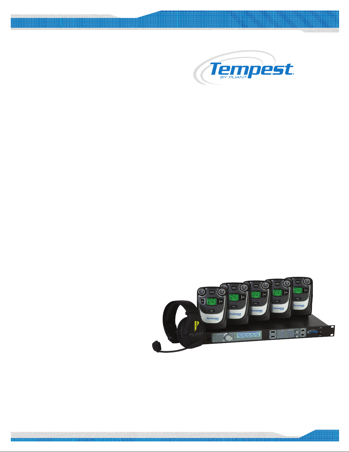
Tempest2400
4-Channel Quick Start Guide
What’s in each box:
BaseStation
• TMP-B424 BaseStation
• Power cord
• 2dBi Omni-directional Whip antenna (x2)
• 3.5mm to 3.5mm 3 conductor data pairing cable
» Used to pair a BaseStation to the BeltStation(s)
• USB-A to USB-B cable
» Used to update BaseStation rmware
• USB-A to Mini-USB
» Used to update BeltStation rmware
• BaseSync cable
» Used if you have more than one BaseStation
» Improves RF performance when using multiple systems
• CD with manual, T-Desk software
Quick Start Guide
5 Bay Battery Charger (optional)
• TMA-BCHRG-05A Battery Charger
• AC cable
Note: Charge ALL BeltStation batteries prior to set-up.
What else you may need:
• Headset, one for each user
» May be dynamic or electret microphone, with a 4-PIN XLR female
connector
• 3-PIN XLR cables to connect to external 2-Wire Intercom system
• RJ-45 cables to connect to external 4-Wire Intercom system
• RJ-45 cable to connect to PC for T-Desk LAN control
BeltStation
• TMP-R424 BeltStation
• Li-Poly rechargeable battery
• 5VDC wall charger with Mini-USB connector
Remote Transceiver (optional)
• TMP-RT24 Remote Transceiver
• RJ-45 to RJ-45 CAT-5 cable
• 2dBi Omni-directional Whip antenna (x2)
• Mounting plate and screws
Directional Antenna Kit (optional)
• TMA-ANTSYS-09C Directional antenna (x2)
• Mounting brackets (x2)
• Antenna mounting bar
• “C” clamp mount
• “RP-TNC” to “N” cables (x2)
1
Page 2
Quick Start Guide
Important things you need to know
Tempest2400 operates in the 2400 to 2483 MHz frequency
spectrum and should never be synced with Tempest900 models.
®
Tempest
default RF conguration. It is highly recommended that you
change your system from the default to ensure proper RF
performance, especially in the presence of other Tempest systems.
BaseStations and BeltStations are shipped with a
A BeltStation must be paired with a BaseStation for any
communication to take place. Pairing should be done AFTER the
default RF conguration is changed on the BaseStation.
Charge the BeltStation batteries prior to starting set-up.
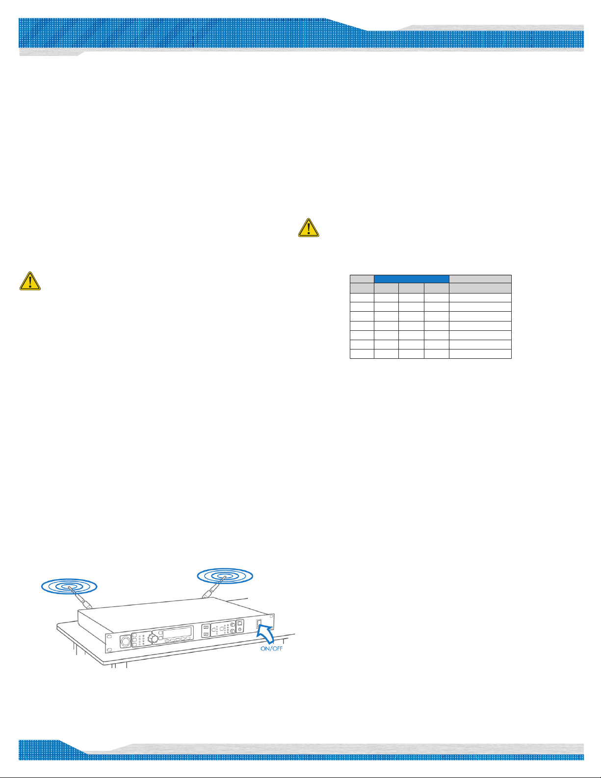
Select a location for the
1
BaseStation and/or Remote Transceiver
System range and performance may be greatly reduced if antennas are
blocked or obstructed.
• Always operate the system with both antennas attached, located
as high as possible and away from all obstructions (especially
metal).
• Never use the antennas on the back of the BaseStation when the
BaseStation is in a rack (greatly reduced range will be experienced).
• When using the omni-directional whip antennas, always locate
them as close as possible to the center of the coverage area.
• When using directional antennas, always aim them in the same
general direction.
• When remotely locating antennas, use only high quality 50 ohm,
low loss, RF cable (45 ft max, or approx 14m).
• Remote antenna location of up to 1500 ft (approx 457m) using
standard CAT-5 wiring may be achieved using the optional Tempest
Remote Transceiver.
» This connection cannot be through an active IP switch or router.
» Plug your Transceiver into the BaseStation prior to powering ON the
BaseStation.
Power ON the BaseStation
2
Selecting the RF band
3
• The rst time you power up the BaseStation, you will be
prompted to “select an authorized band for your location.”
• There are seven RF bands that use different parts of the 2.4GHz
spectrum.
• Scroll to an appropriate band for your location and press ENTER
to select.
• Press MENU to return to the operational screen.
Band 1 is appropriate for most, but not all locations worldwide
(US is band 1). Some countries require that you use a limited
portion of the 2.4GHz band. It is the user’s responsibility to
ensure you select a band that is permitted for use in your
location.
Band Start End Wide Avoid 802.11b/g
1 2400 2480 80 None
2 2400 2450 50 11
3 2423 2473 50 1
4 2431 2480 49 1,2
5 2400 2428 28 7,8,9,10,11
6 2423 2450 27 1,11
7 2453 2480 27 1,2,3,4,5,6,7
Changing the Default RF Conguration
4
From the front of the BaseStation, follow the steps below:
• Press MENU (Main Menu).
• Press 1 (BaseStation Settings).
• Scroll to 7 (Tech Menu) and press ENTER. A Tech Menu warning
message will appear—Press ENTER to proceed.
• Press ENTER or 1 (Radio Conguration).
• Press ENTER or 1 (Network Number) and select a network other
than zero, and press ENTER to save setting.
• If you have multiple BaseStations, ensure you select a different
Network Number for each BaseStation.
• Collocated BaseStations should be in the same Network Number
Group.
• Press MENU to return to previous menu; press 2 (Lockout Key)
and select a lockout key other than 255 and press ENTER to save
setting.
• Press MENU repeatedly until you get back to the operational
screen.
• Power the BaseStation OFF; wait 10 seconds and power the
BaseStation ON again.
MHz
• Connect the AC power cord to the BaseStation and to the AC
wall outlet.
• Turn the BaseStation on via the front panel ON/OFF switch.
2
Page 3
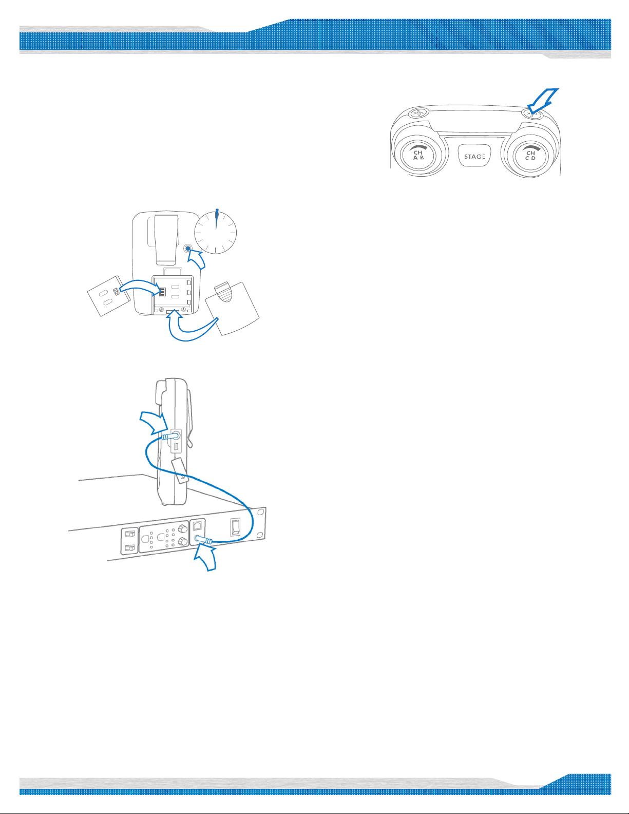
Power ON the BeltStation
5
• Slide the battery door off by pressing down and back.
• Install the battery or AA batteries (x3) and replace the battery
door.
• Press and hold the ON/OFF button for two seconds; the
BeltStation will vibrate as it powers up.
• Power the BeltStation OFF by pressing and holding the ON/OFF
button for four seconds.
2 sec
POWER ON
Pair BeltStations to the BaseStations
6
Quick Start Guide
Start Communicating
7
• Plug a headset into each BeltStation.
• To set Mic Gain, Press MENU and scroll down to Set Controls.
• Scroll to Mic Gain and Press ENTER.
• Set the Mic Gain for the headset you are using; speak loudly into the
microphone and adjust the setting so that the blue TALK LED ashes red at
your loudest point and then adjust down slightly. Press ENTER to save.
• Select the desired communication channel by pressing the A/B or C/D
channel selector.
• Adjust the headset listening volume by turning the A/B or C/D rotary
control.
• Press the TALK button to talk to others on the selected channel (the blue
ashing LED will remain lit when talk is enabled on that channel).*
• Conrm the desired talk channel and talk status by observing the
BeltStation LCD screen.
• Conrm the BaseStation is powered ON.
• Conrm the BeltStation is powered OFF.
• Connect the 3.5mm data pairing cable from the BaseStation to
the BeltStation.
• Power ON the BeltStation while observing the BeltStation LCD
screen; the BeltStation will vibrate and “Pairing Complete” will
appear momentarily on the LCD screen if pairing was successful.
• The BeltStation will return to the operational screen and log into
the BaseStation.
• The BeltStation will appear in the rst available slot on the LCD
screen.
• Repeat for each BeltStation.
Note: BeltStations are named to their default
setting name. They can be renamed.
Connecting to External 2-Wire Intercom Systems
8
• Select the correct intercom type on the front of the BaseStation.
» Intercom type select switch A&B controls intercom channels A and B;
C&D controls both intercom channels C and D.
» CLEAR-COM is used for Clear-Com and Clear-Com compatible 2-Wire
systems.
» RTS is used for RTS and RTS compatible systems.
» BAL is used for Telex AudioCom & AudioCom compatible systems.
• Connect 3-PIN XLR cables to the back of the BaseStation for the
appropriate channel.
• Press the left SEL button to select an intercom channel (A through D); press
the right SEL button twice to select 2-Wire operation.
• Use the IN and OUT rotary controls to set the IN (from 2-Wire to
BaseStation) and OUT (from BaseStation to 2-Wire) levels.
• Perform Auto Null from the BaseStation.*
Connecting to External 4-Wire Intercom Systems
9
• Connect RJ-45 cables to the back of the BaseStation for the appropriate
channel.
Note: The intercom type select switches do not apply
to 4-Wire operation.*
• Press the left SEL button twice to select an intercom channel (A
through D).
• Press the right SEL button to select 4-Wire operation.
• Use the IN and OUT rotary controls to set the IN (from 4-Wire to
BaseStation) and OUT (from BaseStation to 4-Wire) levels.
*Refer to the Tempest Owner’s Manual for detailed system information.
3
Page 4
Quick Start Guide
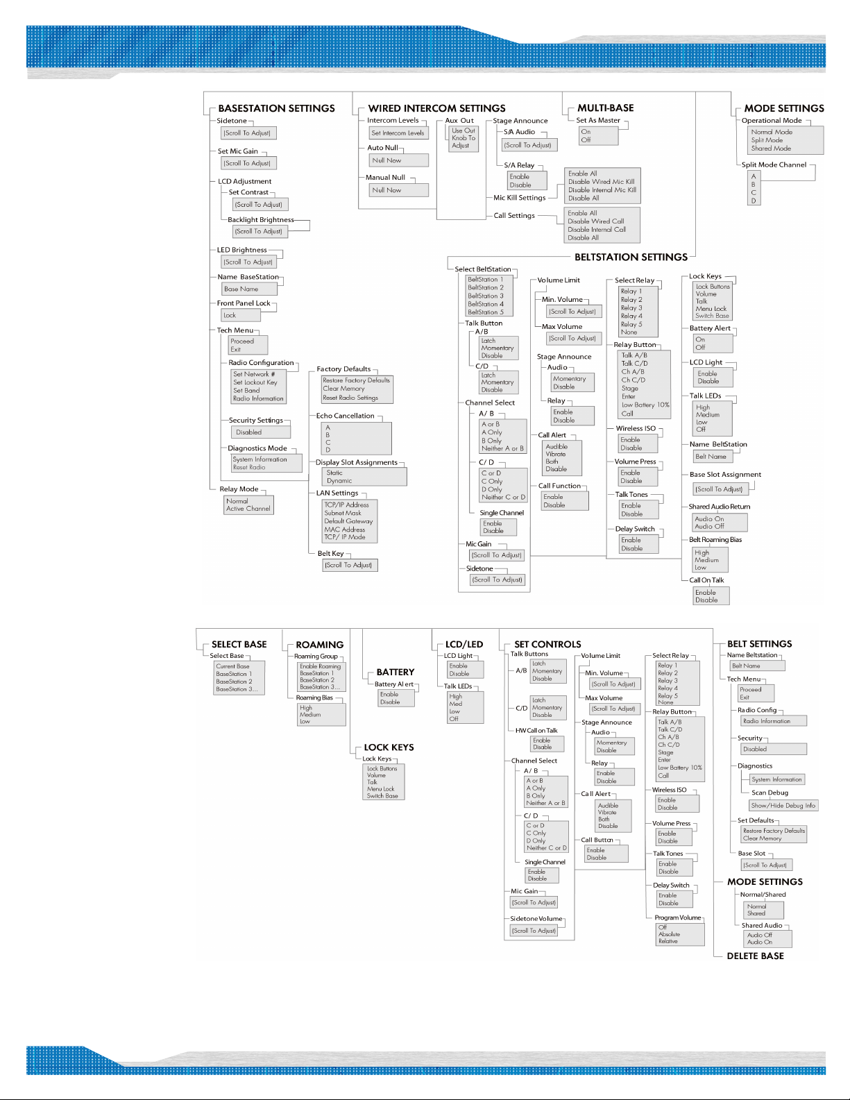
BaseStation Menu
BeltStation Menu
Pliant Technologies, LLC
®
Tempest
205 Technology Parkway
Auburn, AL 36830
www.plianttechnologies.com
Phone +1.334.321.1160
Toll-Free 1.844.475.4268 or 1.844.4PLIANT
Fax +1.334.321.1162
Copyright © 2016 Pliant Technologies, LLC. All rights reser ved. The Pliant™ word mark and the Pliant “P” logo
are trademarks of Pliant Technologies, LLC. The Tempest® word mark and Tempest® logos are trademarks of
CoachComm LLC. All other trademarks are property of their respec tive owners.
Tempest
TM24004CHQSG_D0000159_C
205 Technology Parkway
Auburn, Alabama 36830
4
© 2010 CoachComm LLC. All rights reserved.
Tempest® is a registered trademark of CoachComm, LLC.
®
Phone 334.321.2307
Fax 334.821.6861
www.tempestwireless.com
Tempest is manufactured by CoachComm, LLC and is distributed by Clear-Com, LLC.
®Clear-Com logo is a registered trademark of HM Electronics, Inc.
© Telex, AudioCom and RTS are registered trademarks of Telex Communications, Inc.
 Loading...