

Page 1
ISD 840K, 950K
Ducted Split System
Indoor Units
Installation &
Maintenance
GENERAL
These ISD indoor units are designed to be
coupled with their respective OSA outdoor
units. Units must be installed in accordance
with all national and local safety codes.
Combinations
One ISD 840K with one OSA 840RKTB
One ISD 950K with one OSA 950RKTB
Option
TZT-701 or SAT-2 Thermostat
Filters
INSTALLATION
Unpacking
The unit's supply air spigot has been
secured inside the unit for ease of shipping.
Remove the spigot and secure it in place
using the existing screws.
Positioning & Mounting
Provide sufficient clearance to the access
panels.
Mount on a suitable level platform using
vibration isolators. Access to fixing centres
beneath the return air spigot can be made
via the removeable bungs in the spigot's
base.
Condensate Drain
The unit has an internal sloping condensate
drain tray. The trap should have a vertical
height of at least 100 mm. The drain should
have a slope of at least 1 in 50 and must not
be piped to a level above the unit drain tray
(refer Fig.2).
For long condensate pipe runs, fit a vent
pipe near the drain trap. The top of the vent
pipe must be at least 100 mm above the ISD
unit's drain tray.
It is essential that the drainage system
for the evaporator is checked by pouring
water in the drain tray and seeing that it
discharges at the end of the drain and does
not overflow the drain tray.
INDOOR-OUTDOOR UNIT CONNECTIONS
Refer to the relevant OSA Outdoor Unit
'Installation & Maintenance' pamphlet for
piping instructions. For wiring connections,
refer to the Outdoor Unit wiring diagram.
REFRIGERATION PIPING
Pipe Connection Sizes & Type
Liquid : 16 mm OD (
5
/8") sweat
Suction : 35 mm OD (11/8") sweat
The ISD is shipped from the factory with
a pressurised holding charge of nitrogen.
Immediately before removing any brazed
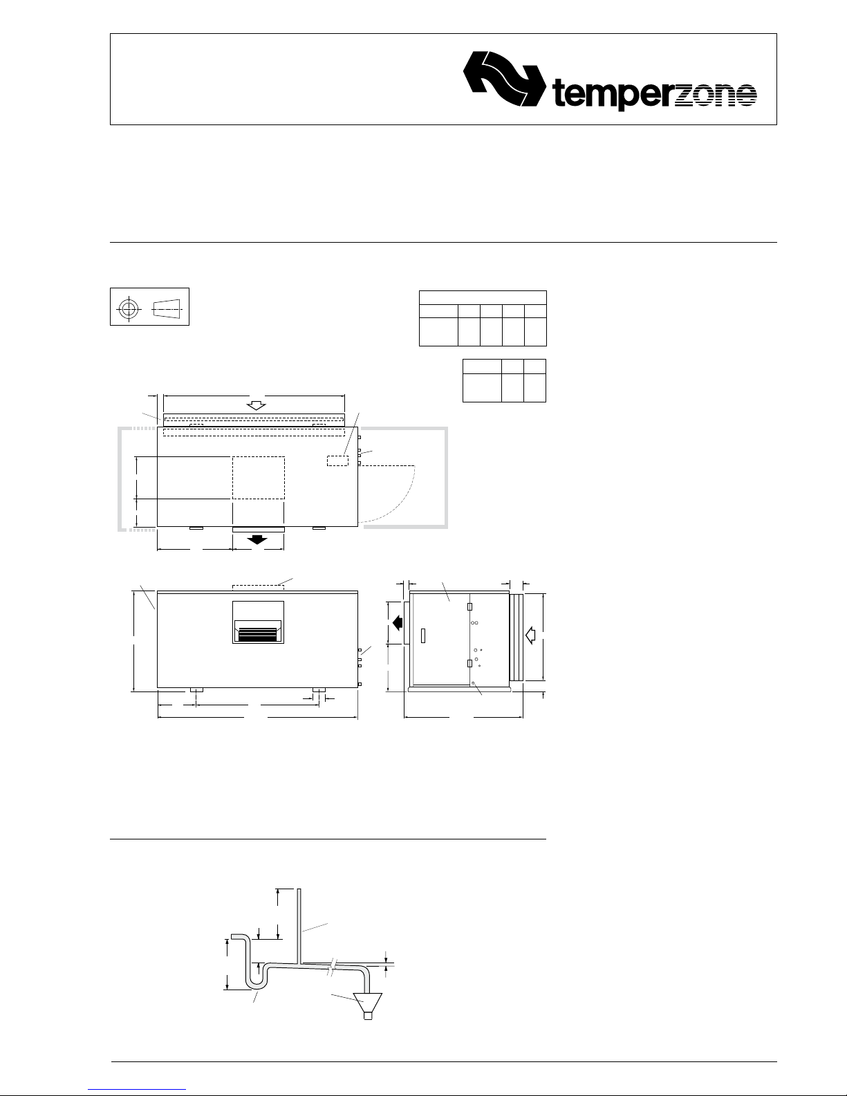
Fig.1 Dimensions (mm)
Not to Scale
Net
Weight
ISD 840K 372 kg
ISD 950K 383 kg
Fig. 2
NOTE
The manufacturer reserves the right to
change specifications at any time without
notice or obligation. Certified dimensions
available on request.
CORNER LOADS (kg)
MODEL W X Y Z
ISD840K 70 116 116 70
ISD950K 66 137 125 55
OPEN
DRAIN
MINIMUM
SLOPE
20 mm PER m
(1 IN 50)
100 mm
MINIMUM
200 mm
APPROX.
'U' TRAP
100 mm
APPROX.
VENT PIPE
FOR LONG
CONDENSATE
DRAIN RUNS
Condensate Drain
PROJECTION
2005
2220 OA
75
75
DRAIN 28 OD
150
60
1320 OA
W
X
Y
Z
REFRIG.
CONN’S
1000 MIN. CLEARANCE
1360
MOUNTING CENTRES
105
430
500 MIN. CLEARANCE
REFRIGERANT
CONNECTIONS
ELECTRICAL
BOX
ACCESS PANEL
FILTER ACCESS
EITHER SIDE
VERTICAL
DISCHARGE
MODEL
ELECTRICAL
ACCESS
PANEL
A
B
470
565830
305
470
535
MODEL A B
ISD840K 1070 955
ISD950K 1280 1165
Page 2
pipe connection's seal, reduce holding
charge to atmospheric pressure.
Warning: failure to do so may cause injury.
Refer to the Outdoor Unit 'Installation &
Maintenance' pamphlet for evacuation
procedure and piping requirements.
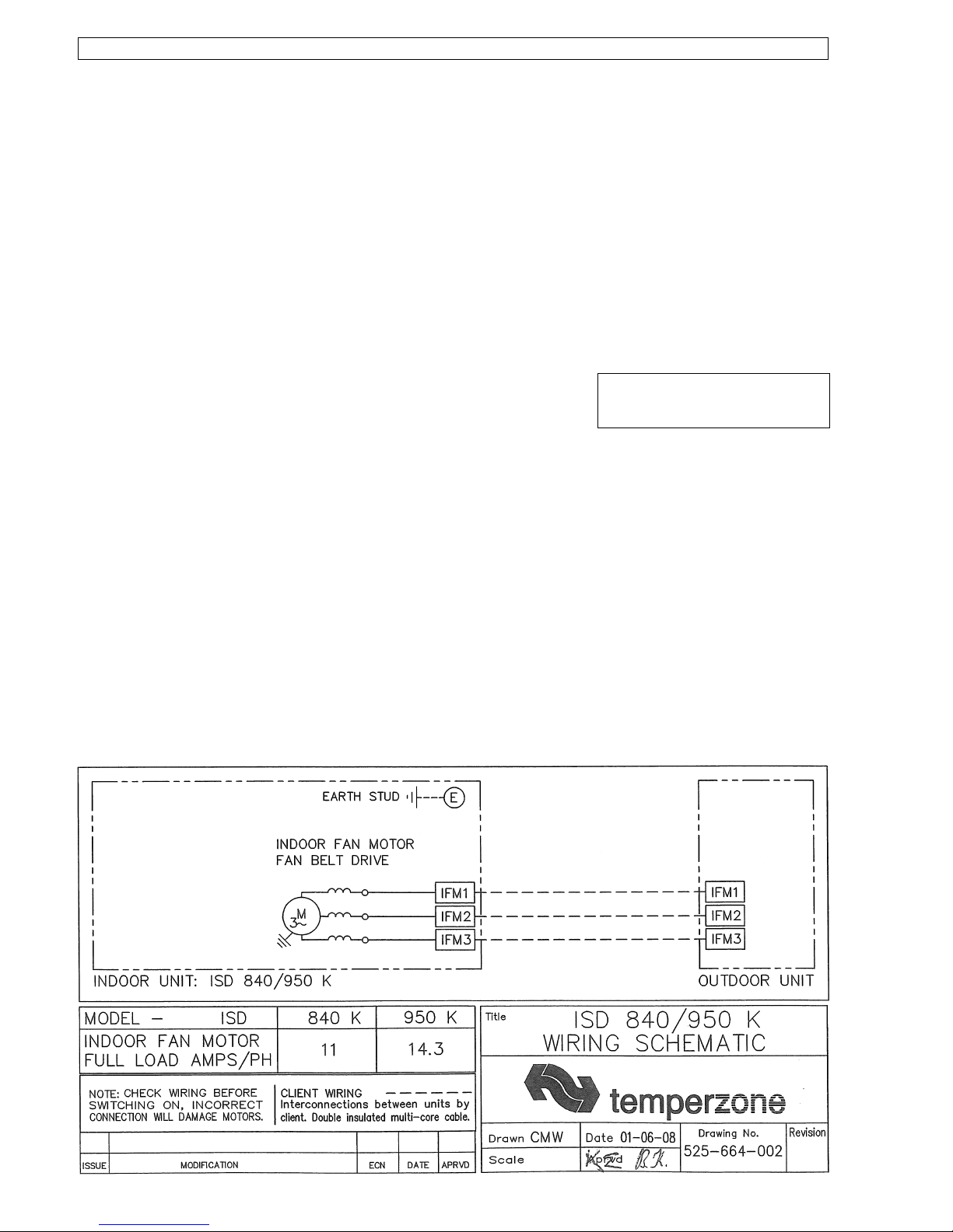
ELECTRICAL WIRING
The electrical supply required (via the
Outdoor Unit) is specified on the Outdoor
Unit's wiring diagram.
Electrical work must be carried out by a
qualified electrician in accordance with local
supply authority regulations and the wiring
diagram.
In a free blow or low resistance application,
beware of exceeding the fan motor's full
load amp limit (refer Outdoor Unit's wiring
diagram).
To make the indoor fan switch off during
de-ice cycle, refer to the Outdoor Unit wiring
diagram for the appropriate changes.
INDOOR FAN SPEED
The fan motor is fitted with a factory set
adjustable pitch pulley. One revolution of
adjustment is equal to 7% change in air
volume flow rate.
To change the fan speed loosen the motor
mounting plate hold down screws, loosen
the pulley grub screws and turn the pulley
flange the desired amount. The pulley
adjustment is locked by tightening the grub
screws in the keyways.
When setting air flows ensure that the
pulleys are in alignment. Tension the belt by
adjusting the motor mounting plate.
COMMISSIONING
Indoor Unit
1. Check that the thermostat is
correctly wired and set at the desired
temperature.
2. Check that any air filter (if fitted) is
clean.
3. Check that the fan runs freely without
vibration.
4. Check the airflow at each air outlet
(diffuser) and adjust if necessary.
5. Check condensate drain for free
drainage.
6. Run the unit in cooling mode and
heating mode.
MAINTENANCE
Weekly For First Four Weeks
1. Check air filter (if fitted); vacuum clean as
necessary.
2. Check condensate drain for free
drainage.
Monthly
Check air filter (if fitted); vacuum clean as
necessary.
Six Monthly
1. Check condensate drain for free
drainage.
2. Check heat exchanger coil; vacuum or
brush clean as necessary.
3. Check the tightness of the fan, motor
mountings, pullley and belt tension.
4. Check that fan motor is free running.
5. Check tightness of electrical connections.
6. Check air supply at diffuser outlets.
WARNING
This unit is designed for use ONLY with the
refrigerant HFC -410A (R410A). The use
of other refrigerants is NOT authorised or
approved by the manufacturer and may
cause operational problems such as poor
performance and efficiency, loss of capacity,
degradation of materials and refrigerant
leaks.
The use of flammable or explosive
materials as a refrigerant creates the
additional risks of fire and explosion
which may result in property damage,
personal injury or death.
NOTE
The manufacturer reserves the right to
change specifications at any time without
notice or obligation. Certified dimensions
available on request.
This pamphlet replaces the previous
issue no. 3753 dated 08/13.
Minor dimension correction.
12/13 Pamphlet No. 3753
© temperzone limited 2013
 Loading...