

Page 1
ISD 220Q, 265Q
Ducted Split System
Indoor Units
Installation &
Maintenance
GENERAL
The ISD 220Q indoor units are designed to
be coupled with the OSA 220 outdoor units.
The ISD 265Q indoor units are designed to
be coupled with the OSA 265 outdoor units.
Units must be installed in accordance with
all national and local safety codes.
Options
1. Filter Box.
2. Spring Mounting Kit
3. Electric Heater Box.
FILTER BOX (Option)
The Filter Box is installed by unscrewing
the return air spigot and replacing it with
the Filter Box's filter-integrated spigot. The
filter may be accessed from either side of
this spigot. This new spigot has a depth of
135 mm, instead of 60 mm.
ELECTRIC HEATER BOX (Option)
The Electric Heater Box is installed by
unscrewing the supply air spigot and
replacing it with the Electric Heater Box's
element-integrated spigot. This new spigot
has a depth of 195 mm, instead of 60 mm.
A separate page of installation instructions
is supplied with the Kit.
UNPACKING UNITS
In an area adjacent to the installation site
remove from the ISD unit from its carton
and examine it carefully for any damage
which may have occurred in transit. Record
any damage on the carrier's delivery
documents and refer the matter
immediately to the manufacturer's nearest
Sales Office.
INSTALLATION
Positioning & Mounting
Provide 500 mm minimum clearance to the
electrical panel. If the filter box option is to
be used, allow adequate clearance for the
two half length filters to be withdrawn from
either side of the unit.
If the Electric Heat Kit option is to be used,
allow adequate clearance for servicing.
If low noise is a critical factor in the
installation, refer to Figure 6 for noise
isolation recommendations.
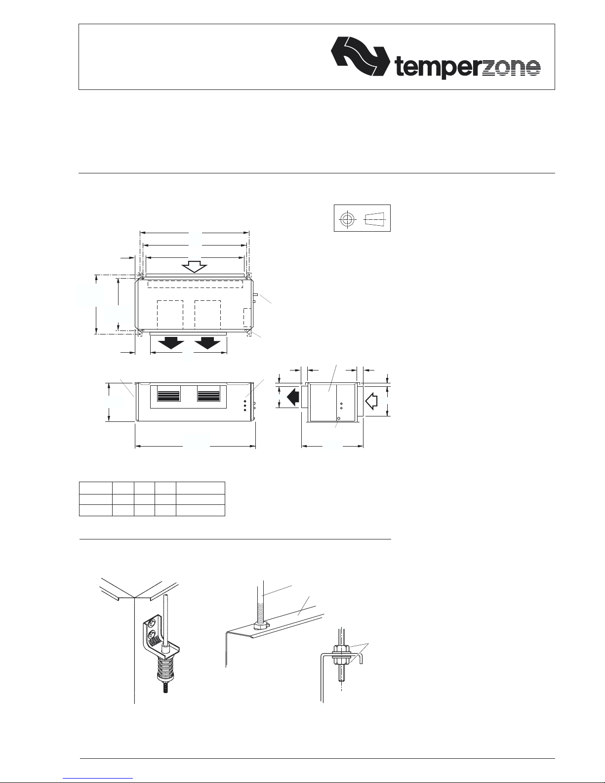
It is recommended that the unit be mounted
using the spring mounting system, supplied
as an optional extra (Fig.2). This system
minimises transfer of vibration into the
building structure.
If a more rigid installation can be tolerated,
then suspend the unit from four threaded
rods (not supplied) and use locknuts (not
supplied), as shown in Figure 3.
Fig. 1 Dimensions (mm)
Not to Scale
PROJECTION
NOTE
The manufacturer reserves the right to change
specifications at any time without notice or
obligation. Certified dimensions available on
request.
Fig. 2 Spring Mounting Fig. 3 Solid Mounting
TIGHTEN
LOCKNUTS
FOR
STRENGTH
MOUNTING FLANGE
MOUNTING ROD
RECOMMENDED
MOUNTING
SYSTEM
(OPTIONAL
EXTRA)
1185
ELECTRICAL
ACCESS PANEL
REFRIGERANT
CONNECTIONS
80
230
15
B
630 OA
MOUNTING
SLOTS 20 x 9
530
HANGING
CENTRES
865
595
OPTIONAL
SPRING MTG
CENTRES
165
ELECTRICAL
CONDUIT HOLES
6060
1365
OVERALL
1240
HANGING CENTRES
DRAIN 19 OD
FAN ACCESS VIA
REMOVEABLE BASE
& DRAIN TRAY
ACCESS
PANEL
1285
SPRING MTG CTRS
A
OVERALL
C
ISD 220Q, 265Q
B
15
85
A
425
555
C
350
500
MODEL
ISD 220Q
ISD 265Q
Net Weight
74 kg
93 kg
Page 2
The unit must be installed with the drain
tray tilted about 10 mm along its length so
that the drain connection is at the lowest
point.
When finally positioned, tighten the lock
nuts on the mounting rods from above and
below the mounting flange to give a firm
installation (see Fig. 3).
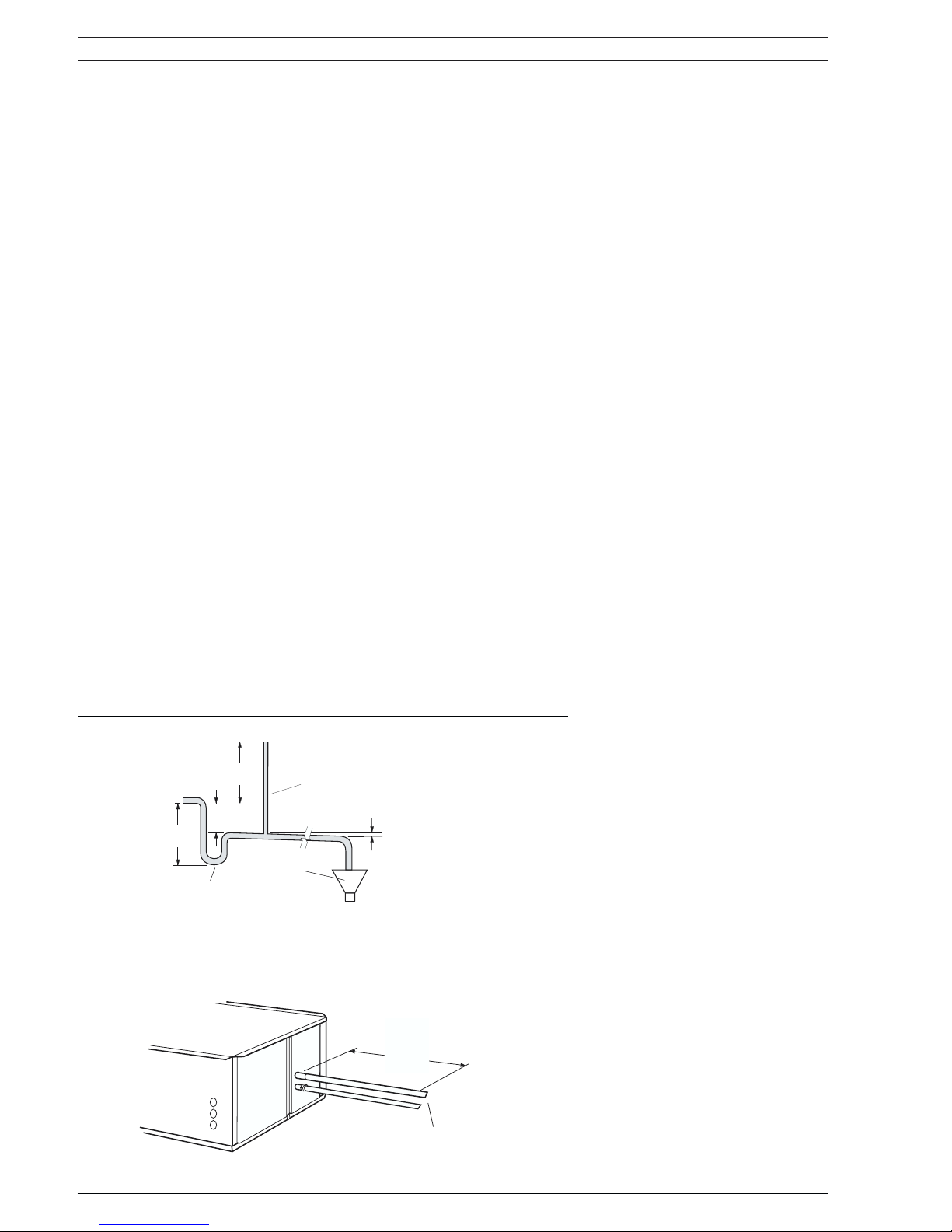
Condensate Drain
The condensate drain should be trapped
outside the unit cabinet. The trap should
have a vertical height of at least 50 mm.
The drain should have a slope of at least
1 in 50 and must not be piped to a level
above the unit drain tray. (Refer Fig.4).
For long condensate pipe runs, fit a vent
pipe near the drain trap. The top of the vent
pipe must be at least 100 mm above the
ISD unit's drain tray.
It is essential that the drainage system for
the evaporator is checked by pouring water
in the drain tray and seeing that it
discharges at the end of the drain and does
not overflow the drain tray.
INDOOR-OUTDOOR UNIT
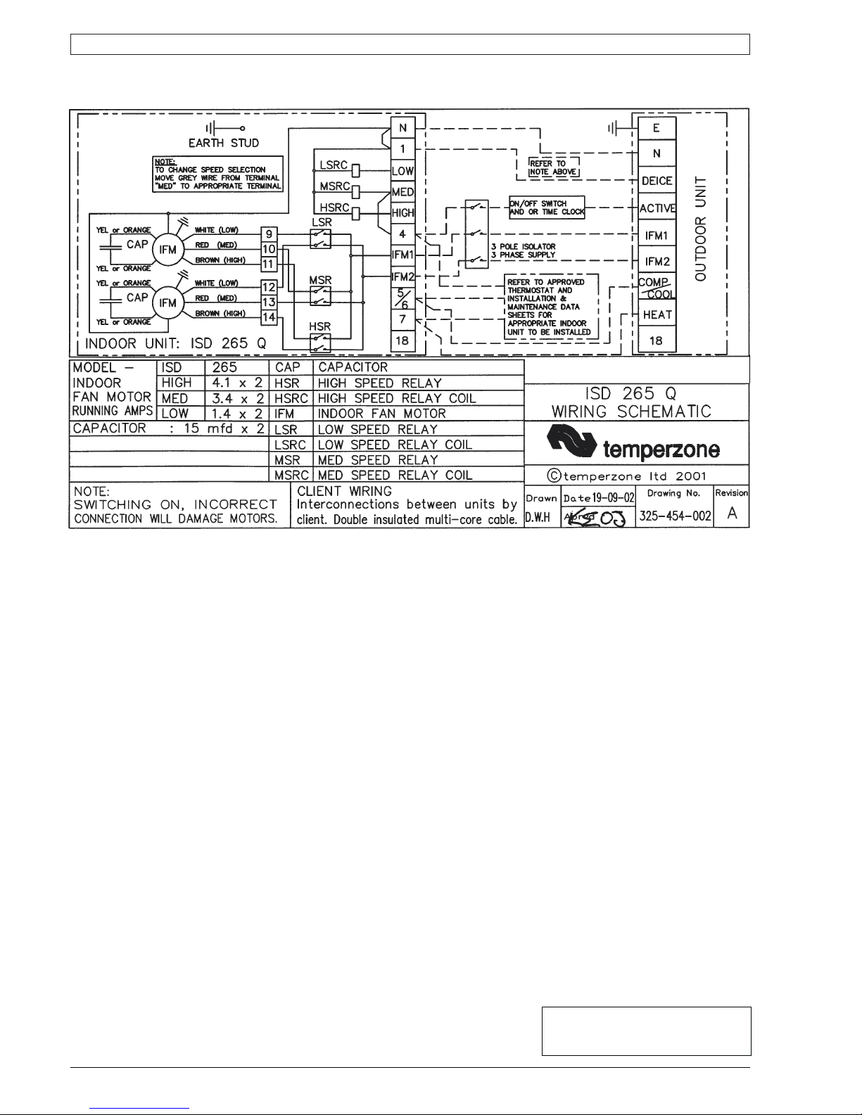
CONNECTIONS
Refer to the relevant OSA Outdoor Unit
'Installation & Maintenance' pamphlet for
piping instructions. For wiring connections,
refer to the Outdoor Unit wiring diagram in
conjunction with the ISD wiring diagram on
this pamphlet.
REFRIGERATION PIPING
Pipe Connection Sizes & Type
Liquid : 13 mm OD (1/2") flare
Suction : 28 mm OD (11/8") sweat
The ISD is shipped from the factory with a
pressurised holding charge of nitrogen.
STRAIGHT
PIPEWORK
400 mm
MINIMUM
SUPPORT PIPEWORK
AT THIS END
Pipework Connection
Fig. 5
Immediately before removing any brazed
pipe connection's seal, reduce holding
charge to atmospheric pressure by
loosening flare nut pipe connection.
Warning: failure to do so may cause injury.
Allow a minimum of 400 mm straight
pipework directly out from where the pipes
exit the unit (Fig.5). This is will permit
easier access for future servicing.
Refer to the Outdoor Unit 'Installation &
Maintenance' pamphlet for evacuation
procedure and piping requirements.
ELECTRICAL WIRING
The electrical supply required (via the
Outdoor Unit) is specified on the Outdoor
Unit's wiring diagram.
Electrical work must be carried out by a
qualified electrician in accordance with
local supply authority regulations and the
wiring diagram.
In a free blow or low resistance application,
beware of exceeding the fan motor's full
load amp limit (refer Outdoor Unit's wiring
diagram).
It is recommended electricians run two
spare wires between Outdoor Unit and
Indoor Unit in case one or both of the
following options becomes a requirement.
Note: Leave the wires unconnected until
required.
Option 1. Indoor Fan Off During De-Ice
(Reverse Cycle Systems only)
Connect one of the spare wires mentioned
above and remove the loop wire from
terminal 'N' to terminal '1'.
Option 2. Electric Boost Heat.
Connect one of the spare wires mentioned
above from Indoor Unit terminal '18' to
Outdoor Unit terminal '18'.
INDOOR FAN SPEED
The fan speed can be set to LOW, MED, or
HIGH - whichever best suits the
application.
If the air returning to the indoor unit is
regularly expected to be above 50%RH,
then the coil face velocity should be limited
to be 2.5 m/s or less (refer Air Handling
graph in Technical Data pamphlet).
High humidity levels can occur in tropical or
subtropical conditions, and/or when heavily
moisture laden fresh air is introduced.
Select a fan speed that avoids water carryover problems.
THERMOSTATS
For options, refer to the temperzone
pamphlet 'ISD 73Q-300Q - Approved
Thermostats' Data Sheet. A dedicated
neutral line is required where electronic or
anticipator thermostats are used when you
choose to have indoor fan off in de-ice.
COOLING OPERATION
An Outdoor Unit HP Fan Speed Controller
(4 amp), available from temperzone, is
recommended where indoor cooling is
required at ambient conditions below 20°C.
COMMISSIONING
Indoor Unit
1. Check that the thermostat is correctly
wired and set at the desired
temperature.
2. Check that the air filter (if fitted) is
clean.
3. Check that the fan runs freely without
vibration.
4. Check condensate drain for free
drainage.
5. Run the unit in cooling and heating
modes.
MAINTENANCE
Weekly For First Four Weeks
1. Check air filter (if fitted); vacuum clean
as necessary.
2. Check condensate drain for free
drainage.
Monthly
Check air filter (if fitted); vacuum clean as
necessary.
Six Monthly
1. Check condensate drain for free
drainage.
2. Check heat exchanger coil; vacuum or
brush clean as necessary.
3. Check the tightness of the fan.
4. Check that fan motor is free running.
5. Check tightness of electrical
connections.
6. Check air supply at diffuser outlets.
WARNING
This unit is designed for use ONLY with the
refrigerant HCFC-22. The use of other
refrigerants is NOT authorised or approved
by the manufacturer and may cause
operational problems such as poor
performance and efficiency, loss of
capacity, degradation of materials and
refrigerant leaks.
The use of flammable or explosive
materials as a refrigerant creates the
additional risks of fire and explosion
which may result in property damage,
personal injury or death.
Condensate Drain
Fig. 4
OPEN
DRAIN
MINIMUM
SLOPE
20 mm PER m
(1 IN 50)
50 mm
MINIMUM
100 mm
APPROX.
'U' TRAP
100 mm
APPROX.
VENT PIPE
FOR LONG
CONDENSATE
DRAIN RUNS
Page 3
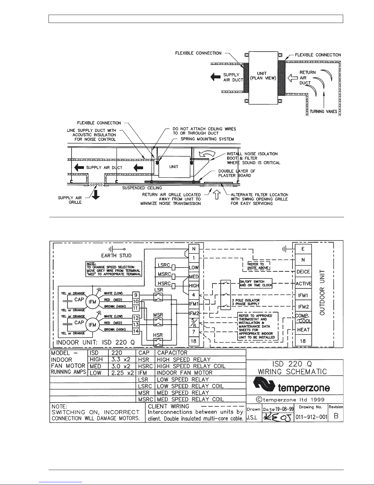
Recommendations for Noise Isolation
- particularly for high static installations:
1. Avoid installing units, with non-ducted return air, directly above
spaces where noise is critical.
2. Use flexible connections between unit and rigid ducting.
3. Use generously sized acoustically lined ducts.
4. If generous duct size is not possible, use turning vanes on bends
to reduce air turbulence (regenerated noise).
5. Use 90° bends in ducting to significantly assist in noise reduction.
Fig. 6 Application Considerations
Wiring
NOTE
The manufacturer reserves the right to
change specifications at any time without
notice or obligation. Certified dimensions
available on request.
ISD 220Q
Page 4
06/03 Pamphlet No. 2230
© temperzone limited 2003
This pamphlet replaces the previous
issue no. 2165 dated 11/02.
ISD 220Q wgt, wiring revisions B & A.
Wiring
ISD 265Q
 Loading...