

Page 1

HWP 35, 47, 58
440
HANGING
CENTRES
SLOPING
DRAIN TRAY
355
OVERALL
472
OPTIONAL
SPRING MTG
CENTRES
F
OPTIONAL
SPRING MOUNTING CENTRES
C
55
75
D
COIL
150
OPTIONAL
R/A FILTER BOX WITH
FILTER ACCESS
EACH SIDE
OPTIONAL
FILTER BOX
G
(HEIGHT = 257)
IN
OUT
(WATER)
55
685
OVERALL
40
PROJECTION
Nomenclature
Ducted Water Cooled R410A
Packaged Air Conditioner
Fig. 1 Nomenclature
e.g.
H
Series Size Type
H - Hideaway
W - Water Sourced
P - Packaged
Fig. 2 Dimensions (mm)
HANGING CENTRES
20 X 9 SLOTS
257
DRAIN 19 OD
MODEL A B C D E F G
HWP 35 845 477 40 105 825 900 480
HWP 47 845 477 40 105 825 900 480
HWP 58 1110 742 45 90 1090 1165 745
OVERALL
B
SUPPLY AIR SPIGOT
E
A
Divide by 10
to get approx.
nominal
Capacity in
kilowatts
ELECTRICAL
BOX
CW P 3 5 K
C - Cooling only
CE - Cooling only with electric heat
R - Reverse cycle
K - Refrigerant R410A
S - Single phase power supply
T - Three phase power supply
D - Integrated Thermostat
N - Protection board
S D
ELECTRICAL
CONDUIT HOLES
WATER CONN'S:
TWO BSP MALE
13 mm (1/2")
ACCESS
PANEL
Not to Scale
Net Weight
HWP 35 57 kg
HWP 47 58 kg
HWP 58 75 kg
Installation &
Maintenance
GENERAL
HWP - A general designation which
applies to all versions (refer fig.1)
These HWP units must be installed in
accordance with all national and local safety
codes.
OPTIONS
The following items are available as optional
extras:
1. Condensate Lift-Pump Kit.
2. Filter Box.
High pressure hoses (600 mm long) c/w
fitting and spring mounts are supplied as
standard.
AIR FILTRATION / FILTER BOX (Option)
As air filtration requirements vary, filters are
not supplied with the unit. Filters should
ideally be installed on the return air side of
the unit, no closer than 500 mm from the
back of the unit and easily accessible for
cleaning. To maximise the efficiency of air
flow, the return air filter should be twice the
area of the HWP unit's return air spigot/s. If
efficiency is less of a concern a Filter Box is
available.
The Filter Box is installed by unscrewing
the return air spigot and replacing it with the
Filter Box's filter-integrated spigot. The filter
may be accessed from either side of this
spigot. This box adds 90 mm to the overall
depth of the unit.
INSTALLATION
Positioning & Mounting
HWP units are designed to be used with
simple, short duct layouts. Units should
be located as close to the space to be air
conditioned as acoustic criteria allows; refer
to Fig. 6 for application considerations.
When determining the position of the air
conditioner, allow adequate space around
the unit to facilitate future servicing and
maintenance. Ensure there is enough
working space in front of the electrical
access panel. Allow adequate clearance for
the filter (optional) to be withdrawn to its full
length.
It is recommended that the unit be
mounted using the spring mount system
supplied (Fig.3). This system minimises
transfer of vibration into the building
structure.
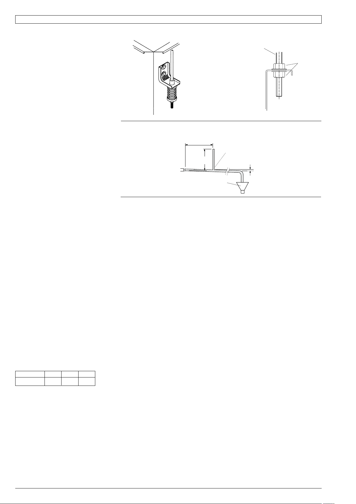
If a more rigid installation can be tolerated,
then suspend the unit from four threaded
rods using locknuts (not supplied), as shown
in Fig. 4.
1
Page 2
Mount the unit level as it comes with a
sloping drain tray. This tray is reversible
– but not if using the optional condensate
lift-pump; then the drain exit can only be at
the opposite end to the compressor.
The drain line must have a slope of at least
1 in 50 and must not be piped to a level
above the drain tray. Where required a
condensate lift-pump should be used
(optional extra).
When finally positioned, tighten the lock
nuts on the mounting rods to give a firm
installation (see Fig. 4).
Condensate Drain
The condensate drain is not to be trapped
outside the unit. The drain line must be
maintained at least 19 mm ID along its
full length. Fit a vent pipe within 500 mm
of the unit, 300 mm high and 10 mm
ID (minimum); see Fig. 5. Check drain
by pouring water into the drain tray and
ensuring that it clears. Failure to adhere to
these instructions could cause flooding.
Water Supply & Return
The HWP unit's IN and OUT water
connections are male pipe threaded (refer
Fig. 1). The two temperzone 600 mm
flexible high pressure water hoses supplied
have female pipe threaded connections at
each end. Maximum water pressure for
each hose is 1720 kPa (250 psi). The HWP
unit alone, excluding hoses, will withstand
4480 kPa (650 psi).
Poor quality water supply must be prefiltered and it is essential that adequate
water treatment is maintained, particularly
where open cooling towers are used.
Note: It is required that the water supply
system be fitted with a water flow switch and
water pump safety interlock. These items
prevent the HWP units from going into fail
safe lockout status due to a loss of water
flow. Failure to install the above items would
require the resetting of all HWP units in the
system - either by breaking the power supply
to each unit or breaking the thermostat
control circuit.
HWPSR units require a minimum water
supply temperature of 17°C.
Circuit Balancing Valve
It is recommended that a circuit balancing
valve be fitted to maintain water flow at a
constant rate. The minimum water flow rates
in litres per second (l/s) are as follows:
HWP: 35 47 58
Minimium 0.17 0.27 0.36
Electrical
The air conditioner should be connected
to the appropriate power supply for each
model, as specified in the wiring diagram,
with neutral and adequate earth. The supply
to have an accessible switch to allow
isolation of the unit. Wire the heating and
cooling room thermostat to the electrical
terminals adhering to the wiring diagram
supplied with the unit. All wiring to the air
conditioner must comply with the wiring
regulations of the local electrical authority.
Air / Water Flow
Refer to HWP 35–58 Data Sheet pamphlets
for detailed information on air handling
performance and water flow rates.
2
Fig. 3 Spring Mounting
PREFERRED
MOUNTING
SYSTEM
(SUPPLIED)
Fig. 5 Condensate Drain
500 mm MAX.
FROM UNIT
300 mm
APPROX.
NO TRAP
REQUIRED
Unit Protection
Unit protection is incorporated in either:
a.) HWP Protection Board, or
b.) SAT-2 Controller,
depending on which HWP model is being
installed.
A pump verification relay ensures that water
is flowing before the compressor will start.
A high pressure lockout protects the unit
from low water flow in cooling mode, or fan
failure in heating mode. Sensors protect
against low air coil temperature and loss of
refrigerant. Units include an anti rapid cycle
device for compressor protection.
HWPSR units also have a low refrigerant
temp. safety thermostat to protect against
icing up of the water within the unit's tube-intube heat exchanger.
A non-specific fault LED/ output signal is
also included for remote fault indication to
building management systems (refer wiring).
Note: Lockout protection can be reset by
switching unit's power supply off and on.
Lockout protection will also reset when the
thermostat switches, or is switched to the
dead zone.
Units Supplied With SAT-2 Thermostat
Any faults detected are displayed on the
SAT-2 Wall plaque (refer Table 1). A nonspecific fault output signal is also included on
SAT-2 Controllers for remote fault indication
to building management systems.
Units Supplied With Electric Heat
HWPSCEKS models supplied with electric
heat include both auto (90°C) and manual
(120°C) high temp. safety thermostats. If the
manual safety t/stat requires resetting, then
the auto safety t/stat has failed and needs to
be replaced.
Fig. 4 Solid Mounting
MOUNTING
ROD
VENT PIPE (10 ID)
FOR LONG
CONDENSATE
DRAIN RUNS
MINIMUM
SLOPE
20 mm PER m
OPEN
DRAIN
(1 IN 50)
Room Thermostat
(Reverse Cycle Models)
The thermostat should be set within the
recommended operating range of between
19°C and 30°C. The thermostat should
not be used as an on-off switch. Refer to
temperzone for a list of other approved
thermostats.
If your unit is supplied with temperzone's
SAT-2 Thermostat, refer to page 3 for
installation instructions.
COMMISSIONING
1. Check that the thermostat is correctly
wired and set at the desired temperature.
2. Check that the air filter (if fitted) is clean.
3. Check that the fan runs freely without
vibration.
4. Check condensate drain and safety drain
tray for free drainage.
Demonstrate the SAT-2 Wall Control (if
supplied) to the owner/user, after having
first thoroughly familiarised yourself with the
User's Operating Instructions. This page is to
remain with the owner/user.
MAINTENANCE
Quarterly
1. Remove lint and dust accumulation from
heat exchange air coil. (Note: failure to
do this may affect efficiency).
2. Check air filters and vacuum or wash
clean as necessary.
3. Check condensate drain for free
drainage.
4. Check compressor compartment for oil
stains indicating refrigerant leaks.
5. Check quality of water supply.
Six Monthly
Check tightness of electrical connections.
Yearly
1. Remove lint and dust accumulation from
heat exchange air coil. (Note: failure to
do this may affect efficiency).
2. Replace air filter if damaged to maintain
adequate air flow and efficiency.
TIGHTEN
LOCKNUTS
FOR
STRENGTH
Page 3

Units Supplied With Integrated Thermostat (SAT-2 Controller)
Components
The following components are supplied in a
box taped inside the supply air spigot:
1. SAT-2 Wall Control plaque, including wall
mounting plate.
2. 10 m interface lead (electrical box-toplaque).
3. User's Operating Instructions booklet.
4. Lithium CR2032 battery (3V).
Optional
1. Remote return air sensor (in box).
2. Remote return air temperature sensor
lead; 1.5, 6, 12 or 25 m.
3. 20 m extended interface lead
(electrical box-to-plaque).
4. SAT-2 Zone Control PCB.
5. Zone Control 24V transformer.
6. Additional SAT-2 Wall Control plaque.
7. Infra red remote control.
Installation
The SAT-2 Controller PCB is supplied preinstalled in the HWP unit's electrical box.
1. Isolate the HWP unit from power supply,
then remove electrical box cover.
2. Remove the SAT-2 box supplied taped
inside the supply air spigot.
3. Remove the Wall Control's interface lead
from this box and connect to the terminal
block (A1/B1/Vcc/GND) on the SAT-2
Controller board. Trace the remaining
length of the lead to the Wall Control's
intended location. Note: Make sure the
coloured wires are connected as per the
wiring diagram.
4. Remove the Wall Control's backing plate
by using a small screw driver to remove
the single screw at the bottom edge of
the plaque.
5. Install the Lithium battery, supplied loose,
positive (+) side up in the Wall Control's
battery holder.
6. Check the wall where the Wall Control
plaque is to be located is flat before
fastening the wall mounting plate.
Alternatively, the mounting plate can
be screwed to a standard wall socket
mounted horizontally.
Note: Use low profile (mush) headed
screws to prevent contact with the PCB
board. Fixing the plate to a distorted
surface may damage the control.
7. Drill hole in wall to allow cable entry.
8. Connect the interface lead to the the
Wall Control board. Note: Make sure
the coloured wires are consistently
connected at each end as per the wiring
diagram.
9. Ensure the interface lead is run
separately and away from main
power supply wires, including the
interconnecting cable. When installing
cabling, trim any excess length to suit
your location.
10. Fill around the interface lead with foam
or cover hole with PVC tape to prevent
draft from wall cavity affecting control
operation. Do not use aluminium duct tape.
11. Secure the Wall Control body to the
mounting plate by replacing the locking
screw removed earlier.
12.Replace the HWP electrical box cover.
Water Valve Control Option
Once the SAT-2 room thermosat reaches
the desired room temperature, it is capable
of switching off both the HWP unit's
compressor and an external water control
valve (if fitted); refer wiring diagram. This
provides economy of operation by reducing
the load on the central water supply system.
Remote Air Temperature Sensor/s
(option)
The air temperature sensor is by default
located in the Wall plaque. Optional remote
air temperature sensors are available
so that the measurement of the room
temperature can be taken away from the
wall plaque, eg. elsewhere in the room or in
the return air duct.
Remote sensor's can be plugged directly
into the Controller board (PCB). This
board accepts up to four sensors which
are designated as 'zones' one to four. The
first return air sensor will automatically
replace the Wall Control sensor and should
be located in the same room as the Wall
Control. The Controller will always use the
average of the zones selected. Refer to the
separate installation instructions supplied
with the PCB for further details.
Ensure all remote sensor wires are run
separately and away from main power
supply wires, including the interconnecting
cable.
Table 1 SAT-2 Controller - Troubleshooting
If an fault is detected, an 'ERR' symbol will light up on the Wall plaque display.
The following error codes may be displayed:
Error Code Fault Remarks
1 Room sensor #1 failure Main board AD3
2 Room sensor #2 failure Main board AD4
3 Room sensor #3 failure Main board AD5
4 Room sensor #4 failure Main board AD6
5 #1 indoor coil sensor failure Main board AD1
6 #1 LST sensor failure Main board AD2
7 #1 insufficient refrigerant
8 #1 compressor overload
9 #1 low pressure failure
10 #1 high pressure failure
11 Room sensor #5 failure At wallpad B
12 Room sensor #6 failure At wallpad A
13 All room sensor failure
14 Float switch failure
15 #1 Low safety thermostat failure
16 Communication failure
17 Hydronic pump switch failure
18 #2 insufficient refrigerant
19 #2 compressor overload
20 #2 Low safety thermostat failure
21 Discharge sensor 1 failure
22 Discharge sensor 2 failure
23 Discharge temp 1 failure
24 Discharge temp 2 failure
Fault Detection
Any faults detected are displayed on the
SAT-2 Wall plaque (refer Table 1). A nonspecific fault output signal is also included
on SAT-2 Controllers for remote fault
indication to building management systems.
NOTE
The manufacturer reserves the right to
make changes in specifications at any time
without notice or obligation. Certified data is
available on request.
This pamphlet replaces the previous
issue no. 3669 dated 12/12.
CKSD & RKSD wiring rev.'s L & J resp.
3
Page 4

Fig. 6 Application Considerations
Recommendations for Noise Isolation:
1. Avoid installing units, with non-ducted return air, directly above
spaces where noise is critical.
2. Use flexible connections between unit and rigid ducting.
3. Use generously sized acoustically lined ducts.
4. If generous duct size is not possible, use turning vanes on bends
to reduce air turbulence (regenerated noise).
5. Use 90° bends in ducting to significantly assist in noise reduction.
4
Page 5

HWP 35–58 CKSD & CEKSD
5
Page 6

HWP 35–58 RKSD
6
Page 7

HWP 35–58 CKSN & CEKSN
7
Page 8

HWP 35–58 RKSN
01/14 Pamphlet No. 3669
© temperzone ltd 2014
 Loading...