

Page 1
Owner’s Manual
Models: TC-12B - TC-60B4, Digital Thermostat
Unit Specifications .......................................................................................... 2
1-800-836-7432
Warning!
Improper installation, adjustment, alteration, service, or
maintenance can cause injury
or property damage. Please
read instructions before installing, operating or servicing the
TEMP-COOL unit.
Avertissement !
Le fait de modier ou de mal
installer, régler, réparer ou
entretenir cet appareil peut
entraîner des blessures ou des
dommages matériels. On doit
lire attentivement les directives
d’installation, d’utilisation et
d’entretien avant de manipuler
l’unité TEMP-COOL
Rating Information ........................................................................................... 2
Inspection ......................................................................................................... 3
General Description ......................................................................................... 3
Standard Features ..........................................................................................3-4
Optional Features ............................................................................................. 4
Installation Instructions .................................................................................4-5
Unit Operation ..............................................................................................5-6
Preventative Maintenance .............................................................................6-7
Troubleshooting Guide .................................................................................8-9
Installing Replacement Parts ....................................................................10-11
Accessories .................................................................................................... 12
Replacement-Parts List .............................................................................13-14
Wiring Schematic, TC-12B ........................................................................... 15
Wiring Schematic, TC-18B ........................................................................... 16
Wiring Schematic, TC-24B ........................................................................... 17
Wiring Schematic, TC-36B ........................................................................... 18
Wiring Schematic, TC-60B ........................................................................... 19
Wiring Schematic, TC-60B3 ......................................................................... 20
Wiring Schematic, TC-60B4 ......................................................................... 21
This manual is the property
of the owner. Leave with the
unit when set-up and start-up
are complete. TEMP-AIR
Inc. reserves the right to
change design and specications without prior notice.
Page 2
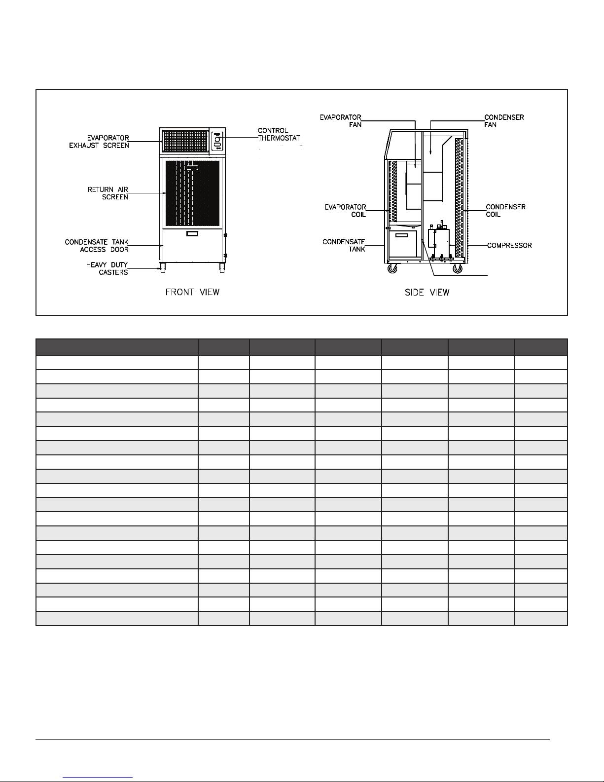
Unit Specications/Rating Information
HIGH PRESSURE
SWITCH
Specifications TC-18B TC-24B TC-36B TC-60B TC-60B3 TC-60B4
Cooling Capacity, BTU/hr
Power Supply2 Volts/Ph/Hz/Amps 115/1/60/15 208-230/1/60/20 208-230/1/60/30 208-230/1/60/60 208-230/3/60/40 460/3/60/20
Thermostat Control Electronic Electronic Electronic Electronic Electronic Electronic
Metering Device TX Valve TX Valve TX Valve TX Valve TX Valve TX Valve
Power Consumption-Cooling, Watts 1,400 3,100 4,500 7,700 8,500 10,000
Current Consumption-Cooling, Amps 12.0 13.5 19.7 33.3 21.4 11.4
Recommended Circuit Amps 15 20 30 60 40 20
Maximum Overcurrent Protective Device, Amps --- --- --- 80 50 25
NEMA Plug Type 5-15P 6-20P 6-30P Wired Wired Wired
Evaporator CFM, Free Discharge 550 750 1,200 2,300 2,300 2,300
Condenser CFM 1,000 1,000 1,500 3,900 3,900 3,900
Maximum ESP, InWC 0.10 0.10 0.10 0.50 0.50 0.50
Maximum Duct Length, ft. 40 40 40 40 40 40
Condensate-Pump Head, ft. 15 15 15 15 15 15
Operating Limits, (min-max) ˚F 65-110 65-105 65-105 65-110 65-110 65-110
Sound Level, dB 61 63 67 71 71 71
R-410-A Charge, oz. 80 80 70 136 136 136
LxWxH, in. 28 x 23 x 47 33 x 26 x 47 30 x 28 x 51 47 x 31 x 64 47 x 31 x 64 47 x 31 x 64
Weight, net wt/shipping wt, lb. 221/279 337/375 336/395 713/775 713/775 713/775
1
17,300 29,600 41,000 75,900 75,900 75,900
1. Rating conditions: 95° F at 60% RH
2. Electrical ratings based on UL 484
TEMP-COOL
™
Owner’s Manual
Page 3

Portable Cooling Systems
INSPECTION
1. Inspect unit on delivery.
2. Compare unit received with description of product
ordered.
3. Report any damage to the delivery carrier.
4. Request a written inspection report from the Claims
Inspector to substantiate claim.
5. File claims with the delivery carrier.
GENERAL DESCRIPTION
TEMP-COOL Portable Cooling Systems are designed
to spot cool industrial, commercial, institutional and
construction sites. Six models provide from 17,300 to
75,900 BTU/hr. of cooling and from 1740 to 7000 watts
of electric heat. Options include discharge nozzles to
direct conditioned air precisely where needed, and exible duct to transfer condenser hot air either outside or to
an adjacent area.
TEMP-COOL Portable Cooling Systems are completely
self-contained and housed within an insulated cabinet.
The units’ exterior is constructed of galvanized steel and
protected with a tough powder-coated, polyester nish.
All models are equipped with standard heavy-duty casters
for portability.
STANDARD FEATURES
Serviceability
Normal maintenance for the TEMP-COOL Portable
Cooling Systems requires a minimum amount of effort. The two air lters that cover the coils can easily be
inspected and replaced by removing the grilles holding
them. The TC-18B through the TC-36B have an internal
condensate tank that must be emptied when full. The tank
is in a rollout drawer mounted on ball bearing drawer
slides. The large TC-60B units have an integral condensate pump, with a condensate tube that must be run to a
drain or container.
All of the other components, which are normally
accessed for troubleshooting or replacement, can be
accessed by removing the side panels or top cover. The
electrical control panels can readily be accessed from the
exterior of the unit through access doors. On the TC-18B
through TC-36B the high head pressure reset switch can
be accessed by opening the condensate tank drawer and
pressing the button located on the back wall of the enclosure. On the TC-60B units the reset button is located
in the cord pocket enclosure, which is accessible from
outside the unit.
High-Pressure Safety Switch
All models feature a manual reset, high-pressure switch.
If the refrigeration circuit exceeds the controls pressure
setting, power to the compressor and other critical components is cutoff to prevent damage to the unit.
Note: Determine the reason for the the trip and correct
the problem before resetting the switch (See the
troubleshooting section for suggestions. Wait four
minutes before attempting to reset.)
Digital Temperature Control System
The digital temperature control system allows the user
to select Cooling or Fan Only operating modes. It also
allows the unit to be started or stopped after a predetermined period. The control also has internal functions
that prevent the cooling coil from freezing, prevent the
compressor from cycling excessively and provide a
heating element cool down function when in the heating
mode. See the section covering the operation of the unit for
additional information on the Digital Temperature Control.
Filters
All units are equipped with removable, disposable,
pleated media lters. Located behind the return air and
condenser intake air grilles, they can be removed for
inspection or replacement by removing the grille.
Condensate Tank
The TC-18B through TC-36B are furnished with a ve
gallon, polyethylene condensate tank located in the
drawer on the lower front of the unit. The tank collects
the moisture that condenses on the cooling coil when the
unit is in operation. When full, a magnetic oat in the
tank closes a magnetic proximity switch located above
the tank inside the unit, turning the unit off and causing
“tF” to be displayed on the front panel of the unit. The
condensate tank must be emptied and reinstalled to allow
further operation.
Note: The unit will not operate unless the tank is
drained periodically. Optional condensate pumps
are available that allow continuous operation,
but require a tube to be run from the pump to a
suitable drain.
3
Page 4
Condensate Pump
G
X
W
Y
G
G
G
G
X
W
Y
G
G
Due to the large amount of condensate produced by the
TC-60B models, condensate tanks are not furnished or
available on these units. Condensate pumps are furnished
as standard on the TC-60B models, and must be piped to
a suitable drain.
Cord Kit (LCDI) (TC-18B, 24B, 36B)
The LCDI cord kit provides both personal shock as well
as cord arcing and re protection. The LCDI cord kit is
preinstalled and must be replaced with an identical cord
kit, available from Temp-Air, Inc., if damaged or if it fails
to operate properly.
INSTALLATION INSTRUCTIONS:
Before Installing:
Check unit for damage. Air conditioners are inspected at
the factory. If any damage has occurred, save the packaging and le a claim with the delivering carrier within fteen working days. TEMP-COOL units require minimal
installation. The smaller units (TC-18B though TC-36B)
can be plugged into the proper receptacle, and are ready
to run immediately. The larger TC-60B units must be
wired to a plug or power source, and the condensate hose
run to a suitable drain or outdoor location before starting
the unit.
OPTIONAL FEATURES:
See “Accessory” section on page 12 for the correct
accessory part numbers.
Condenser Duct:
Condenser discharge air can be removed from the con-
ditioned space with exible duct. Use 40 feet maximum
for all models. Allow six feet for every 90˚ bend. Do not
exceed 0.10 in. w.c. external static pressure at the condenser.
Ceiling Panel Duct Kit:
A ceiling panel duct kit comes complete with exible
duct and a 2 foot by 2 foot ceiling tile adapter, which allows condenser air to be vented to the plenum area above
a suspended ceiling.
Discharge Nozzle Kit:
A dual-nozzle, discharge air assembly optimizes the abil-
ity to direct cool air precisely where needed. The exible
nozzles are attached to a mounting plate that ts over the
evaporator air grille.
Condensate Pump:
A condensate pump automatically drains from the
condensate pan by removing evaporator coil condensate
water allowing continuous operation. The pump must be
connected to the condensate drain and to the air conditioner’s power supply. A hose must be run from the unit
to a convenient drain or outdoor location.
Condensate pumps are standard on the TC-60B models
and optional on all others.
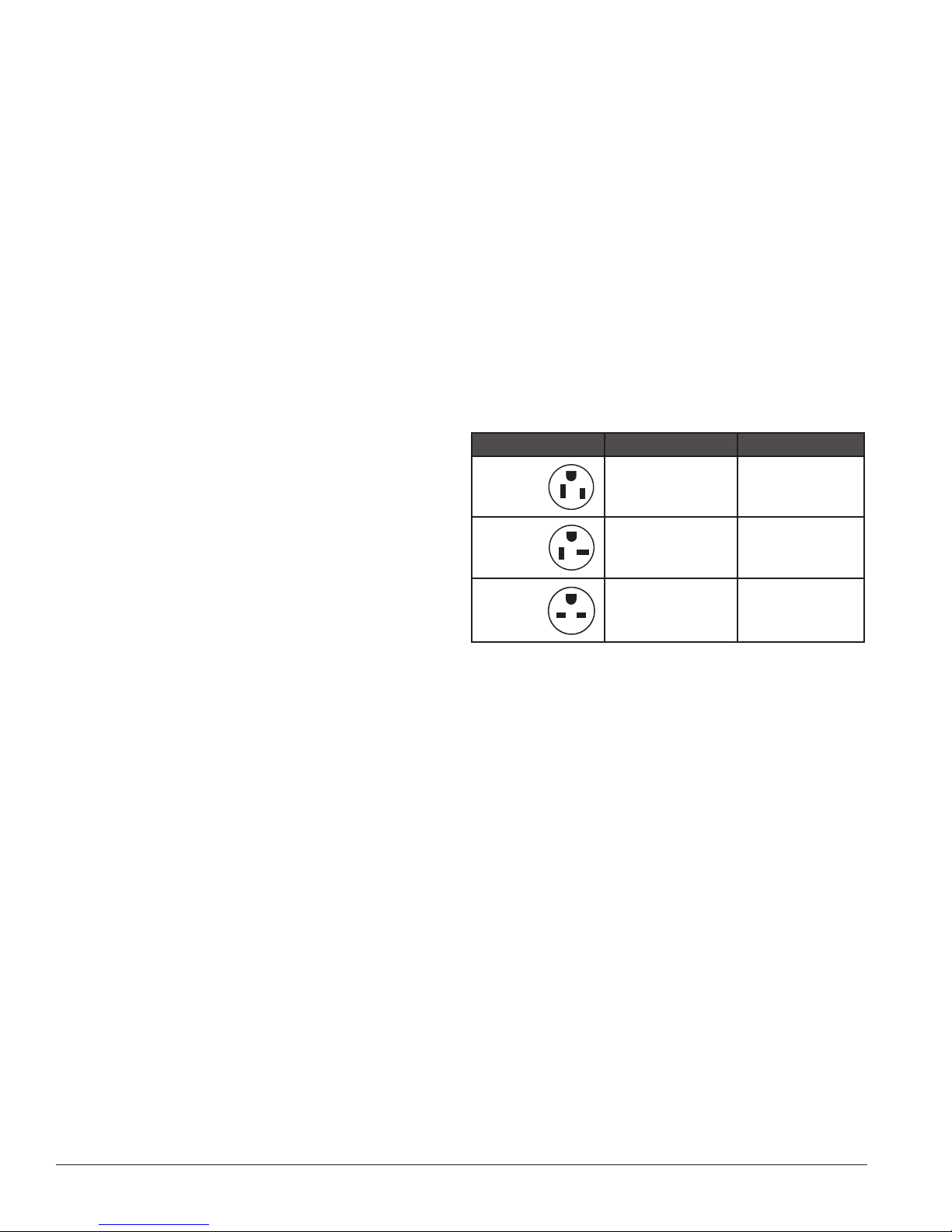
Model Plug Configuration Receptacle
TC-18B
115V
TC-24B
208-230V
TC-36B
208-230V
W
G
X
G
G
15A/115V
NEMA 5-15P
20A/230V
NEMA 6-20P
30A/230V
NEMA 6-30P
NEMA 5-15P
NEMA 6-20P
NEMA 6-30P
Electrical Supply:
Determine the proper power by checking the unit’s rating plate. For the models from the TC-18B through the
TC-36B use the wall outlets and receptacles shown in the
table above. For the TC-60B, B3 and B4, the units must
be wired to a suitable power supply using the appropriate
cord and circuit protection for the electrical ratings on the
nameplate.
Operating the units at an improper voltage, frequency, or
improper phase orientation (see TC-60B3 and 4 – 3 Phase
Wiring Instructions below) voids the warranty.
Note: Extension cords may be used if rated at a
minimum of 120VAC at 20 amps for the model
TC-18B, 230VAC at 20 amps for the model
TC-24B, and 230VAC at 30 amps for the model
TC-36B. All extension cords must have a
functional grounding connector and t the LCDI
cord supplied with the unit.
Extension cords cannot be used on the TC-60B
models.
TEMP-COOL
™
Owner’s Manual
Page 5

Portable Cooling Systems
TIMER SLEEP
HOUR TEMP
HOUR TEMP
MODE
COOL
FAN
TC-60B3 and B4 – 3 Phase Wiring Instructions:
Only qualied personnel should install TC-60B units.
Extra care is required on the three phase units, the TC60B3 and TC-60B4, to insure they are connected in phase
with the incoming power. If the unit is not in phase the
condenser fan and compressor operate in reverse and
damage the compressor. If the unit is not in phase with
the power supply, the compressor will make more noise
than normal and the condenser fan will deliver very
little air. The evaporator fan can not be used to check the
phase. It has a single phase motor that operates in the correct direction regardless of the phase sequence.
or outside location. Do not crimp or bend the tubing,
or place it where something might be set on the
tubing restricting its ow. No portion of the
discharge tube should be more than 10 feet above the
level of the pump.
5. Attach any required accessories and ductwork.
6. Plug in or wire the unit to an acceptable power source.
7. When power is applied 06 should appear briey on
the control display and disappear. The unit is now
ready for use.
Cooling Operation:
1. Press the POWER BUTTON to start the unit. The
evaporator (cooling) fan will start and the current
space temperature will be shown on the digital
display. The unit will start in the last mode used.
2. Select the Cooling mode by using the MODE button
to step through the three available modes (Cool, Heat
and Fan) until the cooling mode indicator light comes
on. The unit is now in the cooling mode.
If the wiring phase sequence is incorrect, reversing any
two of the three incoming power leads will solve the
problem.
UNIT OPERATION:
Placing the Unit:
1. Locate the unit on a at, level service.
2. Keep entering and leaving air openings free of
obstructions. Maintain at least 18” of clearance
between air inlet or outlet and any wall or other
obstruction.
3. For a unit with a condensate tank, check the tank
to make sure it is in place and empty.
4. For a unit with condensate pump, make sure the
condensate discharge tubing is connected to the outlet
connection of the unit and runs to a suitable drain
3. Press the Up or Down temperature button to see the
current cooling setpoint temperature. Adjust the
setpoint temperature to the desired value by pressing
the Up or Down temperature button repeatedly, until
the desired temperature is reached. The display will
ash six times at the new setpoint then the actual
room temperature will be displayed. In the cooling
mode up to ve minutes may lapse between turning
the unit on or resetting the temperature and the
compressor starting. This delay is a result of the anti
short cycling program in the thermostat. A green dot
will appear in the lower right hand corner of the
temperature display when the compressor is being
energized.
4. The compressor and condenser fan will continue
to operate until the space temperature drops to the
setpoint temperature. At that point the compressor
and condenser fan will shut off, but the evaporator
fan will continue to run until the unit is turned off.
Fan Operation:
1. Press the POWER BUTTON to start the unit. The
evaporator (cooling) fan will start and the current
space temperature will be shown on the digital
display. The unit will start in last mode used.
2. Select the Fan mode using the MODE button to step
5
Page 6

through the two available modes (Cool and
Fan) until the fan mode indicator light comes on. The
unit is now in the Fan mode.
3. Pressing the Up or Down temperature buttons has no
effect on the temperature display, since neither the
cooling nor heating functions are active. The tempera-
ture display displays the current room temperature.
4. To stop the fan, turn the unit off using the power
button.
OTHER FUNCTIONS:
PREVENTIVE MAINTENANCE:
TEMP-COOL air-conditioning units provide high performance and reliability with a minimum amount of maintenance. To prolong the life of the unit and insure a high
level of performance, perform regular maintenance as
described below.
The refrigeration and electrical circuits of the
systemshouldbeservicedbyqualiedtechnicians
only. Always disconnect the unit from its
power supply when performing any form of service
requiring the removal of grilles or panels.
Timer ON/OFF:
Use the following instructions to turn the unit ON or OFF
after a period of up to 15 hours.
1. To turn the unit ON after a preset period press the
TIMER button, while the unit is OFF. The display
will ash ve times showing the current delay time in
hours. If a different time delay is required press the
Up or Down Hour buttons until the desired delay time
is displayed. This number can be any whole number
between 1 and 15 hours. When the desired value is
displayed release the key. The selected value will
ash ve times and go blank, but the TIMER light
will remain on. The unit will start in whatever mode
it was in before the timer was set after the specied
delay time. Once set, the timer function can be
cancelled by pressing the TIMER button again.
2. To turn the unit OFF after a delay follow the same
procedure as turning the unit ON after a delay except
start by pressing the TIMER button when the unit is
running. The display will ash the OFF delay time
ve times, then the display will revert back to the
normal temperature display. The timer light will be
on when the OFF delay is active. The delay can be
canceled by pressing the TIMER or turning the
unit OFF.
Sleep:
Press the SLEEP button to raise the setpoint temperature
1˚F when in the cooling mode one hour after the button is
pressed. The unit will run in this mode until it is canceled
by pressing the SLEEP button again or turning the unit
OFF.
Filters:
Dirty lters can restrict airow causing the unit to operate with a reduced efciency. Inspect the lters every six
weeks or more frequently, when operating in a dirty en-
vironment. Replace the lters when dirty with an equivalent lter. Do not attempt to clean the lters or operate
the unit without lters. On the TC-18B through TC-36B,
the lters can be removed by snapping the return air and
condenser air grilles out of the unit by pulling on the
handle at the bottom of the grille. The bottom of the grille
will snap out and the grille can be lowered a few inches
to clear the retaining tabs at the top. The lters are held
in place with plastic clips that can be rotated clear of the
lter. Reverse the procedure for replacing the lters. Pay
attention to the proper direction of air ow indicated on
the new lter.
The TC-60B lters are accessed the same as the smaller
units except the snap-in clamps have been replaced
with screws at the bottom of the grilles that have to be
removed before the grille can be detached. Additional
retainer clips are not used on the larger units. The grille
acts as the lter retainer.
Coil Cleaning:
If the coil becomes dirty it can be cleaned using a vacuum followed by compressed air. Vacuum the face of the
coil where the air enters the coil. Most of the dirt will
be on this side. Use compressed air to blow any remaining dirt out. Work from back to prevent driving the dirt
further into the coil. Keeping clean air lters in place will
greatly reduce the frequency that coils must be cleaned.
Blowers and Blower Motors:
There is nothing that can be serviced on these components other than inspecting the blowers and blower motors to insure they are clean. The blower and motor bear-
TEMP-COOL
™
Owner’s Manual
Page 7

ings are lubricated and sealed at the factory, and require
no additional lubrication. Dirt on the blower wheels can
be cleaned off with a rag. Dirt should not be a problem if
the air lters are properly maintained and kept in place.
Belt Tension, (TC-60B, 60B3, 60B4 Models only)
The condenser fan on the TC-60B series of air conditioners uses the only blower/motor combination that incorporates V-belts drives. The condition of the belt, along
with its tension and alignment should be checked at least
once a year for proper operation. Replace the belt if it has
cracked or is glazed. Adjust the belt tension for a 3/16”
deection of the belt with 2 pounds of force applied at the
center of the free span.
Sheave Adjustment,
(TC-60B, 60B3, 60B4 Models only)
The condenser fan on the TC-60B series of air conditioners utilizes an adjustable sheave on the motor to drive
the blower. The sheave is preset at the factory and should
not be adjusted. However the blower, motor and drives
should periodically be checked for tightness and alignment. Check the setscrews that connect the sheaves and
blower wheel to the shafts to make sure they are secure.
Make sure the setscrews locking down the adjustable
ange on the motor sheave are secure.
Portable Cooling Systems
The factory setting for the drive on the condenser fan
motor is 4 and turns open from the closed position.
7
Page 8
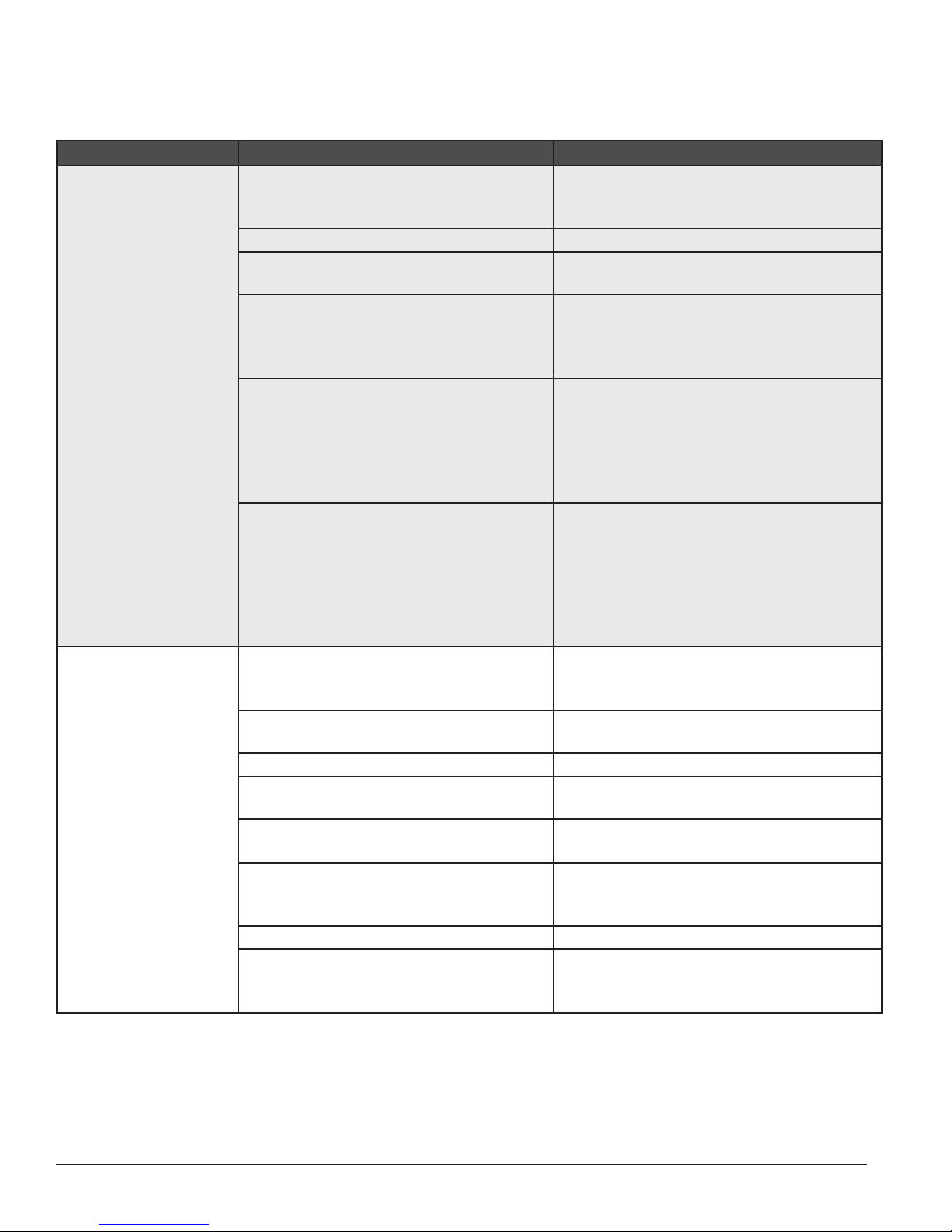
Troubleshooting Guide
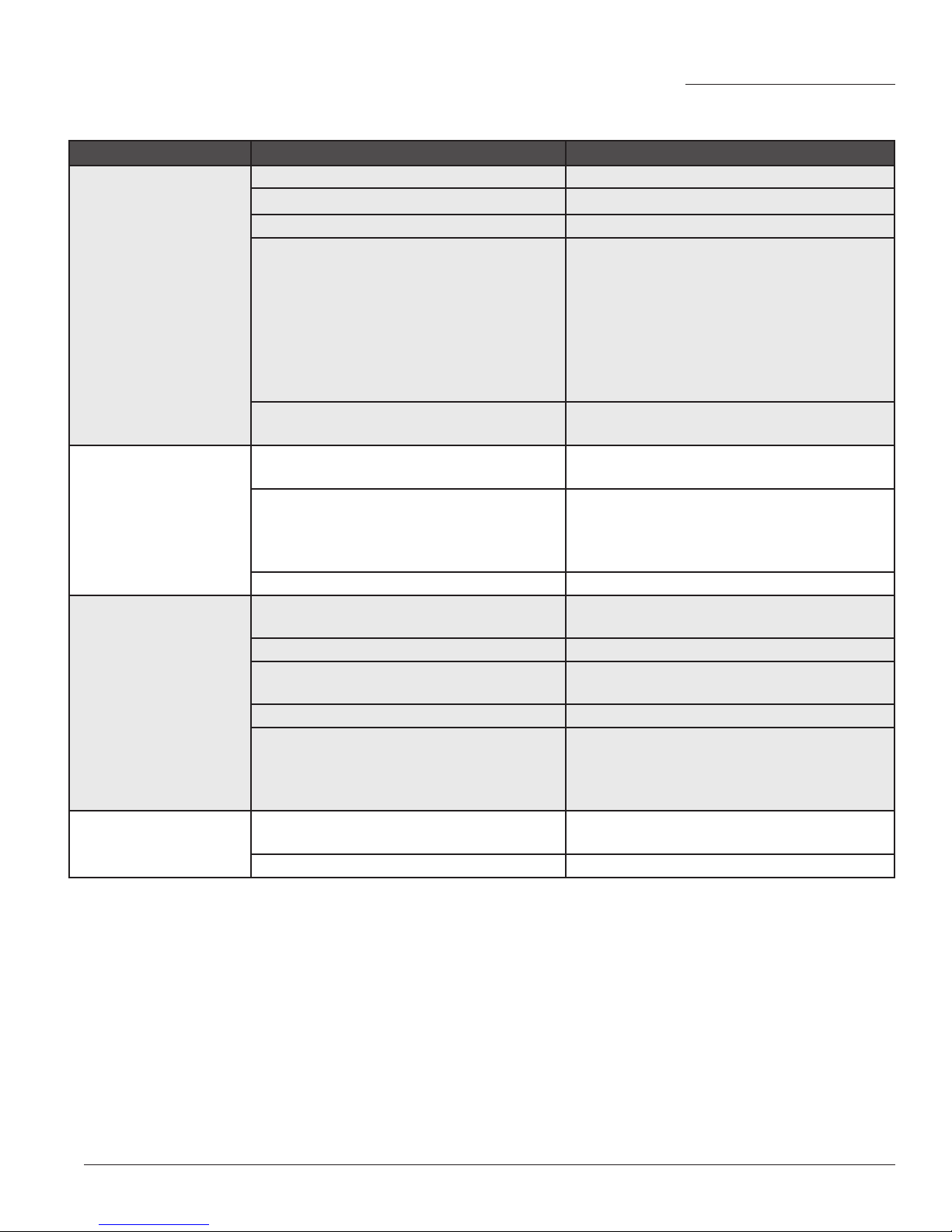
Problem Cause Remedy
Unit does not run Power interruption Check external power supply. Reset LCDI cord
control. Check circuit breakers and fuses. Replace or reset if necessary.
Condensate tank-full (tF indicated) Empty tank
Thermostat set incorrectly Check Mode setting and temperature setpoint
vs. room temperature. Reset if necessary.
Thermostat inoperable Check for display on thermostat. Press power
switch and mode switches to determine if
thermostat responds. Replace thermostat if
necessary.
Thermostat displays error code
rE room sensor failure
FE freeze sensor failure
CF compressor failure
Fr coil freezing
tF condensate tank full
Electrical Panel Problem
- 24 volt transformer defective
- Fuse blown/overload tripped (TC-60B)
- Loose wire
- Contactor coil defective
- Contactor stuck open, burned or dirty
Repair or replace room sensor.
Repair or replace freeze sensor.
Check for compressor problems.
Space too cold or refrigerant level low.
Condensate tank must be emptied
- Replace transformer.
- Check and replace or reset if necessary.
- Check and tighten if necessary.
- Replace contactor.
- Repair or replace contactor.
Evaporator fan runs but
compressor and condenser fan do not.
Thermostat satised The evaporator runs anytime the thermostat is
on. The compressor and condenser only run if
there is a demand for cooling.
Thermostat is in the compressor start delay
mode
Make sure there is a call for cooling then wait at
least ve minutes for compressor to start.
Thermostat set for the wrong MODE Set MODE to COOL.
Condensate jumper plug or condensate
pump not installed
Install jumper if a condensate tank is being
used. Attach pump if pump is used.
High pressure switch tripped or defective Press reset button on high pressure switch.
Replace switch if necessary.
Loose or defective wires Check for loose or shorted conductors. Secure
contact between wires and connectors. Repair
or replace as required.
Shorted or open run capacitor Replace capacitor.
Defective compressor Check for shorts, opens and grounds. Com-
pressor replacement should be done by a
service technician.
TEMP-COOL
™
Owner’s Manual
Page 9
Problem Cause Remedy
Compressor runs but
condenser fan does not.
Insufcient Cooling
Noisy operation Improper compressor rotation
Water leaks from pan Condensate tank or condensate pump not
Evaporator coil freezing
and unit shuts down
Loose or defective wire Trace and Repair
Shorted or open condenser motor capacitor. Replace capacitor
Bad motor Replace motor
Insufcient airow through evaporator coil
due to:
- Improper blower rotation (TC-60B3&4)
- Dirty air lter in unit
- Dirty evaporator coil
- Obstructed air intake
- Ice on evaporator coil
- Low refrigerant
Unit improperly sized Check unit against size of load. Add additional
(TC-60B3&4 only)
Loose cabinet or component part Check all panels and components to make
Bad motor, compressor, or bearing Replace as necessary.
installed.
Drain pan plugged Remove obstruction.
Loose evaporator, drain or condensate pump
hose
Leaking drain pan Repair or replace drain pan.
Defective condensate pump, obstructed
condensate hose or excessive discharge tube
height
Evaporator airow obstructed. Check for obstructions. Clean lter and coil if
Thermostat freeze protection not working Check that freeze sensor is mounted to coil.
- Check rotation. Change if necessary.
- Replace lter.
- Clean coil.
- Remove obstruction.
- Defrost. Run blower only until ice melts.
- Repair leak and recharge with proper refrigerant.
air conditioners if necessary.
Check rotation. Change if necessary.
sure they are fastened securely. Check motors,
blower wheels, drives, bearings, shafts, etc.,
and tighten as required.
Check connections and tighten if necessary.
Condensate hose run for obstructions or
excessive height above pump (12 ft. max.).
Clear or reroute tube as required. Check pump
and wiring. Replace if required.
required.
Portable Cooling Systems
9
Page 10
INSTALLING ACCESSORIES
AND REPLACEMENT PARTS:
7. Install drain hose from condensate pump outlet
through the hole in the side of the unit and route the
discharge end to a convenient drain or outdoor
location. To insure proper operation, the hose must
not be kinked or extend more than 12 feet above the
pump.
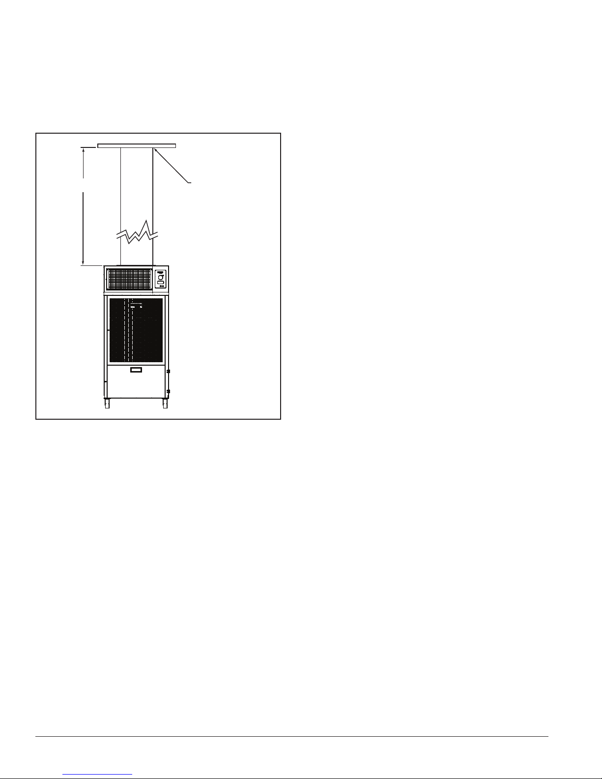
8-ft maximum
replace ceiling panel
with adapter panel
provided in kit
Ceiling Panel Duct Kit:
1. Secure one end of the duct to the ceiling-panel
adapter and the other end over the unit’s duct collar.
2. Place the ceiling panel adapter under suspended
ceiling panel’s framework directly above unit.
Condensate Pump (TC-18B, 24B, 36B only):
1. Unplug unit from power source. Remove condensate
tank and hose from drain pan.
2. Attach pump to back of drawer housing using the
screws and nuts supplied.
3. Remove the electrical plug with the jumper wire from
the receptacle located on the bulkhead in back of the
drawer.
4. Connect the condensate pump’s power plug to the
receptacle.
5. Install the hose from the drain pan to the pump inlet.
6. Remove the plug from the hole on the side of the unit.
Combination Fan and Blower,
(TC-18B, TC-24B and TC-36B only):
The blowers on these units have integral motors that are
part of the blower. They are replaced as a package. The
individual components are not available.
1. Turn the unit OFF and disconnect the power cord
from the power supply.
2. Remove the grilles, lters, side panels and top panel
from the unit.
3. Disconnect the motor wiring from the rest of the
circuit. Tag the connections and write down where
they connect, to aid in wiring the replacement motor.
4. The blower housing has to be removed to remove the
old blower. This must be done in several steps.
a. First remove the inlet side of the blower
housing from the housing wrapper, then
remove the blower housing wrapper from the
center divider.
b. The motor is attached to a mounting bracket
that is fastened to the center divider. Remove
the mounting bracket from the center divider
with the motor and blower still attached.
c. Remove the motor and blower from the
mounting bracket and attach the new motor and
blower to it.
d. Reverse the process to complete the process.
e. Make sure the blower inlet is centered in the
blower housing inlet and does not rub on the
blower housing before and after locking down
the housing.
f. Rewire the motor, double checking all
connections.
g. Plug the heater in and run it briey to insure
the fans and compressor are operating properly.
h. Unplug the unit and install the side panels, top
panel, lters and screens.
TEMP-COOL
™
Owner’s Manual
Page 11

Portable Cooling Systems
i. Plug the unit into power and test it in all
operating modes; COOL and FAN.
Condenser Fan Motor,
(TC-60B, 60B3, 60B4 only):
1. Disconnect power from the unit.
2. Remove cabinet side panels on both sides of the
condenser coil.
3. Disconnect wires from motor. Tag the wires so they
can be attached to the same terminals or wires on the
new motor.
4. Remove belt from drives.
5. Remove bolts holding motor to motor mount.
6. Remove sheave from motor and install on new motor.
7. Install new motor reversing the removal procedure.
Make sure sheave is lined up before fully securing.
8. Adjust sheave and belt tension as outlined in the
preventative maintenance section.
drop to the bottom of the housing.
7. Remove the motor mount from the motor and install
it on the new motor in the same position as the
previous motor.
8. Install new motor and blower, reversing the removal
procedure.
9. Center the blower wheel in the housing and tighten
down the set screws. Rotate the wheel to make sure it
is not rubbing on the blower housing
10. Before wiring motor to power leads make sure it is
setup for the proper voltage and rotation. Use old
motor wiring as a reference.
11. Reassemble unit and run blower. Check rotation and
amp draw before placing the unit back in service.
9. Before wiring motor to power leads make sure it is
set up for the proper voltage and rotation. Use old
motor wiring as a reference.
10. Reassemble unit and run blower. Check rotation and
amp draw before placing the unit back in service.
Evaporator Fan Motor,
(TC-60B, TC-60B3 and TC-60B4 only):
1. Disconnect power from the unit.
2. Remove cabinet side panels on both sides of the
evaporator coil.
3. Disconnect wires from motor. Tag the wires so they
can be attached to the same terminals or wires on the
new motor. Note that some of the wires are not used
but must be capped to avoid shorting them out.
4. Loosen the setscrews holding the blower wheel to
the motor shaft. Make sure the wheel is loose on
the shaft. The setscrews are accessible through the
blower housing inlet opposite the motor.
5. Remove bolts holding the motor mount to the side of
the blower housing.
6. Slide the motor and motor mount out of the wheel
and housing. The wheel is too large to pull through
the blower inlet. Let it slide off the motor shaft and
11
Page 12
Accessories
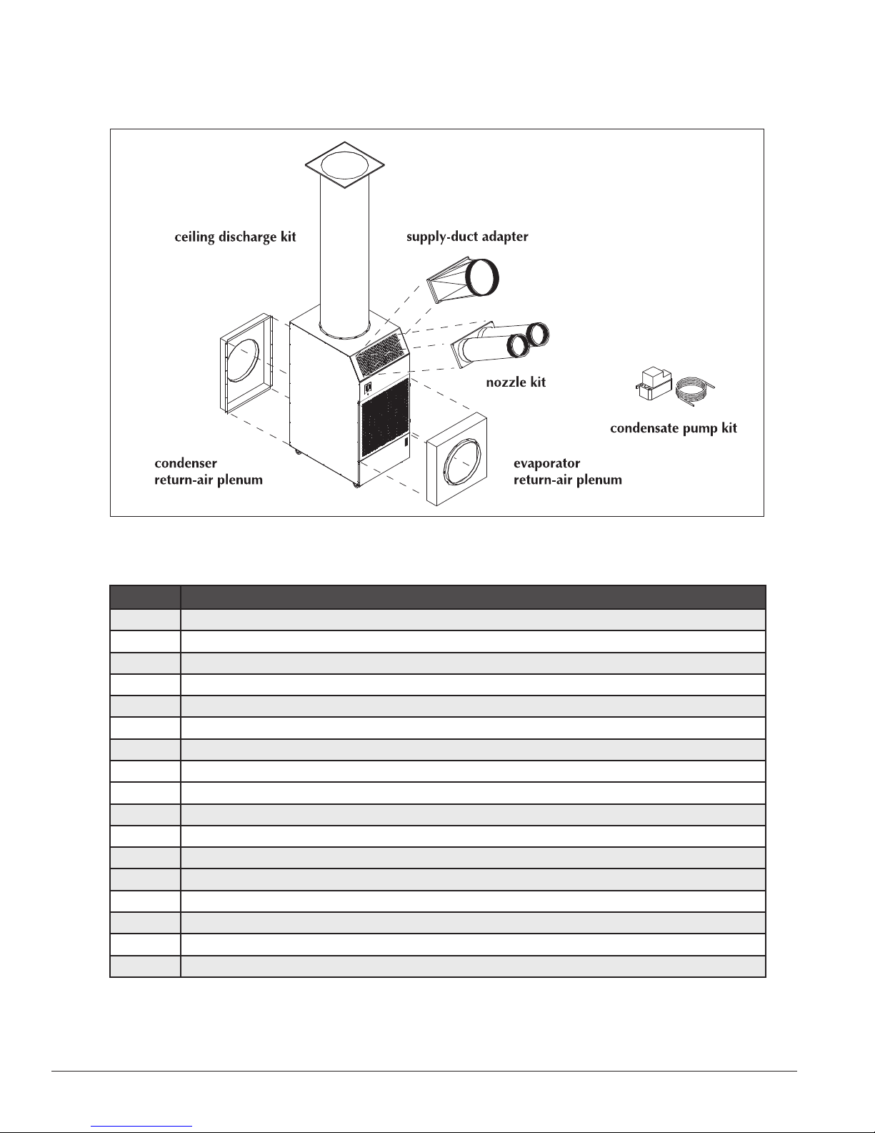
Part Description
NK-2 two, 6-in nozzles with attachment kit, TC-18B, TC-24B, TC36B
NK-3 two, 8-in nozzles with attachment kit, TC-60B, TC-60B3 and TC-60B4
CK-3 14-in ceiling discharge kit, TC-18B, TC-24B, TC-36B
CK-4 20-in ceiling discharge kit, TC-60B, TC-60B3 and TC-60B4
PC-1 condensate pump, 115 volt, TC-18B
PC-2 condensate pump, 208/230 volt, TC-24B
CP-2B 14-in condenser return-air plenum, TC-18B
CP-24B 14-in condenser return-air plenum, TC-24B
CP-36B 14-in condenser return air plenum, TC-36B
CP-4B 20-in condenser return-air plenum, TC-60B, TC-60B3 and TC-60B4
EP-2B 14-in evaporator return-air plenum, TC-18B
EP-24B 14-in evaporator return-air plenum, TC-24B
EP-36B 14-in evaporator return air plenum, TC-36B
EP-4B 20-in evaporator return-air plenum, TC-60B, TC-60B3 and TC-60B4
DA-10 10-in cold-air supply duct adapter, TC-18B, TC-24B, TC-36B
DA-14 14-in cold-air supply duct adapter, TC-60B, TC-60B3 and TC-60B4
CD-60 14-60P plug kit with 6’cord, TC-60B
TEMP-COOL
™
Owner’s Manual
Page 13
Portable Cooling Systems
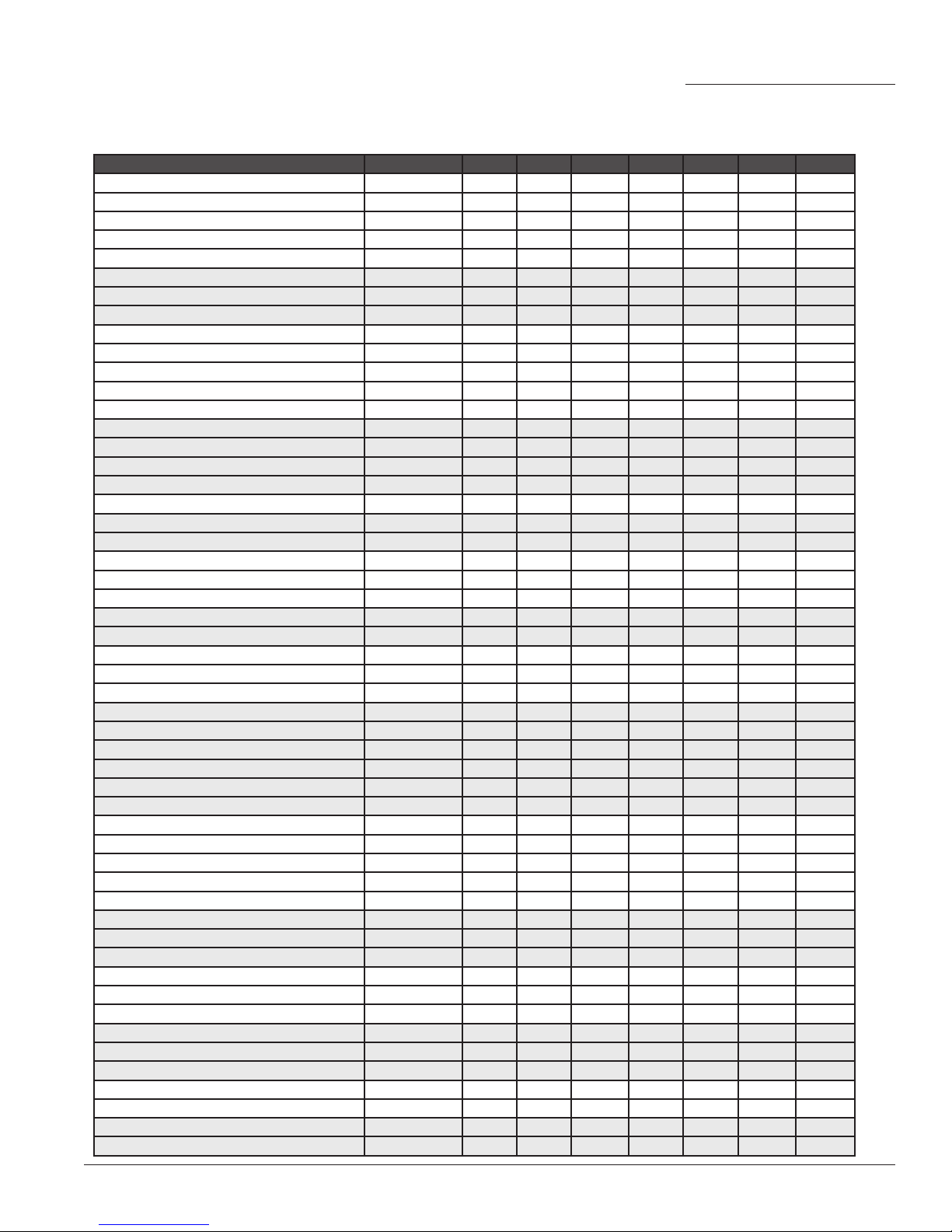
Replacement Parts List
Description
service valve, 3/8-in 88400.249
service valve, 1/2-in 88400.250
service valve, 5/8-in 88400.251
service valve, 3/4-in 88400.252
service valve, 7/8-in 88400.256
filter drier 83201.043
thermal expansion valve 88401.053
evaporator blower & motor assembly 83100.102
evaporator blower 80500.151
evaporator motor 85600.132
condenser blower & motor assembly 83100.116
condenser blower 80500.154
condenser motor 85600.145
compressor 82200.028
evaporator-motor capacitor 85601.713
condenser-motor capacitor 85601.724
compressor-motor capacitor 85601.716
supply cordset 82900.254
control transformer 88000.044
compressor contactor 87300.242
Part Number TC-12B TC-18B TC-24B TC-36B TC-60B TC-60B3 TC-60B4
83201.044
83200.169
88401.054
88401.055
88401.056
88401.057
83100.159
83100.119
83100.118
85600.139
83100.205
83100.118
80500.137
85600.217
85600.101
82200.061
82200.060
82200.071
82200.079
82200.066
85601.724
85601.021
85601.740
85601.727
85601.733
85601.713
85601.722
83100.211
82900.255
82900.257
88000.014
87300.258
•
• • • • • •
•
•
• • •
• • •
•
• • •
•
•
•
•
• • •
•
•
•
•
• • •
• •
•
•
•
•
•
• • •
•
•
• •
• •
•
•
•
•
•
•
•
•
• •
•
•
•
•
• •
•
•
• •
•
•
• • • • • • •
•
• • • •
•
13
Page 14
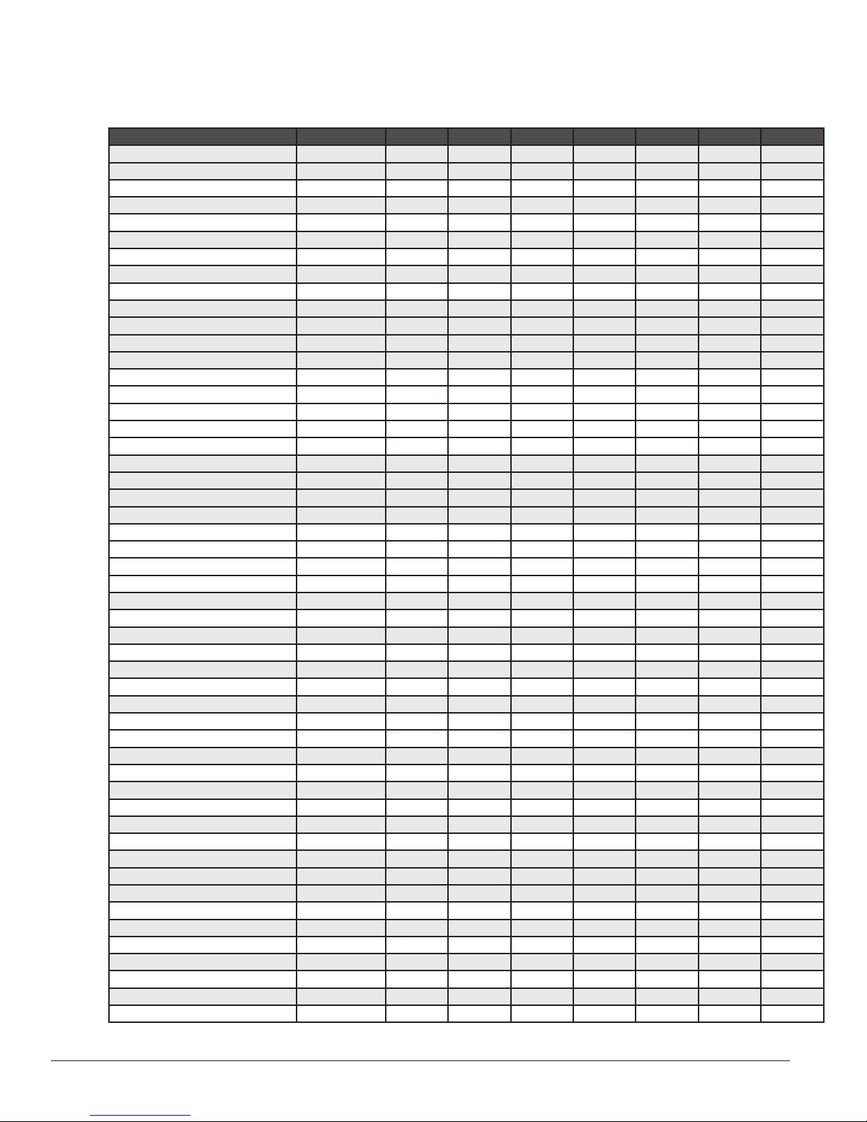
Replacement Parts List
Description
delay timer 87900.038
condensate float relay 86300.018
condensate float relay base 86300.020
filter door latch 84900.061
door handle 83800.004
magnetic switch 87500.425
condensate float 99900.721
evaporator filter 83200.201
condenser filter 83200.200
evaporator coil 81400.343
condenser coil 81400.344
3-in caster, (2) per unit 81000.051
3-in swivel caster, (2) per unit 81000.050
5-in caster, (2) per unit 81000.045
5-in swivel caster, (2) per unit 81000.046
high pressure switch 87500.424
manual thermostat 87800.102
thermostat knob 82000.081
digital thermostat 87800.888
condensate tank 99900.717
tank well cap 06000.615
spring clip, 3/8-in 81300.030
door latch - snap-in 84900.054
handle, pocket 83800.004
freeze protection control 87800.090
drain pan 84600.196
condenser motor sheave 86900.029
condenser blower sheave 86900.554
condenser blower belt 80400.212
condensate jumper plug 88800.165
2-1/2-amp fuse 83500.024
3-amp fuse 83500.055
20-amp 3 pole contactor 87300.416
Part Number TC-12B TC-18B TC-24B TC-36B TC-60B TC-60B3 TC-60B4
87300.447
87300.416
83200.203
83200.681
83200.208
83200.161
83200.202
83200.682
83200.209
81400.341
81400.305
81400.298
81400.342
81400.306
81400.299
87800.889
84600.197
99900.303
•
•
•
•
•
• • • • • • •
• • • • • • •
• • • •
• • • •
•
• •
•
• • •
•
•
•
•
•(2) •(2) •(2)
•
• •
•
• • •
•
• •
•
• • •
• • • •
• • • •
• • •
• • •
• • • • • • •
•
•
•
• • • • •
• • •
• • •
• • •
• • •
• • • • • • •
•
•
• • •
• • •
• • •
• • •
• • •
• • • •
•(2) •(2) •(2)
•(2) •(2) •(2)
•(2)
TEMP-COOL
™
Owner’s Manual
Page 15
Portable Cooling Systems
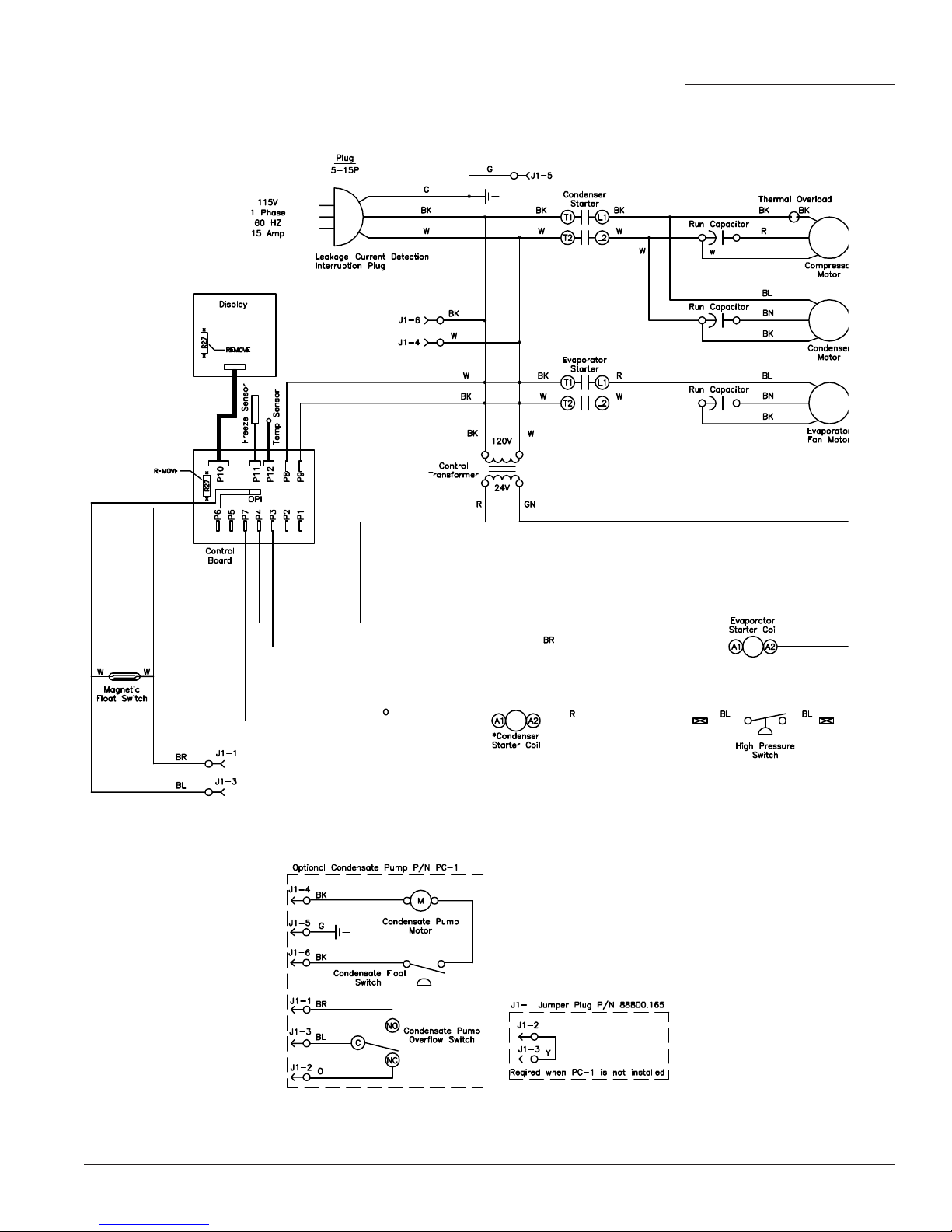
Wiring Schematic, TC-12B
15
Page 16
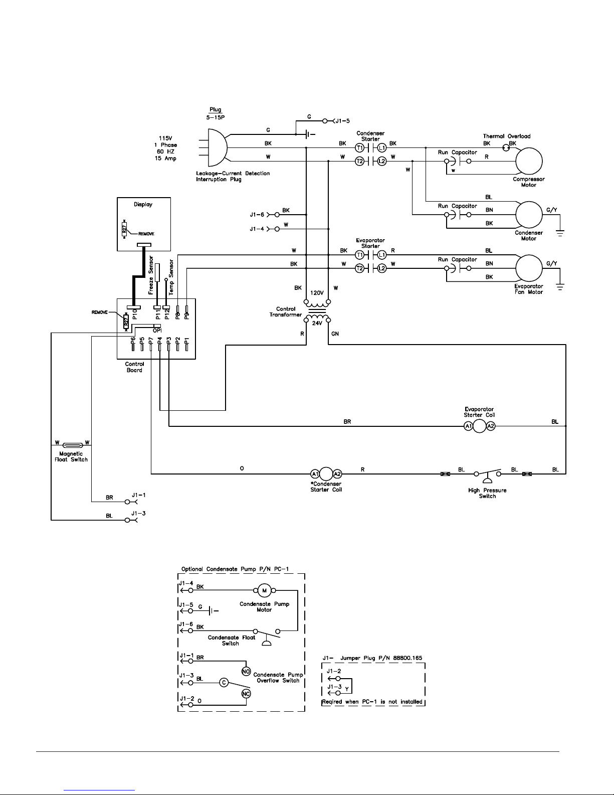
Wiring Schematic, TC-18B
TEMP-COOL
™
Owner’s Manual
Page 17
Portable Cooling Systems
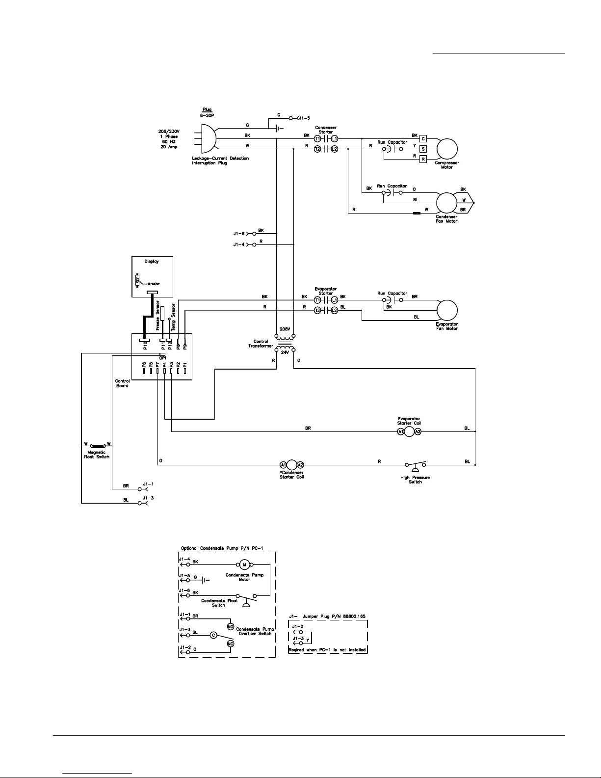
Wiring Schematic, TC-24B
17
Page 18
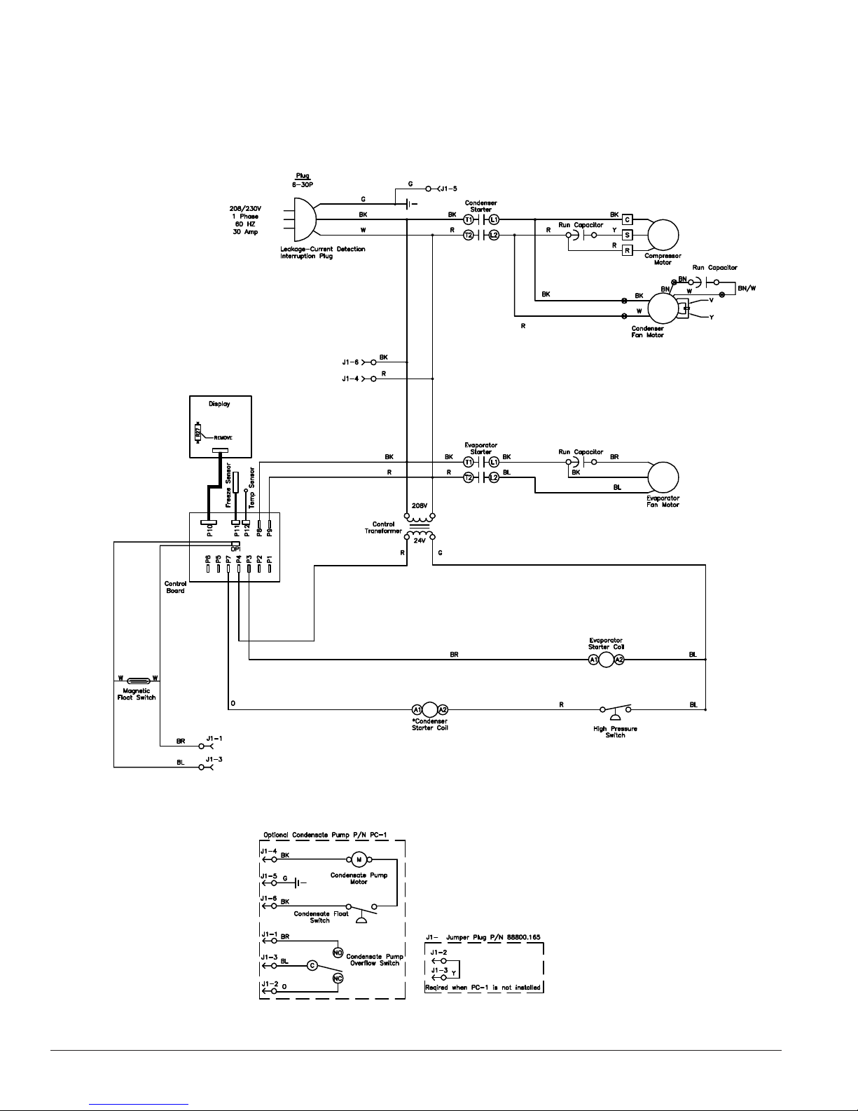
Wiring Schematic, TC-36B
TEMP-COOL
™
Owner’s Manual
Page 19
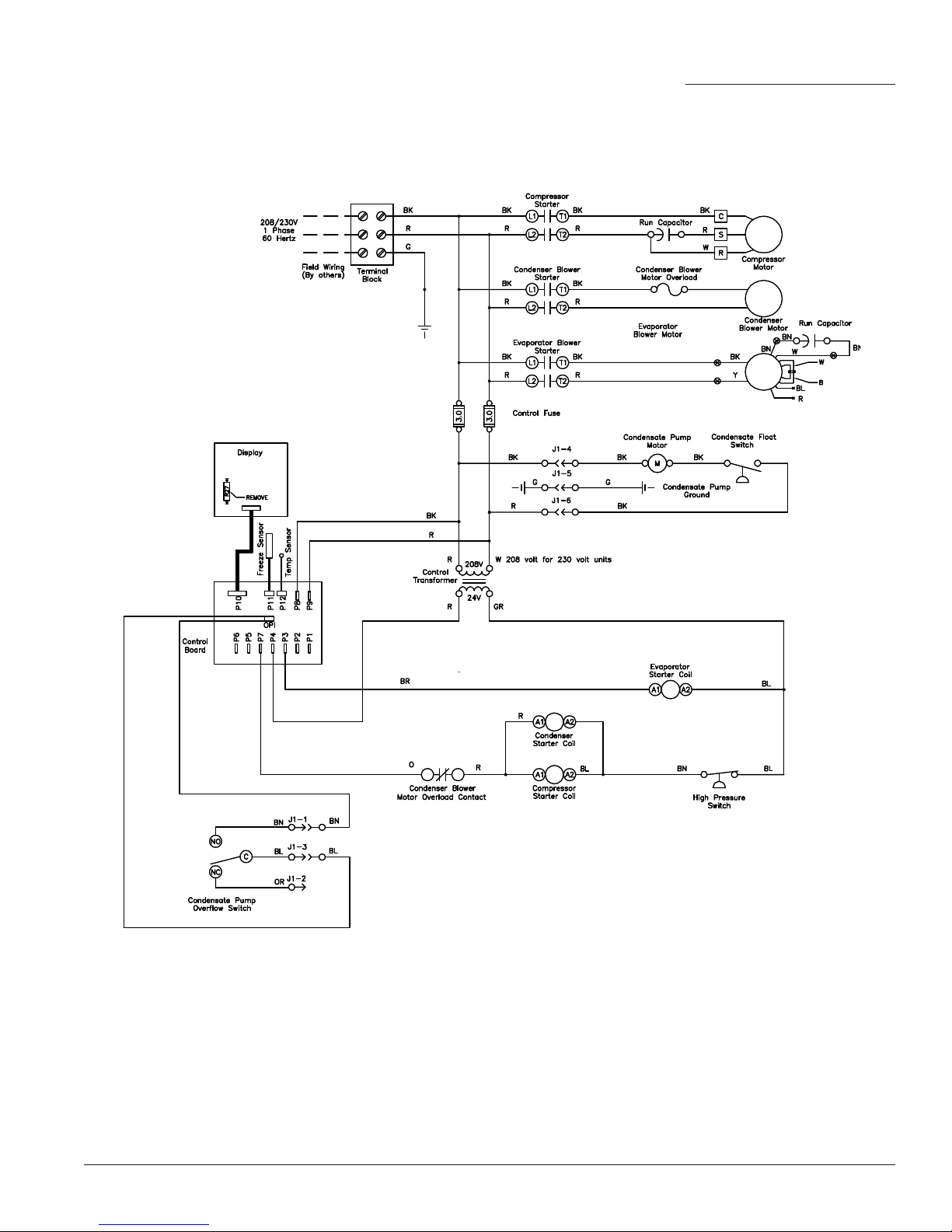
Portable Cooling Systems
Wiring Schematic, TC-60B
19
Page 20
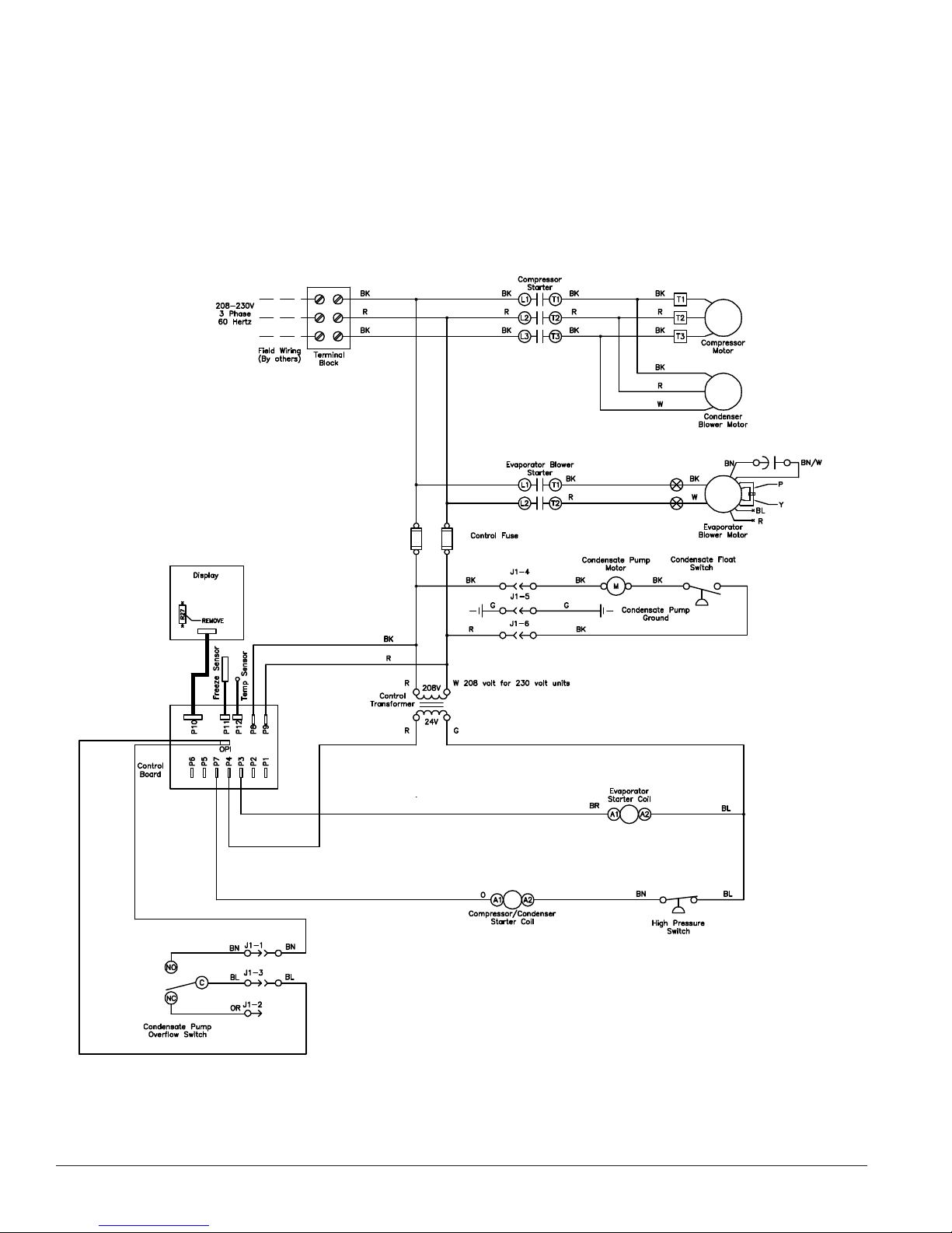
Wiring Schematic, TC-60B3
TEMP-COOL
™
Owner’s Manual
Page 21
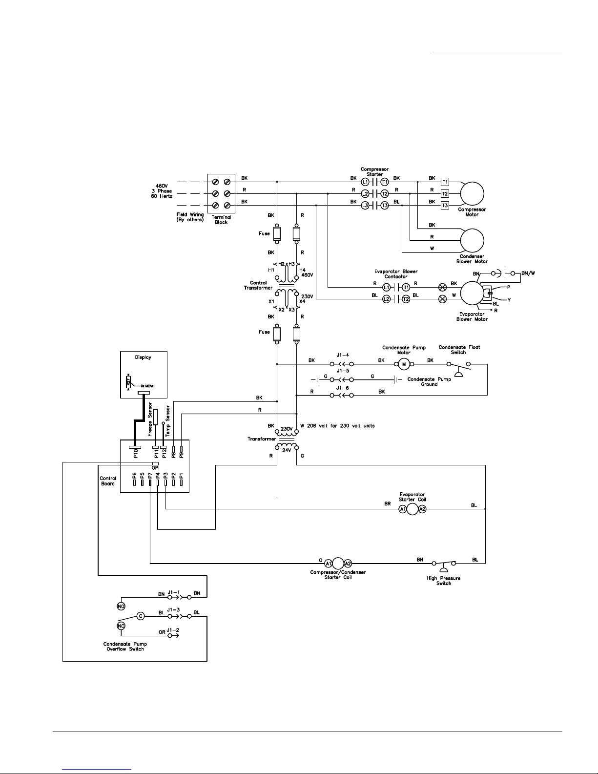
Portable Cooling Systems
Wiring Schematic, TC-60B4
21
Page 22
TEMP-AIR
3700 West Preserve Boulevard
Burnsville, Minnesota 55337-7746
1-800-836-7432
TEMP-COOL
™
Owner’s Manual
TC-MAN-BD1 © 2013 TEMP-AIR, Inc. Printed in USA
 Loading...