

Page 1
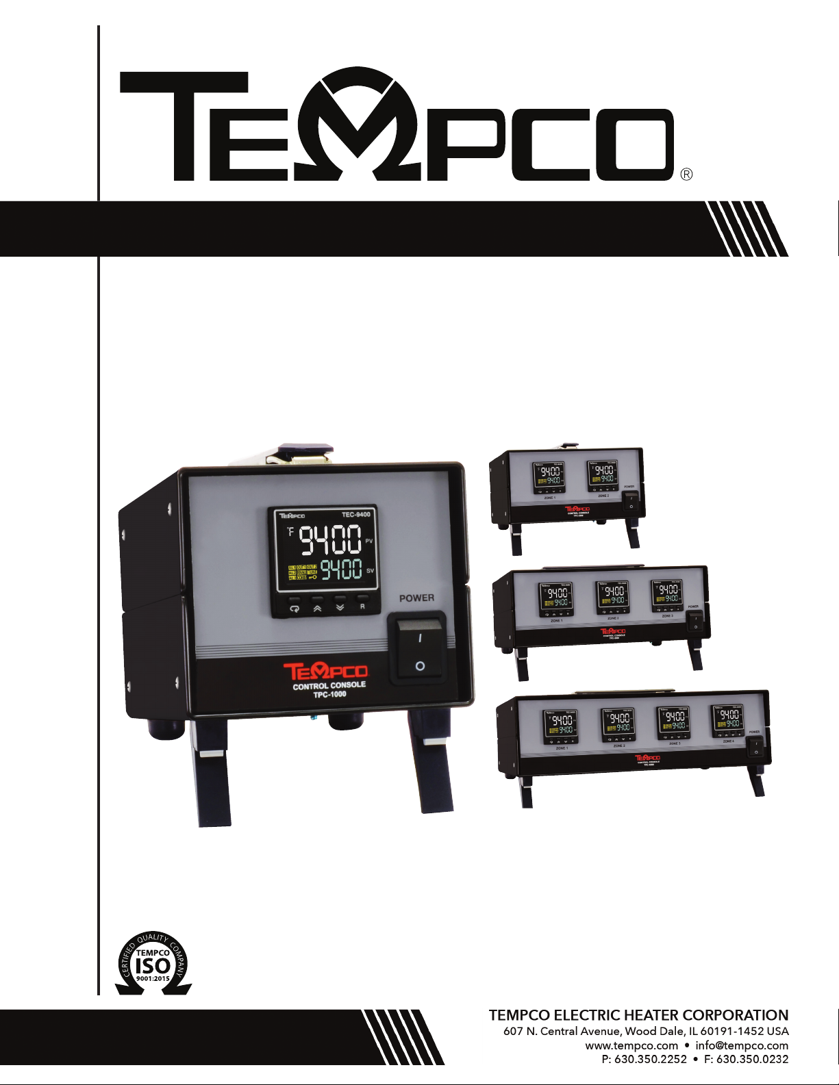
USER MANUAL
TPC-1000/2000/3000/4000 - 12 Amp
with TEC-9400 (PID + Fuzzy Logic Process Controller)
Manual TPC-1000/2000/3000/4000 - 12 Amp
D1306.TE-401-402-404-405 Revision 2/22/2019
Revision 7/19 • D1340
Page 2

SPECIFICATIONS
Temperature Controller: Model TEC-9400, 1/16 DIN Dual Display with PID Auto-tuning
Sensor Input: Type “J”, type “K” thermocouple or RTD, dependent on model ordered
(Alternative inputs available for special order)
Note: Connector body colors are as follow:
Type “J” T/C: Black
Type “K” T/C: Yellow
RTD: White
Power Cord/voltage Input: 120VAC or 240VAC (dependent on model ordered) –
Check rear label for indentification
Heater Output: 12A max for 1-zone consoles
6A max per zone for 2-zone consoles
4A max per zone for 3-zone consoles
3A max per zone for 4-zone consoles
Output Device: Solid State Relay
Main Power Switch: Located on front panel
Fuse Main Power: See replacement parts list (located inside power inlet module)
Fuse Control Power: See replacement parts list (located on back panel)
WARNINGS
1. Air vents located on top and bottom of console must not be blocked! To prevent an overheating condition
the internal components must remain as close to room temperature (75ºF / 24ºC) as possible.
2. Dangerous voltage capable of causing injury or death is present within this console. Power to all
equipment must be disconnected before installation or beginning any troubleshooting procedures. Heater
output wiring and component replacement must be made by qualified personnel only.
3. To minimize the possibility of fire or shock, do not expose this console to rain or excessive moisture.
4. Do not use this console in areas where hazardous conditions exist such as excessive shock, vibration,
dirt, corrosive gases, oil or where explosive gases or vapors are present.
5. It is strongly recommended that a process should incorporate a Limit Control like a Tempco TEC-901
which will shut down the equipment at a preset process condition in order to avoid possible damage to
products or systems.
WIRING (For safety, disconnect all power sources prior to wiring)
1. Attach the leads from your type thermocouple to the mini-plug provided. Take care to note the correct
polarity. The red lead is (-) negative.
2. The heater output current is sourced directly through the line cord. The rear console output receptacle and
mating Hubbell plug provides live controlled power for direct connection to your heater(s). Connect one lead
from your heater to one prong of the Hubbell plug (not ground). Connect the other lead from your heater to
the other prong. Connect heater ground (if applicable) to the ground connection (G) on the plug.
Page 1 of 18
Page 3

OPERATION
1. Verify the power switch is in the off position. Plug your heater & thermocouple into the rear connectors. Plug the provided line
cord from the console into a standard outlet. Switch on the console.
2. Set your desired temperature setpoint by using the up and down arrow buttons on the TEC-9400 temperature controller.
3. Refer to the following pages for complete operation and auto-tuning of the TEC-9400 temperature controller.
SPARE/REPLACEMENT PARTS
Tempco Description
Part Number
EHD-124-276 (for 1, 2, and 3-zone units) Fuse (1), rated 1 Amp/ 250V, ¼" x 1¼", fast acting,
BUSS ABC-1-R. Used for TEC-9400 Controller (located inside rear panel mounted fuseholder)
EHD-124-290 (for 4-zone units) Fuse (1), rated 1.5 Amp/ 250V, ¼" x 1¼", slow acting, BUSS
ABC-1 .5-R. Used for TEC-9400 Controller (located inside rear panel mounted fuseholder).
EHD-124-300 (for 2-zone units) Fuses (2), rated 8 amps, 250V, ¼" x 1¼", fast acting, BUSS ABC-8-R.
EHD-124-279 (for 3-zone units) Fuses (3), rated 5A, 250V, ¼" x 1¼", fast acting, BUSS ABC-5-R.
EHD-124-282 (for 4-zone units) Fuses (4), rated 4 amps, 250V, ¼" x 1¼", fast acting, BUSS ABC-4-R.
EHD-102-113 (for 120V units) Power output plug (1 per zone), Hubbell HBL4720C, 15A 125V Twist-Lock.
EHD-102-121 (for 240V units) Power output plug (1 per zone), Hubbell HBL4570C, 15A 250V Twist-Lock.
(Type of plug dependent on console model ordered)
TCA-101-104 Type “K” thermocouple mini plug (1 per zone), yellow
TCA-101-105 Type “J” thermocouple mini plug (1 per zone), black
TCA-101-136 Type “CU” mini-plug, white (for 2-wire RTD)
NOTE: For all fuses, use listed BUSS part numbers or equivaliant.
Page 2 of 18
Page 4

2-1.TEC-9400 Front Panel Keys and Display
Page 3 of 18
Page 5
Manual Mode
Auto-Tuning Mode
Calibration Mode
To access a
To access a
To start
To start
To access
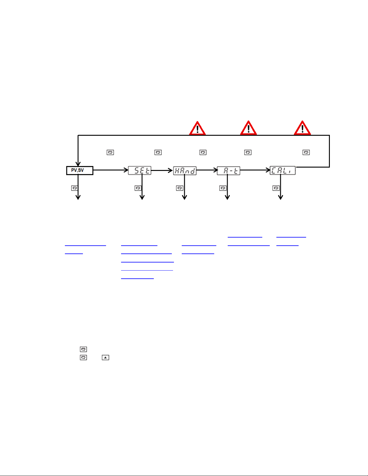
1.1 Menu Flowchart
The Menu has been divided in to 5 groups. They are as follows:
1. User Menu
2. Setup Menu
3. Manual Mode Menu
4. Auto-Tuning Mode Menu
5. Calibration Mode Menu
User Menu
Setup
Menu
5 Sec 6.2 Sec 7.4 Sec 8.6 Sec 9.8 Sec
5 Sec 5 Sec 2 Sec Min
3 Sec Max
parameter
In the User Menu,
Refer to
Section 1.1.1.1,
page 5
parameter in
the Setup Menu,
Refer to
Section 1.1.1,
Starting on Page 5.
Manual
Control
Mode, Refer to
Section 1.1.2
Page 7 & 18
Auto-Tuning
Mode, Refer to
Section 1.1.3
Page 7, 15 & 16
Calibration Mode,
Refer to
Section 2.5
Page 14
8 Sub-menu options
are available for the
setup menu.
- Basic Menu
- Output Menu
- Alarm Menu
- Event Input Menu
- User Select Menu
Press for the next parameter
Press and key to return to the previous parameter.
Page 4 of 18
Page 6
or
SET bASE
OFS1
OFS2
OFS3
INPT
UNIT
DP
INLO
INHI
SP1L
SP1H
FIL T
DISP
PB
TI
TD
RAM P
RR
RET Y
RELO
REHI
RMSP
RINL
RINH
CODE
OFST L
OFST H
CALO
CAHI
SFT
SFL1
SFL2
SFtH
*Not Applicable
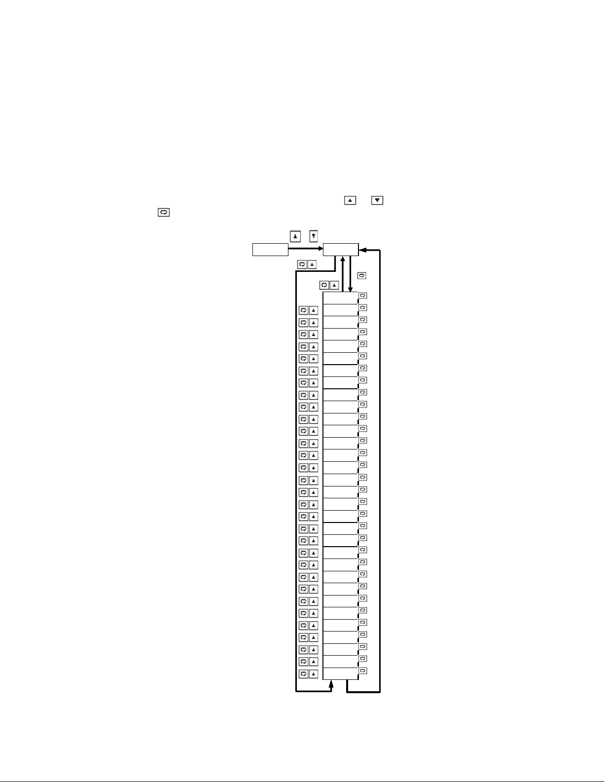
1.1.1 Setup Menu
1.1.1.1 Basic Menu (bASE)
The setup menu has been categorized in to eight categories. They are listed below.
1. Basic Menu (pg 5) *5. User Select Menu
2. Output Menu (pg. 6) *6. Communication Menu
*3. Alarm Menu *7. Current Transformer Menu
*4. Event Input Menu *8. Profile Menu (Ramp and Soak)
In the setup menu, when the upper display says “SET”, Use the or keys to get “bASE” in the lower display.
Then, use the key to cycle through the “bASE” menu parameters (Note Chart on pg. 8).
Page 5 of 18
Page 7
or
SET OUT
OUT 1
O1T Y
O1FT
O1HY
CYC1
OFST
OUT 2
O2T Y
O2FT
CYC2
CPB
DB
PL1L
PL1H
PL2L
PL2H
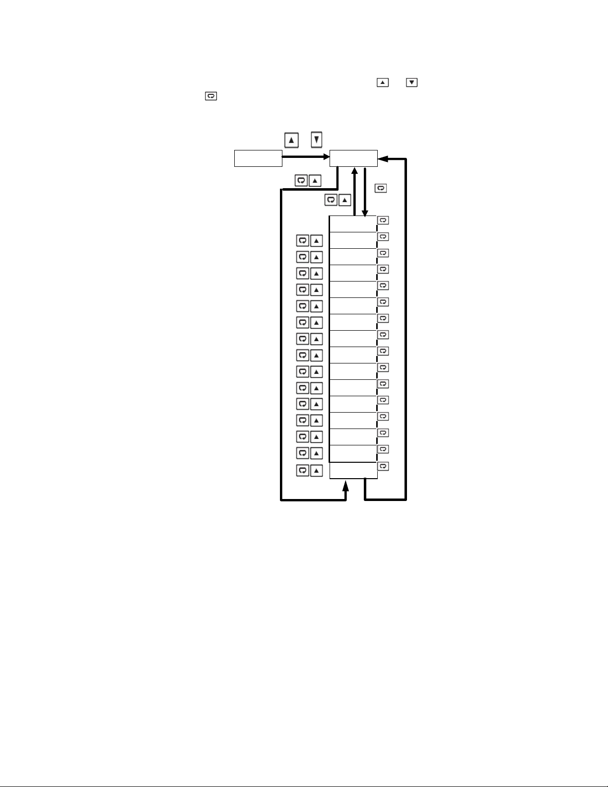
1.1.1.2 Output Menu (oUT)
In the setup menu, when the upper display says “SET”, use the or key to get “oUT” in the lower
display. Then, use the key to cycle through the “oUT” menu parameters (Note Chart on pg. 9).
Page 6 of 18
Page 8
HANd
5 Sec
M V1
M V2
FILE
Press key 5 Sec To execute the selected default program
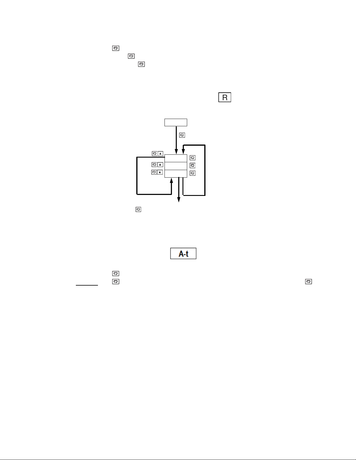
1.1.2 Manual Mode Menu – (Use for Temporary Operation if Sensor Fails)
Press and hold the “ ” key for approx. 6sec until the “HAND” parameter is shown in the upper display.
Then, press and hold the “ ” key for an additional 5 sec. until an “MANU” led starts to flash in the lower left
of the display. Then, use the “ ” key to cycle through the available options.
User is able to manually set the out output to be energized from 0-100% of the cycle time.
“Hx.xx” is used to adjust output 1.
“Cx.xx” is used to adjust output 2.
You are able to exit manual mode by pressing and holding the key.
1.1.3 Auto-Tuning Mode – (Tunes PID Parameters to Your Application)
Press and hold the “ ” key for approx. 7sec until the “A-T” parameter is shown in the upper display.
Press and hold the “ ” key for 5 seconds to activate Auto-Tuning Mode. Continue to hold the “ ” key for
an additional 3 seconds, else the display will revert to a “User Menu” parameter.
Auto-tuning allows the controller to find its own optimal control parameters (PID) by measuring the speed of
your thermal process.
Page 7 of 18
Page 9

(*Parameters that are not applicable are not shown)
Set Point 1
(Used for Output 1)
0 J_tC: J type Thermocouple
input
0 oC:°C unit
2 Pu:Process unit
0 No.dP: No decimal point
3 3-dP: 3 decimal digit
0 0: 0 second time constant
9 60: 60 second time constant
1.2 Parameter Description
Register
Address
0
8
Parameter
Notation
SP1
INPT
(See Pg. 11)
Parameter Description Range
Low: SP1L
High: SP1H
1 K_tC: K type Thermocouple
2 T_tC: T type Thermocouple
3 E_tC: E type Thermocouple
4 B_tC: B type Thermocouple
5 R_tC: R type Thermocouple
6 S_tC: S type Thermocouple
7 N_tC: N type Thermocouple
8 L_tC: L type Thermocouple
9 U_tC: U type Thermocouple
Input sensor selection
10 P_tC: P type Thermocouple
11 C_tC: C type Thermocouple
12 D_tC: D type Thermocouple
13 Pt.dN: PT100 Ω DIN curve
14 Pt.JS: PT100 Ω JIS curve
15 4-20: 4-20mA linear current input
16 0-20: 0-20mA linear current input
17 0-5V: 0-5VDC linear voltage input
18 1-5V: 1-5VDC linear voltage input
19 0-10: 0-10VDC linear voltage
Default
Value
77.0°F
0, 1 or 13
(Depends on
Model Ordered)
9
10
13
14
15
UNIT Input unit selection
DP Decimal point selection
SP1L
SP1H
Low limit of set point 1
(Span Value)
High limit of set point 1
(Span Value)
Filter damping time constant of
FILT
PV Sensor
(See Pg. 14)
1 oF:°F unit
1 1-dP: 1 decimal digit
2 2-dP: 2 decimal digit
Low: -19999
High :SP1H
Low: SP1L
High: 45536
1 0.2: 0.2 second time constant
2 0.5: 0.5 second time constant
3 1: 1 second time constant
4 2: 2 second time constant
5 5: 5 second time constant
6 10: 10 second time constant
7 20: 20 second time constant
8 30: 30 second time constant
1
0
0.0° F
1000.0°F
2
Page 8 of 18
Page 10

(*Parameters that are not applicable are not shown)
0 None: No Display
4 PRoF: display Profile Status
0 RELY: Relay output
6
: 0-10VDC linear voltage
Register
Address
16
17
18
19
20
Parameter
Notation
Parameter Description Range
DISP Secondary display selection
PB
TI
TD
Proportional band value
(See Pg. 17)
Integral time value
(See Pg. 17)
Derivative time value
(See Pg. 17)
OUT1 Output 1 function
1 MV1: Display MV1
2 MV2: Display MV2
3 tIMR: Display Dwell Time
Low: 0.0
High: 500.0°C (900.0°F)
Low: 0
High: 3600 sec
Low: 0.0
High: 360.0 sec
0 REVR: Reverse (heating) control
action
1 dIRt : Direct (cooling) control
action
Default
Value
0
10.0° C
(18.0° F)
100
25
0
21
22
23
24
26
O1TY
FACTORY
SET, DO
Output 1 signal type
NOT
CHANGE
O1FT
O1HY
Output 1 failure transfer mode
(See Pg. 15)
Output 1 ON-OFF control
hysteresis. PB=0
CYC1 Output 1 cycle time
RAMP
Ramp function selection
(See Pg. 13)
1 SSrd: Solid state relay drive
output
2 4-20: 4-20mA linear current
3 0-20: 0-20mA linear current
4 0-5V: 0-5VDC linear voltage
5 1-5V: 1-5VDC linear voltage
0-10
Select BPLS (Bumpless transfer), or
0.0 ~ 100.0 % to continue output 1
control function if the sensor fails, or
select OFF (0) or ON (1) for ON-OFF
control
Low: 0.1°C (0.2°F)
High: 50.0°C (90.0°F)
Low: 0.1
High: 90.0 sec.
0 NoNE: No Ramp Function
1 MINR: Use ⁰/minute as Ramp Rate
2 HRR: Use ⁰/hour as Ramp Rate
1
0
0.1° C
(0.2 °F)
1.0
0
Page 9 of 18
Page 11

(*Parameters that are not applicable are not shown)
Register
Address
27
61
62
94
Parameter
Notation
RR
Parameter Description Range
Ramp rate
(See Pg. 13)
PL1L Output 1 Low Power limit
PL1H Output 1 High Power limit
PASS
Password entry
(See Next Page)
Low: 0.0
High: 900.0°F
Low: 0
High:PL1H or 50%
Low: PL1L
High: 100 %
Low: 0
High: 9999
Default
Value
0
0
100
0
Page 10 of 18
Page 12
CODE Value
PASS Value
Access Rights
0
Any Value
All parameters are changeable
=1000
All parameters are changeable
≠1000
Only user menu parameters changeable
=9999
All parameters are changeable
≠9999
Only SP1 to SP7 are changeable
=CODE
All parameters are changeable
≠CODE
No parameters can be changed
2 Programming
Press and hold for 5 seconds, then release to enter the setup menu. Press and release to cycle
through the list of parameters. The upper display indicates the parameter symbol, and the lower display
indicates the value of the selected parameter.
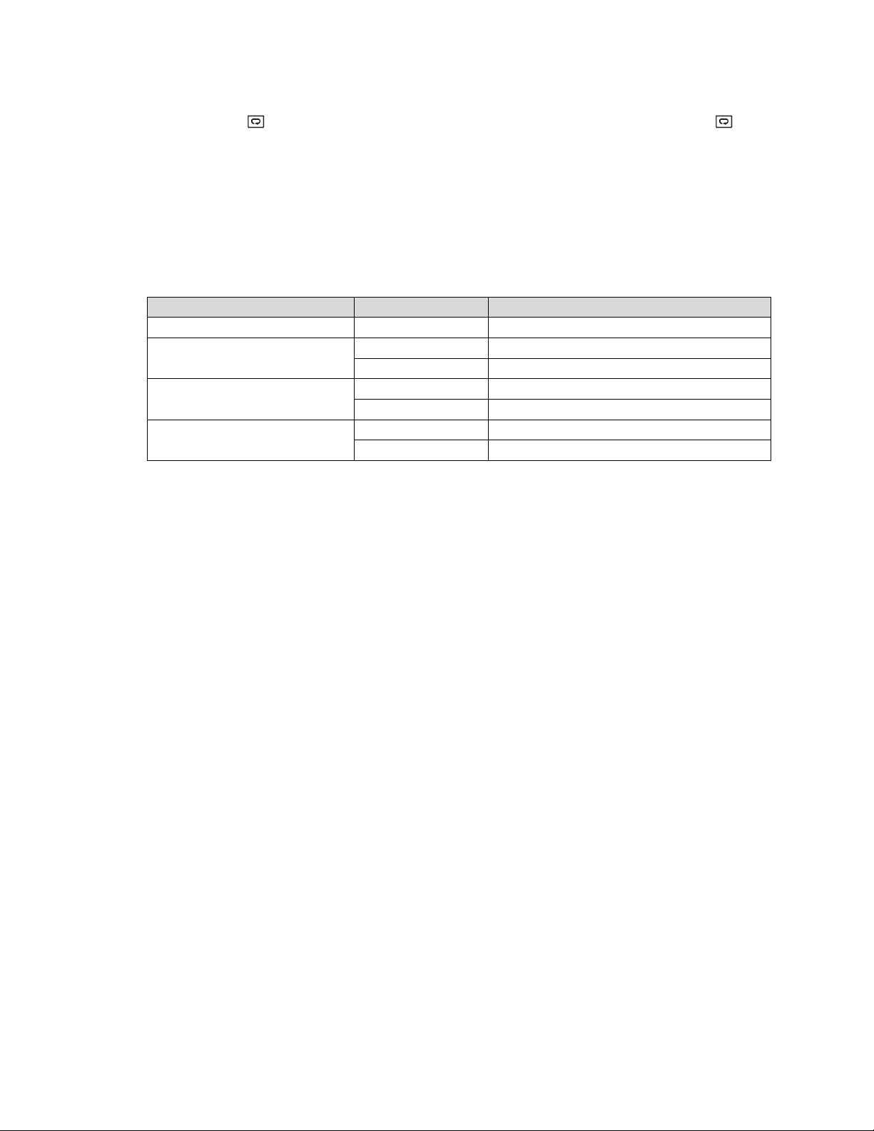
2.1 User Security
There are two parameters, PASS (password) and CODE (security code), which will control the lockout
program.
1000
9999
Others
2.2 Signal Input
INPT: Select the desired sensor type or signal type for the signal input. Factory set.
DO NOT CHANGE
UNIT: Select the desired process unit
Options: °C, °F, PU (Process unit). If the unit is neither °C nor °F, then is set to PU.
DP: Select the desired resolution (decimal points) for the process value.
2-1.User Access Rights
Page 11 of 18
Page 13
2.3 Control Output
There are 4 kinds of control modes can be configured as shown below.
2.3.1 Heat Only ON-OFF Control – (Used for Solonoids and Valves)
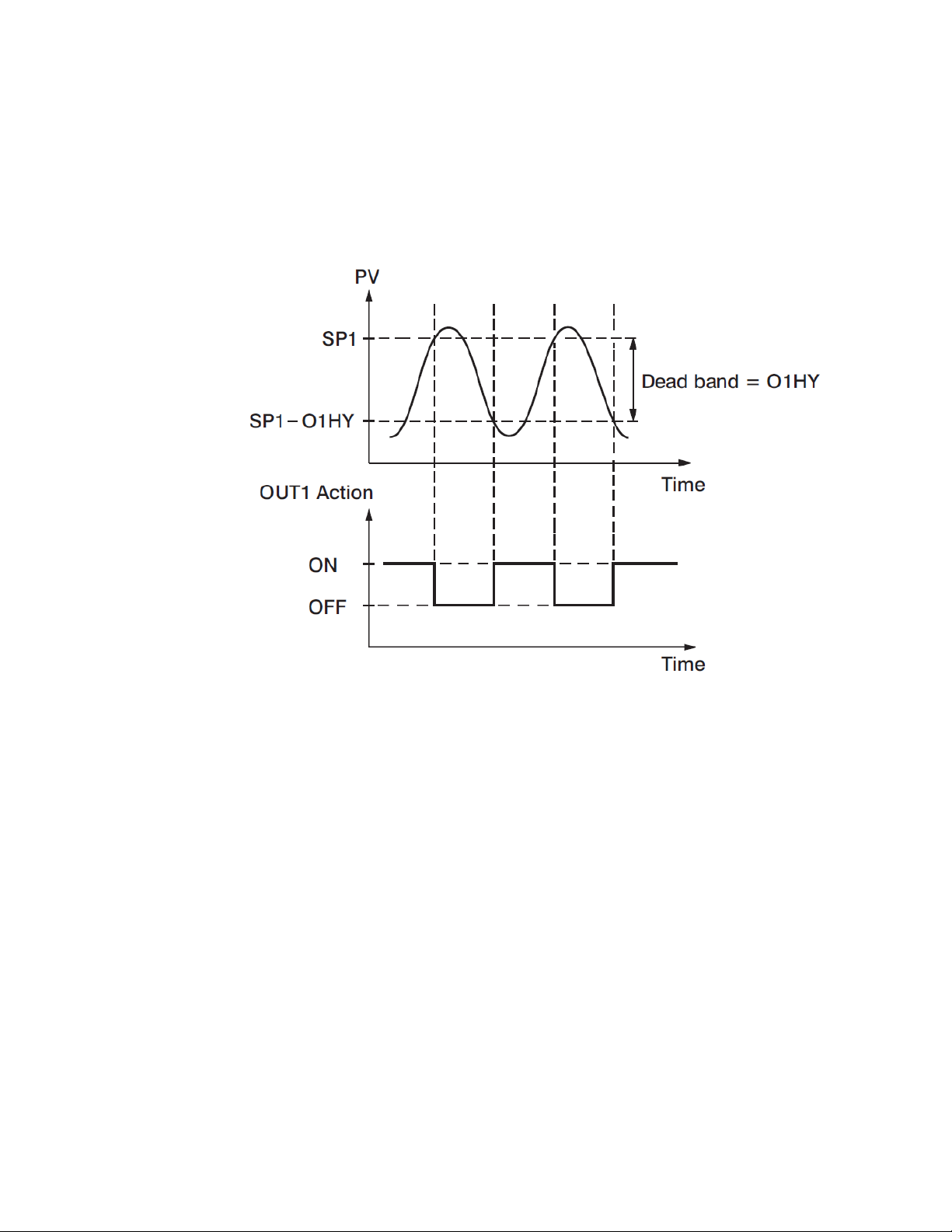
Select REVR for OUT1, Set PB to 0. O1HY is used to adjust the hysteresis for ON-OFF
control. The output 1 hysteresis (O1HY) setting is only available when PB = 0. The heat only ON-OFF
control function is shown below.
2-1.Heat Only ON-OFF Control
ON-OFF control may cause excessive process oscillations even if the hysteresis is set to the smallest value.
If ON-OFF control is used (i.e. PB = 0), TI, TD, CYC1, OFST, CYC2, CPB, DB will no longer be applicable
and will be hidden. Auto-Tuning mode and Bumpless transfer are not possible in on/off mode.
2.3.2 Heat only P or PD Control – (Used for Electric Heaters)
Select REVR for OUT1, set TI = 0, OFST is used to adjust the control offset (manual reset). If PB ≠0 then
O1HY will be hidden.
OFST Function: OFST is measured in % with a range of 0 - 100.0 %. When the process is stable, let’s say
the process value is lower than the set point by 5°F. Let’s also say that 20.0 is used for the PB setting. In
this example, 5°F is 25% of the proportional band (PB).
By increasing the OFST value by 25%, the control output will adjust itself, and the process value will
eventually coincide with the set point.
When using Proportional (P) control (TI = 0), Auto-Tuning will be unavailable. Refer to the “manual tuning"
section for the adjustment of PB and TD. Manual reset (OFST) is usually not practical because the load may
change from time to time; meaning the OFST setting would need to be constantly adjusted. PID control can
avoid this problem.
Page 12 of 18
Page 14

2.3.3 Heat only PID Control – (Default for Electric Heaters)
Select REVR for OUT1. PB and TI should not be zero. Perform Auto-Tuning for initial startup. If the control
result is not satisfactory, use manual tuning or try Auto-Tuning a second time to improve the control
performance.
2.3.4 Cool only Control
ON-OFF control, Proportional control, and PID control can be used for cooling control. Set “OUT1” to DIRT
(direct action).
NOTE: ON-OFF control may result in excessive overshoot and undershoot in the process. Proportional
control could result in a deviation of the process value from the set point. It is recommended to use PID
control for Heating or Cooling control to produce a stable process value.
When selecting parameters, all of the above parameters may not be available. The number of visible
parameters depends on the configuration of the controller.
2.4 Ramp
The ramping function is performed during power up or any time the set point is changed. Choose “MINR”
(ramp in minutes) or “HRR” (ramp in hours) for the “RAMP” setting, and the controller will perform the
ramping function. The ramp rate is programmed by adjusting the “RR” setting. The ramping function is
disabled whenever the controller enters Failure mode, Manual control mode, Auto-Tuning mode or
Calibration mode.
2.4.1 Ramping Example without Dwell Timer
Set the “RAMP” setting to “MINR” to ramp in minutes.
Set the ramp rate (RR) to 10.
The starting temperature is 30°C.
The setpoint is initially set to 200°C.
After the process warms up, the user changed the setpoint to 100°C after 30 minutes.
After power up, the process will behave as shown below.
2-2.Ramp Function
Page 13 of 18
Page 15
Note: When the ramp function is used, the lower display will show the current ramping value. However, it will revert to
show the set point value as soon as the up or down key is touched for adjustment. The ramp rate is initiated at power
on and/or whenever the Set point is changed. Setting the “RR” setting to zero means no ramping function is used.
2.5 User Calibration
Each unit is calibrated in the factory before shipment. The user can still modify the calibration in the field.
The basic calibration of the controller is highly stable and set for life. User calibration allows the user to offset
the permanent factory calibration in order to:
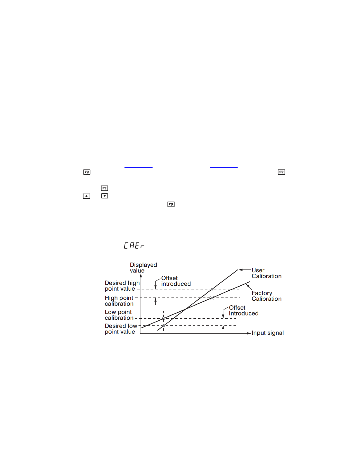
There are two parameters: Offset Low (OFTL) and Offset High (OFTH) for adjustment to correct an error in
the process value.
There are two parameters for the sensor input. These two signal values are CALO and CAHI. The input
signal low and high values are to be entered in the CALO and CAHI parameters respectively.
Refer to section 1.6 for key operation and section 1.7 for the operation flowchart. Press and
hold the key until the setup Menu page is obtained. Then, press and release the key to navigate to
the calibration low parameter OFTL. Send your low signal to the sensor input of the controller, then press
and release the key. If the process value (the upper display) is different from the input signal, the user
can use and keys to change the OFTL value (the lower display) until the process value is equal to the
value the user needs. Press and hold the key for 5 seconds to complete the low point calibration (the
display should blink once). The same procedure is applied for high scale calibration.
As shown below, the two points OFTL and OFTH construct a straight line. For the purpose
of accuracy, it is best to calibrate with the two points as far apart as possible. After the user calibration is
complete, the input type will be stored in the memory. If the input type is changed, a calibration error will
v Calibrate the controller to meet a user reference standard.
v Match the calibration of the controller to that of a particular transducer or sensor input.
v Calibrate the controller to suit the characteristics of a particular installation.
v Remove long term drift in the factory set calibration.
occur and an error code is displayed.
2-3.Two Point User Calibration
2.6 Digital Filter
In certain applications the process value is too unstable to be read. To improve this, a
programmable low pass filter incorporated in the controller can be used. This is a first order filter with a time
constant specified by the FILT parameter. A value of 0.5 seconds is used as a factory default. Adjust FILT
to change the time constant from 0 to 60 seconds. 0 seconds represents no filter applied to the input signal.
The filter is characterized by the following diagram.
Page 14 of 18
Page 16
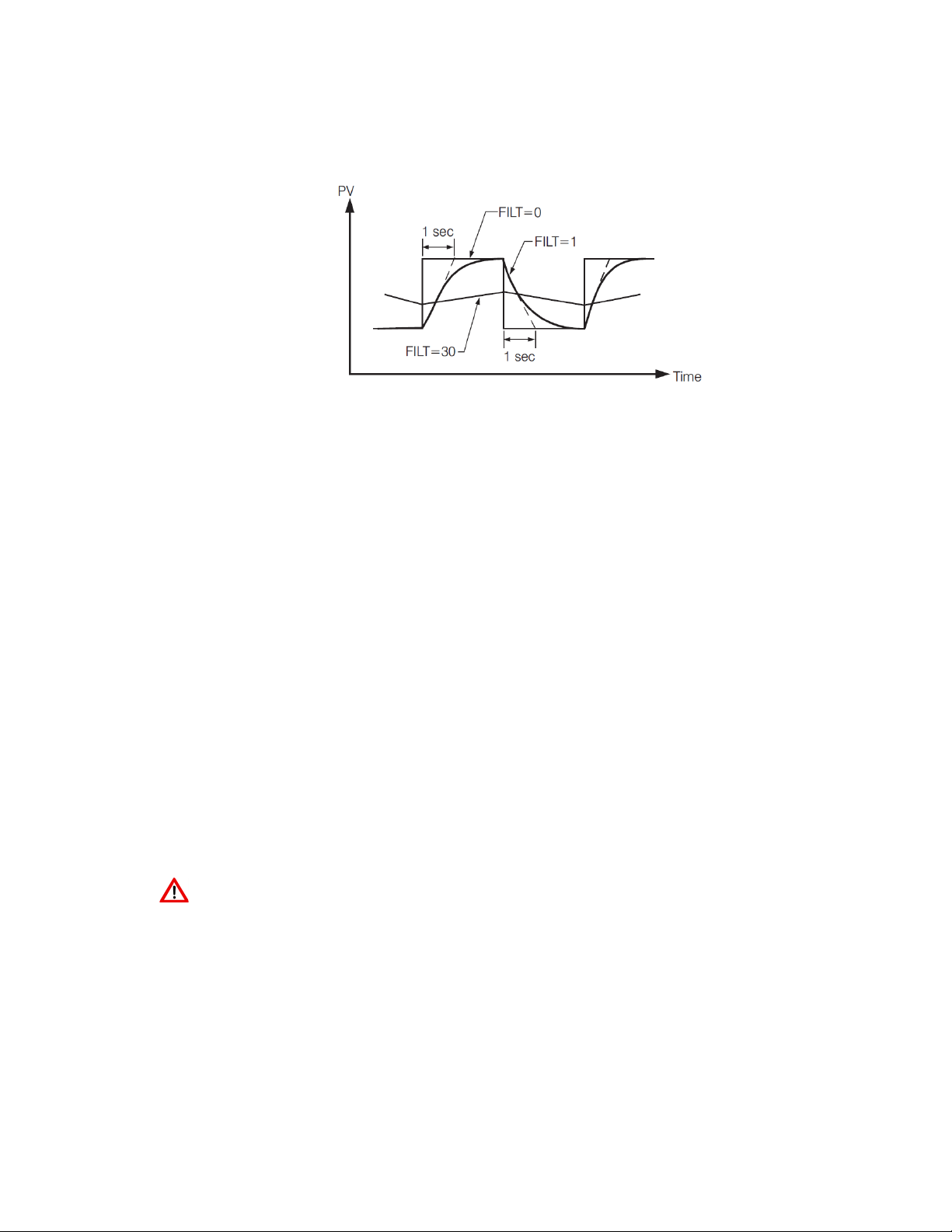
Note: The Filter is available only for the process value (PV), and is performed for the displayed value only.
The controller is designed to use an unfiltered signal for control even when a filter is applied. If a lagged
(filtered) signal is used for control; it may produce an unstable process.
2.7 Failure Transfer
The controller will enter failure mode if one of the following conditions occurs:
1. An SBER error occurs due to an input sensor break, an input current below 1mA for 4-20mA, or an
input voltage below 0.25V for 1-5 V.
2. An ADER error occurs due to the A-D converter failing.
Output 1 and Output 2 will perform the failure transfer (O1.ft & O2.ft) function as the controller enters failure mode.
2-4.Filter Characteristics
2.7.1 Output 1 Failure Transfer
If Output 1 Failure Transfer is activated, it will perform as follows:
1. If output 1 is configured as proportional control (PB≠0), and BPLS is selected for O1FT, then output
1 will perform a Bumpless transfer. After that, the previous average value of of the output will be
used for controlling output 1.
2. If output 1 is configured as proportional control (PB≠0), and a value of 0 to 100.0 % is set for O1FT,
then output 1 will perform failure transfer. After that the value of O1FT will be used for controlling
output 1.
3. If output 1 is configured as ON-OFF control (PB=0), then output 1 will transfer to an off state if OFF
is set for O1FT, or it will transfer to an on state if ON is set for O1FT.
2.8 Auto-Tuning
The Auto-Tuning process will be performed at the set point (SP1). The process will oscillate around the
set point during the tuning process. Set a set point to a lower value if overshooting beyond the normal
process value will cause damage. It is usually best to perform Auto-Tuning at the Set point the machine is
expected to be operated at, with the process running normally (i.e. material in the oven, etc.)
Auto-Tuning is generally applied in the following cases:
v Initial setup for a new process
v The set point is changed substantially from the previous Set point when Auto-Tuning was performed.
v The control result is unsatisfactory
Page 15 of 18
Page 17

2.8.1 Auto-Tuning Operation Steps
1. The system is set up to run under real-world conditions.
2. “PB and “TI” settings should not be set to zero.
3. The LOCK parameter should be set to NONE.
4. Set the set point to a normal operating value, or a lower value if overshooting beyond the
normal process value will cause damage.
5. Press and hold the key until appears on the upper display. Continue to hold the
“ ” key for an additional 3 seconds, else the display will revert to a “User Menu”
parameter.
6. Press and hold the key until the TUNE indicator begins to flash.
7. The Auto-Tuning process has begun.
NOTE:
During Auto-Tuning, the output will stay on until the Process Value reaches the setpoint. This is likely to
cause the temperature to exceed the setpoint.
Then, the output will remain off until the process value falls below the setpoint.
This will occur at least two times while the controller “learns” how to control your process.
Procedures:
Auto-Tuning can be applied either as the process is warming up (Cold Start) or as the
process has been in steady state (Warm Start). After the Auto-Tuning process is completed, the TUNE
indicator will stop flashing and the unit will revert to PID control by using its new PID values. The PID values
obtained are stored in nonvolatile memory.
2.8.2 Auto-Tuning Error
If Auto-Tuning fails, an ATER message will appear on the upper display in any of the following
cases.
v If PB exceeds 9000 (9000 PU, 900.0°F or 500.0°C)
v If TI exceeds 1000 seconds
v If the set point is changed during the Auto-Tuning process
2.8.3 Solution for an Auto-Tuning Error
1. Try Auto-Tuning once again.
2. Avoid changing the set point value during the Auto-Tuning process.
3. Ensure PB and TI are not set to zero.
4. Use manual tuning.
5. Touch RESET key to reset the message.
Page 16 of 18
Page 18
ADJUSTMENT SEQUENCE
SYMPTOM
SOLUTION
Slow Response
Decrease PB
High overshoot or Oscillations
Increase PB
Slow Response
Decrease TI
Instability or Oscillations
Increase TI
Slow Response or Oscillations
Decrease TD
High Overshoot
Increase TD
2.9 Manual Tuning
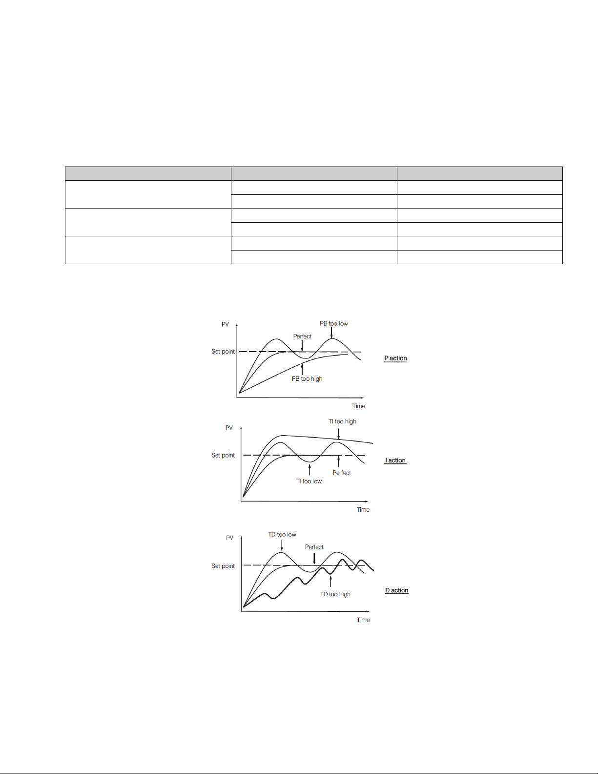
In certain applications, using Auto-Tuning may be inadequate for the control requirement, or, the process
moves too slowly to Auto-tune accurately.
If this is the case, the user can try manual tuning.
If the control performance by using Auto-Tuning is still unsatisfactory, the following guidelines can be applied
for further adjustment of PID values.
Proportional Band ( PB )
Integral Time ( TI )
Derivative Time ( TD )
2-2.PID Parameter Adjustment Guide
2-5. Effects of PID Adjustment
Page 17 of 18
Page 19

2.10 Manual Control
To enable manual control, ensure the LOCK parameter is set to NONE.
Press and hold until (Hand Control) appears on the display. Press and hold until
the “MANU” indicator begins to flash. The lower display will show .
Indicates the output control variable for output 1, and indicates the control variable for
output 2. The user can use the up-down keys to adjust the percentage values for the heating or cooling
output. This % value is based on the CYC1 and CYC2 settings, where the associated output will stay on for
the % of time the CYC1 & CYC2 values are set for.
Example: If CYC1 is set to 20seconds, and the controller is set to “H50.0”, the output will be on for
10seconds, then turn off for 10 seconds.
The controller performs open loop control and ignores the input sensor as long as it stays in manual control
mode
2.10.1 Exit Manual Control
Pressing the key will revert the controller to its normal display mode.
2.11 Setting Controller to Factory Default
The controller’s parameters can be loaded with default values listed in the parameter description table . In
certain situation it is desirable to retain these values after the parameters values has been changed. The
below procedure to be followed to reload the default values.
1. Ensure the LOCK parameter is set to NONE.
2. Press and hold until (Hand Control) appears on the display.
3. Press and release the key to cycle through the manual mode menu to reach “FILE”.
4. Press and hold for 5 seconds or until the upper display FILE flash for a moment.
Page 18 of 18
Page 20

Custom Manufacturer Since 1972
ELECTRIC HEATING ELEMENTS • TEMPERATURE CONTROLS • SENSORS • PROCESS HEATING SYSTEMS
HEAT THINGS UP!
With Thousands of Design Variations
We Make Everything You Need.
Band Heaters
Cast-In Heaters
Radiant Heaters
Flexible Heaters
Process Heaters
Temperature Control
Cartridge Heaters
Coil & Cable Heaters
Strip Heaters
Tubular Heaters
Instrumentation
Temperature Sensors
607 N. Central Avenue Wood Dale, IL 60191-1452 USA
P: 630-350-2252 Toll Free: 800-323-6859
F: 630-350-0232 E: [email protected]
© Copyright 2019 TEHC. All Rights Reserved
www.tempco.com
 Loading...