

Page 1

Installation & Operating Manual for
Tempco’s TEC95040 Digital Wood
Pellet BBQ Grill Controller
Manual TEC95040 Revision 9/2012
TEMPCO Electric Heater Corporation
607 N. Central Ave. • Wood Dale, IL 60191
Tel: 630-350-2252 • Toll Free: 800-323-6859
Fax: 630-350-0232 • E-mail: [email protected]
Web: www.tempco.com
Page 2

This manual contains complete information about the
Tempco TEC95040 Digital Wood Pellet BBQ Grill
Controller including Installation and Operation.
Page 3

1
Thank you for purchasing Tempco’s
TEC95040 Digital Wood Pellet BBQ
Grill Controller.
The TEC95040 can be used as a
replacement for the original control
or as an upgrade for your existing
control.
The TEC95040 is compatible with the
following wood pellet grill companies:
Traeger Company
Royall
BLAZ’N
IPT Sink
Introduction
TEC95040 Design Features
• Temperature Display: Large 3 digit
• Temperature Setpoints: 9 setpoints 180° to 450°F
• Smoke Setting: Adjustable pellet feed rate
• Automatic pellet ignition cycle
• Power: 120VAC
• Fuse: 3A/250VAC, fast blow, 10mm long
• Spare fuse attached to fuseholder on PCB
• 2-pin connectors for:
Power Input
Output: Auger motor
Output: Ignitor/Cartridge heater
Output: Ventilation/Draft fan
• 2 Terminal, screw clamp wiring block for the
RTD Temperature Sensor
Page 4
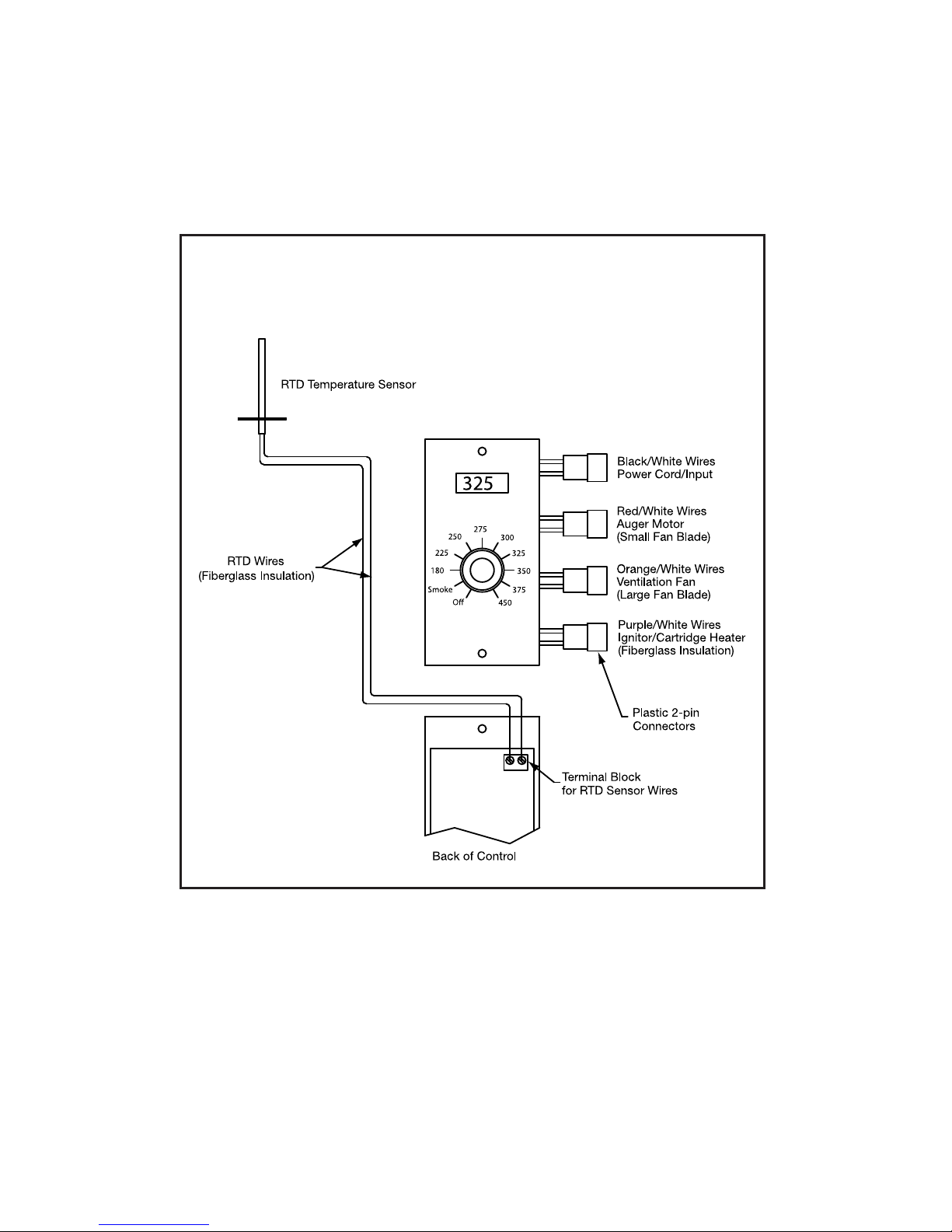
Installation
General Wiring Diagram
2
Page 5

3
Installation
WARNING: Verify that the controller’s Selector Switch is turned to the
OFF position and the line cord plug is disconnected from the outlet, before
removing or installing the new
Wood Pellet BBQ Grill Controller.
When the dial is turned to the OFF position, High Voltage Electricity is still
present on the control.
Failure to heed this warning could result in bodily harm.
Removing the Current Controller
1. Make sure the grill is unplugged from the outlet before proceeding.
2. Gain access to the controller wiring harness below the pellet hopper
.
Sometimes, there is a protective panel below the hopper. Remove and set
aside.
3. Disconnect all four 2-pin plastic electrical connectors by pulling them apart.
4. Remove the controller from the grill by unscrewing the two faceplate screws.
Save the screws for mounting your new
TEC95040 Controller.
5. Gently pull the control out of the panel cutout, being careful of the Printed
Circuit Board and wiring harness.
6. If the existing controller is a digital model, the RTD temperature sensor
wiring must be disconnected from the control board.
Using a very small flat blade screwdriver, remove the RTD Temperature
Sensor wires from the terminal block
at the upper right of the Printed
Circuit Board.
Page 6
4
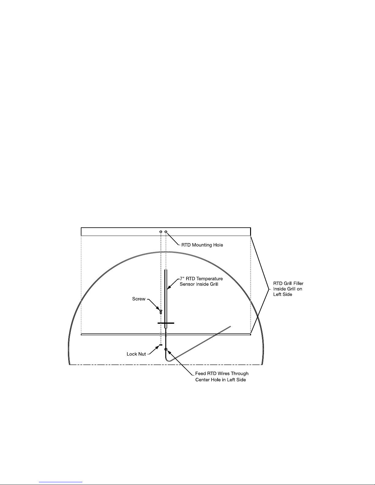
Installing the RTD Temperature Sensor
It is recommended when replacing an existing Digital Controller, the RTD
(Resistive Temperature Detector) Temperature Sensor also be replaced to avoid
further potential problems.
1. Open the grill cover and remove the Porcelain Grill and Drip Pan to provide
access to the left side of the grill where the RTD Temp Sensor is located.
2. If the existing Temp Sensor is being replaced, remove the screw and nut and
carefully pull out the sensor and wiring. Save the screw and nut.
3. For a new installation, locate the two pre-punched RTD Temperature Sensor
mounting holes on the left side of the grill. Refer to the drawing.
4. Feed the wires carefully thru the hole, followed by the sensor stem so it’s
standing upright.
5. Using an 8-32 or 10-32 x 1/2” screw and nut (not supplied), secure the sensor.
6. Run the sensor lead wires down between the pellet hopper and the grill and
up and thru the controller cutout.
Page 7
5
6. Re-install the access panel under the Pellet Hopper if it was removed.
Replace the Porcelain Grill and Drip Pan.
Installing the TEC95040
Digital Wood Pellet BBQ Grill Controller
1. Turn the controller over and locate
the 2-pin terminal block in the
upper right, as shown in the photo.
2. Outside the control cutout, using a
very small flat blade screwdriver,
connect the RTD temp sensor wires.
Polarity does not matter.
3. Feed the wire harness and connected RTD wires back thru the panel
cutout, being careful with the
Printed Circuit board.
4. Using the previously saved mounting screws, secure the controller.
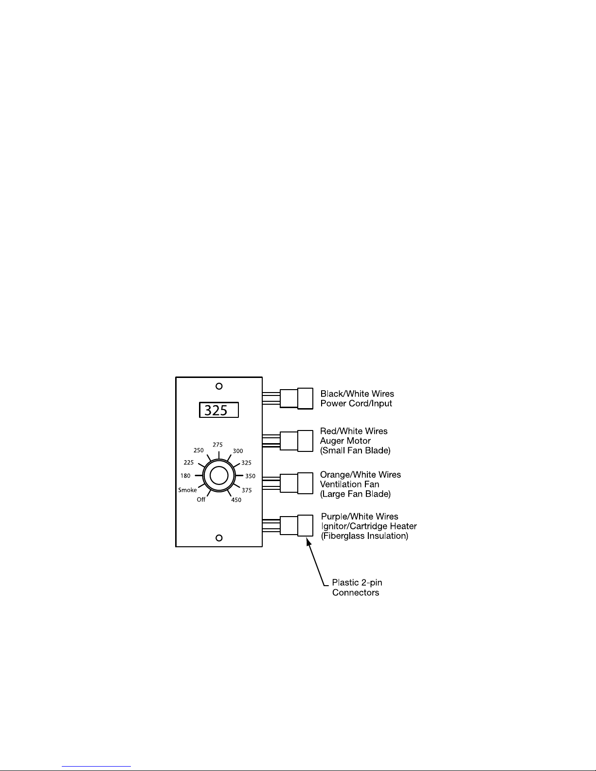
5. Working under the pellet hopper, plug-in all four 2-pin wiring connectors as
follows, refer to the wire diagram.
Page 8

6
Operation
1. Verify the Selector Switch is in the OFF position and plug the grill into a
properly grounded electrical output.
2. Turn the Selector Switch to Smoke or any of the nine temperature settings.
3. The ventilation/draft fan and the auger pellet feed motor turns on.
4. The ignitor/cartridge heater will turn on to ignite the wood pellets in the fire
pot. After four minutes, the ignitor/cartridge heater will turn off.
5. Set the Selector Switch to your cook temperature and enjoy.
Adjusting the Smoke Pellet Feed Rate
Sometimes due to environmental conditions or personal tastes, the Smoke pellet
feed rate requires adjustment to raise or lower the temperature at the Smoke setting.
1. The small selector switch on the PCB, adjusts the Smoke pellet feed rate.
2. The factory default is position 2. It is
recommended that the setting not be set
to over 5.
3. Smoke Selector Switch Setting for Pellet Feed Rate.
Switch position 0: Auger on for 15 seconds, off for 45 seconds
Switch position 1: Auger on for 15 seconds, off for 55 seconds
Switch position 2: Auger on for 15 seconds, off for 65 seconds
Switch position 3: Auger on for 15 seconds, off for 75 seconds
Switch position 4: Auger on for 15 seconds, off for 85 seconds
Switch position 5: Auger on for 15 seconds, off for 95 seconds
4. Be careful that the switch position selected feeds enough pellets, so that
the f
ire does not go out.
© Copyright 2012 TEHC. All Rights Reserved.
 Loading...