

Tempco TEC-9300 Instruction Manual

Instruction Manual
TEC-9300
Self-Tune Fuzzy / PID Process
Temperature Controller
Serving Industry Since 1972
Agency Approvals: RoHS
TEMPCO Electric Heater Corporation
607 N. Central Avenue • Wood Dale, IL 60191-1452 USA
Tel: 630-350-2252 • Toll Free: 800-323-6859
Fax: 630-350-0232 • E-mail: info@tempco.com
Web: www.tempco.com
Manual TEC-9300 Revision 9/2016

NOTES

Warning Symbol
This symbol calls attention to an operating procedure, practice, or
the like which, if not correctly performed or adhered to, could
result in personal injury or damage to or destruction of part or all
of the product and system. Do not proceed beyond a warning symbol until the indicated conditions are fully understood and met.
Using the Manual
Installers . . . . . . . . . . . . . . . . . . . . . . . . . . . Read Chapters 1, 2
Basic Function User . . . . . . . . . . . . . . . . Read Chapters 1, 3, 5
Enhanced Function User . . . . . . . . . . Read Chapters 1, 3, 4, 5
System Designer . . . . . . . . . . . . . . . . . . . . . Read All Chapters
Expert User . . . . . . . . . . . . . . . . . . . . . . . . . . . . . . Read Page 8
CONTENTS
Chapter 1 - Overview
1-1 Features . . . . . . . . . . . . . . . . . . . . . . . . . . . . . . . . . . . . 1
1-2 Hardware Code . . . . . . . . . . . . . . . . . . . . . . . . . . . . . . . 2
1-3 Programming Port and DIP Switch . . . . . . . . . . . . . . . 3
1-4 Keys and Displays . . . . . . . . . . . . . . . . . . . . . . . . . . . . 4
1-5 Menu Overview . . . . . . . . . . . . . . . . . . . . . . . . . . . . . . 6
1-6 System Modes . . . . . . . . . . . . . . . . . . . . . . . . . . . . . . . 7
1-7 Parameter Description . . . . . . . . . . . . . . . . . . . . . . . . . 8
Page No
Chapter 2 - Installation
2-1 Unpacking . . . . . . . . . . . . . . . . . . . . . . . . . . . . . . . . . . 15
2-2 Mounting . . . . . . . . . . . . . . . . . . . . . . . . . . . . . . . . . . . 15
2-3 Wiring Precautions . . . . . . . . . . . . . . . . . . . . . . . . . . . 15
2-4 Power Wiring . . . . . . . . . . . . . . . . . . . . . . . . . . . . . . . . 16
2-5 Sensor Installation Guidelines . . . . . . . . . . . . . . . . . . . 16
2-6 Thermocouple Input Wiring . . . . . . . . . . . . . . . . . . . . 16
2-7 RTD Input Wiring . . . . . . . . . . . . . . . . . . . . . . . . . . . . 17
2-8 Linear DC Input Wiring . . . . . . . . . . . . . . . . . . . . . . . 17
2-9 CT/Heater Current Input Wiring . . . . . . . . . . . . . . . . . 18
2-10 Event Input wiring . . . . . . . . . . . . . . . . . . . . . . . . . . . 19
2-11 Output 1 Wiring . . . . . . . . . . . . . . . . . . . . . . . . . . . . . 20
2-12 Output 2 Wiring . . . . . . . . . . . . . . . . . . . . . . . . . . . . . 21
2-13 Alarm 1 Wiring . . . . . . . . . . . . . . . . . . . . . . . . . . . . . 22
2-14 Alarm 2 Wiring . . . . . . . . . . . . . . . . . . . . . . . . . . . . . 22
2-15 RS-485 . . . . . . . . . . . . . . . . . . . . . . . . . . . . . . . . . . . . 23
2-16 RS-232 . . . . . . . . . . . . . . . . . . . . . . . . . . . . . . . . . . . . 24
2-17 Analog Retransmission . . . . . . . . . . . . . . . . . . . . . . . 24
Chapter 3 - Programming Basic Functions
3-1 Input 1 . . . . . . . . . . . . . . . . . . . . . . . . . . . . . . . . . . . . . 25
3-2 OUT1 and OUT2 Types . . . . . . . . . . . . . . . . . . . . . . . 26
3-3 Configuring User Menu . . . . . . . . . . . . . . . . . . . . . . . . 26
3-4 Heat Only Control . . . . . . . . . . . . . . . . . . . . . . . . . . . . 26
3-5 Cool Only Control . . . . . . . . . . . . . . . . . . . . . . . . . . . . 27
3-6 Heat-Cool Control . . . . . . . . . . . . . . . . . . . . . . . . . . . . 28
3-7 Dwell Timer . . . . . . . . . . . . . . . . . . . . . . . . . . . . . . . . . 29
3-8 Process Alarms . . . . . . . . . . . . . . . . . . . . . . . . . . . . . . 30
3-9 Deviation Alarms . . . . . . . . . . . . . . . . . . . . . . . . . . . . . 31
3-10 Deviation Band Alarms . . . . . . . . . . . . . . . . . . . . . . . 32
3-11 Heater Break Alarm . . . . . . . . . . . . . . . . . . . . . . . . . . 33
3-12 Loop Break Alarm . . . . . . . . . . . . . . . . . . . . . . . . . . . 33
3-13 Sensor Break Alarm . . . . . . . . . . . . . . . . . . . . . . . . . 34
3-14 SP1 Range . . . . . . . . . . . . . . . . . . . . . . . . . . . . . . . . . 34
3-15 PV1 Shift . . . . . . . . . . . . . . . . . . . . . . . . . . . . . . . . . . 34
3-16 Failure Transfer . . . . . . . . . . . . . . . . . . . . . . . . . . . . . 35
3-17 Bumpless Transfer . . . . . . . . . . . . . . . . . . . . . . . . . . . 36
3-18 Self-tuning . . . . . . . . . . . . . . . . . . . . . . . . . . . . . . . . . 36
3-19 Auto-tuning . . . . . . . . . . . . . . . . . . . . . . . . . . . . . . . . 37
3-20 Manual Tuning . . . . . . . . . . . . . . . . . . . . . . . . . . . . . 38
3-21 Signal Conditioner DC Power Supply . . . . . . . . . . . 39
3-22 Manual Control. . . . . . . . . . . . . . . . . . . . . . . . . . . . . . 39
3-23 Display Mode . . . . . . . . . . . . . . . . . . . . . . . . . . . . . . 40
3-24 Heater Current Monitoring . . . . . . . . . . . . . . . . . . . . 40
3-25 Reload Default Values . . . . . . . . . . . . . . . . . . . . . . . . 40
NOTE:
It is strongly recommended that a process should incorporate a LIMIT CONTROL like TEC-910 which will shut
down the equipment at a preset process condition in order to
preclude possible damage to products or system.
Information in this user’s manual is subject to change without
notice.
Copyright © 2016, Tempco Electric Heater Corporation, all
rights reserved. No part of this publication may be reproduced,
transmitted, transcribed or stored in a retrieval system, or translated into any language in any form by any means without the
written permission of Tempco Electric Heater Corporation.
CONTENTS
Page No
Chapter 4 - Full Function Programming
4-1 Event Input . . . . . . . . . . . . . . . . . . . . . . . . . . . . . . . . . 41
4-2 Second Set Point . . . . . . . . . . . . . . . . . . . . . . . . . . . . . 41
4-3 Second PID Set . . . . . . . . . . . . . . . . . . . . . . . . . . . . . . 42
4-4 Ramp and Dwell . . . . . . . . . . . . . . . . . . . . . . . . . . . . . 42
4-5 Remote Set Point . . . . . . . . . . . . . . . . . . . . . . . . . . . . . 43
4-6 Differential Control . . . . . . . . . . . . . . . . . . . . . . . . . . . 43
4-7 Output Power Limits . . . . . . . . . . . . . . . . . . . . . . . . . . 44
4-8 Data Communication . . . . . . . . . . . . . . . . . . . . . . . . . . 44
4-9 Analog Retransmission . . . . . . . . . . . . . . . . . . . . . . . . 45
4-10 Digital Filter . . . . . . . . . . . . . . . . . . . . . . . . . . . . . . . 45
4-11 Sleep Mode . . . . . . . . . . . . . . . . . . . . . . . . . . . . . . . . 45
4-12 Pump Control . . . . . . . . . . . . . . . . . . . . . . . . . . . . . . 46
4-13 Remote Lockout . . . . . . . . . . . . . . . . . . . . . . . . . . . . 46
Chapter 5 - Applications
5-1 Pump/Pressure Control . . . . . . . . . . . . . . . . . . . . . . . . 47
5-2 Variable Period Full Wave SSR (VPFW SSR) . . . . . . 47
5-3 Heat Only Control . . . . . . . . . . . . . . . . . . . . . . . . . . . . 48
5-4 Cool Only Control . . . . . . . . . . . . . . . . . . . . . . . . . . . . 49
5-5 Heat-Cool Control . . . . . . . . . . . . . . . . . . . . . . . . . . . . 49
5-6 Ramp and Dwell . . . . . . . . . . . . . . . . . . . . . . . . . . . . . 50
5-7 Remote Set Point . . . . . . . . . . . . . . . . . . . . . . . . . . . . . 51
5-8 Differential Control . . . . . . . . . . . . . . . . . . . . . . . . . . . 51
5-9 Dual Set Point/PID . . . . . . . . . . . . . . . . . . . . . . . . . . . 52
5-10 RS-485 . . . . . . . . . . . . . . . . . . . . . . . . . . . . . . . . . . . . 53
5-11 RS-232 . . . . . . . . . . . . . . . . . . . . . . . . . . . . . . . . . . . . 54
5-12 Retransmit . . . . . . . . . . . . . . . . . . . . . . . . . . . . . . . . . 54
Chapter 6 - Calibration . . . . . . . . . . . . . . . . . . . . 55
Chapter 7 - Error Codes and
Troubleshooting
. . . . . . . . . . . . . . 57
Chapter 8 - Specifications. . . . . . . . . . . . . . . . . 61
Chapter 9 - Modbus Communications . . . 63
Appendix
A-1 Menu Existence Conditions . . . . . . . . . . . . . . . . . . . . 77
A-2 Factory Menu Description . . . . . . . . . . . . . . . . . . . . . 80
A-3 Glossary . . . . . . . . . . . . . . . . . . . . . . . . . . . . . . . . . . . 81
A-4 Memo. . . . . . . . . . . . . . . . . . . . . . . . . . . . . . . . . . . . . . 85
A-5 Warranty . . . . . . . . . . . . . . . . . . . . . . . . . . . . . . . . . . . 87

NOTES
Chapter 1 Overview
__+_
+
++++
+
Figure 1.1
Fuzzy PID System Block
PID
+ FUZZY CONTROL
1–1 Features
** High accuracy 18-bit input
A–D
** High accuracy 15-bit out-
put D–A
** Fast input sample rate (5
times/second)
** Two function complexity
levels
** User menu configurable
** Pump control
* Fuzzy plus PID micro-
** Unique * Valuable
* Automatic programming
* Differential control
* Auto-tune function
* Self-tune function
* Sleep mode function
* “Soft-start” ramp and dwell
timer
* Programmable inputs (ther-
mocouple, RTD, mA, VDC)
* Analog input for remote set
point and CT
processor-based control
TEC-9300 Fuzzy Logic plus PID microprocessor-based controller incorporates a bright, easy to read, 4-digit LED display
which indicates the process value. Fuzzy Logic technology
enables a process to reach a predetermined set point in the shortest time, with the minimum of overshoot during power-up or
external load disturbance. The units are housed in a 1/16 DIN
case, measuring 48mm x 48mm with 75mm behind-panel depth.
The units feature three touch keys to select the various control
and input parameters. Using a unique function, you can put up to
five parameters at the front of the user menu by using SEL1 to
SEL5 found in the setup menu. This is particularly useful to
OEM’s as it is easy to configure the menu to suit the specific
application.
TEC-9300 is powered by 11–26VAC/VDC or 90–264VAC
supply, incorporating a 2 amp control relay output and dual 2 amp
alarm relay outputs as standard with a second alarm that can be
configured in the second output for cooling purposes or as a dwell
timer. Alternative output options include SSR drive, triac, 4–
20mA and 0–10 volts. TEC-9300 is fully programmable for
PT100, thermocouple types J, K, T, E, B, R, S, N, L, 0–20mA, 4–
20mA, and voltage signal input, with no need to modify the unit.
The input signals are digitized by using an 18-bit A to D converter. Its fast sampling rate allows the TEC-9300 to control fast
processes such as pressure and flow.
Self-tuning can be used to optimize the control parameters as
soon as undesired control results are observed. Unlike auto-tuning, self-tuning will produce less disturbance to the process during tuning, and can be used at any time.
Digital communications formats RS-485, RS-232 or 4–20mA
retransmission are available as an additional option. These
options allow the TEC-9300 to be integrated with supervisory
control systems and software, or alternatively to drive remote displays, chart recorders, or data loggers.
* Event input for changing
function and set point
* Programmable digital filter
* Hardware lockout and
remote lockout protection
* Loop break alarm
* Heater break alarm
* Sensor break alarm and
bumpless transfer
* Analog retransmission
* Signal conditioner DC
power supply
* A wide variety of output
modules available
* Safety UL/CSA/IEC1010–1
* EMC/CE EN61326
* Front panel sealed to NEMA
4X and IP65
* RS-485, RS-232 communi-
cation
Two different methods can be used to program the TEC-9300.
1. Use the keys on the front panel to program the unit manually;
2. Use a PC with setup software to program the unit via the RS485 or RS-232 COMM port.
PID control has been used and has proven to be an efficient
controlling method by many industries, yet PID has difficulty
dealing with some sophisticated systems such as second and
higher order systems, long time-lag systems, during set point
change and/or load disturbance circumstances, etc. The PID principle is based on a mathematical model which is obtained by tuning the process. Unfortunately, many systems are too complex to
describe precisely in numerical terms. In addition, these systems
may be variable from time to time. In order to overcome the
imperfections of PID control, Fuzzy Technology was introduced.
What is Fuzzy Control? It works like a good driver. Under different speeds and circumstances, he can control a car well based on
previous experience, and does not require knowledge of the kinetic theory of motion. Fuzzy Logic is a linguistic control which is
different from the numerical PID control. It controls the system
by experience and does not need to simulate the system precisely
as a PID controller would.
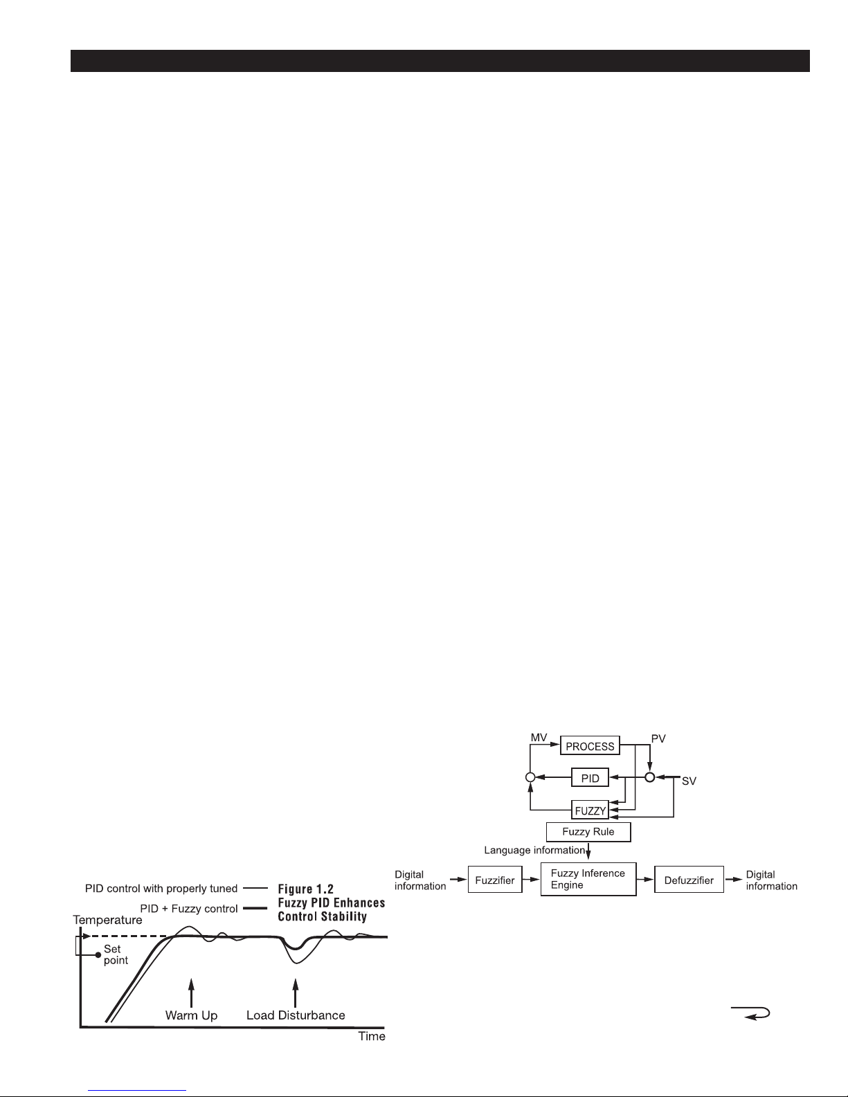
The function of Fuzzy
Logic is to adjust PID
parameters internally
in order to make
manipulation of output value MV more
flexible and adaptive
to various processes.
The Fuzzy Rule may
work like this:
• If the temperature difference is large, and the temperature rate is large, then
ΔMV is large.
• If the temperature difference is large, and the temperature rate is small, then
ΔMV is small.
PID+Fuzzy Control
has been proven to be
an efficient method to
improve the control
stability as shown by
the comparison curves
at left:
1

1–2 Hardware Code
Example
Communications
Alarm 1
Output 2 / Alarm 2
Output 1
Signal Input
Power Input
4: 90 - 264 VAC, 50/60 HZ
5: 11 - 26 VAC or VDC
9: Special Order
0: None
1: RS-485
2: RS-232
3: Retransmit 4-20mA/0-20mA
4: Retransmit 1 - 5V / 0 - 5V
5: Retransmit 0 - 10V
9: Special order
1: Standard Input
Input 1 - Universal Input
Thermocouple: J, K, T, E, B,
R, S, N, L
RTD: PT100 DIN, PT100 JIS
Current: 4 - 20mA, 0 - 20 mA.
Voltage: 0 - 1V, 0 - 5V, 1 - 5V,
0 - 10V
Input 2 - CT and Analog Input
***
CT: 0 - 50 Amp. AC Current
Transformer
Analog Input: 4 - 20 mA,
0 - 20mA, 0 - 1V, 0 - 5V,
1 - 5V, 0 - 10V.
Input 3 - Event Input ( EI )
9: Special Order
1: Relay rated 2A/240VAC
2: Pulsed voltage to
drive SSR, 5V/30mA
3: Isolated
4 - 20mA / 0 - 20mA
4: Isolated 1 - 5V / 0 - 5V
5: Isolated 0 - 10V
6: Triac Output
1A / 240VAC, SSR
C: Pulsed voltage to
drive SSR, 14V/40mA
9: Special order
9: Special order
2A / 240VAC
2: Form B Relay
2A / 240VAC
1: Form A Relay
0: None
1 2
3 4
5
6
0: None
1: Form A Relay 2A/240VAC
2: Pulsed voltage to
drive SSR, 5V / 30mA
3: Isolated 4 - 20mA / 0 - 20mA
4: Isolated 1 - 5V / 0 - 5V
5: Isolated 0 - 10V
6: Triac Output, 1A / 240VAC, SSR
7: Isolated 20V / 25mA DC
Output Power Supply
8: Isolated 12V / 40 mA DC
Output Power Supply
9: Isolated 5V / 80mA DC
Output Power Supply
TEC-9300-411111
90 - 264 operating voltage
Input: Standard Input
Output 1: Relay
Output 2: Relay
Alarm 1: Form A Relay
RS-485 Communication Interface
Range set by front keyboard
Alternative between RS-232 and EI
Need to order an accessory TEC99999 if
Heater Break detection is required.
TEC-9300-
***
**
*
*
*
*
**
**
*
*
*
C: Pulsed voltage to
drive SSR, 14V/40mA
A: Special order
NOTE: A part number based on the hardware code and any software pre-programming
will be issued at time of order.
Related Products
TEC99001 Smart network adapter for third party software;
converts 255 channels of RS-485 or RS-422 to
RS-232 network
TEC99003 Smart network adapter for connecting the
TEC99013 Programming cable for the TEC-9300
TEC99923 Data Acquisition Software (DAQ Software)
TEC-9300 programming cable to the PCs RS-232
serial port or to a Serial → USB adapter
2

1–3 Programming Port and DIP Switch
Front
Panel
Rear
Te rm i na l
Figure 1. Access Hole
Overview
. . . . .
.
.
.
.
.
.
.
.
.
.
.
.
.
.
.
.
.
.
Table 1.1 DIP Switch
Configuration
.
.
.
.
.
.
.
.
.
.
.
.
.
.
.
.
.
.
.
TC, RTD, mV
0-1V, 0-5V, 1-5V, 0-1 0V
0-20 mA, 4-2 0 m A
Input 1
Select
.
All para m e te rs a re U nlocked
Only SP1, SEL1 SEL5 a re u n loc ked
Only SP1 is unlocked
All P arameters a re locked
Lockout
1 2
3 4
DIP Switc h
:O N :O F F
Factory Default Setting
*
Access Hole
1
ON DI P
2 3 4
The programming port is used to connect to
the TEC99001 for instant programming
from a computer
is used for off-line automatic setup and testing
procedures only. Do not
attempt to make any connection to these pins
when the unit is being
used for normal control
purposes.
The programming port
the factory, the DIP
switch is set so that TC
and RTD are selected for
input 1 and all parameters
are unlocked, unless
another configuration is
requested.
When the unit leaves
Lockout function is
used to disable the adjustment of parameters as
well as operation of calibration mode. However,
the menu can still be
viewed even under lockout condition.
*SEL1-SEL5 represent
those parameters which
are selected by using
SEL1, SEL2,… SEL5
parameters contained in
the setup menu. The
parameters that have
been selected are then
allocated at the beginning of the user menu.
3
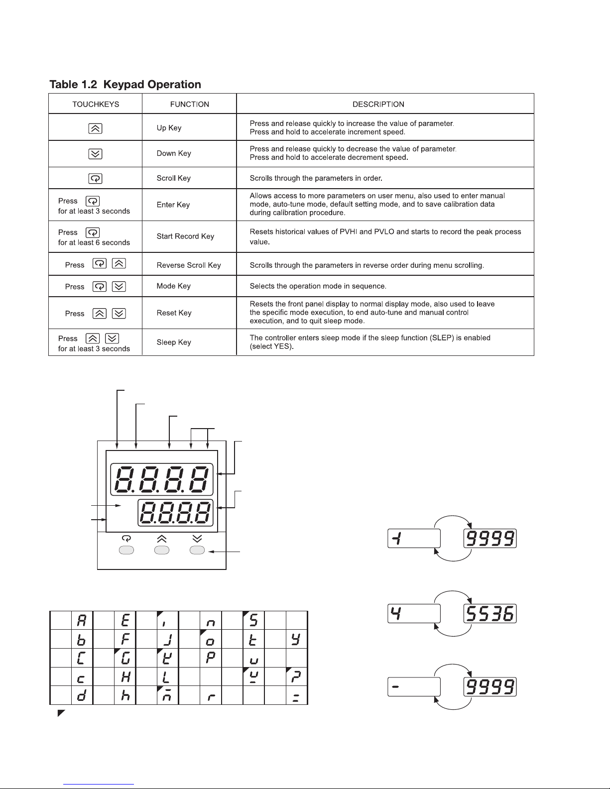
1–4 Keys and Displays
Alarm 1 Indicator
Alarm 2 / Output 2 Indicator
Process Value Indicator
Process Unit Indicator
Upper Display,
to display process value,
menu symbol and error
code etc.
Lower Display,
to display set point value,
parameter value or control
output value etc.
3 Silicone Rubber Buttons
for ease of control setup
and set point adjustment.
Set point
Value
Indicator
Output 1
Indicator
A1 A2 PV
°F
SV
OUT
For a number with decimal point the
display will be shifted one digit right:
-19999 will be displayed by:
45536 will be displayed by:
-9999 will be displayed by:
How to display a 5-digit number
-199.99 will be displayed by -199.9
4553.6 will be displayed by 4553
For a number without decimal point
the display will be divided into two
alternating phases:
TEC
-9300
Indicates Abstract Characters
A E
I
N
S
X
B
F
J
O
T
Y
C
G
K
P
U
Z
c
H
L
Q
V
?
D h
M
R
W
=
°C
Figure 1.4 Front Panel Description
Table 1.3 Display Form of Characters
The unit is programmed by using the three keys on the front panel. The available key functions are listed in the following table.
4
1–4 Keys and Displays continued…
5
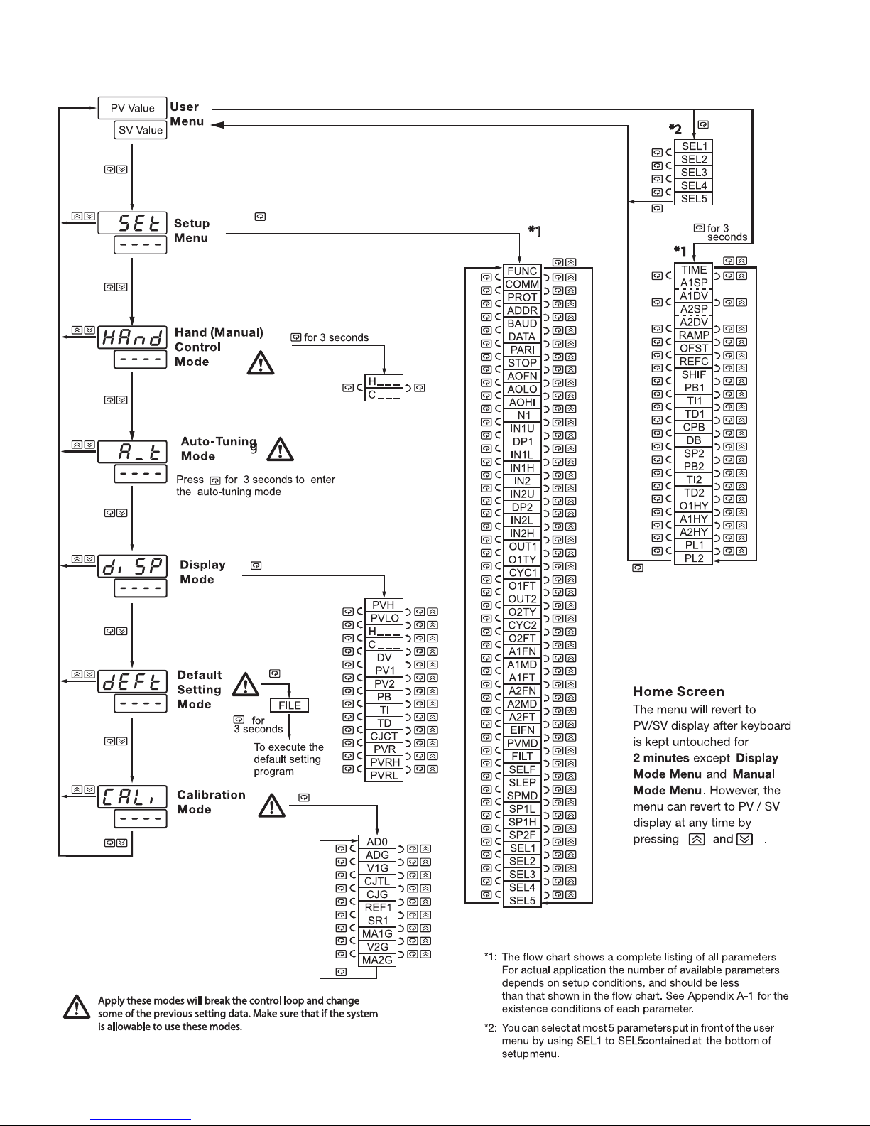
1–5 Menu Overview
e
6
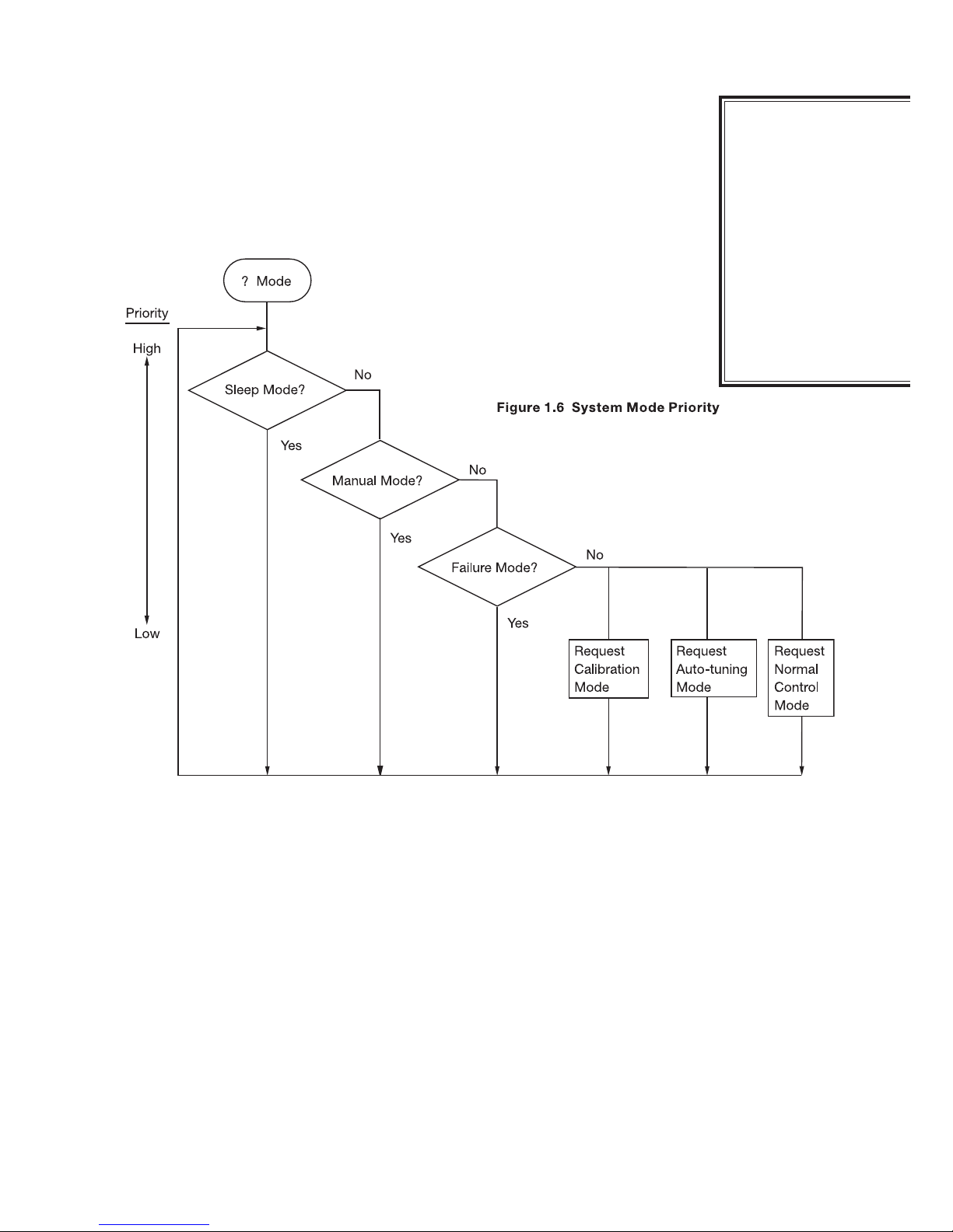
1–6 System Modes
The controller performs closed loop control in its normal control mode condition. The
controller will maintain its normal control mode when you are operating the user menu,
setup menu, display mode, reloading default values, or applying event input signals.
Under certain conditions, the normal control mode will transfer to an exception mode.
The exception modes include: sleep mode, manual mode, failure mode, calibration
mode, and auto-tuning mode. All of these modes perform in an open loop control except
auto-tuning mode which performs ON-OFF while configuring PID values control. The
mode transfer is governed by the priority conditions. A lower priority mode can not alter
a higher priority mode, as shown in figure 1.6.
System Modes
Sleep mode:
See section 4-11.
Manual mode:
See section 3-23.
Failure mode:
See section 3-17.
Calibration mode:
See chapter 6.
Auto-tuning mode:
See section 3-20.
Normal control mode:
See section 3-24, 3-26, 4-1
Calibration mode, auto-tuning mode, and normal control mode are in the
same priority level. Sleep mode is in the highest priority level.
7
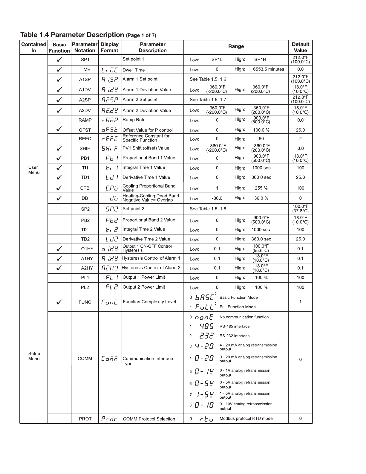
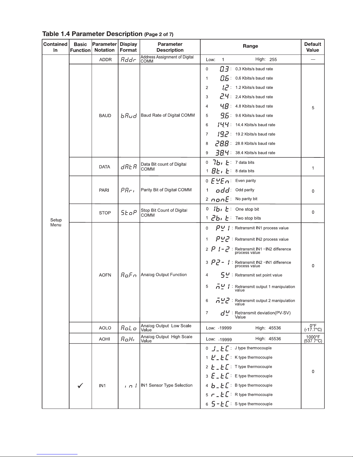
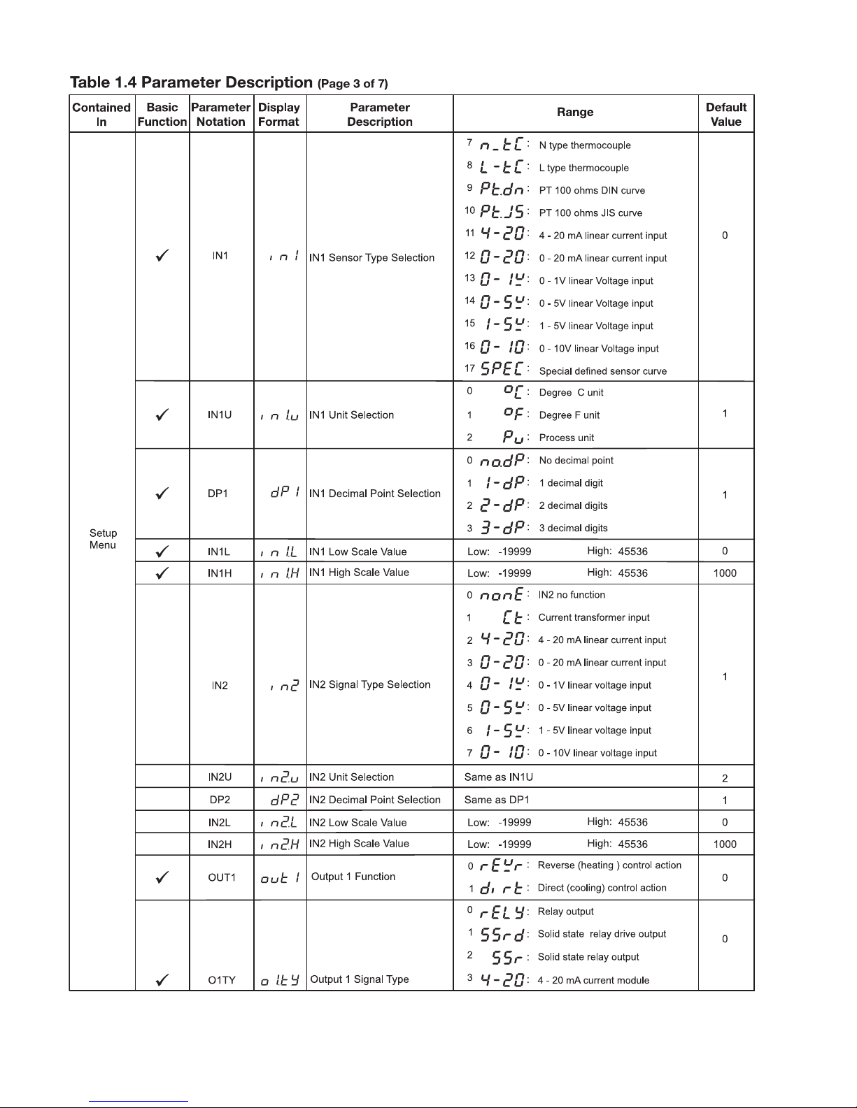
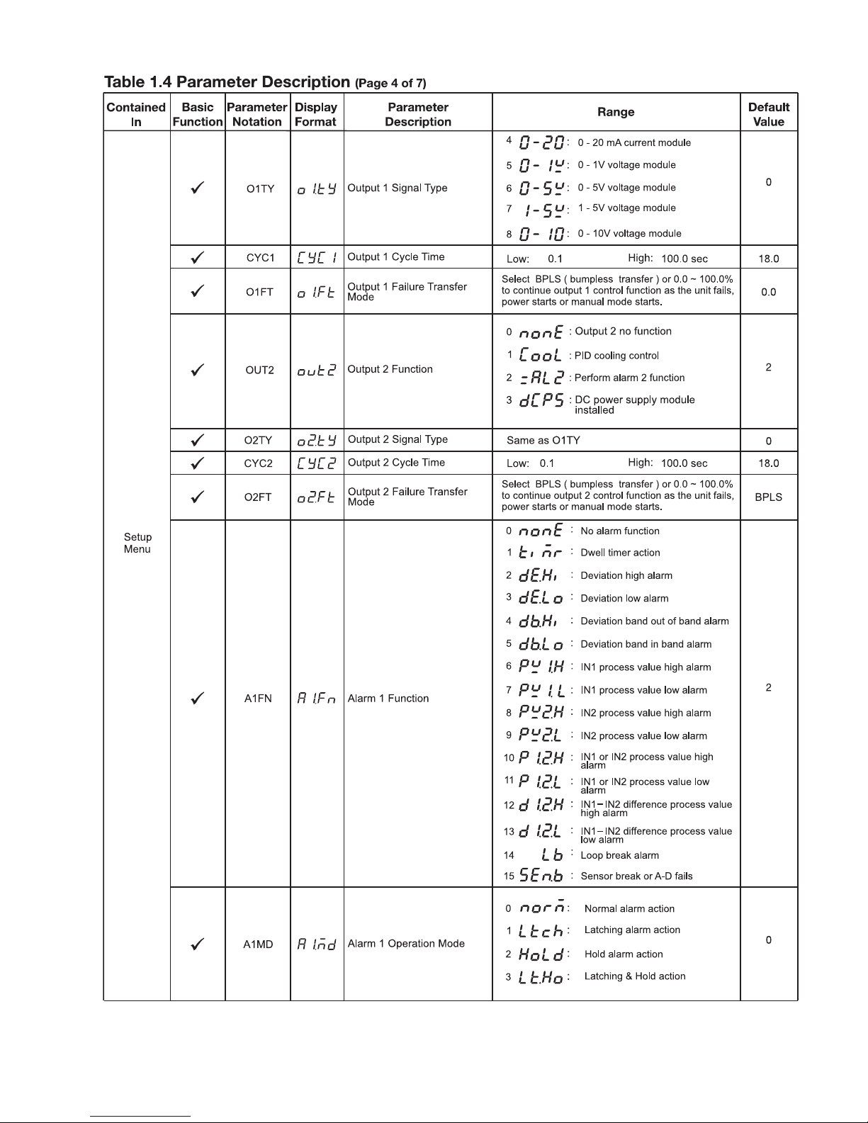
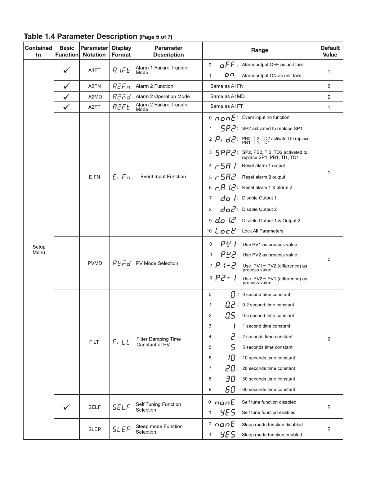
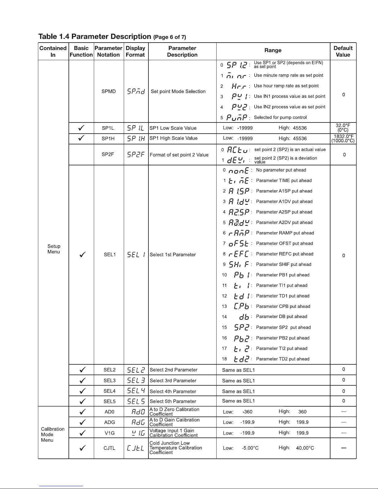
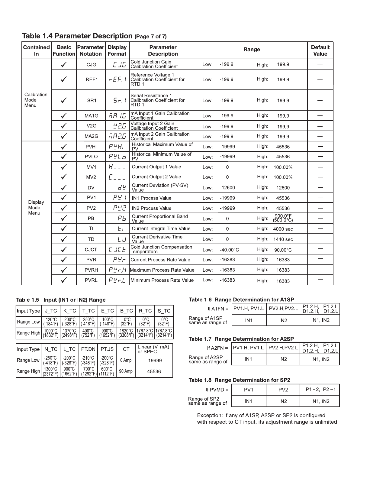
1–7 Parameter Description
8
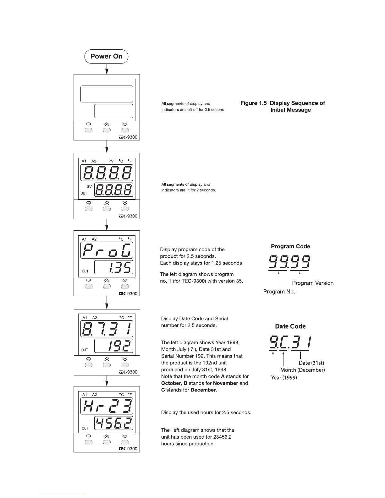
NOTE: For RS-232:
Short J1, Open/Cut J2
Using RS-232 will disable Event Input Function
NOTE: Parameter 1N1 continued on next page
9
10
NOTE: Parameter O1TY continued on next page
11
12
Note: Calibration menu is for supplier configuration use only.
13
14
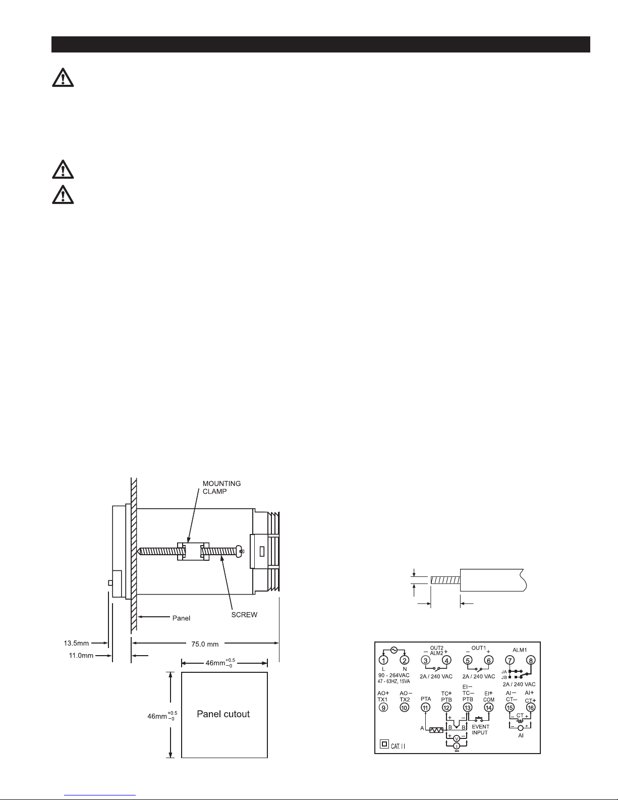
Chapter 2 Installation
Figure 2.1 Mounting Dimensions
Figure 2.2 Lead Termination
Figure 2.3 Rear Terminal Connection Diagram
4.5 ~ 7.0 mm
0.18" ~ 0.27"
2.0 mm
0.08" max.
Dangerous voltage capable of causing death can be pres-
ent in this instrument. Before installation or beginning
any troubleshooting procedures, the power to all equipment must
be switched off and isolated. Units suspected of being faulty
must be disconnected and removed to a properly equipped workshop for testing and repair. Component replacement and internal
adjustments must be made by a qualified maintenance person
only.
To minimize the possibility of fire or shock hazards, do
not expose this instrument to rain or excessive moisture.
Do not use this instrument in areas under hazardous con-
ditions such as excessive shock, vibration, dirt, moisture,
corrosive gases, or oil. The ambient temperature of the areas
should not exceed the maximum rating specified in chapter 8.
2–1 Unpacking
Upon receipt of the shipment, remove the unit from the carton
and inspect the unit for shipping damage.
If there is any damage due to transit, report the damage and file
a claim with the carrier.
Write down the model number, serial number, and date code for
future reference when corresponding with our service center.
The serial number (S/N) is labeled on the box and the housing of
the controller .
2–2 Mounting
Make the panel cutout to fit the dimensions shown in figure 2.1.
Remove both mounting clamps and insert the controller into the
panel cutout. Reinstall the mounting clamps. Gently tighten the
screws in the clamp until the controller front panel fits snugly in
the cutout .
2–3 Wiring Precautions
• Before wiring, verify the correct model number and options on
the label. Switch off the power while checking.
• Care must be taken to ensure that the maximum voltage rating
specified on the label is not exceeded.
• It is recommended that the power for these units be protected
by fuses or circuit breakers rated at the minimum value possible.
• All units should be installed in a suitable enclosure to prevent
live parts from being accessible to human hands and metal
tools. Metal enclosures and/or subpanels should be grounded in
accordance with national and local codes.
• All wiring must conform to appropriate standards of good practice and local codes and regulations. Wiring must be suitable
for the voltage, current, and temperature rating of the system.
• Beware not to over-tighten the terminal screws. The torque
should not exceed 1 N-m (8.9 lb-in or 10 KgF-cm).
• Unused control terminals should not be used as jumper points
as they may be internally connected, causing damage to the
unit.
• Verify that the ratings of the output devices and the inputs as
specified are not exceeded.
• Except for thermocouple wiring, all wiring should use stranded
copper conductor with a maximum gage of 14 AWG.
• Electrical power in industrial environments contains a certain
amount of noise in the form of transient voltage and spikes.
This electrical noise can adversely affect the operation of
microprocessor-based controls. For this reason the use of
shielded thermocouple extension wire which connects the sensor to the controller is strongly recommended. This wire is a
twisted-pair construction with foil wrap and drain wire. The
drain wire is to be attached to ground in the control panel only.
15
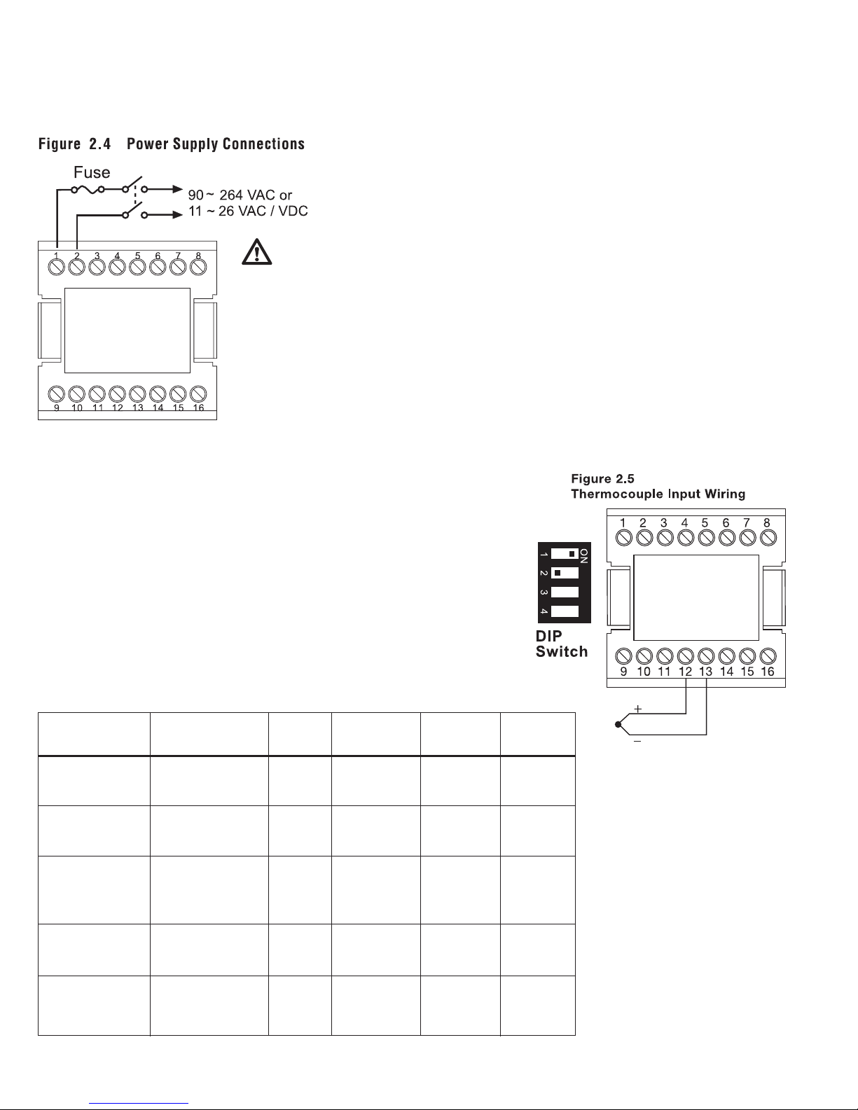
2–4 Power Wiring
The controller is supplied to operate at 11–26VAC/VDC or
90–264VAC. Check that the installation voltage corresponds to
the power rating indicated on the product label before connecting
power to the controller .
This equipment is
designed for installation
in an enclosure which provides
adequate protection against
electrical shock. Metal enclosures must be connected to
earth ground.
Local requirements regarding electrical installation
should be rigidly observed.
Consideration should be given
to prevent unauthorized personnel from gaining access to
the power terminals.
2–5 Sensor Installation Guidelines
Proper sensor installation can eliminate many problems in a
control system. The probe should be placed so that it can detect
any temperature change with minimal thermal lag. In a process
that requires fairly constant heat output, the probe should be
placed close to the heater. In a process where the heat demand is
variable, the probe should be close to the work area. Some experiments with probe location are often required to find the optimum position.
In a liquid process, the addition of a stirrer will help eliminate thermal lag. Since a thermocouple is basically a point
measuring device, placing more than one thermocouple in parallel can provide an average temperature readout and produce
better results in most air-heated processes.
The proper sensor type is also a very important factor in
obtaining precise measurements. The sensor must have the
correct temperature range to meet the process requirements. In
special processes, the sensor might have additional requirements such as leak-proof, anti-vibration, antiseptic, etc.
Standard sensor limits of error are ±4°F (±2°C) or 0.75% of
sensed temperature (half that for special) plus drift caused by
improper protection or an over-temperature occurrence. This
error is far greater than controller error and cannot be corrected on the sensor except by proper selection and replacement .
2–6 Thermocouple Input Wiring
The thermocouple input connections are shown in figure 2.5. The correct type of
thermocouple extension lead-wire or compensating cable must be used for the entire
distance between the controller and the thermocouple, ensuring that the correct
polarity is maintained throughout. Joints in the cable should be avoided, if possible.
If the length of the thermocouple plus the extension wire is too long, it may affect
the temperature measurement. A 400 ohms K type or a 500 ohms J type thermocouple lead resistance will produce approximately 1°C temperature error .
The color codes used on the thermocouple extension leads are shown in table 2.1.
Table 2.1 Thermocouple Cable Color Codes
Thermocouple Cable British American German French
Type Material BS ASTM DIN NFE
T
* blue * blue * brown * blue
J
* black * black * blue * black
Nickel-Chromium
K (Ni-Cr)
Nickel-Aluminum
(Ni-Al)
R Pt-13%Rh, Pt
S Pt-10%Rh, Pt
* green * green * white * green
B
Wire * grey * grey Wire
Copper (Cu)
Constantan (Cu-Ni)
Iron (Fe)
Constantan (Cu-Ni)
Pt-30%Rh
Pt-6%Rh
+ white + blue + red + yellow
– blue – red – brown – blue
+ yellow + white + red + yellow
– blue – red – blue – black
+ brown + yellow + red + yellow
– blue – red – green – purple
* red * yellow * green * yellow
+ white + black + red + yellow
– blue – red – white – green
Use + grey + red Use
Copper – red – grey Copper
* Color of overall sheath
16
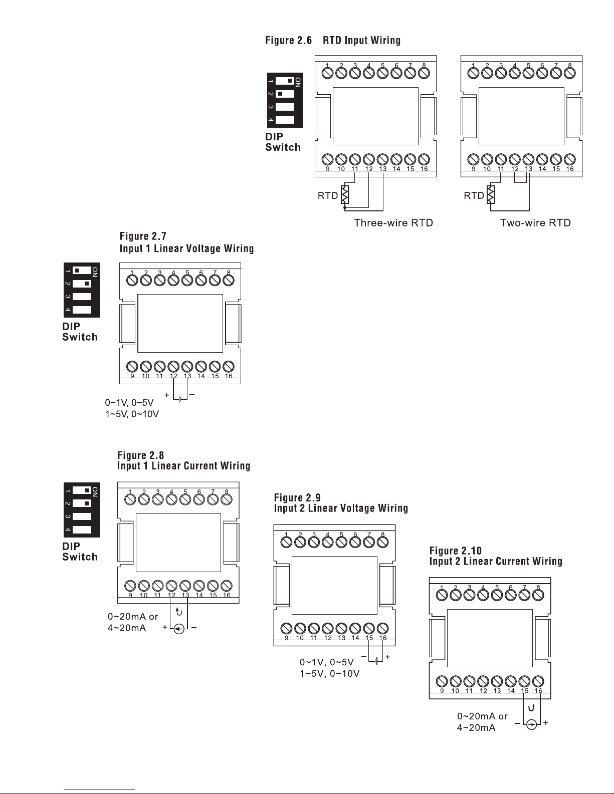
2–7 RTD Input Wiring
The RTD connections are shown in figure
2.6, with the compensating lead connected to
terminal 12. For two-wire RTD inputs, terminals
12 and 13 should be linked. A three-wire RTD
offers the capability of lead resistance compensation, provided that the three leads are the same
gauge and equal in length.
For the purpose of accuracy, two-wire RTD
should be avoided, if possible. A 0.4 ohm lead
resistance in a two-wire RTD will produce 1°C
temperature error.
2–8 Linear DC Input Wiring
DC linear voltage and linear current connections for input 1 are shown in
figure 2.7 and figure 2.8.
DC linear voltage and linear current connections for input 2 are shown in
figure 2.9 and figure 2.10.
17
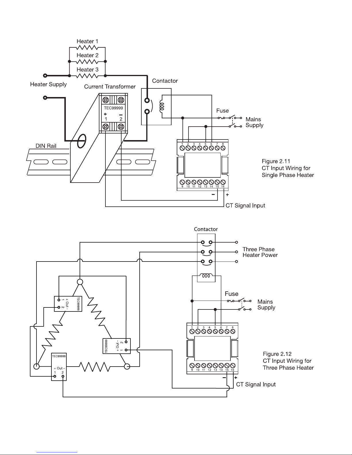
2–9 CT/Heater Current Input Wiring
Make sure that the total current through TEC99999 does not exceed 100A rms in a 3-Phase system.
18
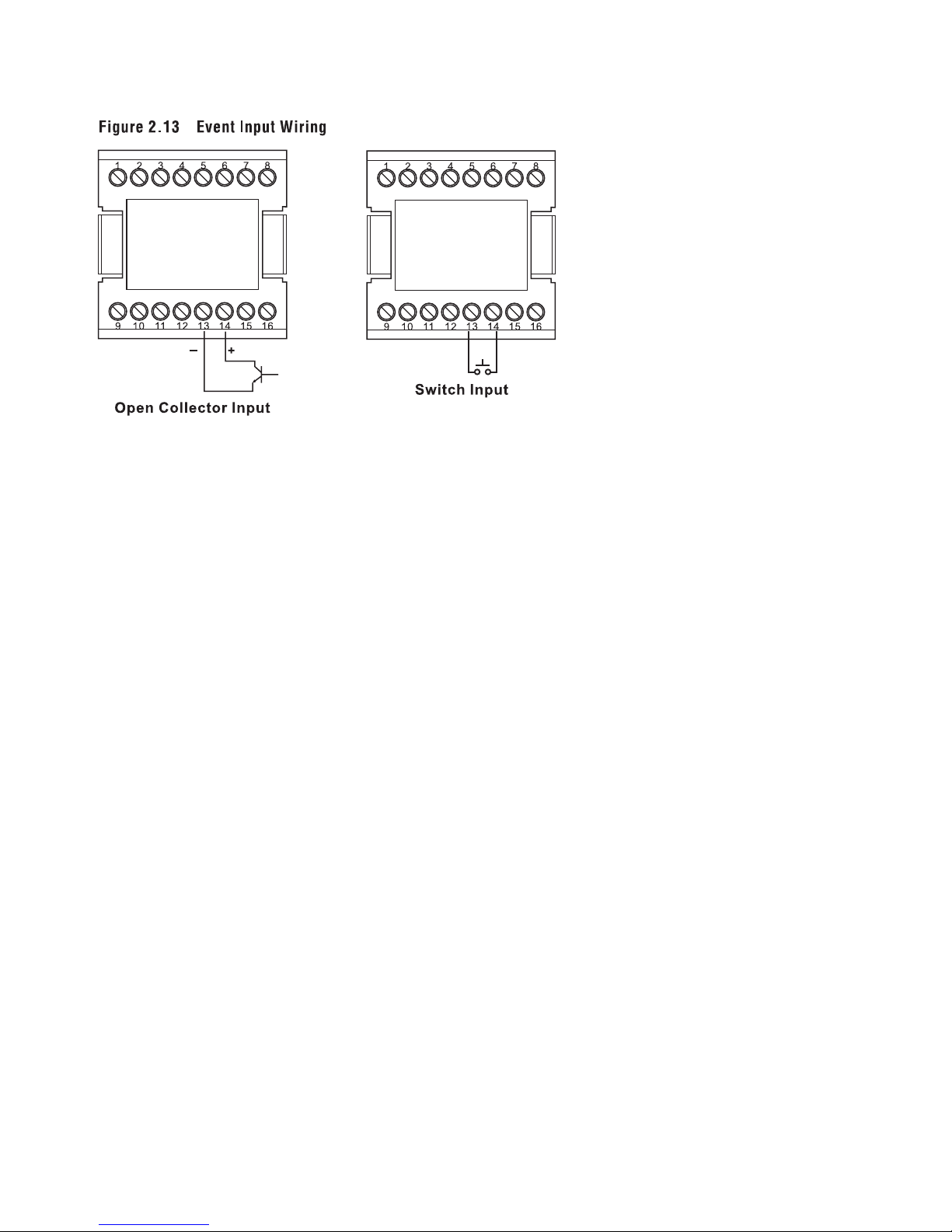
2–10 Event Input wiring
The event input can accept a switch signal as well
as an open collector signal. The event input function (EIFN) is activated when the switch is closed
or an open collector (or a logic signal) is pulled
down.
Also refer to section 4-1 for event input functions.
19
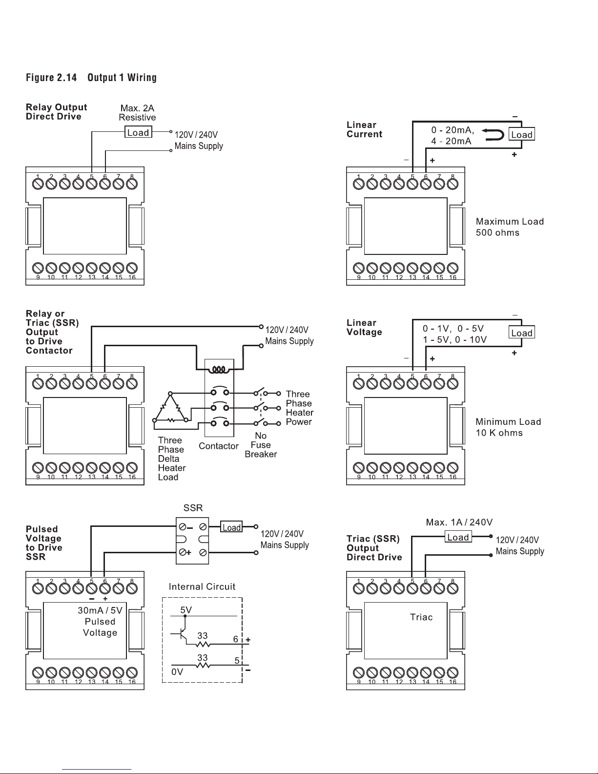
2–11 Output 1 Wiring
20
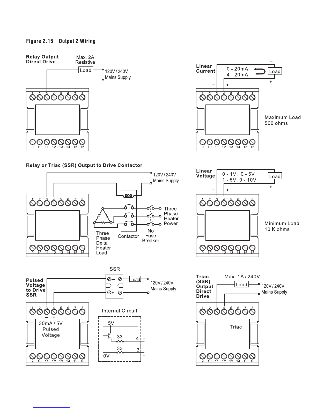
2–12 Output 2 Wiring
21
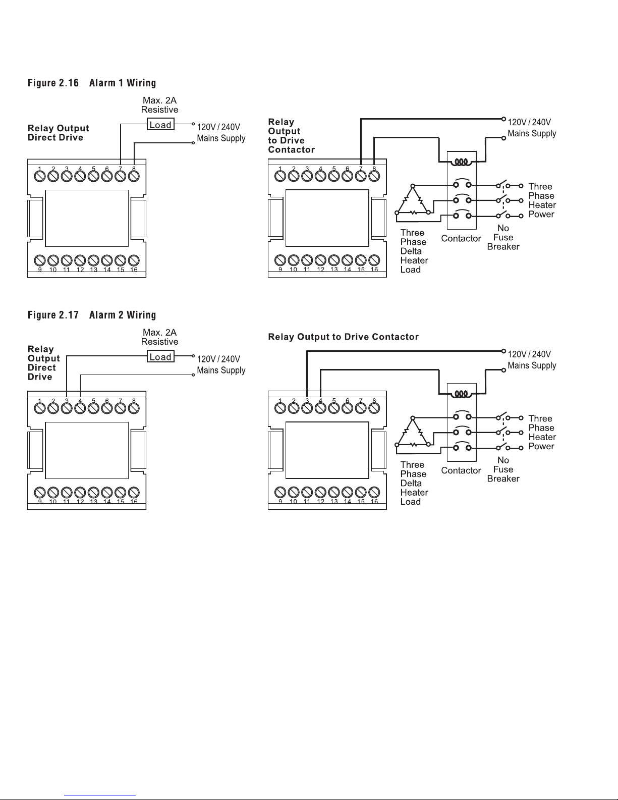
2–13, 2–14 Alarm 1 and 2 Wiring
Note: Both Form A and B contacts are available for the alarm 1 relay.
Order the correct form for alarm 1 to suit your needs.
22
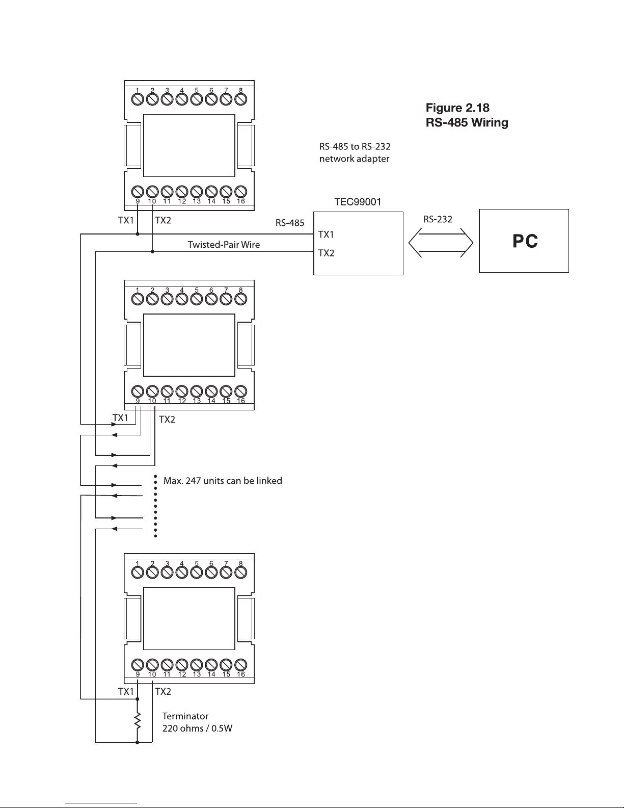
2–15 RS-485
23
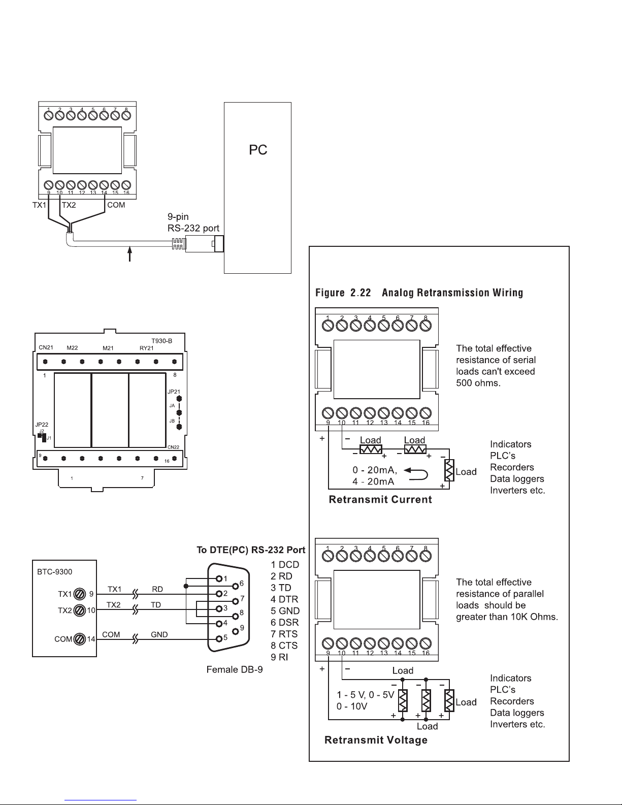
2–16 RS-232
Figure 2.20 Location of Jumper JP22
Figure 2.21 Configuration of RS-232 Cable
Figure 2.19 RS-232 Wiring
TEC99014
Note: If the TEC-9300 is configured for RS-232 communication, the EI (event input) is disconnected internally. The unit can
no longer perform event input function (EIFN).
When you connect an RS-232 module (CM94-2) to the connectors on the CPU board (C930), jumper JP22 on the terminal
board (T930) must be modified as following: J1 must be shorted
and J2 must be cut and left open. The location of JP22 is shown
in the diagram below, left (Fig. 2.20).
2–17 Analog Retransmission
If you use a conventional 9-pin RS-232 cable instead of
TEC99014, the cable must be modified according to the circuit diagram above.
24
 Loading...