

Page 1
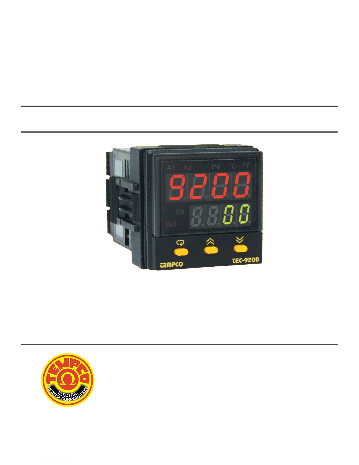
User's Manual
TEC-9200
Self-Tune Fuzzy/PID
Process/Temperature Controller
TEMPCO Electric Heater Corporation
607 N. Central Avenue
Wood Dale, IL 60191-1452 USA
Tel: 630-350-2252
800-323-6859
Fax: 630-350-0232
website: http://www.tempco.com
Copyright © 2003, Tempco Electric Heater Corporation, all rights reserved.
Revision 6/2003
Page 2

Warning Symbol
This symbol calls attention to an operating procedure, practice, or the like which, if not correctly performed or adhered
to, could result in personal injury or damage to or destruction of part or all of the product and system. Do not proceed
beyond a warning symbol until the indicated conditions are fully understood and met.
CONTENTS
1. Introduction
2. Numbering System
3. Specifications
4. Installation
5. Operation
6. Recalibration
7. Error Messages and Diagnosis
Information in this user's manual is subject to change without notice.
Copyright © 2003, Tempco Electric Heater Corporation, all rights reserved. No part of this publication may be
reproduced, transmitted, transcribed or stored in a retrieval system, or translated into any language in any form by any
means without the written permission of Tempco Electric Heater Corporation.
Page 3
1. Introduction
TEC-9200 Fuzzy Logic plus PID microprocessor-based controller incorporates a bright, easy to read, 4-digit LED display which indicates
the process value. Fuzzy Logic technology enables a process to reach a predetermined set point in the shortest time, with the minimum
of overshoot during power-up or external load disturbance. The units are housed in a 1/16 DIN case, measuring 48mm x 48mm with
75mm behind-panel depth. The units feature three touch keys to select the various control and input parameters. Using a unique function,
you can determine which parameters are accessible by the user. You can also put up to five parameters at the front of the user menu by
using SEL1 to SEL5 found in the setup menu. These are particularly useful to OEM's as it is easy to limit access and configure the menu
to suit the specific application.
TEC-9200 is powered by 20–32 or 90–264VAC supply, incorporating a 3 amp control relay output and dual 3 amp alarm relay outputs as
standard with a second alarm that can be configured in the second output for cooling purposes or as a dwell timer. Alternative output options
include SSR drive, triac, 4–20mA and 0–10 volts. TEC-9200 is fully programmable for PT100, thermocouple types J, K, T, E, B, R, S, N,
0–20mA, 4–20mA, and voltage signal input, with no need to modify the unit.
Digital communications format RS-485 or 4–20mA retransmission are available as an additional option. These options allow the TEC9200 to be integrated with supervisory control systems and software, or alternatively to drive remote displays, chart recorders, or data
loggers.
For nearly a hundred years, PID control has been used and has proven to be an efficient controlling method by many industries, yet
PID has difficulty dealing with some sophisticated systems such as second and higher order systems, long time-lag systems, during set
point changes and/or load disturbances, etc. The PID principle is based on a mathematical model which is obtained by tuning the
process. Unfortunately, many systems are too complex to describe precisely in numerical terms. In addition, these systems may vary
from time to time. In order to overcome the imperfections of PID control, Fuzzy Technology was introduced. What is Fuzzy Control? It
works like a good driver. Under different speeds and circumstances, he can control a car well based on previous experience, and does
not require knowledge of the kinetic theory of motion. Fuzzy Logic is a linguistic control which is different from numerical PID control. It
controls the system by experience and does not need to simulate the system precisely as a PID controller would.
The function of Fuzzy Logic is to adjust PID parameters internally in order to make manipulation of output value MV more flexible and
adaptive to various processes.
The Fuzzy Rule may work like this:
If the temperature difference is large, and the temperature rate is large, then ∆MV is large.
If the temperature difference is large, and the temperature rate is small, then ∆MV is small.
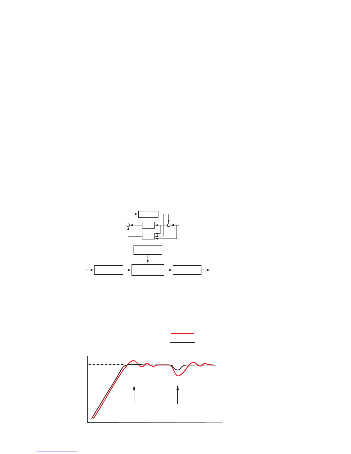
PID+Fuzzy Control has been proven to be an efficient method to improve control stability as shown by the comparison curves below:
3
Figure 1.1
Fuzzy PID System Block
Figure 1.2 Fuzzy PID
Enhances Control
Stability
PID + FUZZY CONTROL
MV PV
+
PROCESS
+
PID
FUZZY
_
+
SV
Figure 1.1
Fuzzy PID System Block
Digital
information
Fuzzy Rule
Language
information
Fuzzy Inference
Engine
DefuzzifierFuzzifier
Digital
information
PID control with properly tuned
PID + Fuzzy control
Temperature
Set point
Warm Up
Load Disturbance
Figure 1.2 Fuzzy PID
Enhances Control
Stability
Time
Page 4

2. Numbering System
TEC-9200-_ _ _ _ _ _ _ _
1 2 3 4 5 6 7 8
(1) Power Input
4 . . . . . . . . 90–264VAC
5 . . . . . . . . 20–32VAC/VDC
9 . . . . . . . . Other
(2) Signal Input (can be programmed in the field)
5 . . . . . . . . TC-Configurable: J, K, T, E, B, R, S, N
6 . . . . . . . . RTD-Configurable: DIN or JIS
7 . . . . . . . . Linear-mV or mA: 4–20, 0–20mA; 0–1, 0–5, 1–5, 0–10VDC
9 . . . . . . . . Other
(3) Range Code
1 . . . . . . . . Field configurable
9 . . . . . . . . Other
(4) Control Mode
3 . . . . . . . . Field configurable
9 . . . . . . . . Other
(5) Output 1
0 . . . . . . . . None
1 . . . . . . . . Relay-3A/240VAC
2 . . . . . . . . Pulse DC for SSR drive-24VDC (20mA max)
3 . . . . . . . . 4–20mA, linear (max. load 500 ohms)
4 . . . . . . . . 0–20mA, linear (max. load 500 ohms)
5 . . . . . . . . 0–10VDC, linear (min. impedance 500K ohms)
6 . . . . . . . . Triac-SSR output 1A/240VAC
9 . . . . . . . . Other
(6) Output 2
0 . . . . . . . . None
(7) Alarm
0 . . . . . . . . None
2 . . . . . . . . Dual relays-2A/240VAC, field configurable (Alarm 2 can be used for output 2/cooling)
9 . . . . . . . . Other
(8) Data Communications
0 . . . . . . . . None
1 . . . . . . . . RS-485
2 . . . . . . . . 4–20mA retransmission
3 . . . . . . . . 0–20mA retransmission
9 . . . . . . . . Other
4
Page 5

3. Specifications
Input
*Accuracy = Linearity Error + Cold Junction Compensating Error + Lead Compensating Error + Offset Drift Error
Linear voltage input impedance: 100K ohms
Cold junction compensation: 0.1°F/°F ambient typical
Sensor break protection: Configurable by operator
External resistance: 100 ohms max.
Normal mode rejection: 60dB
Common mode rejection: 120dB
Sample rate: 5x/second
Control
Proportion band: 0–360°F (0–200°C)
Reset (Integral): 0–3600 seconds
Rate (Derivative): 0–1000 seconds
Ramp rate: 0–99.99°F (0–55.55°C)/minute
Dwell: 0–9999 minutes
On-off: Adjustable hysteresis 0.1–19.9°F (0–11.0°C)
Cycle time: 0–99 seconds
Control action: Direct (for cooling) and reverse (for heating)
Power
Rating: 90–264VAC, 50/60Hz
Consumption: Less than 5VA
Environmental and Physical
Safety: UL 873, CSA 22.2/142-87, IEC 1010-1
Protection: NEMA 4X, IP65
EMC emission: EN50081-1, EN55011
EMC immunity: IEC801-2, IEC801-3, IEC801-4
Sensor Input Type Range (°F) *Accuracy (°F) Range (°C) *Accuracy (°C)
J Iron/Constantan -58 to 1832°F ±3.6°F -50 to 1000°C ±2°C
K Chromel/Alumel -58 to 2500°F ±3.6°F -50 to 1370°C ±2°C
T Copper/Constantan -454 to 752°F ±3.6°F -270 to 400°C ±2°C
E Chromel/Constantan -58 to 1382°F ±3.6°F -50 to 750°C ±2°C
B Pt30%RH/Pt6%RH 32 to 3272°F ±5.4°F 0 to 1800°C ±3°C
R Pt13%RH/Pt 32 to 3182°F ±3.6°F 0 to 1750°C ±2°C
S Pt10%RH/Pt 32 to 3182°F ±3.6°F 0 to 1750°C ±2°C
N Nicrosil/Nisil -58 to 2372°F ±3.6°F -50 to 1300°C ±2°C
RTD PT 100 ohms (DIN) -328 to 752°F ±0.72°F -200 to 400°C ±0.4°C
RTD PT 100 ohms (JIS) -328 to 752°F ±0.72°F -200 to 400°C ±0.4°C
Linear 4–20mA -1999 to 9999 ±0.05% -1999 to 9999 ±0.05%
Linear 0–20mA -1999 to 9999 ±0.05% -1999 to 9999 ±0.05%
Linear 0–1VDC -1999 to 9999 ±0.05% -1999 to 9999 ±0.05%
Linear 0–5VDC -1999 to 9999 ±0.05% -1999 to 9999 ±0.05%
Linear 1–5VDC -1999 to 9999 ±0.05% -1999 to 9999 ±0.05%
Linear 0–10VDC -1999 to 9999 ±0.05% -1999 to 9999 ±0.05%
5
Page 6
Operating temperature: 14 to 122°F (-10 to 50°C)
Humidity: 0 to 90% RH (non-condensing)
Insulation: 20M ohms min. (500VDC)
Breakdown: 2000V (AC), 50/60Hz, 1 minute
Vibration: 10–55 Hz, amplitude 1mm
Shock: 200m/s² (20g)
Moldings: Flame retardant polycarbonate
Dimensions: H: 1.875” (48mm) x W: 1.875” (48mm) x D: 3.375” (86mm)
Depth behind panel: 2.875” (73mm)
Weight: 4 oz. (110g)
4. Installation
Dangerous voltage capable of causing death can be present in this instrument. Before installation or beginning any
troubleshooting procedures, the power to all equipment must be switched off and isolated. Units suspected of being
faulty must be disconnected and removed to a properly equipped workshop for testing and repair. Component
replacement and internal adjustments must be made by a qualified maintenance person only.
To minimize the possibility of fire or shock hazards, do not expose this instrument to rain or excessive moisture.
Do not use this instrument in areas under hazardous conditions such as excessive shock, vibration, dirt, moisture,
corrosive gases, or oil. The ambient temperature of the areas should not exceed the maximum rating specified.
4–1 Unpacking
Upon receipt of the shipment, remove the unit from the carton and inspect the unit for shipping damage. If there is any
damage due to transit, report the damage and file a claim with the carrier.
Write down the model number, serial number, and date code for future reference when corresponding with our service
center. The serial number (S/N) and date code (D/C) are labeled on the box and the housing of the controller.
4–2 Mounting
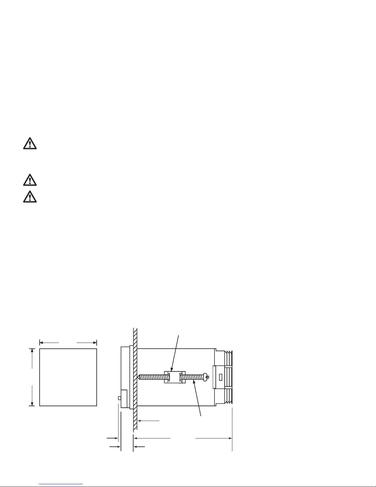
Make the panel cutout to fit the dimensions shown in figure 4.1.
Remove both mounting clamps and insert the controller into the panel cutout. Reinstall the mounting clamps. Gently
tighten the screws in the clamp until the controller front panel fits snugly in the cutout.
6
Figure 4.1 Mounting Dimensions
MOUNTING
CLAMP
Figure .1 Mounting Dimensions
1.81"
(46mm)
1.81"
(46mm)
Panel cutout
0.5"
(13.5mm)
0.4"
(11.0mm)
Panel
2.95"
(75.0 mm)
SCREW
Page 7
4–3 Wiring Precautions
• Before wiring, check the label to verify the correct model number and options. Switch off the power while checking.
• Care must be taken to ensure that the maximum voltage ratings specified in section 3 are not exceeded.
• It is recommended that the power source for these units be protected by fuses or circuit breakers rated at the minimum
value possible.
• All units should be installed inside a suitably grounded metal enclosure to prevent live parts from being accessible to
human hands and metal tools.
• All wiring must conform to the appropriate standards of good practice and local codes and regulations. Wiring must be
suitable for the voltage, current, and temperature ratings of the system.
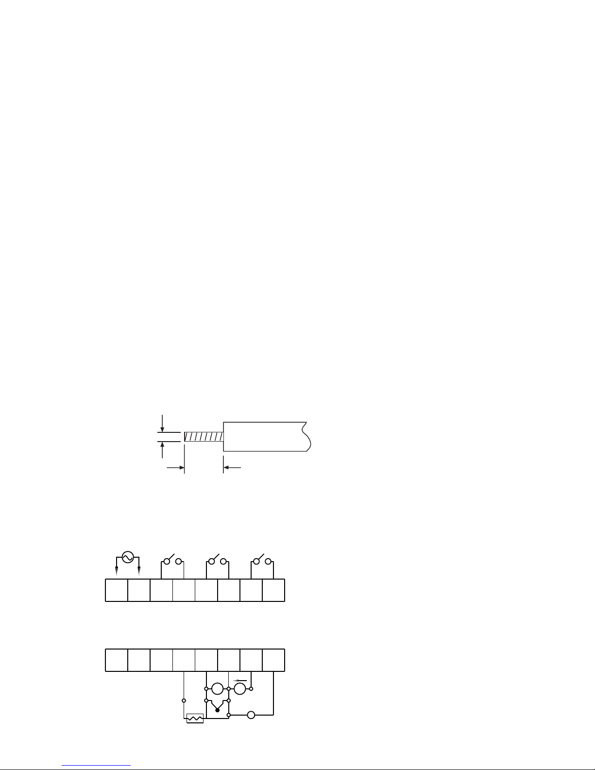
• The "stripped" leads as specified in figure 4.2 below are used for power and sensor connections.
• Beware not to over-tighten the terminal screws.
• Unused control terminals should not be used as jumper points as they may be internally connected, causing damage to
the unit.
• Verify that the ratings of the output devices and the inputs are not exceeded.
• Electrical power in industrial environments contains a certain amount of noise in the form of transient voltage and
spikes. This electrical noise can adversely affect the operation of microprocessor-based controls. For this reason we
strongly recommend the use of shielded thermocouple extension wire which connects the sensor to the controller. This
wire is a twisted-pair construction with foil wrap and drain wire. The drain wire is to be attached to ground at one end
only.
4–4 Connection and Wiring
The following connections for outputs and inputs are found on the back of the controller housing.
7
Figure 4.2 Lead Termination
2.0mm
0.08" max.
Figure .2 Lead Termination
4.5 7.0 mm
~
0.18" 0.27"
~
90-264VAC
50-60Hz
1 2
N L
AO+
AO-
TX1
TX2
109
OUT2
ALM2
- +
ALARM 1
OUT1
34 6578
TC-
TC+
mV-
COM+
14
B
0-20mA
4-20mA
mA- V-
V
-
+
0-10V
PTA
11 12
A
RTD
13
B
mV
- +
- +
T/C
- +
Figure 4.3 Rear T erminal Connections
1615
Page 8

Power Wiring
The controller is supplied to operate on 24V (20–32VAC/VDC) or 90–264VAC. Verify that the voltage of the power
supply corresponds to that indicated on the product label before connecting power to the controller.
This equipment is designed for installation in an enclosure which provides adequate protection against electrical
shock. The enclosure must be connected to earth ground.
Local requirements regarding electrical installation should be rigidly observed. Consideration should be given to prevent
unauthorized personnel from gaining access to the power terminals.
Input Wiring
Connect the appropriate sensor to terminals 12, 13, 14, 15, or 16 as indicated in figure 4.3. Make sure that the correct
sensor type is selected on the controller, and that the correct polarity is observed at both ends of the cable.
For thermocouple wiring, the correct type of extension wire must be used for the entire distance between the controller
and the thermocouple. The extension wires must be the same alloy and polarity as the thermocouple, and joints in the
cable should be avoided, if possible. The color codes used on the thermocouple extension wires are shown in table 4.1.
For wiring three-wire RTD, the two common wires should be connected to terminals 13 and 14, compensating lead
connected to terminal 13. When using a two-wire RTD, install a jumper between terminals 13 and 14. A three-wire RTD
offers the capability of lead resistance compensation, provided that all three leads are the same gauge and material, and
of equal length.
Table 4.1 International Thermocouple Cable Color Codes
* Color of overall sheath
Output Wiring
There are several types of output modules (see section 2) that can be selected for output 1 when ordering the TEC9200, depending on the control application. Make sure the output device you selected is appropriate for your application
requirements. The external connections will depend on the type of output installed. If pulsed voltage is selected, note
that pulsed voltage output is non-isolated.
Sensor Placement
Proper sensor installation can eliminate many problems in a control system. The probe should be placed so that it can
detect any temperature change with minimal thermal lag. In a process that requires fairly constant heat output, the probe
should be placed close to the heater. In a process where the heat demand is variable, the probe should be close to the
work area. Some experiments with probe location are often required to find the optimum position.
In a liquid process, the addition of a stirrer will help eliminate thermal lag. Since a thermocouple is basically a point
measuring device, placing more than one thermocouple in parallel can provide an average temperature readout and
produce better results in most air-heated processes.
Thermocouple
Type
Cable
Material
American
ANSI
BritishBSGerman
DIN
French
NFE
J Iron/Constantan
+ white
- red
* black
+ yellow
- blue
* black
+ red
- blue
* blue
+ yellow
- black
* black
K Chromel/Alumel
+ yellow
- red
* yellow
+ brown
- black
* red
+ red
- green
* green
+ yellow
- purple
* yellow
T
Copper/
Constantan
+ blue
- red
* blue
+ white
- blue
* blue
+ red
- brown
* brown
+ yellow
- black
* black
R
S
Platinum/Rhodium
+ black
- red
* green
+ white
- blue
* green
+ red
- white
* white
+ yellow
- green
* green
B Platinum/Rhodium
+ grey
- red
* grey
+ red
- grey
* grey
8
Page 9
The proper sensor type is also a very important factor in obtaining precise measurements. The sensor must have the
correct temperature range to meet the process requirements. In special processes, the sensor might have additional
requirements such as leak-proof, anti-vibration, antiseptic, etc.
Standard sensor limits of error are ±4°F (±2°C) or 0.75% of sensed temperature (half that for special) plus drift caused
by improper protection or an over-temperature occurrence. This error is far greater than controller error and cannot be
corrected on the sensor except by proper selection and replacement.
5. Operation
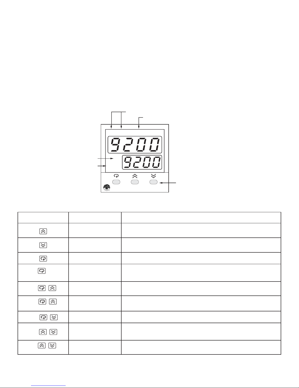
5–1 Front Panel Description
5–2 Keypad Operation
*It takes 12 seconds with power on to memorize the new value of a parameter once it has been changed.
9
Alarm Outputs
Process Value
Set Point Value
Control Output
A1 A2 PV
SV
OUT
'C
'F
3 Silicone Rubber Buttons
for ease of control setup
TEC-9200
and set point adjustment.
TOUCHKEYS FUNCTION DESCRIPTION
Press and release quickly to select which digit of a numerical parameter to change.
Press and hold to increase the value of the selected digit or to change the selection
for an index parameter.
Press and release quickly to select which digit of a numerical parameter to change.
Press and hold to decrease the value of the selected digit or to change the selection
for an index parameter.
Selects the parameter in a direct sequence. Also used to select the tool program
parameters.
Selects the parameters in higher security level, and actuates the selected tool
program whenever the display is showing a tool program.
Press
for at least 3.2 seconds
Up Key
Down Key
(Direct) Scroll Key
Long Scroll/Enter Key
Press
Press
for at least 3.2 seconds
Press
Press
Press
for at least 3.2 seconds
Reverse Scroll/Callibration
Verification Key
Lock Key
Tool Program Key
Reset/Exit Key
Autotune Key
Selects the parameters in a reverse direction during parameter scrolling, or verifies
the display accuracy for various input types during callibration.
Disables keypad operation to protect all the parameters from being tampered with.
Selects the tool programs in sequence.
Unlocks keypad operation and resets the front panel display to normal display mode,
exits tool program, or stops the autotuning function.
Starts the autotune program.
Page 10
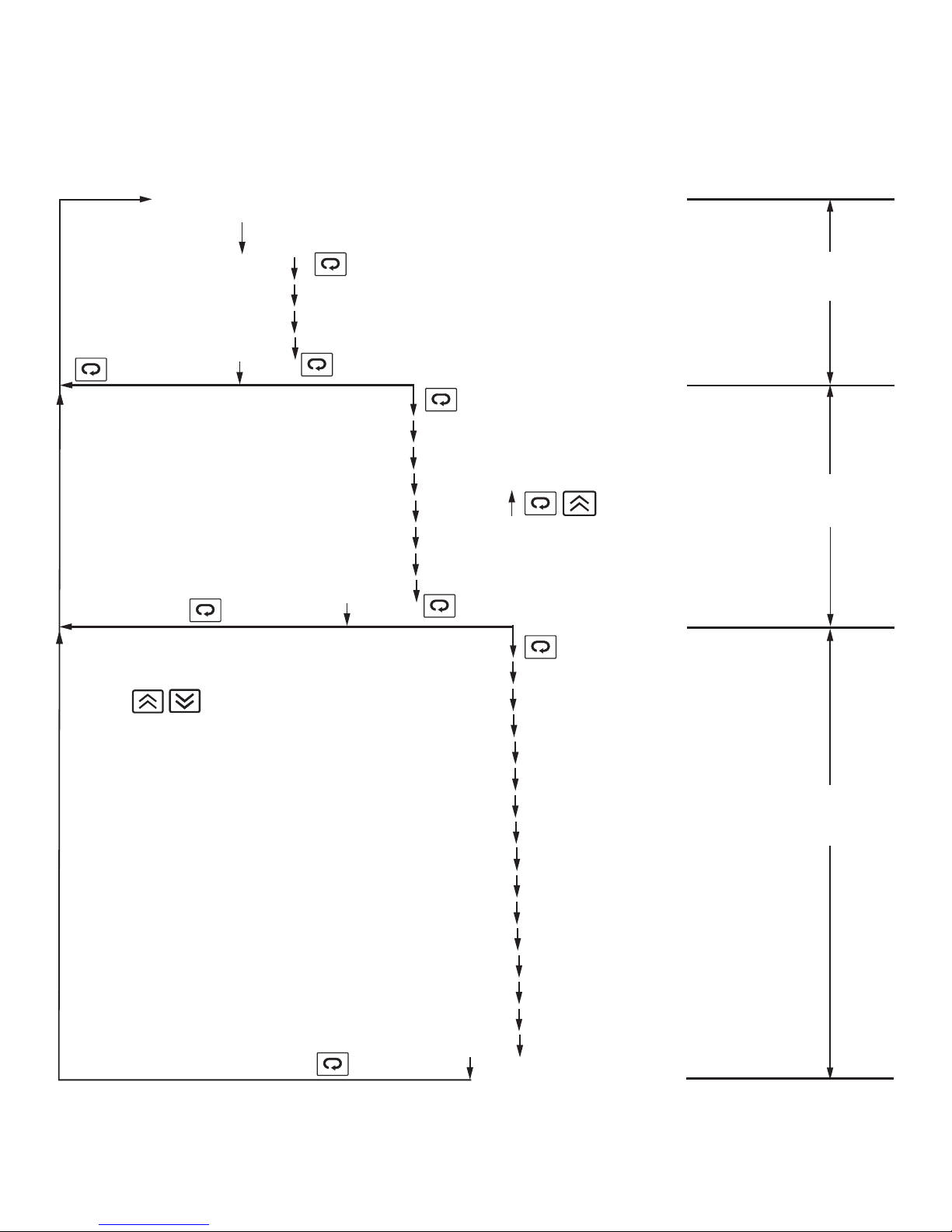
5–3 Menu Overview and Descriptions of Parameters
10
PROCESS VALUE
SET POINT VALUE
ASP1
RAMP
OFST
Short scroll
returns to PV/SV
ASP2
AhY1
AhY2
hYST
Short scroll
returns to PV/SV
Exits parameters and
returns to PV/SV
NOTE: The display will return to PV/SV
in 25 seconds if no entry is made.
ADDR
Short scroll advances forward
through parameters step by step
Hold until display stops
flashing (3.2 seconds)
SHIF
PB
TI
TD
Hold until display stops
flashing (3.2 seconds)
LO.SC
hI.SC
PL.1
PL.2
INPT
UNIT
RESO
CON.A
A1.MD
A1.SF
A2.MD
A2.SF
CYC
CCYC
C.PB
Short scroll
returns to PV/SV
D-B
Short scroll advances forward
through parameters step by step
Scrolls through parameters
step by step in reverse order
Short scroll advances forward
through parameters step by step
Security
Level 0
Security
Level 1
Security
Level 2
Page 11
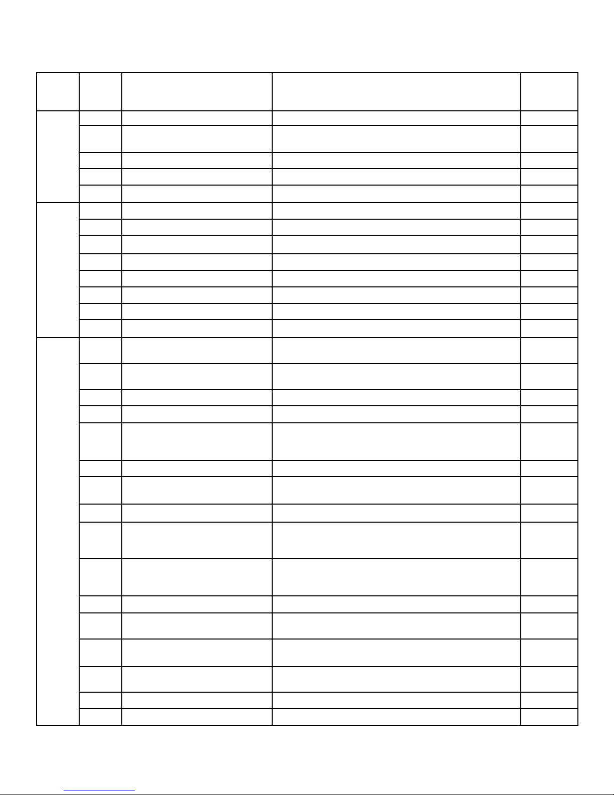
Parameter descriptions:
11
Default
Security
Level
Display
Code
Description Adjustment Range
Default
Setting
0
SV Set point value of control Low scale to high scale value 212°F
ASP1
Alarm 1 set point value or Dwell
time
Trip point within high/low scale or
0–9999 minutes (for dwell time)
18°F (10°C)
RAMP
Ramp rate 0–99.99°F/minute (0–55.55°C/minute) 0.00
OFST
Offset value for manual reset 0–100% Only functional if integral (TI) is set to 0. 0.0
ASP2
Alarm 2 set point value Trip point within high/low scale 18°F (10°C)
1
SHIF
Display shift -199–199°F (-111–111°C) 0
PB
Proportional band of Output 1 0–360°F (0–200°C) 0: for ON-OFF control 18°F (10°C)
TI
Integral (reset) time of Output 1 0–3600 seconds 120
TD
Derivative (rate) time of Output 1 0–1000 seconds 40
AhY1
Hysteresis of Alarm 1 0–19°F (0–11°C) 0
AhY2
Hysteresis of Alarm 2 0–19°F (0–11°C) 0
hYST
Hysteresis of ON-OFF control 0–19°F (0–11°C) 0
ADDR
Interface address 0–40 0
2
LO.SC
Low scale of range.
Adjust for your process
Minimum value for the selected input to high scale 0°F
hI.SC
High scale of range.
Adjust for your process
Low scale to maximum value for the selected input 999°F
PL.1
Power limit of Output 1 0–100% 100%
PL.2
Power limit of Output 2 0–100% 100%
INPT
Input type selection J, K, T, E, B, R, S, or N-TC=J, K, T, E, B, R, S, or N type
T/C
PT100 DIN (PTDN), PT100 JIS (PTJS), 4–20mA, 0–20mA,
|
J-TC
UNIT
Display units QC =°C QF =°F PU =process units (Engineering °F
RESO
Resolution NODP =No decimal point 1DP =1 decimal place
2DP =2 decimal places (only when UNIT = PU)
NODP
CON.A
Control action of Output 1 DIRT =Direct (cool) action REVR =Reverse (heat) action
REVR
A1.MD
Alarm 1 mode
DVhI=Deviation high DVLO=Deviation low
DBhI=Deviation band high DBLO=Deviation low
FShI=Full scale high FSLO=Full scale low
DVhI
A1.SF
Alarm 1 special function
NONE=No special function LTCh=Latching alarm
hOLD=Holding alarm LThO=Latching/holding alarm
TOON=Timer on as time out TOOF=Timer off as time out
NONE
A2.MD
Alarm 2 mode Same as Alarm 1 mode
DVhI
A2.SF
Alarm 2 special function
NONE=No special function LThO=Latch/hold alarm
hOLD=Hold alarm LTCh=Latch alarm..COOL=Out. 2
NONE
CYC
Proportional cycle time of Output
1
0–99 seconds, 0 for linear current/voltage output
20 for
relay output
CCYC
Cooling cycle time 0–99 seconds, 0 for linear current/voltage output
20 for
relay output
C.PB
Cooling P band 0–360°F (0–200°C) 18°F (10°C)
D-B
Deadband for PB and CPB -199–199°F (-111–111°C) 0
Page 12
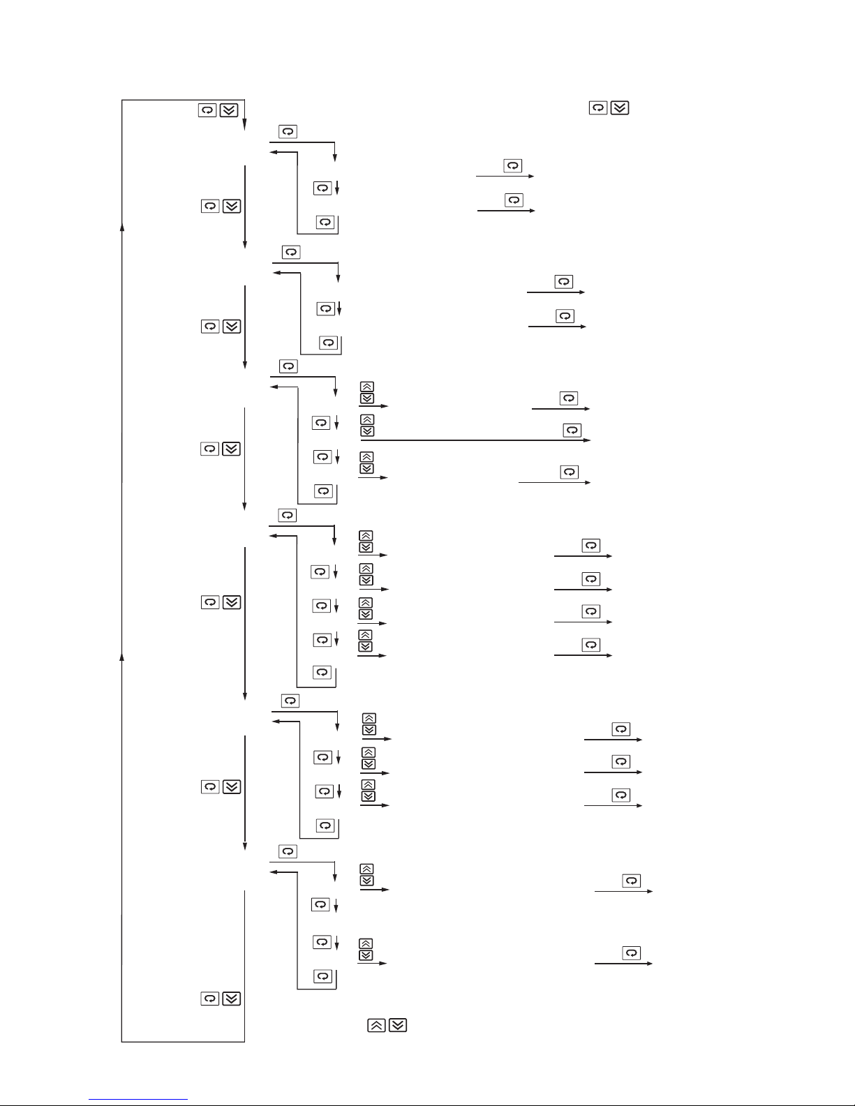
5–4 Flow Chart of Tool Programs
12
The Tool Programs menu can be entered at any time by pressing
Manual Mode
(hand control)
Used if sensor fails.
Peak Process Value
Stored minimum and
maximum values.
Calibrate
A-D converter
Fail Safe
Defines the status of
the outputs if the
sensor fails.
HAND
CONT
READ
PEAK
CALI
A-D
FAIL
SAFE
h___
C___
hI.PV
LO.PV
T___
A___
D___
OUT.1
ALM.1
ALM.2
OUT.2
Indicates percentage power
of output 1 (heating)
Indicates percentage power
of output 2 (cooling)
Indicates maximum (peak) process value
Indicates minimum (peak) process value
or
Adjusts Cold Junction compensation
code (range -19.9-42.7)
or
or
Adjusts Drift compensation code
(range -6.6-6.6)
or
Select the status for Output 1: ON or OFF
or
Select the status for Alarm 1: ON or OFF
or
Select the status for Alarm 2: ON or OFF
or
Select the status for Output 2: ON or OFF
Long
Long
Adjust the percentage of on-time for output 1
using the up and down keys. Range: 0-100%
(Not functional with TEC-9200)
Long
Long
Long
Long
Long
Resets the maximum process value
Resets the minimum process value
Calibrate the A-D converter and enter
the Cold Junction compensation code
Calibrate the 0-20mA and enter it
Enter the Drift compensation code
Long
Long
Long
Long
Enters the selection
Enters the selection
Enters the selection
Enters the selection
Lock Parameters
Parameter levels can
be locked out to
prevent tampering.
Configure Security Levels
Parameters can be
moved from one
security level to
another.
LEVL
=0: Puts parameter in
Level 0
=1: Puts parameter in
Level 1
=2: Puts parameter in
Level 2
LOCK
PARA
CONF
LEVL
or
LEV.0
LEV.1
LEV.2
ASP.1
Displays the rest of the parameters
according to the standard sequence.
D-B
Select LOCK or FREE for all Level 0 parameters
or
Select LOCK or FREE for all Level 1 parameters
or
Select LOCK or FREE for all Level 2 parameters
or
Change the security level of the selected parameter
or
Change the security level of the selected parameter
Exits Tool Programs
Long
Long
Long
Long
Long
Enters the selection
Enters the selection
Enters the selection
Enters the selection
Enters the selection
Page 13

5–5 Setting-Up Procedures
When power is applied, the model number and software version number of the controller will be displayed for 3.2
seconds, then all of the display segments and LED indicators will light up for 3.2 seconds. After this initial cycle, the
controller will enter normal display mode, showing the process value in the upper display, and the set point value in the
lower display. The upper display will flash continuously in the following cases:
1. while executing autotune program
2. while executing manual mode program
3. to warn that the next parameter is a higher level parameter (as the scroll key is pressed). The warning will remain for
3.2 seconds. If the scroll key is released after this duration elapses, the upper display will show the code of the next
parameter, and the lower display will show its value. Otherwise, it will return to normal display mode.
The upper display will blink for a moment when a new value of a parameter is being written into the non-volatile memory.
The upper display is also used to display error messages if an abnormal condition occurs.
Parameter Definitions
SV—Set Point Value
This parameter is the desired target of the process. It can be adjusted within the range defined by the low scale value
(Lo.SC) and high scale value (hi.SC). The default value is 212°F (100°C).
ASP1—Alarm 1 Set Point Value or Dwell Time
This sets the levels at which alarm 1 will function if A1.SF (alarm 1 special function) is set for an alarm function. If A1.SF
is selected for dwell timer (to.on or to.of), then ASP1 is the timer setting in minutes. The dwell timer starts counting when
the process value reaches the set point value. See sections 5–10 and 5–13 for more details.
RAMP—Ramp Rate
This controls the heating (or cooling) rate of the process. The setting is in degrees per minute. Set this parameter to
zero if no ramp is needed.
OFST—Offset Value for Manual Reset
This parameter will only function if the integral time (TI) is set to zero. OFST is then used to compensate for any
deviation between the process temperature and the set point temperature. If the process temperature stabilizes below
the set point, set a positive value for OFST; if the process temperature stabilizes above the set point, set a negative
value for OFST. Wait for the system to stabilize, then make additional adjustments as needed.
ASP2—Alarm 2 Set Point Value
This sets the levels at which alarm 2 will function if A2.SF is set for an alarm function. If A2.SF is set for cooling, alarm 2
will preform as a cooling output which is governed by CCyC, C.pb, and d-b. ASP2 will then have no effect.
SHIF—Shift Process Value
This value will be added to or subtracted from the process value. This can be used to compensate if the sensor reads a
different temperature than the item being sensed.
PB, TI, and TD—PID Values
Proportional band, Integral (reset) and Derivative (rate) time constants. These must be set as close as possible to the
process application requirements. See section 5–7 for more details.
AHY1, AHY2—Hysteresis Values of Alarm 1 and Alarm 2
These values define the deadbands for the alarms. The alarms will not change state until the temperature is outside the
deadband.
HYST—Hysteresis Value of On-Off Control
This parameter defines the deadband when on-off control is being used and PID control has been disabled.
13
Page 14

ADDR—Interface Address
This parameter provides an identity code for the RS-485 interface. Note that no two controllers communicating with the
same computer can have the same identity code. Ignore this parameter if the controller does not use the RS-485
interface.
LO.SC, HI.SC—Low/High Scale Range
If thermocouple or PT100 is selected as the input type (INPT), these parameters are used to define the range of the set
point adjustment. If linear process input is selected, these parameters are used to define the range of the process value
and set point adjustment. See section 5–14 for more details.
PL.1, PL.2—Power Limit for Heating and Cooling Outputs
These parameters limit the maximum output percentage of power for heating or cooling during warm up and in
proportional band. If the control has relay or pulsed voltage outputs, the percentage of “on” time will be decreased. If the
control has linear current or linear voltage outputs, the actual output levels will be decreased. These are only used for
processes where heating or cooling at full speed would be dangerous or would produce unsatisfactory results. For
normal applications, these parameters are set at 100%.
INPT—Input Type
This is used to program the control for the type of input sensor used.
UNIT—Process Units
This parameter is used to select the units displayed. For linear process input, Pu (process unit) can be selected in
addition to °F or °C.
RESO—Resolution (Set Decimal Point Placement)
This parameter defines the position of the decimal point in the process and set point values. no.dP=no decimal point;
1.dP=one decimal point; 2.dP=two decimal points. Note that 2.dP can only be used for linear process input when Pu is
selected for UNIT.
CON.A—Control Action of Output 1
This selects reverse (heating) action or direct (cooling) action for output 1.
A1.MD, A2.MD—Alarm Mode Selection for Alarm 1 and Alarm 2
This sets the type of alarm required: deviation alarm, band alarm, or process alarm. See section 5–10 for more details.
A1.SF—Alarm 1 Special Function
Use this parameter to select any special functions required for use with alarm 1. Latching or holding alarms can be
selected (see section 5–10), or to.on or to.of can be selected if dwell timer function is required (see section 5–13).
A2.SF—Alarm 2 Special Function
Select hold function or latch function for alarm 2, or select COOL to reconfigure alarm 2 as a cooling output.
CYC, CCYC—Proportional Cycle Time of Output 1 and Cooling Output
Select a proper value for the process in accordance with the output devices used. Note that CCYC is only used if A2.SF
has been set for cooling. See the following section on initial setup for further discussion.
C.PB, D-B—Cooling Proportional Band, Cooling Deadband
Only used if A2.SF has been set for cooling. Otherwise, they may be ignored. See section 5–9 for more details.
Initial Setup
Use the keypad to view the value of each parameter. Use the up and down keys to set the correct value for each
parameter. Note that the new value of each parameter is automatically entered into nonvolatile memory.
The adjustment of proportional cycle time (CYC and CCYC) is related to the speed of the process response and the
output device fitted. For a faster process, it is recommended to use SSR (select SSR drive output) or SCR (select linear
current or voltage output) to drive the load. The relay output is used to drive a magnetic contactor in a slow process. If a
14
Page 15
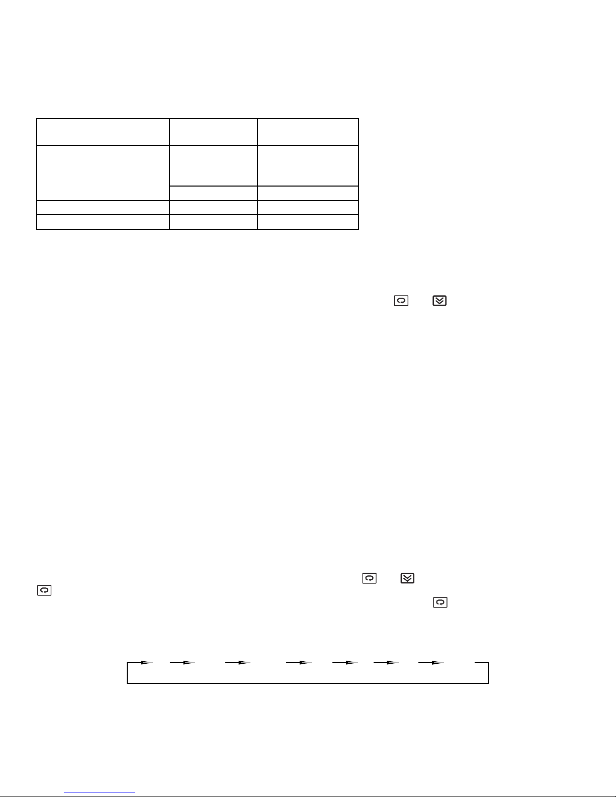
long cycle time is selected for a fast process, the process may become unstable as a result. Theoretically, the smaller
the cycle time selected, the better the control that can be achieved. However, for a relay output, the cycle time should be
as large as possible (while maintaining satisfactory control) in order to maximize the life of the relay.
The following table provides cycle time recommendations for avoiding premature relay failure:
Note: In an on-off control (when PB is set to zero) the cycle time parameter may be ignored.
FAIL-SAFE Configuration
FAIL-SAFE is a tool program used to define as on or off the status of output 1 (OUT1), output 2 (OUT2), alarm 1 output
(ALM1), and alarm 2 output (ALM2) in the event of a failure. Press and release and repeatedly until FAIL-SAFE
appears in the display windows. Press the scroll key until the desired output is shown in the upper display. Now press
and hold the up or down key to change the status as shown in the lower display. Note that if the desired setting is
different from the original one, a long scroll (pressing the scroll key for 3.2 seconds) will be required to enter the new
value before proceeding to the next tool parameter. If the FAIL-SAFE status is not critical for a process if the controller
should fail, then this section can be ignored.
LOCK Parameter
The flow chart in section 5–4 shows how to reach LOCK PARA and from there reach LEVEL (LEV.0–LEV.2), which is
shown in the upper display, and the lock status of that level (LOCK or FREE), which is shown in the lower display. For
example, if you select LOCK for LEV.2 and press the scroll key for 3.2 seconds to enter the selection, the all parameters
in level 2 can no longer be changed. A LOCK message will appear in the upper display if someone attempts to change a
locked parameter.
Configuring Security Levels of Parameters
One of the features of this controller is the ability to assign the security level for each parameter individually. One of four
levels (level 0, level 1, level 2, or level 3) can be assigned to any parameter. The parameters with lower security levels
will be displayed before parameters with higher security levels as one cycles through the parameters using the scroll
key. Furthermore, level 3 parameters are not displayed on the front panel, so any unused parameters can be assigned
security level 3 and removed from the viewing rotation completely.
As shown in section 5.4, to configure a new level for a parameter, press and to reach CONF LEVL, then press
to display the desired parameter. The lower display will indicate the level of the selected parameter. You can now
change the level for that parameter using the up and down keys. Finally, press and hold for 3.2 seconds or longer to
enter the new value. For example, if ASP1 and RAMP are set as level 0, PB, TI, and TD are set as level 1, ASP2 is set
at level 2, and all other parameters are set as level 3, the scrolling sequence of parameters will be as follows:
Output Device
(OUT1 or Cooling Output)
Cycle Time
(CYC or CCYC)
Load (resistive)
Relay
20 sec. or more
recommended
10 sec. minimum
2A/250VAC
or contactor
5 sec. minimum 1A/250VAC
Solid State Relay Drive 1–3 sec. SSR
Linear Current/Voltage 0.1 sec. Phase control module
15
ASP1
RAMP
PB
TI
TDSV
ASP2
Page 16

5–6 Auto-Tune
The auto-tuning process is performed at the set point. The process will oscillate around the set point during the
auto-tuning process. Set the set point to a lower value if overshooting beyond the normal process value would be likely
to cause damage.
The auto-tune program should be applied:
• During initial set-up
• When the set point is changed substantially from the previous auto-tune
• When the control results are unsatisfactory
When preparing to run the auto-tune program:
• Make sure that all parameters are configured correctly.
• Make sure that PB is not set to zero, because the auto-tune program cannot be run in on-off control mode.
• Set the set point at the normal operating process value (or at a lower value if overshoot is likely to cause damage) and
use normal load conditions.
• Press and hold the up and down keys for 3.2 seconds then release together. The upper display will flash while the
auto-tune program is running.
Auto-tune “teaches” the controller the main characteristics of the process. It “learns” by cycling the output on and off.
The results are measured and used to calculate the optimum PID values for the process which are then automatically
entered into the nonvolatile memory.
During the second period of the auto-tune program, the controller performs PID control to verify the results, and an
OFST value is obtained and entered in the memory.
To stop the auto-tune program, press the up and down keys and release them together. The upper display will stop
flashing, indicating that the auto-tune program has been aborted. Once the controller has entered the verifying period,
auto-tuning cannot be stopped.
5–7 Tuning the Controller Manually
• Make sure that all parameters are configured correctly.
• Set PB to zero. Set HYST to minimum (0.1°F or 0°C).
• Set the set point at the normal operating process value (or at a lower value if overshoot is likely to cause damage) and
use normal load conditions.
• Switch on the power supply to the heater. Under these conditions, the process value will oscillate about the set point
and the following parameters should be noted:
1. The peak to peak variation (P) of the first cycle in °F or °C (i.e., the difference between the highest value of the first
overshoot and the lowest value of the first undershoot).
2. The cycle time (T) of the oscillation in seconds (see figure below).
The control setting should then be adjusted as follows:
PB=P (°F or °C)
TI=T (seconds)
TD=T/4 (seconds)
16
PV
P
SV
T
Time
Page 17
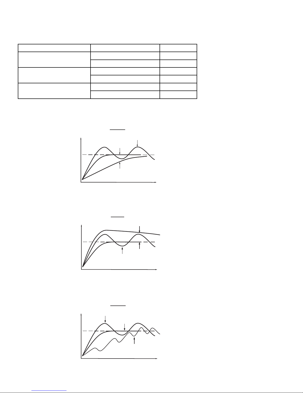
The PID parameters determined by the above procedures are rough values. If the control results using the above values
are unsatisfactory, the following rules may be used to further adjust the PID parameters:
Effects of PID adjustments on process response:
17
Adjustment Sequence Symptom Solution
Proportional Band (P)
PB
Slow response Decrease PB
High overshoot or oscillations Increase PB
Integral Time (I)
TI
Slow response Decrease TI
Instability or oscillations Increase TI
Derivative Time (D)
TD
Slow response or oscillations Decrease TD
High overshoot Increase TD
P action
PV
Set point
PV
Set point
PB too low
Perfect
PB too high
Time
I action
TI too high
Perfect
TI too low
Time
PV
Set point
TD too low
D action
Perfect
TD too high
Time
Page 18
5–8 On-Off Control
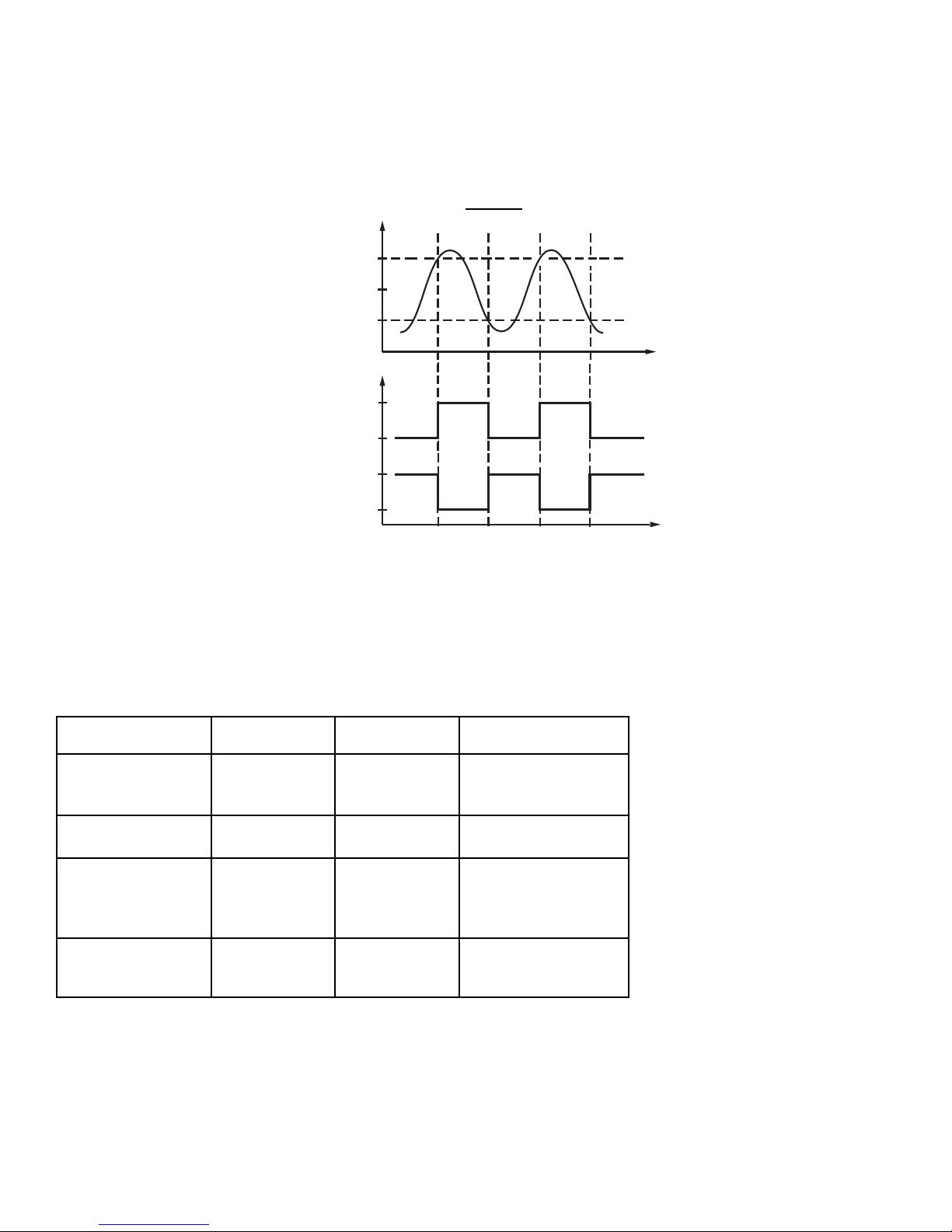
If the alarm output is configured as an alarm function, it basically performs as an on-off control. If you adjust the P band
to PB=0, you can get an additional channel of on-off control with variable hysteresis. Hysteresis, also called differential
or deadband, is measured in degrees. See the figure below for a description of on-off control.
On-off control may create excessive process variation from the set point, even if the hysteresis is set at the minimum
possible value. When using on-off control, the parameters TI, TD, and CYC will have no effect on the system, and both
manual mode and the auto-tune program will be disabled.
5–9 Cooling Control
Cooling control options:
Output
Configurations
Heating Output Cooling Output Adjusted Parameters
On-Off Cooling
(no heating)
None OUT1
CONA=DIRT
HYST
SV
Proportional Cooling
(no heating)
None OUT1
CONA=DIRT
PB, TI, TD, CYC, SV
Heating +
On-Off Cooling
OUT1 ALM2
CONA=REVR
A2SF=NONE
A2MD=DVHI (or FSHI)
AHY2, SV (or ASP2)
Heating +
Proportional Cooling
OUT1 ALM2
CONA=REVR
A2SF=COOL
CPB, DB, CCYC, SV
18
P action
PV
SP+HYST/2
SP
SP–HYST/2
OUTPUT
Reverse 100%
Action
(CONA=REVR)
Direct 100%
Action
(CONA=DIRT)
0%
0%
Time
Time
Page 19
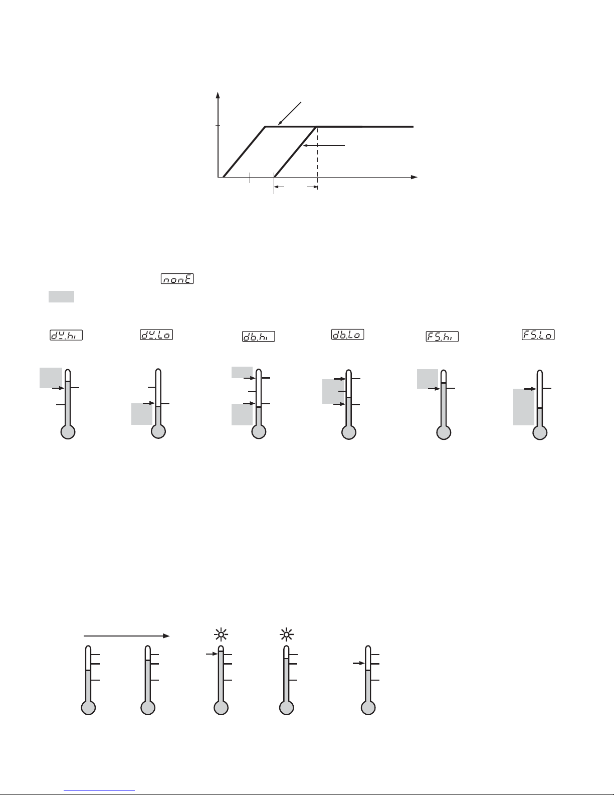
Functions of CPB and DB: the cooling P band CPB and the deadband DB are measured in degrees.
5–10 Alarm
There are at most two independent alarms that can be made available by adjusting the alarm special function
parameters A1SF and A2SF. While the descriptions in this section are based on alarm 1, they can also be applied to
alarm 2.
• Latch Alarm: A1SF=LTCH
When selected, the alarm output and indicator latch as the alarm occurs. The alarm output and indicator will be
energized even if the alarm condition has been cleared, unless the power is shut off.
• Hold Alarm: A1SF=HOLD
When selected in any alarm mode, prevents an alarm on power up. The alarm is enabled when the process value
reaches the set point value.
• Latch and Hold Alarm: A1SF=LT.HO
When selected in any alarm mode, prevents an alarm on power up. The alarm is enabled when the process value
reaches the set point value. Thereafter, the alarm acts as a latch alarm as described above.
• Hysteresis (AHY1) adjustment
Example: no special function used with deviation high alarm, SV=100°C, ASP1=10°C, AHY1=4°C
19
Cooling
Output
DB Negative
100%
DB Positive
0%
SV
CPB
SV+DB
PV (∞F or ∞C)
•• No special function: A1SF=
: Alarm on
A1MD
Deviation
high alarm
ON
SV
SV+ASP1
A1MD
Deviation
low alarm
SV
ON
SV+ASP1
(ASP1 negative)
A1MD
Deviation band
high alarm
ON
SV
ON
SV+ASP1
SV-ASP1
A1MD
Deviation band
low alarm
ON
SV
ON
SV+ASP1
SV-ASP1
A1MD
Full scale
high alarm
ON
ASP1
A1MD
Full scale
low alarm
ON
ASP1
Process proceeds
112 112112 112 112
108 108108 108 108
100 100100 100 100
Below 108∞C
alarm off
Below 108∞C
alarm off
ON
Above 112∞C
alarm on
Above 108∞C
alarm stays on
OFF
Below 108∞C
alarm off
Page 20
5–11 Viewing the Output Percentage Power
Scroll through the tool programs until you come to HAND CONTROL , then press the scroll key. The
upper display will now show the process value and the lower display will show the percentage power of output 1 (for
example, ). To view the cooling output, press scroll again. If alarm 2 is configured as a cooling output
(A2SF=COOL), the lower display will now show the percentage power of alarm 2 (for example, ). If alarm 2 is
configured as an alarm, this percentage power reading is invalid and should be ignored.
The range of percentage power is from 0–100%. If the unit is configured for on-off control, only 0 or 100 will be
displayed. For a proportional control, the output percentage power represents the percentage of the duty cycle the
output spends in the ON-state. (e.g., if cycle time CYC=10 seconds, and the output spends 4 seconds on and 6 seconds
off during each duty cycle, the lower display would read )
5–12 Manual Control
Follow the procedures from section 5–11, then press and hold the scroll key for 3.2 seconds and release. The controller
will now enter manual control mode. The upper display will begin to flash and the output percentage can now be
adjusted using the up and down keys. Note that manual control mode is not available if the control is configured for onoff control (PB=0). If it is attempted, an error message (OPER) will appear in the upper display.
Manual control mode should be used:
• When teaching the process
• If the controller fails
Manual control mode is an open loop control. The process may rise to a dangerous temperature. Special attention
must be paid to the process in order to prevent damage to the system.
5–13 Ramp and Dwell
The controller can be configured to act either as a fixed set point controller or as a single ramp controller on power up.
This function enables the user to set a predetermined ramp rate (RAMP) to allow the process to reach the set point
temperature gradually, producing a “soft start” effect.
A dwell timer is incorporated in the controller. Alarm 1 can be configured to provide either a dwell function or a soak
function when used in conjunction with the ramp function.
Ramp Function
If the ramp function is selected, the process will increase or decrease at a predetermined rate during initial power up, or
with set point changes or process variations.
The ramp rate is determined by the “RAMP” parameter, which can be adjusted through a range from 0–99.99°F/minute
(0–55.55°C/minute). If the “RAMP” parameter is set to zero, the ramp function is disabled.
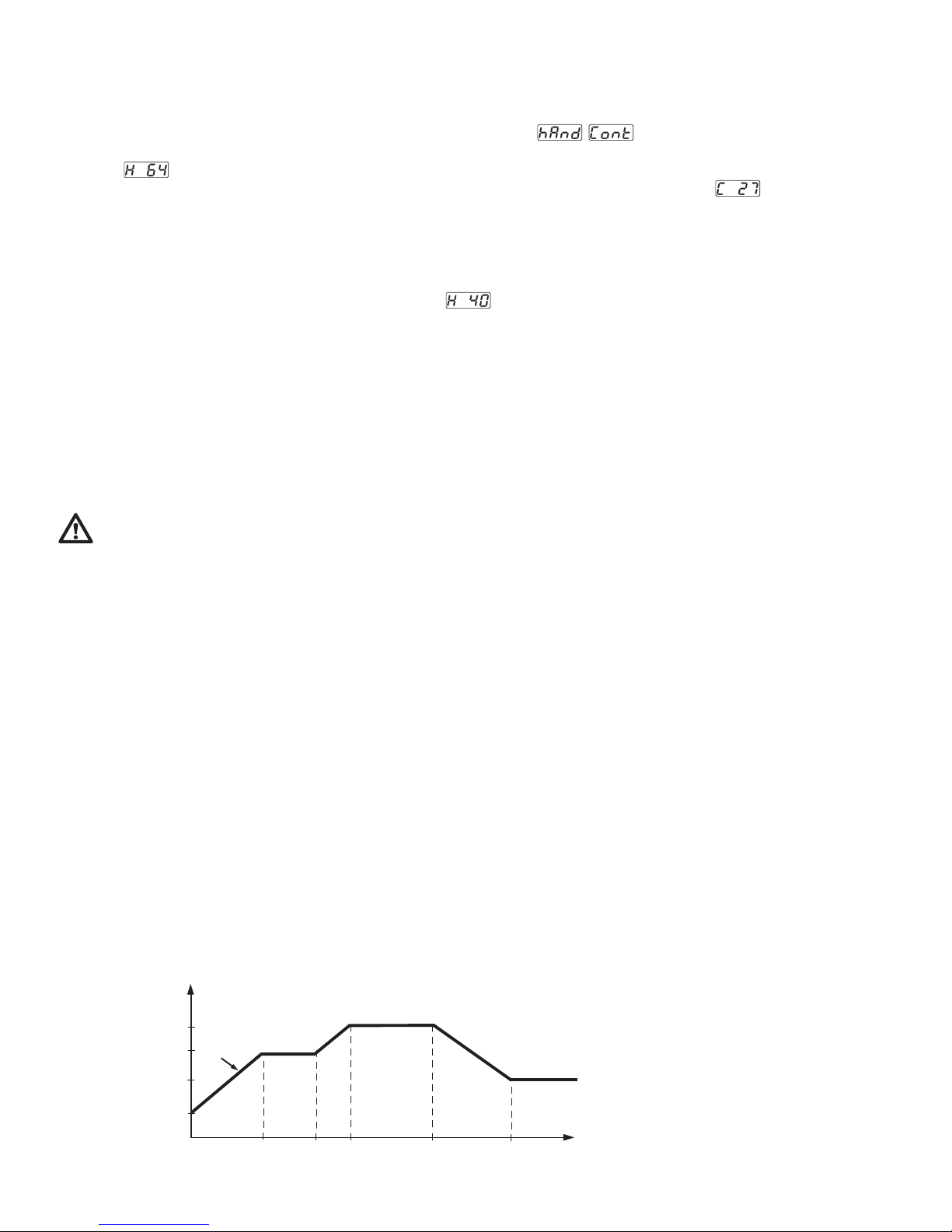
In the example below, RAMP is set at 5.00°F/minute, the ambient temperature is 50°F, and power is applied at zero
time. The process value climbs to the initial set point of 150°F over a period of 20 minutes. The process temperature is
held until the set point value is changed to 175°F at 40 minutes. The process value then climbs to the new set point over
a period of 5 minutes and the new set point is held. At 70 minutes, the set point value is decreased to 100°F and the
process value falls to the new set point over a period of 15 minutes.
20
∞F
175
150
PV
100
50
0
20
40 45
70
85
Time (minutes)
Page 21
Ramp and Soak Function
The soak function is enabled by configuring alarm 1 to act as a dwell timer. If A1SF is set for TOON (time out on), the
alarm 1 relay will act as a timer contact, with the contact being open at power up and closing after the time set in ASP1
has elapsed. If A1SF is set for TOOF (time out off), the alarm 1 relay will perform the reverse action. If the heater (or
contactor coil) is wired in series through the alarm 1 relay and the out 1 relay, the controller will act as a guaranteed
soak controller.
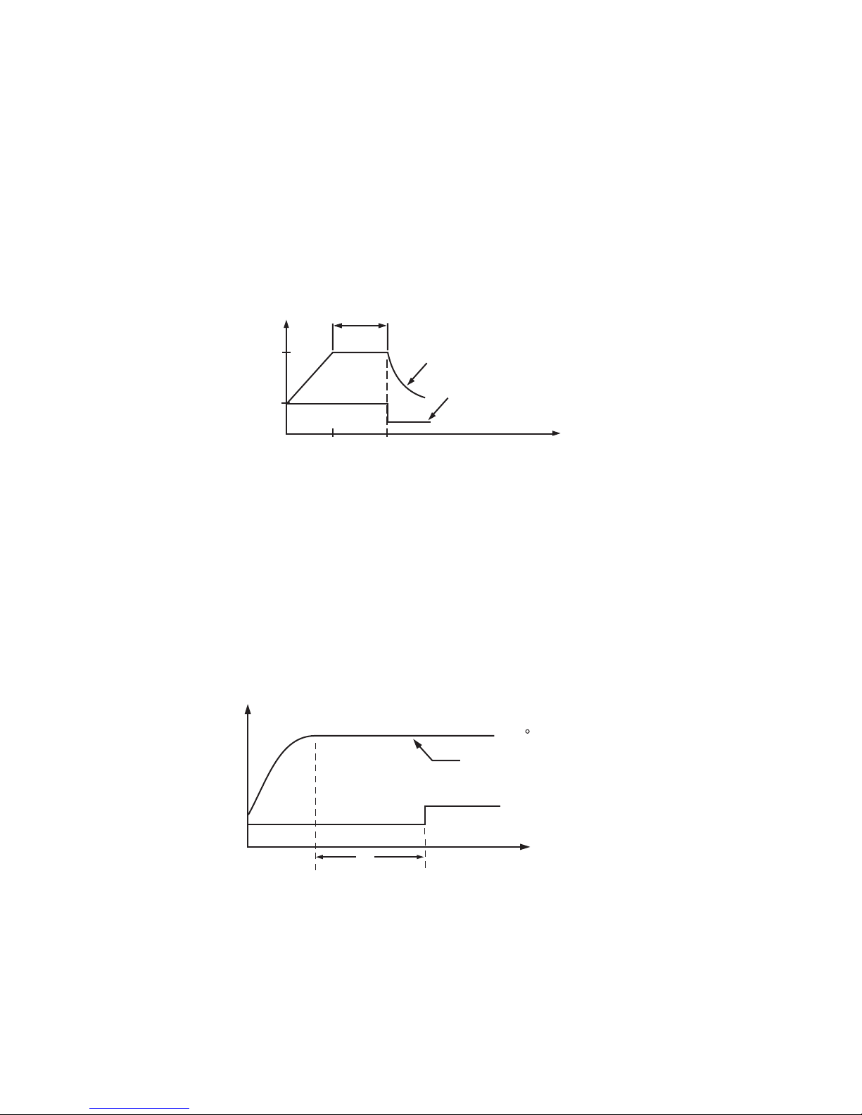
In the example below, RAMP is set for 5.00°F/minute, A1SF=TOOF, and ASP1=40 (minutes). Power is applied at zero
time, and the process climbs from the ambient temperature of 50°F to the set point of 200°F over 30 minutes. The dwell
timer is activated upon reaching the set point and, after the soak time of 40 minutes, the alarm 1 relay will open,
switching off the output. The process temperature will then fall at an undetermined rate.
Dwell Function
The dwell function is enabled by configuring alarm 1 to act as a dwell timer. If A1SF is set to TOON (time out on), the
alarm 1 relay will operate as a timer contact with the contact being open on initial start up. The timer begins to count
down once the set point temperature has been reached. After the amount of time set in ASP1 has elapsed, the alarm 1
relay will close. This function can be used to operate an external device such as a siren or a light (for example) to alert
the operator when a minimum desired soak time has been reached.
In the example below, the ramp rate has been set to zero, A1SF=TOON, and ASP1=40 (minutes). Initial start up is at
zero time, and the process climbs to the 200°F set point at the maximum rate. Once the set point is reached, the dwell
timer begins to count. After 40 minutes, the alarm 1 relay closes. The controller will continue to act as a fixed set point
controller.
5–14 Re-ranging Linear Process Inputs
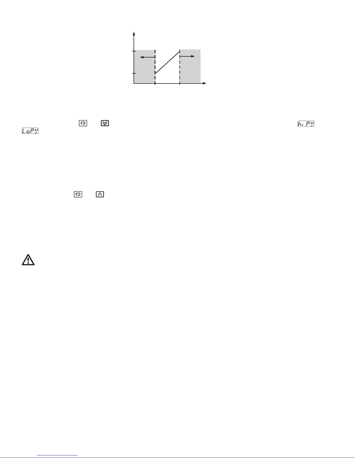
Select an appropriate input type (INPT). Define the range by adjusting LOSC and HISC. In the example below,
INPT=4–20 (mA), LOSC=0, HISC=100.0, and RESO=1DP. For a 4mA input, the process value will read 0 (LOSC), and
for a 20mA input, the process value will read 100.0 (HISC). For a 10mA input, the process value will read 37.5. If the
input signal is outside of the range defined by LOSC and HISC, an error message (LLEr or HLEr) will be shown in the
upper display.
21
40
∞F
minutes
200
50
30
ON
70
Process value
Alarm 1 output
OFF
Time
(minutes)
∞F
200 F
PV
Alarm 1 OFF
40
minutes
Alarm 1 ON
Time (minutes)
Page 22
5–15 Read Peak Process Values
The maximum and minimum values of the process value are continuously updated and stored in the memory after
power up. Press both and to access the “READ PEAK” tool program. Press the scroll key to select or
in the lower display. The upper display will now show the high peak value or low peak value of the process,
respectively.
To reset the peak values, press and hold the scroll key for 3.2 seconds, then release. Both the low and high peak values
will now be revised by the current process value.
5–16 Lock/Unlock Parameters
• Lock all of the parameters
Press and hold both and for 3.2 seconds, then release. Keypad operation is now disabled to protect the
parameters from tampering. To unlock the keypad, press and release the up and down keys.
• Lock all parameters in a given security level
Refer to “LOCK Parameter” in section 5–5.
6. Recalibration
Do not proceed through this section unless there is a definite need to recalibrate the controller. All previous
calibration data will be lost. Do not attempt recalibration unless you have the appropriate calibration equipment available.
If the calibration data is lost, you will need to return the controller to your supplier who may charge you a service fee to
recalibrate the controller.
• Equipment needed
1. Standard millivolt source with a range of 0–100mV with accuracy of ±0.01%.
2. Standard voltage source with a range of 0–10V with accuracy of ±0.01%.
3. Standard current source with a range of 0–20mA with accuracy of ±0.01%.
4. Standard ohm source with a range of 0–300 ohms with accuracy of ±0.01%.
5. Standard thermometer with a range of 32–122°F (0–50°C) with accuracy of ±0.36°F (±0.2°C).
6. A cooling fan or, ideally, a calibration fixture equipped with a fan and a push-button switch.
7. Thermocouple simulator.
• Calibration setup:
1. Select T/C input, UNIT=°F, RESO=1DP
2. Switch the power off
3. Disconnect the sensor wiring
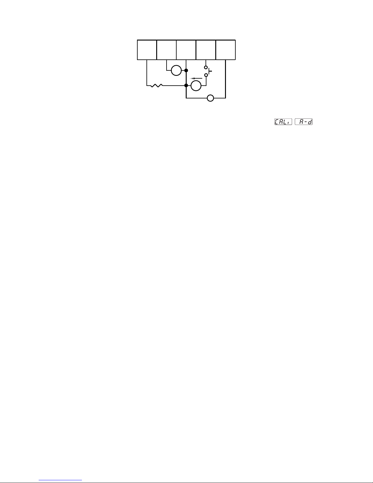
4. Connect the input terminals of the controller to the signal sources according to the following diagram
5. Install a fan to blow on the cold-junction compensator located at the rear edge of the lower PCB to prevent it from
warming up.
22
PV
100.0
(HISC)
LLEr
0
(LOSC)
4
20
HLEr
Input signal (mA)
Page 23
• Calibration procedures
1. Press both scroll and down keys, then release to access the tool programs. Repeat until appears on
the displays.
2. Press and release the scroll key. The lower display will show a number with the prefix “t”.
3. Use the up and down keys to change the value of the lower display until it matches the ambient temperature in °F
as measured by the standard thermometer.
4. Press the scroll key for at least 3.2 seconds, then release. The upper display will blink for a moment and then show
the ambient temperature in °F.
5. Press and release the scroll key. The lower display will show a number with the prefix “A”, and the upper display will
show 0.00.
6. Press and hold down push-button switch SW1 from the diagram above. While holding down SW1, Press and hold
the scroll key for at least 3.2 seconds, then release. The upper display will now show 20.00. Release SW1.
7. Press and release the scroll key. The lower display will show a number with the prefix “d”. If the number is not 0.0,
use the up and down keys to set it to 0.0, then press the scroll key for at least 3.2 seconds, then release.
• Verify calibration accuracy
1. Repeat step 1 from the calibration procedures as described above.
2. Press and release the scroll key until an “A” code is shown in the display. The display will indicate process value
with respect to the 0–20mA input. Feed a standard signal to the correct mA input terminals and examine the
accuracy of the display.
3. Press and release the scroll key again until a “d” code is shown in the display. Now the display will indicate process
value with respect to the INPT type selected. Feed a standard signal to the appropriate input terminals and examine
the accuracy of the display.
4. Press the scroll and up keys, then release quickly. The display will indicate process value with respect to the
PT100/DIN input. Feed a standard signal to the PT100 input terminals and examine the accuracy of the display.
5. Press the scroll and up keys, then release quickly. The display will indicate process value with respect to the 0–10V
input. Feed a standard signal to the voltage input terminals and examine the accuracy of the display.
• Warm-up drift correction for thermocouple input. After completing the calibration procedures above, connect a
thermocouple to terminals 13 and 14 (observing polarity) and select the correct INPT for the thermocouple. Switch the
power on and leave it on for at least 30 minutes. If the controller does not measure the correct temperature for the
thermocouple, the following procedures may be used to correct the error.
1. Perform steps 1 and 2 from the calibration procedures.
2. Press and release the scroll key.
3. Press and release the scroll key again. Now the “d” code with zero value will show on the display.
4. Use the up and down keys to change the “d” code value until the upper display shows the correct temperature. The
“d” code is always shown in °C, regardless of the setting of the UNIT parameter.
5. Press the scroll key for at least 3.2 seconds, then release. The upper display will blink for a moment, then show an
accurate temperature. If the accuracy of the controller is still unsatisfactory, replace the controller.
23
PTA
TC-
COM+
mA- V-
+
1615
SW1
-
10V
12
13
200 ohm
14
- +
40mV
20mA
Page 24
7. Error Messages and Diagnosis
This procedure requires access to the circuitry of a unit connected to live power. Dangerous accidental contact
with line voltage is possible. Only qualified personnel are to perform these procedures. Potentially lethal voltages are
present.
Experience has proven that many control problems are not caused by a defective instrument. See the chart below and
table 7.1 for some of the other common causes of failures.
• Line wires are improperly connected
• No voltage between line terminals
• Incorrect voltage between line terminals
• Connections to terminals are open, loose, or missing
• Thermocouple is open at tip
• Thermocouple lead is broken
• Shorted thermocouple leads
• Short across terminals
• Open or shorted heater circuit
• Open coil in external contactor
• Burned out line fuses
• Burned out relay inside control
• Defective solid-state relays
• Defective line switches
• Burned out contactor
• Defective circuit breakers
If the points listed on the chart have been checked and the controller still does not function, it is suggested that the
instrument be returned for inspection. Do not attempt to make repairs. Be sure to use adequate packing materials to
prevent damage during shipment.
24
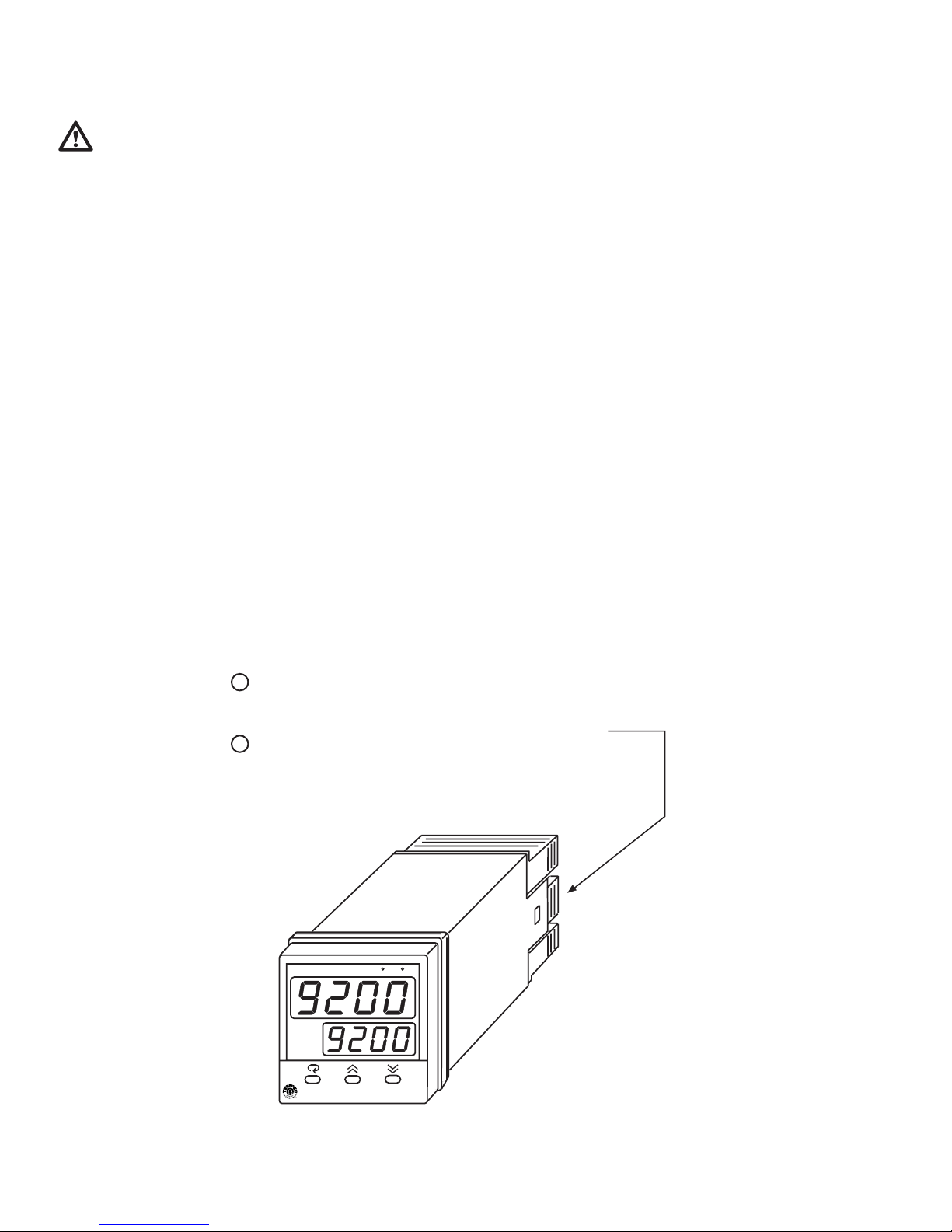
Press both sides of the latch located on rear
block from the housing.
Expand the rear edge of the housing by
using a tool. Pull out the PCB from the housing.
-9200
1
Press both sides of the latch located on rear
terminal block. Hold tightly and remove the terminal
block from the housing.
Expand the rear edge of the housing by
2
using a tool. Pull out the PCB from the housing.
Dismantling the Controller
A1
A2 PV FC
SV
OUT
TEC
-9300
Page 25
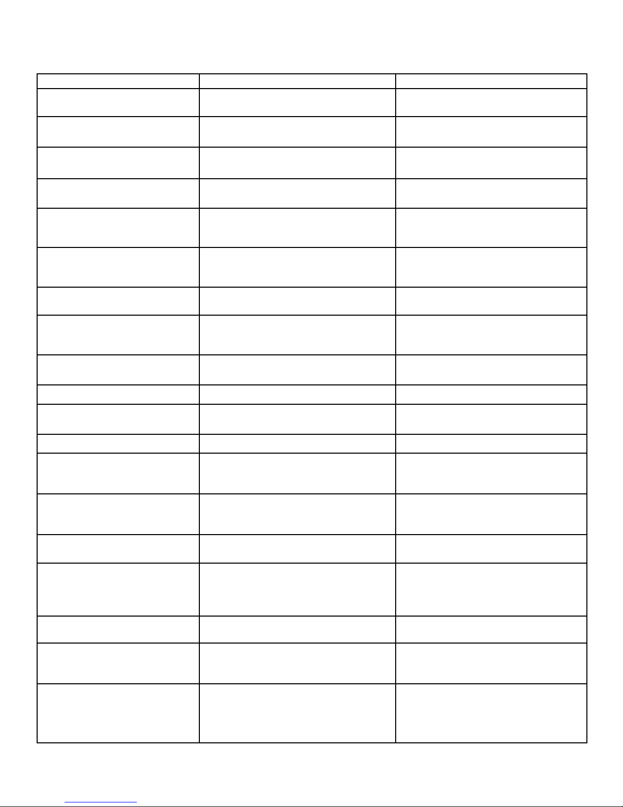
Table 7.1 Troubleshooting
Symptom Probable Cause(s) Solution(s)
1. Keypad doesn’t function -Bad connection between PCB and keypads -Clean contact area on PCB
-Replace keypads
2. LEDs will not light -No power to instrument
-Power supply defective
-Check power line connections
-Replace power supply board
3. Some segments of the display or
LED lamps not lit or lit erroneously
-LED display or LED lamp defective
-Related LED driver defective
-Replace LED display or LED lamp
-Replace the related transistor or IC chip
4. Process display shows: SBER -Sensor break error -Replace RTD or sensor
-Use manual mode operation
5. Process display shows: LLER -Input signal beyond the low range, sensor fails
-Incorrect input type selected
-Replace sensor
-Check sensor or thermocouple type, correct
input selection
6.Process display shows: HLER -Input signal beyond the high range, sensor fails
-Incorrect input type selected
-Replace sensor
-Check sensor or thermocouple type, correct
input selection
7. Process display shows: ADER -A to D module damage -Replace module. Check for outside source of
damage such as transient voltage spikes.
8. Process display shows: OPER -Incorrect operation of autotune
-Set point for autotune too low
-Manual mode does not allow on-off control
-Set P band greater than 0, repeat procedure
-Increase set point
-Increase proportional band
9. Process display shows: CSER -Check sum error, values in memory may have
changed accidentally
-Check and reconfigure the control
parameters
10. Process display shows: NTER -Data failed to be entered into EEPROM -Replace EEPROM
11. Process display shows: OVER -Overflow error, data out of range during
execution of software program
-Check for electrical noise
12. Process display shows: LOCK -Attempt to change a locked parameter -Unlock parameter (see section 5–16)
13. Display unstable -Analog portion or A-D converter defective
-Thermocouple, RTD, or sensor defective
-Intermittent connection of sensor wiring
-Replace related components or board
-Check thermocouple, RTD, or sensor
-Check sensor wiring connections
14. Considerable error in temperature
indication
-Wrong sensor or thermocouple type/wrong
input mode selected
-Analog portion or A-D converter defective
-Check sensor or thermocouple type and if
proper input mode was selected
-Replace related components or board
15. Display goes in reverse direction
(counts down scale as process warms)
-Reversed input wiring of sensor -Check and correct
16. No heat or output -No heater power (output), incorrect output
device used
-Output device defective
-Open fuse outside of the instrument
-Check output wiring and output device
-Replace output device
-Replace output fuse
17. Heat or output stays on but
indicator reads normal
-Output device or power source shorted -Check and replace
18. Control abnormal or operation
incorrect
-CPU or EEPROM (non-volatile memory)
defective. Key switch defective
-Operation of control incorrect
-Check and replace
-Read the operation procedure carefully
19. Display blinks, entered values
change by themselves
-Electromagnetic interference (EMI), or Radio
Frequency interface (RFI)
-EEPROM defective
-Suppress arcing contacts in system to
eliminate high voltage spike sources.
Separate sensor and controller wiring from
“dirty” power lines. Ground heaters
-Replace EEPROM
25
Page 26

26
TEMPCO Electric Heater Corporation
607 N. Central Avenue
Wood Dale, IL 60191-1452 USA
Tel: 630-350-2252
800-323-6859
Fax: 630-350-0232
website: http://www.tempco.com
Copyright © 2003, Tempco Electric Heater Corporation, all rights reserved.
 Loading...