

Page 1

Instruction Manual
TEC-9090
Self-Tune Fuzzy / PID Process
Process Temperature Controller
Serving Industry Since 1972
TEMPCO Electric Heater Corporation
607 N. Central Avenue • Wood Dale, IL 60191-1452 USA
Tel: 630-350-2252 • Toll Free: 800-323-6859
Fax: 630-350-0232 • E-mail: [email protected]
Web: www.tempco.com
Manual TEC-9090 Revision 10/2014
Page 2

NOTES
Page 3

NOTE:
It is strongly recommended that a process should
incorporate a LIMIT CONTROL like TEC-910
which will shut down the equipment at a preset
process condition in order to preclude possible
damage to products or system.
Information in this user's manual is subject to change
without notice.
Contents
Page No.
Chapter 1 Introduction 1
Chapter 2 Ordering Code 2
Chapter 3 Front Panel Description 3
Chapter 4 Input Range & Accuracy 3
Chapter 5 Specifications 4
Chapter 6 Installation
6-1 Dimensions and Panel Cutout 5
6-2 Wiring Diagram 5
Chapter 7 Calibration 6
Chapter 8 Operation
8-1 Keypad Operation 6
8-2 Flow Chart 7
8-3 Parameter Description 7
8-4 Automatic Tuning 8
8-5 Manual PID Adjustment 8
8-6 Manual Tuning Procedure 9
8-7 Ramp and Dwell 9
Copyright © 2014, Tempco Electric Heater
Corporation, all rights reserved. No part of this publication may be reproduced, transmitted, transcribed or
stored in a retrieval system, or translated into any language in any form by any means without the written
permission of Tempco Electric Heater Corporation.
Figures & Tables
Page No.
Figure 1.1 Fuzzy Control Advantage 1
Figure 3.1 Front Panel Description 3
Figure 6.1 Mounting Dimensions & Panel Cutout 5
Figure 6.2 Wiring Diagram 5
Figure 8.1 Manual Tuning Procedure 8
Figure 8.2 Ramp and Dwell Example 10
Table A.1 Error Codes and Corrective Actions 11
Appendix
Warranty 11
Returns 11
Page 4

NOTES
Page 5
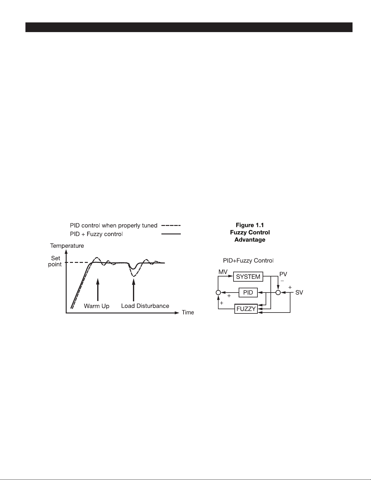
Chapter 1 Introduction
This manual contains information for the installation
and operation of the Tempco model TEC-9090 fuzzy
logic microprocessor based controller.
Fuzzy logic is an essential feature of this versatile
controller. Although PID control has been widely
accepted by many industries, it is difficult for PID
control to work efficiently with some sophisticated
systems, such as second order systems, systems with
long time-lag, varying set points, varying loads, etc.
Because of the disadvantages of the controlling principles and fixed values of PID control, it is inefficient
when controlling systems with a lot of variables, and
the result is below expectations for some systems.
Fuzzy logic control can overcome these disadvantages of PID control. The function of fuzzy logic is to
adjust the PID values indirectly in order to make the
manipulation of output value MV adapt flexibly and
quickly to varying processes. In this way, it enables a
process to reach its predetermined set point in the
shortest amount of time with minimum overshooting
during tuning or external disturbance. Unlike PID
control which uses digital information, fuzzy logic
uses language information.
In addition, this instrument has the functions of single
stage ramp and dwell, auto-tuning, and manual mode
execution. It is also easy to use.
1
Page 6
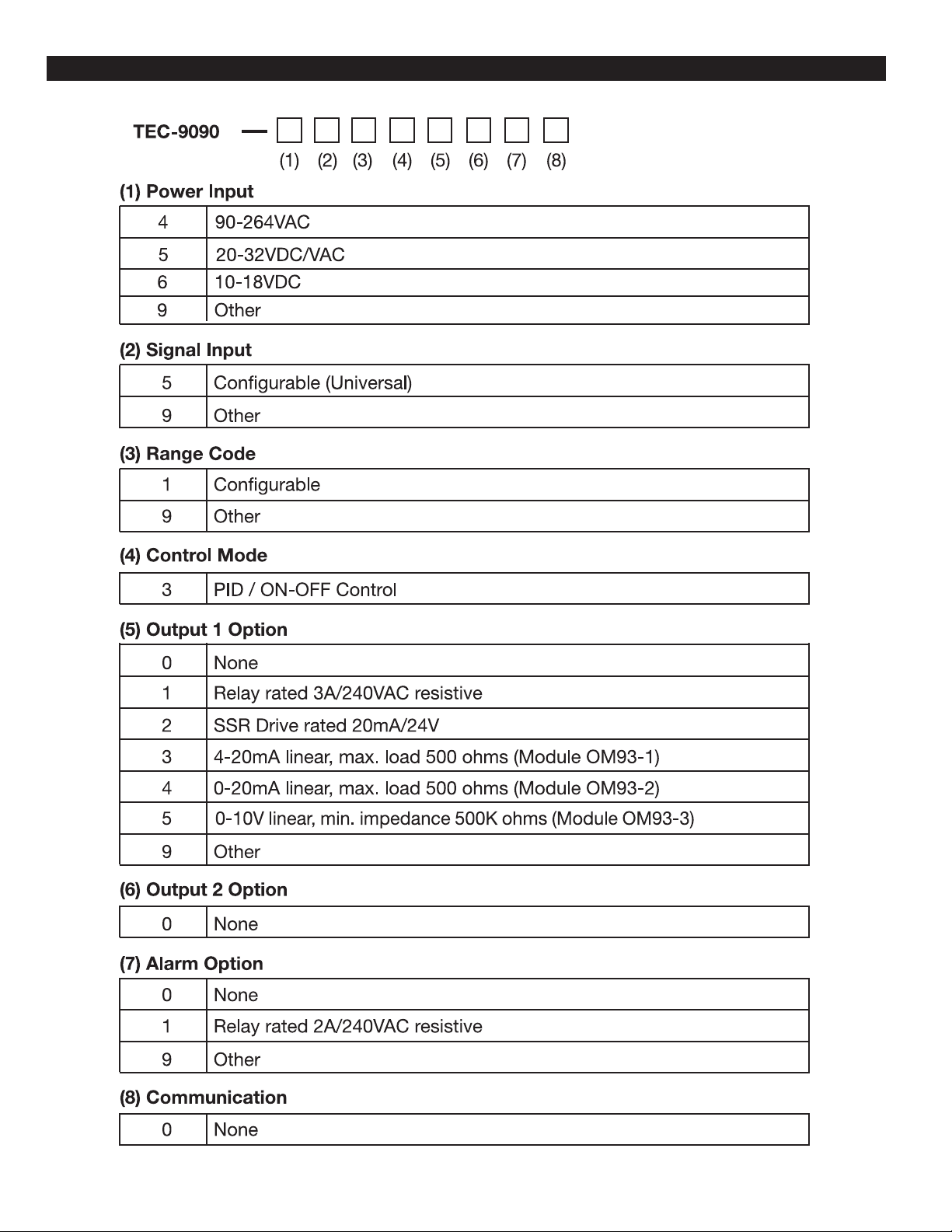
Chapter 2 Ordering Code
2
Page 7

Chapter 3 Front Panel Description
Figure 3.1
Front Panel Description
Chapter 4 Input Range and Accuracy
Sensor Input Type Range (°F) Accuracy (°F) Range (°C) Accuracy (°C)
J Iron/Constantan -58 to 1832°F ±3.6°F -50 to 1000°C ±2°C
K Chromel/Alumel -58 to 2500°F ±3.6°F -50 to 1370°C ±2°C
T Copper/Constantan -454 to 752°F ±3.6°F -270 to 400°C ±2°C
E Chromel/Constantan -58 to 1382°F ±3.6°F -50 to 750°C ±2°C
B Pt30%RH/Pt6%RH 32 to 3272°F ±5.4°F 0 to 1800°C ±2°C
R Pt13%RH/Pt 32 to 3182°F ±3.6°F 0 to 1750°C ±2°C
S Pt10%RH/Pt 32 to 3182°F ±3.6°F 0 to 1750°C ±2°C
N Nicrosil/Nisil -58 to 2372°F ±3.6°F -50 to 1300°C ±2°C
RTD PT 100 ohms (DIN) -328 to 752°F ±0.72°F -200 to 400°C ±0.4°C
RTD PT 100 ohms (JIS) -328 to 752°F ±0.72°F -200 to 400°C ±0.4°C
Linear Voltage or Current -1999 to 9999 ±.05% -1999 to 9999 ±.05%
3
Page 8

Chapter 5 Specifications
Input
Thermocouple (T/C): type J, K, T, E, B, R, S, N.
RTD: PT100ohm RTD (DIN 43760/BS1904 or JIS)
Linear: -10 to 60mV, configurable input attenuation
Range: User configurable, refer to table above
Accuracy: Refer to table above
Cold junction compensation: 0.1°F/°F ambient typical
Sensor break protection: Protection mode configurable
External resistance: 100ohms max.
Normal mode rejection: 60dB
Common mode rejection: 120dB
Sample rate: 3 times/second
Control
Proportion band: 0–360°F (0–200°C)
Reset (integral): 0–3600 seconds
Rate (derivative): 0–1000 seconds
Ramp rate: 0–360.0°F/minute (0–200.0°C/minute)
Dwell: 0–3600 minutes
ON-OFF: With adjustable hysteresis (0–20% of SPAN)
Cycle time: 0–120 seconds
Control action: Direct (for cooling) and reverse (for heating)
Power
Rating: 90–264VAC, 50/60Hz or low voltage (note label)
Consumption: Less than 5VA
Environmental and Physical
Safety: UL873, CSA22.2/142-87, IEC1010-1 (EN61010-1)
EMC emission: EN50081-1
EMC immunity: EN50082-2
Operating temperature: 14–122°F (-10 to 50°C)
Humidity: 0 to 90% RH (non-condensing)
Insulation: 20Mohms min. (500VDC)
Breakdown: AC 2000V, 50/60Hz, 1 minute
Vibration: 10–55 Hz, amplitude 1mm
Shock: 200m/s (20g)
Net weight: 170 grams
Housing materials: Poly-carbonate plastic
4
Page 9
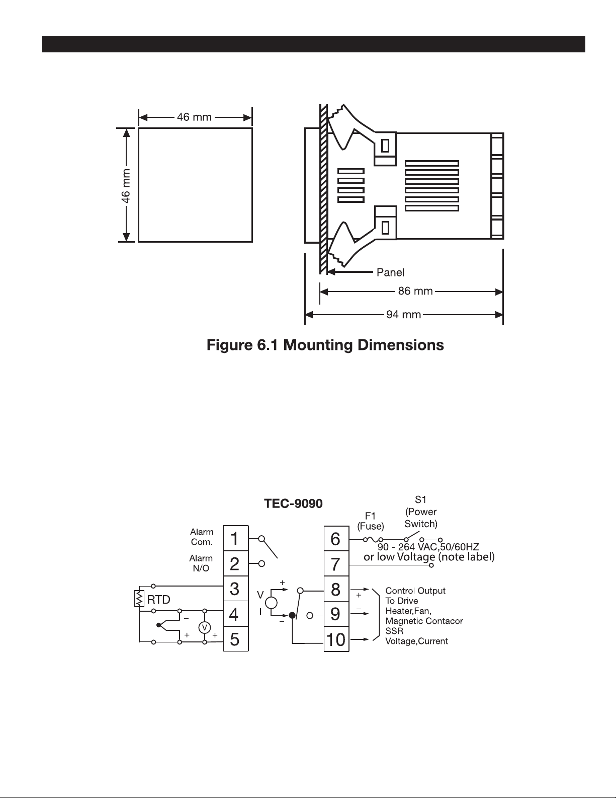
Chapter 6 Installation
6–1 Dimensions and Panel Cutout
6–2 Wiring Diagram
Figure 6.2 Wiring Diagram
5
Page 10

Chapter 7 Calibration
Note: Do not proceed through this section unless
there is a genuine need to recalibrate the controller.
All previous calibration data will be lost. Do not
attempt recalibration unless you have the appropriate
calibration equipment available. If the calibration
data is lost, you will need to return the controller to
your supplier who may charge a service fee for recalibration.
Prior to calibration, ensure that all parameter settings
are correct (input type, °C /°F, resolution, low range,
high range).
1. Remove the sensor input wiring and connect a
standard input simulator of the correct type to the
controller input. Verify that the polarity is correct.
Set the simulated signal to coincide with the low
process signal (e.g., zero degrees).
2. Use the scroll key until " " appears on the
PV display. (Refer to 8.2)
3. Use the up and down keys until the SV display represents the simulated input.
4. Press the return key for at least 6 seconds (maximum 16 seconds), then release. This enters the low
calibration figure into the controller's non-volatile
memory.
5. Press and release the scroll key. " " appears
on the PV display. This indicates the high calibration point.
6. Increase the simulated input signal to coincide with
the high process signal (e.g., 100 degrees).
7. Use the up and down keys until the SV display represents the simulated high input.
8. Press the return key for at least 6 seconds (maximum 16 seconds), then release. This enters the
high calibration figure into the controller's nonvolatile memory.
9. Turn off power to the unit, remove all test wiring
and replace the sensor wiring (observing polarity).
Chapter 8 Operation
8–1 Keypad Operation
*With power on, it takes 12 seconds to memorize the new values of parameters once they have been changed.
6
Page 11
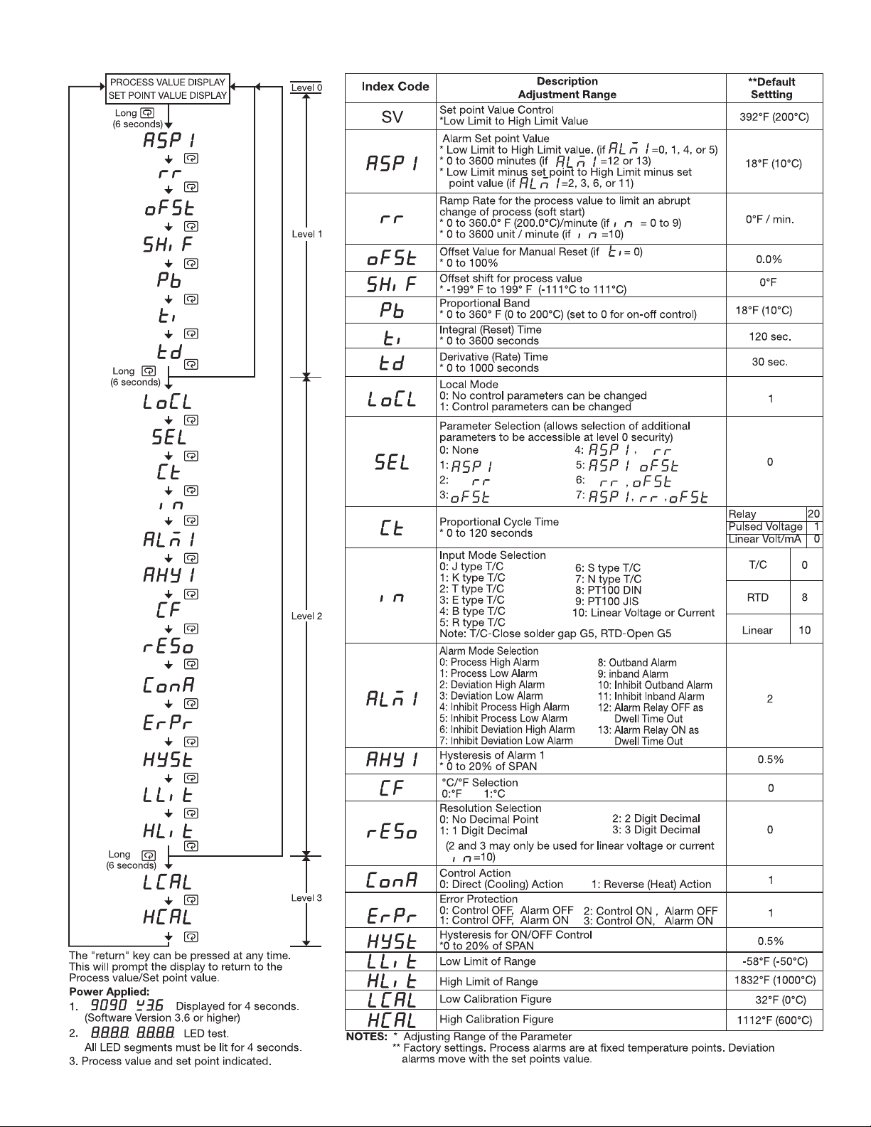
8–2 Flow Chart 8–3 Parameter Description
7
Page 12

8–4 Automatic Tuning
1. Ensure that the controller is correctly configured
and installed.
2. Ensure that the proportional band “PB” is not set at
“0”.
3. Press the return key for at least 6 seconds (maximum 16 seconds). This initializes the auto-tune
function. (To abort auto-tuning procedure, press
and release the return key).
4. The decimal point in the lower right hand corner of
the PV display flashes to indicate that auto-tuning
is in progress. Auto-tune is complete when the
flashing stops.
8–5 Manual PID Adjustment
Although the auto-tuning function will select control
settings which should prove satisfactory for the
majority of processes, you may find it necessary to
make adjustments to these settings from time to time.
This may be the case if some changes are made to the
process or if you wish to fine-tune the control settings.
5. Depending on the particular process, automatic
tuning may take up to two hours. Processes with
long time lags will take the longest to tune.
Remember, while the display point flashes, the
controller is auto-tuning.
NOTE: If an AT error( ) occurs, the automatic tuning process is aborted due to the system operating in ON-OFF control mode (PB=0). The process
will also be aborted if the set point is set too close to
the process temperature or if there is insufficient
capacity in the system to reach the set point (e.g.,
inadequate heating power available). Upon completion of auto-tuning, the new PID settings are automatically entered into the controller's non-volatile
memory.
It is important, prior to making changes to the control
settings, that you record the current settings for future
reference. Make only slight changes to one setting at
a time and observe the results on the process. Because
each of the settings interacts with the others, it is easy
to become confused with the results if you are not
familiar with process control procedures.
Tuning Guide
Proportional Band
Symptom Solution
Slow Response Decrease PB Value
High Overshoot or Oscillations Increase PB Value
Integral Time (Reset)
Symptom Solution
Slow Response Decrease Integral Time
Instability or Oscillations Increase Integral Time
Derivative Time (Rate)
Symptom Solution
Slow Response or Oscillations Decrease Derivative. Time
High Overshoot Increase Derivative Time
8
Page 13
8–6 Manual Tuning Procedure
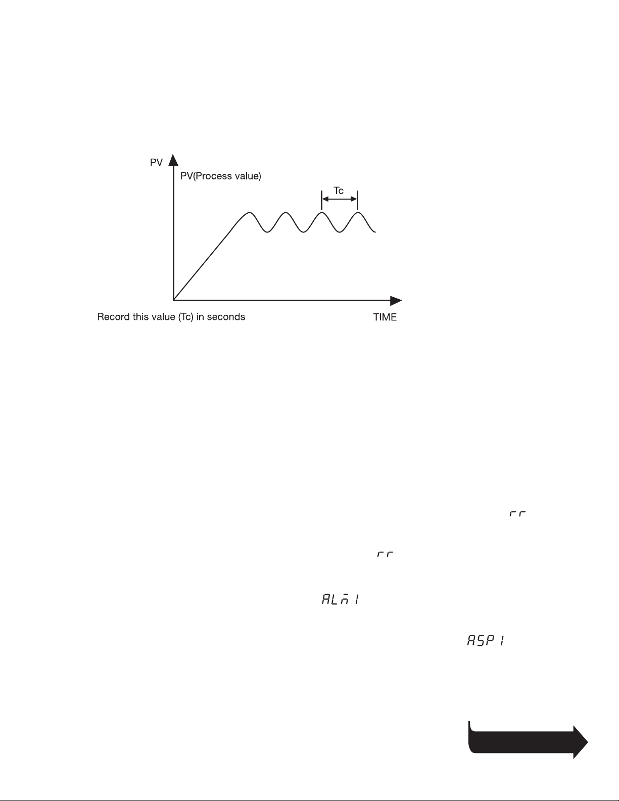
Step 1: Adjust the integral and derivative values to 0. This inhibits the rate and reset action
Step 2: Set an arbitrary value for proportional band and monitor the control results
Step 3: If the original setting introduces a large process oscillation, then gradually increase the
proportional band until steady cycling occurs. Record this proportional band value (Pc).
Step 4: Measure the period of steady cycling
Figure 8.1
Manual Tuning Process
Step 5: The control settings are determined as follows:
Proportion band (PB)=1.7 Pc
Integral time (TI)=0.5 Tc
Derivative time (TD)=0.125 Tc
8–7 Ramp and Dwell
The TEC-9090 controller can be configured to act as
either a fixed set point controller or as a single ramp
controller on power up. This function enables the user
to set a pre-determined ramp rate to allow the process
to gradually reach the set point temperature, thus producing a “soft start” function.
A dwell timer is incorporated within the TEC-9090 and
the alarm relay can be configured to allow the dwell
function to be used in conjunction with the ramp function.
The ramp rate is determined by the “ ” parameter
which can be adjusted within the range of 0 to
200.0°C/minute. The ramp rate function is disabled
when the “ ” parameter is set to “0”.
The soak function is enabled by configuring the alarm
output to act as a dwell timer. The parameter
needs to be set with a value of 12. The alarm
contact will now operate as a timer contact, with the
contact closed at power up and opening after the
elapsed time set in parameter .
If the controller power supply or output is wired
through the alarm contact, the controller will operate as
a guaranteed soak controller.
continued…
9
Page 14
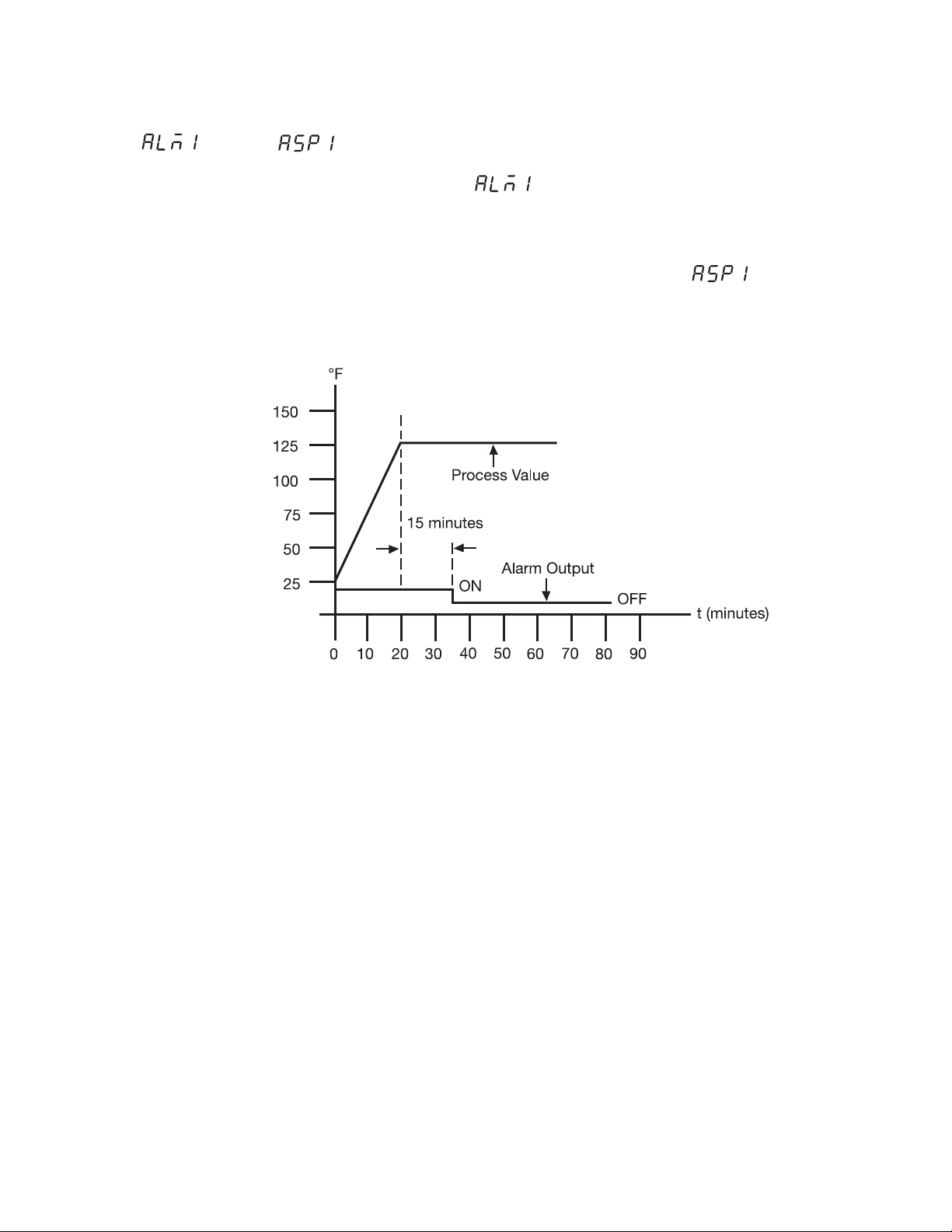
In the example below, the ramp rate is set at
5°F/minute, =12 and =15 (minutes).
Power is applied at zero time and the process climbs at
5°F/minute to the set point of 125°F. Upon reaching
the set point, the dwell timer is activated, and after the
soak time of 15 minutes, the alarm contact will open,
switching off the output. The process temperature will
eventually fall at an undetermined rate.
The dwell function may also be used to operate an
external device such as a siren to alert when a soak
time has been reached.
needs to be set with a value of 13. The alarm
contact will now operate as a timer contact, with the
contact being open on the initial start up. The timer
begins to count down once the set point temperature is
reached. After the setting at has elapsed, the
alarm contact closes.
Figure 8.2
Ramp and Dwell
10
Page 15
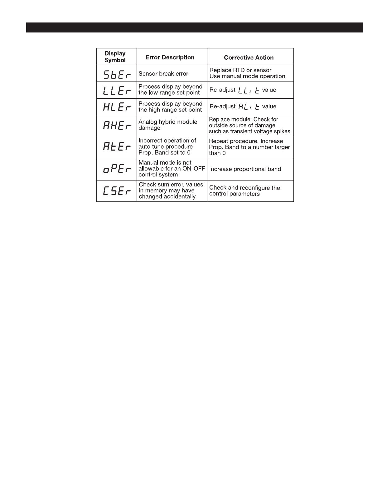
Chapter 9 Error Messages
WARRANTY
Tempco Electric Heater Corporation is pleased to offer suggestions on the use of its products. However, Tempco
makes no warranties or representations of any sort regarding the fitness for use, or the application of its products by
the Purchaser. The selection, application, or use of Tempco
products is the Purchaser's responsibility. No claims will be
allowed for any damages or losses, whether direct, indirect,
incidental, special, or consequential. Specifications are subject to change without notice. In addition, Tempco reserves
the right to make changes–without notification to the
Purchaser–to materials or processing that do not affect
compliance with any applicable specification. TEC
Temperature Controllers are warranted to be free from
defects in material and workmanship for two (2) years after
delivery to the first purchaser for use. Tempco's sole
responsibility under this warranty, at Tempco's option, is
limited to replacement or repair, free of charge, or refund of
purchase price within the warranty period specified. This
warranty does not apply to damage resulting from transportation, alteration, misuse, or abuse.
RETURNS
No product returns can be accepted without a completed
Return Material Authorization (RMA) form.
TECHNICAL SUPPORT
Technical questions and troubleshooting help is available
from Tempco. When calling or writing please give as much
background information on the application or process as
possible.
E-mail: [email protected]
Phone: 630-350-2252
800-323-6859
11
Page 16

Complete Your Thermal Loop System
With Over 100,000 Various Items
Available from Stock
• Electric Heating Elements
• Thermocouples and RTD Assemblies
• SCR Power Controls
• Solid State Relays
• Mechanical Relays
• Videographic Data Recorders
• Temperature Measurement
• Current Indicators
• Thermocouple and Power Lead Wire
• Wiring Accessories
™
TEMPCO’s Visionary Solutions
The Electric Heating Element, Temperature Controls and
Temperature Sensors Handbook
REQUEST YOUR FREE 960 PAGE COPY TODAY!
Call (800-323-6859) or E-mail ([email protected])
Specify Print Edition, CD-ROM or Both
Serving Industry Since 1972
Experience the Advantages of our Diverse and Innovative Products
TEMPCO Electric Heater Corporation
607 N. Central Avenue • Wood Dale, IL 60191-1452 USA
Tel: 630-350-2252 • Toll Free: 800-323-6859
Fax: 630-350-0232 • E-mail: [email protected]
Web: www.tempco.com
© Copyright 2014 TEHC. All Rights Reserved.
1P250L13
 Loading...