

Page 1

Tempco Instruction Manual
1/8 DIN Solid State Temperature Controller– Relay
Output–Solid State Output–For Heating
TEC-805
The TEC-805 is designed to fit panel cutouts that are 1.781" (45mm) x 3.625" (92mm).
3" minimum depth is required to provide clearance for rear terminal connections.
Input
Thermocouple (T/C) Type K, J. See Control label.
RTD 3-wire PT100 DIN or JIS
Cold junction compensation Automatic
Input break protection Built-in, upscale on open sensor and output off
Input impedance 10M ohm
Common mode rejection (CMR) CMRR 120dB, min.
Normal mode rejection (NMR) NMRR 60dB, min. (60Hz)
Control Output
Relay—heating SPDT relay, 5 amps max resistive load at 120V, 240VAC, or 24VDC
Optional:
20VDC For output to solid state relay
4–20mA For output to SCR
Relay—alarm SPST relay, 2 amps max resistive load at 120V or 240VAC
Control Modes
On-Off Differential 0.5% of full-scale range
Proportional Proportional Band fixed at 2.5% of range. Proportional Cycle time 20 seconds
for relay controls, 1 second for SSR controls
Indication
Output Red LED lit, heater on/LED not lit, heater off.
Set Point
Resolution ±1 Least significant digit
Accuracy ±1% of span
Repeatability ±1 significant digit
Manual Reset Adjustable up to 2.6% of span
Power
Rating 90–264VAC, 50/60Hz.
24VAC/DC models can be special ordered.
Consumption Less than 3VA.
Environmental and Physical
Operating Temperature 32–122°F (0–50°C)
Humidity 0–90% RH (non-condensing)
Insulation 20M ohm min. (500VDC)
Breakdown 2000VAC, 50/60Hz, 1 minute
Vibration 10–55Hz, amplitude 1.0mm
Shock 660ft/s≈ (20g)
Weight 8oz. (227g)
Dimensions
Height: 3.75" (96mm) x Width: 1.875" (48mm) x Depth: 3.125" (80mm)
Depth behind panel: 2.559" (65mm)
Panel cutout 1.871" x 3.625" (46mm x 92mm)
DIN case Plastic full plug-in construction with screw terminals on rear and adjustable
brackets for panel mounting.
Revision 9/2016
Page 1 of 4
Page 2
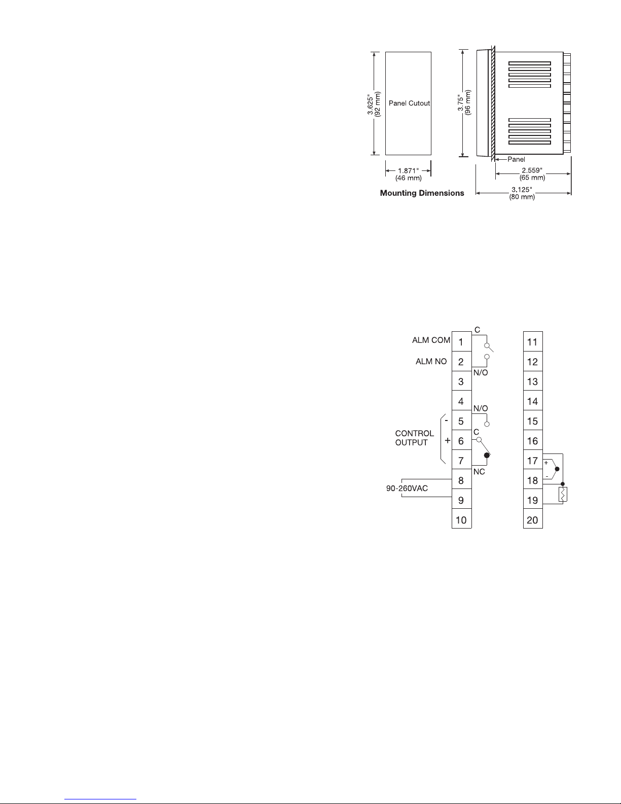
Mounting
When mounting one of these instruments, make sure the control and
the ambient temperature remain within the 10–125°F range. The
control may be mounted in any position. Once the control has been
inserted into the panel, use the two mounting brackets provided with
the unit to secure it. Use light to moderate pressure.
Manual Reset Adjustment
The reset adjustment is located on the front of the control.
Approximately half an hour after adjusting the set point, when the
process stabilizes, it may become necessary to adjust “reset” as well.
Start with the reset adjustment pointing to zero. If the temperature
indication stabilizes above the set point, adjust the reset to the
“minus” side; if the temperature stabilizes below the set point, adjust
to the “plus” side. Continue making adjustments until the temperature
indication stabilizes at the set point. Make sure to allow 15 minutes
between adjustments for stabilization.
Wiring
All wiring should conform to local and national codes.
When wiring the thermocouple, make sure that the thermocouple and
extension wire conform to the thermocouple type specified by the
instrument. The thermocouple and the extension wires must have the
same polarity and be the same alloy. For accurate measurements, the
total lead resistance should not exceed 100 ohms.
To assure effective lead resistance compensation when wiring three
wire RTDs (Resistance Temperature Detectors), make sure that all of
the leads that connect to the controller are the same gauge and
composition. Connect the two common wires of the three wire RTD to
terminals 17 and 18. When using a two wire RTD, install a jumper
between terminals 17 and 18.
WARNINGS
1. Dangerous voltages may be present in these
instruments. Before installation or troubleshooting,
switch off and isolate power to all equipment. If a unit
is suspected of being faulty, it should be disconnected
and removed to a properly equipped workshop for
testing and repair. Component replacement and
internal adjustments should be performed by qualified
maintenance personnel only.
2. To minimize the risk of fire or shock hazards, avoid
exposing these instruments to rain or excessive
moisture.
3. Do not use these instruments in areas that are prone to
hazardous conditions such as excessive shock,
vibration, dirt, moisture, corrosive gases, or oil. The
ambient temperature of the areas should not exceed
the maximum rating specified.
Page 2 of 4
Page 3

Wiring Precautions:
• Before wiring, verify the correct model number and
options on the label. Switch off the power while
checking.
• Care must be taken to ensure that the maximum voltage
rating specified on the label is not exceeded.
• It is recommended that the power for these units be
protected by fuses or circuit breakers rated at the
minimum value possible.
• All units should be installed in a suitable enclosure to
prevent live parts from being accessible to human hands
and metal tools. Metal enclosures and/or subpanels
should be grounded in accordance with national and
local codes.
• All wiring must conform to appropriate standards of
good practice and local codes and regulations. Wiring
must be suitable for the voltage, current, and
temperature rating of the system.
• Beware not to over-tighten the terminal screws. The
torque should not exceed 1 N-m (8.9 lb-in or 10 KgF-cm).
• Unused control terminals should not be used as jumper
points as they may be internally connected, causing
damage to the unit.
• Verify that the ratings of the output devices and the
inputs as specified are not exceeded.
• Except for thermocouple wiring, all wiring should use
stranded copper conductor with a maximum gage of 14
AWG.
• Electrical power in industrial environments contains a
certain amount of noise in the form of transient voltage
and spikes. This electrical noise can adversely affect the
operation of microprocessor-based controls. For this
reason the use of shielded thermocouple extension wire
which connects the sensor to the controller is strongly
recommended. This wire is a twisted-pair construction
with foil wrap and drain wire. The drain wire is to be
attached to ground in the control panel only.
General Operation
Adjust the digital set point to the temperature desired. The
“OUT” lamp will glow red, indicating that the control is
calling for heat, and the relay is closed. As the process
temperature approaches the set point, the control will
begin to cycle the heaters on and off. When the heater load
is turned off, the “OUT” lamp will not be lit. The actual
process temperature measured by the sensor is indicated
on the digital LED display.
Calibration Instructions
Calibration is performed using the four potentiometers
located on the bottom of the left-hand circuit board. Open
the control by unlatching the clamps on the top and
bottom of the front of the control. Allow the control to
warm up for at least half an hour before checking the
calibration. The functions of the potentiometers is as
follows: VR1 Low scale calibration
VR2 Low scale switching point
VR3 High scale switching point
VR4 High scale calibration
You must set the “reset” adjustment to zero before
calibration. VR1 and VR4 affect each other, so you should
calibrate low scale and high scale at least three times each.
Alarm Operation (Optional)
The TEC-805 has the option of coming equipped with a
form-A relay that can be used as a deviation alarm. It is
called a deviation alarm because the alarm set point
maintains the same deviation from the control set point, so
if the control set point is changed, the alarm set point will
change with it. The relay is rated for a maximum load of 2
amps, 240 volts. On units that have been ordered with the
alarm option, there will be an alarm set point adjustment
on the front of the control. The alarm can be adjusted from
0–10% of the range of the control from the set point, in
either direction. If the alarm adjustment is set to the
positive side, it will act as a deviation high alarm, if it is set
to the negative side, it will act as a deviation low alarm. If
it is set at 0, the alarm will energize at the control set point.
WARNING:
Failure of the thermocouple-RTD sensor, heater output
relay, temperature control, or other devices can result in
severe damage to a product while in process, melting of
the heater, or a damaging fire. An over-temperature
protection device must be included in your process that
will remove all power from the heater circuit if any of the
above failures occur. It is recommended that this device be
classified as a safety control. Failure to install such a
device where a potential hazard exists could result in
damage to equipment and property, and injury to
personnel.
Troubleshooting
Common causes of failures:
• Line wires improperly connected
• Incorrect voltage between line terminals
• No voltage between line terminals
• Connections to terminals are loose, open, or missing
• Short across terminals
• Shorted thermocouple leads
• Thermocouple is open at tip
• Thermocouple lead is broken
• Open or shorted heater circuit
• Open coil in external contactor
• Burned out contactor
• Burned out line fuses
• Defective line switches
• Defective circuit breakers.
If the control still does not function after these points have
been checked, the instrument should be returned to
Tempco for inspection. Make sure to use adequate
packing materials to prevent damage during shipment.
Note that no products returned can be accepted without a
completed Return Material Authorization (RMA) form.
Page 3 of 4
Page 4
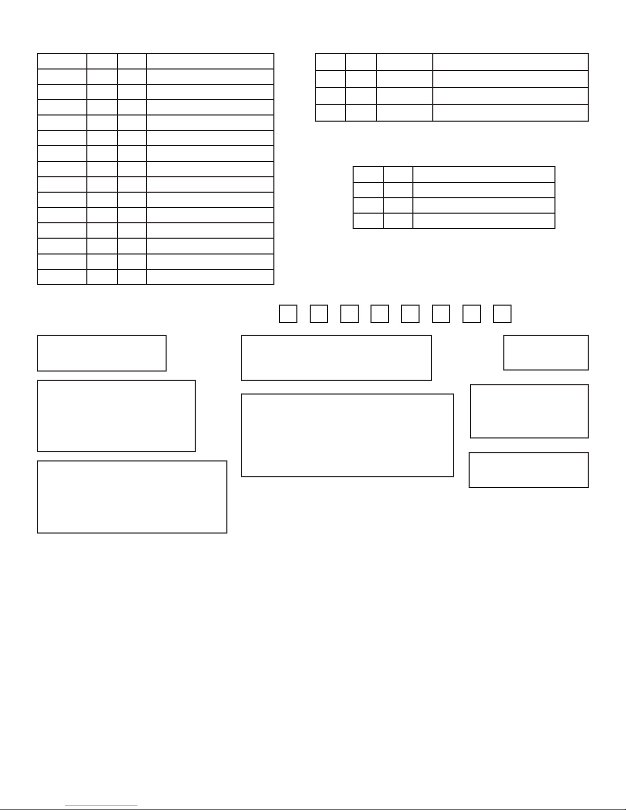
Location Short Open Function
J1 x T/C type J or K
“ x PT100 ohms DIN or JIS
J2 x Reverse control
“ x Direct control
J3 x 100°C span
J4 x 200°C span
J5 x 300°C span
J6 x 400°C span
J7 x 460°C span
J8 x 600°C span
J9 x 800°C span
J10 x 1200°C span
J11 x ON-OFF control
“ x Time proportional control
Function of Solder Gaps J12–J13Function of Solder Gaps J1–J11
J12 J13 Cycle time Function
Short Short 20 sec. Relay output
Open Short 1 sec. SSR drive
Open Open 0.02 sec. Linear current or voltage output
Function of Solder Gaps J14–J15
J14 J15 Function
Short Open Positive setting
Open Open Positive and negative setting
Open Short Negative setting
1 2 6
Ordering Code:
Power Input box 1
4 = 90-264 VAC 50/60 Hz
TEC-805-
Control Mode box 4
1 = On - Off (used for valves and solenoids)
2 = Proportional(common for electric heaters)
Signal Input box 2
1 = Thermocouple: Type J
2 = Thermocouple: Type K
3 = RTD: 100 ohm PT, DIN 0.00385
4 = RTD: 100 ohm PT, JIS 0.00392
9 = Other
Output 1 box 5
1 = Relay: 5A / 240 VAC
2 = Pulse dc for SSR drive: 20 VDC (20 mA max)
3 = 4-20 mA, linear (max load 500 ohms)
4 = 0-20 mA, linear (max load 500 ohms)
5 = 0-10 VDC, linear (min. impedance 500K ohms)
9 = Other
Range code box 3
X = 0 to 499°F C = 0 to 299°C
V = 0 to 999°F E = 0 to 499°C
W = 0 to 1999°F H = 0 to 999°C
Other ranges are available for large volume
orders. Consult Tempco for more information.
WARRANTY
Tempco Electric Heater Corporation is pleased to offer
suggestions on the use of its products. However, Tempco makes
no warranties or representations of any sort regarding the fitness
for use, or the application of its products by the Purchaser. The
selection, application, or use of Tempco products is the
Purchaser's responsibility. No claims will be allowed for any
damages or losses, whether direct, indirect, incidental, special, or
consequential. Specifications are subject to change without
notice. In addition, Tempco reserves the right to make changes–
without notification to the Purchaser–to materials or processing
that do not affect compliance with any applicable specification.
TEC Temperature Controllers are warranted to be free from
defects in material and workmanship for two (2) years after
delivery to the first purchaser for use. Tempco's sole
responsibility under this warranty, at Tempco's option, is limited
to replacement or repair, free of charge, or refund of purchase
price within the warranty period specified. This warranty does not
apply to damage resulting from transportation, alteration, misuse,
or abuse.
345 78
0
0
Output 2 box 6
0 = Not Available
Alarm box 7
0 = None
1 = Relay: 2A / 240 VAC
Deviation alarm
Communication box 8
0 = Not Available
RETURNS
No product returns can be accepted without a completed Return
Material Authorization (RMA) form.
TECHNICAL SUPPORT
Technical questions and troubleshooting help is available from
Tempco. When calling or writing please give as much
background information on the application or process as possible.
TEMPCO Electric Heater Corporation
607 N. Central Avenue
Wood Dale, IL 60191-1452 USA
E-mail: [email protected]
Phone: 630-350-2252 Toll Free: 800-323-6859
Web: Tempco.com
Page 4 of 4
 Loading...