

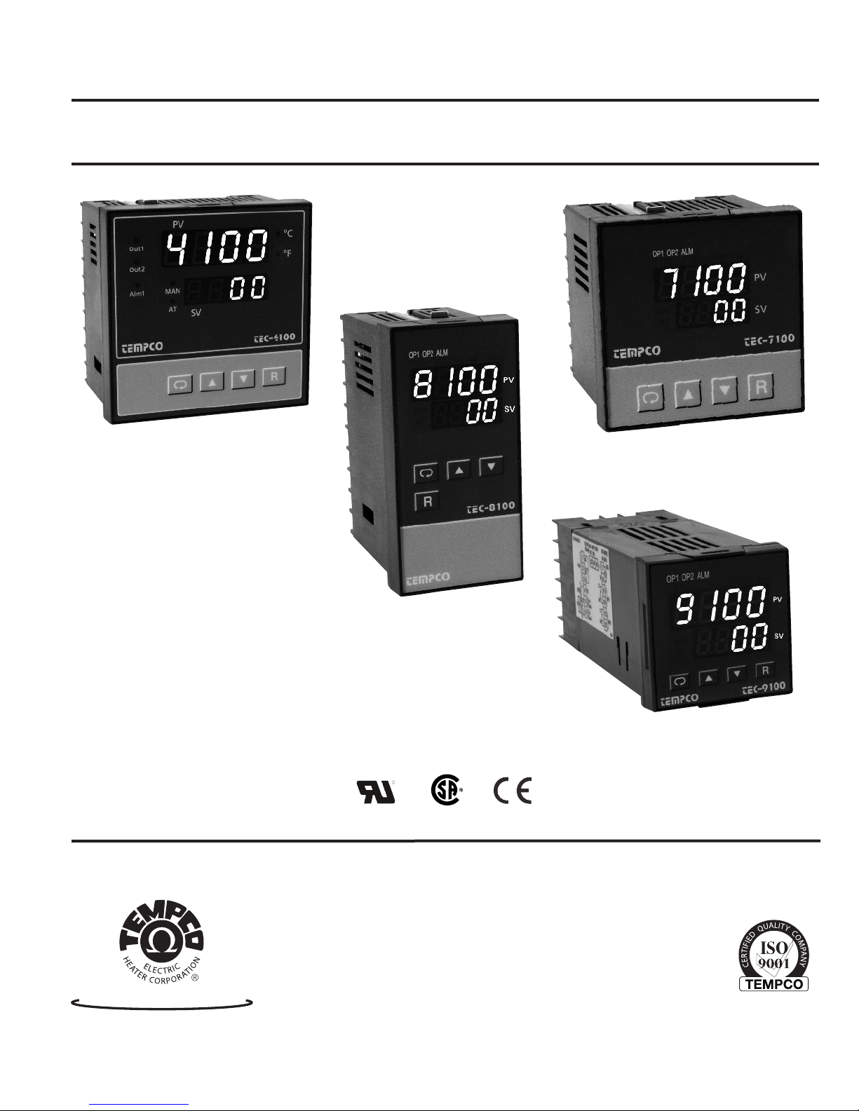
Tempco TEC-4100, TEC-7100, TEC-9100, TEC-8100 Instruction Manual
Instruction Manual
TEC-4100 / 7100 / 8100 / 9100
Auto-Tune Fuzzy / PID Process
Temperature Controller
Agency Approvals
TEMPCO Electric Heater Corporation
607 N. Central Avenue • Wood Dale, IL 60191-1452 USA
Tel: 630-350-2252 • Toll Free: 800-323-6859
Fax: 630-350-0232 • E-mail: info@tempco.com
Serving Industry Since 1972
Web: www.tempco.com
Manual TEC-100 Revision 9/2013

NOTES

Using the Manual
nstallers . . . . . . . . . . . . . . . . . . . . . . . . . . . Read Chapter 1, 2
I
System Designer . . . . . . . . . . . . . . . . . . . . . Read All Chapters
Expert User . . . . . . . . . . . . . . . . . . . . . . . . . Read Page 11
NOTE:
t is strongly recommended that a process should incorporate
I
a LIMIT CONTROL such as the TEC-910 which will shut
down the equipment at a preset process condition in order to
preclude possible damage to products or system.
Information in this user's manual is subject to change without
notice.
Copyright © 2012, Tempco Electric Heater Corporation, all
rights reserved. No part of this publication may be reproduced,
transmitted, transcribed or stored in a retrieval system, or translated into any language in any form by any means without the
written permission of Tempco Electric Heater Corporation.
CONTENTS
Page No
Chapter 1 Overview
1-1 General . . . . . . . . . . . . . . . . . . . . . . . . . . . . . . . . . . . . . 1
1-2 Ordering Code . . . . . . . . . . . . . . . . . . . . . . . . . . . . . . . 2
1-3 Programming Port . . . . . . . . . . . . . . . . . . . . . . . . . . . . 3
1-4 Keys and Displays . . . . . . . . . . . . . . . . . . . . . . . . . . . . 3
1-5 Menu Overview . . . . . . . . . . . . . . . . . . . . . . . . . . . . . . 4
1-6 Parameter Descriptions . . . . . . . . . . . . . . . . . . . . . . . . . 5
Chapter 2 Installation
2-1 Unpacking . . . . . . . . . . . . . . . . . . . . . . . . . . . . . . . . . . . 7
2-2 Mounting . . . . . . . . . . . . . . . . . . . . . . . . . . . . . . . . . . . 7
2-3 Wiring Precautions . . . . . . . . . . . . . . . . . . . . . . . . . . . . 8
2-4 Power Wiring . . . . . . . . . . . . . . . . . . . . . . . . . . . . . . . . 9
2-5 Sensor Installation Guidelines . . . . . . . . . . . . . . . . . . . 9
2-6 Sensor Input Wiring . . . . . . . . . . . . . . . . . . . . . . . . . . . 9
2-7 Control Output Wiring . . . . . . . . . . . . . . . . . . . . . . . . . 9
2-8 Alarm Wiring . . . . . . . . . . . . . . . . . . . . . . . . . . . . . . . . 11
2-9 Data Communication . . . . . . . . . . . . . . . . . . . . . . . . . . 11
Chapter 3 Programming
3-1 Lockout . . . . . . . . . . . . . . . . . . . . . . . . . . . . . . . . . . . . 12
3-2 Signal Input . . . . . . . . . . . . . . . . . . . . . . . . . . . . . . . . . 12
3-3 Control Outputs . . . . . . . . . . . . . . . . . . . . . . . . . . . . . . 12
3-4 Alarm . . . . . . . . . . . . . . . . . . . . . . . . . . . . . . . . . . . . . . 14
3-5 Configuring User Menu . . . . . . . . . . . . . . . . . . . . . . . 15
3-6 Ramp . . . . . . . . . . . . . . . . . . . . . . . . . . . . . . . . . . . . . . 15
3-7 Dwell Timer . . . . . . . . . . . . . . . . . . . . . . . . . . . . . . . . . 15
3-8 PV Shift . . . . . . . . . . . . . . . . . . . . . . . . . . . . . . . . . . . . 16
3-9 Digital Filter . . . . . . . . . . . . . . . . . . . . . . . . . . . . . . . . 16
3-10 Failure Transfer . . . . . . . . . . . . . . . . . . . . . . . . . . . . . 16
3-11 Auto-tuning . . . . . . . . . . . . . . . . . . . . . . . . . . . . . . . . 17
3-12 Manual Tuning . . . . . . . . . . . . . . . . . . . . . . . . . . . . . 17
3-13 Manual Control . . . . . . . . . . . . . . . . . . . . . . . . . . . . . 18
3-14 Data Communication . . . . . . . . . . . . . . . . . . . . . . . . . 18
3-15 Process Variable (PV) Retransmission. . . . . . . . . . . . 18
Chapter 4 Applications
4-1 Heat Only Control With Dwell Timer . . . . . . . . . . . . . 19
4-2 Cool Only Control . . . . . . . . . . . . . . . . . . . . . . . . . . . . 19
4-3 Heat-Cool Control . . . . . . . . . . . . . . . . . . . . . . . . . . . . 20
Chapter 5 Calibration . . . . . . . . . . . . . . . 21
Chapter 6 Specifications . . . . . . . . . . . 23
Chapter 7 Modbus Comm. . . . . . . . . . . 25
7-1 Functions Supported . . . . . . . . . . . . . . . . . . . . . . . . . . 25
7-2 Exception Responses . . . . . . . . . . . . . . . . . . . . . . . . . . 26
7-3 Parameter Table . . . . . . . . . . . . . . . . . . . . . . . . . . . . . . 26
7-4 Data Conversion . . . . . . . . . . . . . . . . . . . . . . . . . . . . . . 28
7-5 Communication Example . . . . . . . . . . . . . . . . . . . . . . . 29
Appendix
A-1 Error Codes . . . . . . . . . . . . . . . . . . . . . . . . . . . . . . . . . 30
A-2 Warranty . . . . . . . . . . . . . . . . . . . . . . . . . . . . . . . . . . . 31
FIGURES & TABLES
Page No
Figure 1.1 Fuzzy Control Advantage. . . . . . . . . . . . . . . . . . 1
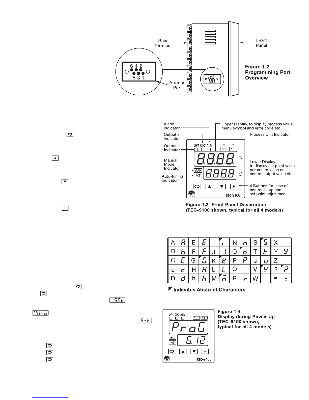
Figure 1.2 Programming Port Overview . . . . . . . . . . . . . . . 3
Figure 1.3 Front Panel Description . . . . . . . . . . . . . . . . . . 3
Figure 1.4 Display during Power UP . . . . . . . . . . . . . . . . . 3
Figure 2.1 Mounting Dimensions . . . . . . . . . . . . . . . . . . . . 7
Figure 2.2 Lead Termination for TEC-4100,
TEC-8100 and TEC-7100 . . . . . . . . . . . . . . . . . 8
Figure 2.3 Lead Termination for TEC-9100 . . . . . . . . . . . . 8
Figure 2.4 Rear Terminal Connection for
TEC-4100 and TEC-8100 . . . . . . . . . . . . . . . . . 8
Figure 2.5 Rear Terminal Connection for TEC-7100 . . . . . 8
Figure 2.6 Rear Terminal Connection for TEC-9100 . . . . . 8
Figure 2.7 Power Supply Connections . . . . . . . . . . . . . . . . 9
Figure 2.8 Sensor Input Wiring . . . . . . . . . . . . . . . . . . . . . 9
Figure 2.9 Output 1 Relay or Triac (SSR) to
Drive Load . . . . . . . . . . . . . . . . . . . . . . . . . . . . 9
Figure 2.10 Output 1 Relay or Triac (SSR) to
Drive Contactor . . . . . . . . . . . . . . . . . . . . . . . 10
Figure 2.11 Output 1 Pulsed Voltage to Drive SSR . . . . . 10
Figure 2.12 Output 1 Linear Current . . . . . . . . . . . . . . . . . 10
Figure 2.13 Output 1 Linear Voltage . . . . . . . . . . . . . . . . . 10
Figure 2.14 Output 2 Relay or Triac (SSR) to
Drive Load . . . . . . . . . . . . . . . . . . . . . . . . . . . 10
Figure 2.15 Output 2 Relay or Triac (SSR) to
Drive Contactor . . . . . . . . . . . . . . . . . . . . . . . . 10
Figure 2.16 Output 2 Pulsed Voltage to Drive SSR . . . . . . 10
Figure 2.17 Output 2 Linear Current . . . . . . . . . . . . . . . . . 10
Figure 2.18 Output 2 Linear Voltage . . . . . . . . . . . . . . . . . 10
Figure 2.19 Alarm Output to Drive Load . . . . . . . . . . . . . 11
Figure 2.20 Alarm Output to Drive Contactor . . . . . . . . . . 11
Figure 2.20.1 Dwell Timer Function . . . . . . . . . . . . . . . . . 11
Figure 2.21 RS-485 Wiring. . . . . . . . . . . . . . . . . . . . . . . . . 11
Figure 2.22 RS-232 Wiring. . . . . . . . . . . . . . . . . . . . . . . . . 11
Figure 2.23 Configuration of RS-232 Cable . . . . . . . . . . . 11
Figure 3.1 Conversion Curve for Linear Type
Process Value . . . . . . . . . . . . . . . . . . . . . . . . . . 12
Figure 3.2 Heat Only ON-OFF Control . . . . . . . . . . . . . . . 13
Figure 3.3 Output 2 Deviation High Alarm . . . . . . . . . . . . 14
Figure 3.4 Output 2 Process Low Alarm . . . . . . . . . . . . . . 14
Figure 3.5 RAMP Function . . . . . . . . . . . . . . . . . . . . . . . . 15
Figure 3.6 Dwell Timer Function . . . . . . . . . . . . . . . . . . . . 15
Figure 3.7 PV Shift Application . . . . . . . . . . . . . . . . . . . . . 16
Figure 3.8 Filter Characteristics . . . . . . . . . . . . . . . . . . . . . 16
Figure 3.9 Effects of PID Adjustment . . . . . . . . . . . . . . . . 17
Figure 4.1 Heating Control Example . . . . . . . . . . . . . . . . . 19
Figure 4.2 Cooling Control Example . . . . . . . . . . . . . . . . . 19
Figure 4.3 Heat-Cool Control Example . . . . . . . . . . . . . . . 20
Figure 5.1 RTD Calibration . . . . . . . . . . . . . . . . . . . . . . . . 21
Figure 5.2 Cold Junction Calibration Setup . . . . . . . . . . . . 22
Table 1.1 Display Form of Characters . . . . . . . . . . . . . . . . 3
Table 3.1 Heat-Cool Control Setup Value . . . . . . . . . . . . . 12
Table 3.2 PID Adjustment Guide . . . . . . . . . . . . . . . . . . . . 17
Table A.1 Error Codes and Corrective Actions . . . . . . . . . 30

NOTES
Chapter 1 Overview
1–1 General
Tempco’s TEC-x100 Series Fuzzy Logic plus PID microprocessor-based controllers incorporate two bright easy to read 4-digit
ED displays, indicating process value and set point value. The
L
process value (PV) display is always the top digital display. The
setpoint (SV) display is always the bottom display. Fuzzy Logic
technology enables a process to reach a predetermined set point
in the shortest time with a minimum of overshoot during powerup or external load disturbance.
TEC-9100 is a 1/16 DIN size panel mount controller. TEC-7100
is a 72×72 DIN size panel mount controller. TEC-8100 is a 1/8
DIN size panel mount controller and TEC-4100 is a 1/4 DIN size
panel mount controller. These units are powered by 11–26 or
90–250 VDC/VAC 50/60 Hz supply, incorporating a 2 amp control relay output as standard. The second output can be used as a
cooling control or an alarm. Both outputs can select triac, 5V
logic output, linear current, or linear voltage to drive an external
device. There are six types of alarm plus a dwell timer that can
be configured for the third output. The units are fully programmable for PT100 RTD and thermocouple types J, K, T, E, B, R,
S, N, and L with no need to modify the unit. The input signal is
digitized by using an 18-bit A to D converter. Its fast sampling
rate allows the unit to control fast processes.
Digital communications RS-485 or RS-232 (excluding TEC-
100) are available as an additional option. These options allow
7
the units to be integrated with supervisory control systems and
software.
A programming port is available for automatic configuration,
calibration, and testing without the need to access the keys on the
front panel.
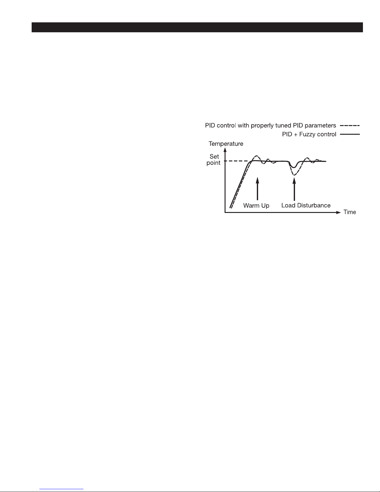
By using proprietary Fuzzy modified PID technology, the control loop will minimize overshoot and undershoot in a short time.
The following diagram is a comparison of results with and without Fuzzy technology.
High accuracy
This series is manufactured with custom
designed ASIC (Application Specific
Integrated Circuit) technology which
contains an 18-bit A to D converter for
high resolution measurement (true 0.1°F
resolution for thermocouple and PT100)
and a 15-bit D to A converter for linear
current or voltage control output. The
ASIC technology provides improved
operating performance, low cost,
enhanced reliability and higher density.
Fast sampling rate
The sampling rate of the input A to D
converter is 5 times/second. The fast
sampling rate allows this series to control
fast processes.
Fuzzy control
The function of Fuzzy control is to adjust
PID parameters from time to time in
order to make manipulation of the output
value more flexible and adaptive to various processes. The result is to enable a
process to reach a predetermined set point
in the shortest time, with the minimum of
overshoot and undershoot during powerup or external load disturbance.
Figure 1.1 Fuzzy Control Advantage
Digital communication
The units are equipped with an optional
RS-485 or RS-232 interface cards to provide digital communication. By using
twisted pair wires, up to 247 units can be
connected together via RS-485 interface
to a host computer.
Programming port
A programming port can be used to connect the unit to a PC for quick configuration. It also can be connected to an ATE
system for automatic testing and calibration.
Auto-tune
The auto-tune function allows the user to
simplify initial setup for a new system.
An advanced algorithm is used to obtain
an optimal set of control parameters for
the process, and it can be applied either as
the process is warming up (cold start) or
when the process is in a steady state
(warm start).
Lockout protection
Depending on security requirements, one
of four lockout levels can be selected to
prevent the unit from being changed
without permission.
Bumpless transfer
Bumpless transfer allows the controller to
continue to control if the sensor breaks by
using its previous value. Hence, the
process can be controlled temporarily as
if the sensor is normal.
Soft-start ramp
The ramping function is performed during power up as well as any time the set
point is changed. It can be ramping up or
ramping down. The process value will
reach the set point at a predetermined
constant rate.
Digital filter
A first order low pass filter with a programmable time constant is used to
improve the stability of the process value.
This is particularly useful in certain
applications where the process value is
too unstable to be read.
SEL function
The units have the flexibility to allow the
user to select those parameters which are
most significant to him and put these
parameters in the front of the display
sequence. Up to eight parameters can be
selected to allow the user to build his own
display sequence.
1

1–2 Ordering Code
TEC-4100TEC-7100TEC-8100-
Power Input
4 = 90-250 VAC
5 = 11-26 VAC/VDC
9 = Other
Signal Input
Universal, can be
programmed in the field
for item 5 or 6
= TC: *J,K,T,E,B,R,S,N,L
5
-60 mV
0
6 = RTD: *PT100 DIN,
PT100 JIS
7 = 0-1 VDC
8 = *0-5, 1-5 VDC
A = 0-10 VDC
B = *4-20, 0-20 mA
9 = Other
*indicates default value
Output 1
1 = Relay: 2A/240 VAC
2 = Pulse dc for SSR drive:
5 Vdc (30 mA max)
3 = Isolated, 4-20 mA (default)
0-20 mA
4 = Isolated, VDC, 1-5 (default)
0-5, 0-1
5 = Isolated, VDC, 0-10
6 = Triac-SSR output
1A/240 VAC
C = Pulse dc for SSR drive:
14 Vdc (40 mA max)
9 = Other
Output 2
0 = None
1 = Relay: 2A / 240 VAC
2 = Pulse dc for SSR drive: 5 Vdc (30 mA max)
3 = Isolated, 4-20 mA (default), 0-20 mA
4 = Isolated VDC, 1-5 (default), 0-5, 0-1
5 = Isolated VDC, 0-10
6 = Triac-SSR output 1A / 240 VAC
7 = Isolated 20V @ 25 mA DC, Output Power Supply
8 = Isolated 12V @ 40 mA DC, Output Power Supply
9 = Isolated 5V @ 80 mA DC, Output Power Supply
C = Pulse dc for SSR drive: 14 VDC (40 mA max)
A = Other
Alarm
0 = None
1 = Relay: 2A/240 VAC,
SPDT
9 = Other
Communication
0 = None
1 = RS-485 Interface
2 = RS-232 Interface
(not available for TEC-7100)
= Retransmission 4-20 mA
3
default), 0-20 mA
(
4 = Retransmission 1-5 Vdc
(default), 0-5 VDC
5 = Retransmission 0-10 VDC
9 = Other
NEMA 4X / IP65
0 = No
1 = Yes
EC-9100-
T
ower Input
P
4 = 90-250 VAC
5 = 11-26 VAC/VDC
9 = Other
Signal Input
Universal, can be programmed in the field
for item 5 or 6
= TC: *J,K,T,E,B,R,S,N,L 0-60mV
5
6 = RTD: *PT100 DIN, PT100 JIS
7 = 0-1 Vdc
8 = *0-5, 1-5 VDC
A = 0-10 VDC
B = *4-20, 0-20 mA
9 = Other
*indicates default value
Output 1
1 = Relay: 2A / 240 VAC
2 = Pulse dc for SSR drive: 5 VDC (30 mA max)
3 = Isolated, 4-20 mA (default), 0-20 mA
4 = Isolated, VDC, 1-5 (default), 0-5, 0-1
5 = Isolated, VDC, 0-10
6 = Triac-SSR output 1A/240 VAC
C = Pulse dc for SSR drive:14 VDC (40 mA max)
9 = Other
Output 2
0 = None
1 = Relay: 2A/240 VAC
2 = Pulse dc for SSR drive: 5 VDC (30 mA max)
3 = Isolated, 4-20 mA (default), 0-20 mA
4 = Isolated VDC, 1-5 (default), 0-5, 0-1
5 = Isolated VDC, 0-10
6 = Triac-SSR output 1A/240 Vac
7 = Isolated 20V @ 25 mA DC, Output Power Supply
8 = Isolated 12V @ 40 mA DC, Output Power Supply
9 = Isolated 5V @ 80 mA DC, Output Power Supply
C = Pulse dc for SSR drive: 14 VDC (40 mA max)
A = Other
Alarm
0 = None
1 = Relay: 2A / 240 VAC, SPDT
9 = Other
Communication
0 = None
1 = RS-485 Interface
2 = RS-232 Interface
3 = Retransmission 4-20 mA (default), 0-20 mA
4 = Retransmission 1-5 VDC (default), 0-5 VDC
5 = Retransmission 0-10 VDC
9 = Other
Case Options
0 = Panel mount standard
1 = Panel mount with NEMA 4X/IP65 front panel
2 = DIN rail mount
Data Communication Accessories:
TEC99001 Smart Network Adapter for third party SCADA software
which converts 255 channels of RS-485 or RS-422 to RS232 Network.
TEC99003 Smart Network Adapter for connecting the programming
port to the RS-232 PC serial port. Allows downloading and
reading of configuration information directly from a personal computer. Can be used with TEC-4100, TEC-7100, TEC8100 and TEC-9100.
2
TEC99030 "Tempco Config Set" PC software for use with TEC99003
Smart Network Adapter. (can be downloaded at no charge
from www.tempco.com)
Minimum System Requirements:
Microsoft Windows 2000, 98, 95, NT4.0
Pentium 200 MHz or faster
32 MB RAM (64 MB recommended)
Hard disk space: 2 MB
TEC99011 Programming port cable for TEC-4100, TEC-7100, TEC-
8100 and TEC-9100. Connects the controller to the
TEC99003 Smart Network Adapter.
R
1–3 Programming Port
The TEC99011 cable and TEC99003
network adapter can be used to con-
ect the programming port to a PC
n
for automatic configuration.
he programming port is used for
T
off-line automatic setup and testing
procedures only. Don't attempt to
make any connection to these pins
when the unit is used for a normal
control purpose.
1–4 Keys and Displays
KEYPAD OPERATION
SCROLL KEY:
This key is used to select a parameter to be viewed or adjusted.
UP KEY:
This key is used to increase the value of the selected parameter.
DOWN KEY:
This key is used to decrease the value of the selected parameter.
RESET KEY:
This key is used to:
1. Revert the display to show the process value.
2. Reset the latching alarm, once the alarm condition is removed.
3. Stop the manual control mode, auto-tuning mode, and calibration mode.
4. Clear the message of communication error and auto-tuning
error.
5. Restart the dwell timer when the dwell timer has timed out.
6. Enter the manual control menu when in failure mode.
ENTER KEY: Press for 5 seconds or longer.
Press for 5 seconds to:
1. Enter setup menu. The display shows .
2. Enter manual control mode—when manual control mode
is selected.
3. Enter auto-tuning mode—when auto-tuning mode is
selected.
4. Perform calibration to a selected parameter during the calibration procedure.
Press for 6.2 seconds to select manual control mode.
Press for 7.4 seconds to select auto-tuning mode.
Press for 8.6 seconds to select calibration mode.
Table 1.1 Display Form of Characters
Display program code of the product for
2.5 seconds.
The left diagram shows program number 6
for TEC-9100 with version 12.
The program no. for TEC-7100 is 13, for
TEC-8100 is 11 and for TEC-4100 is 12.
3
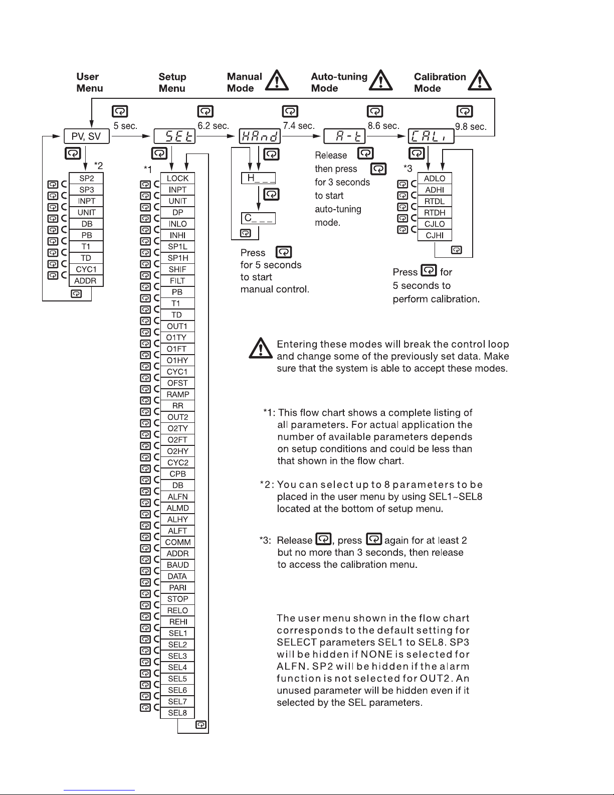
1–5 Menu Overview
4
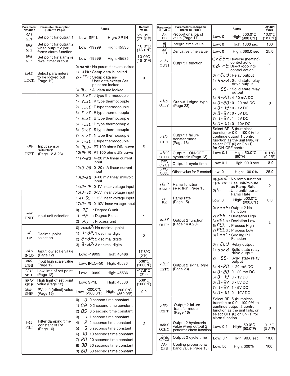
1–6 Parameter Descriptions
Continued…
5
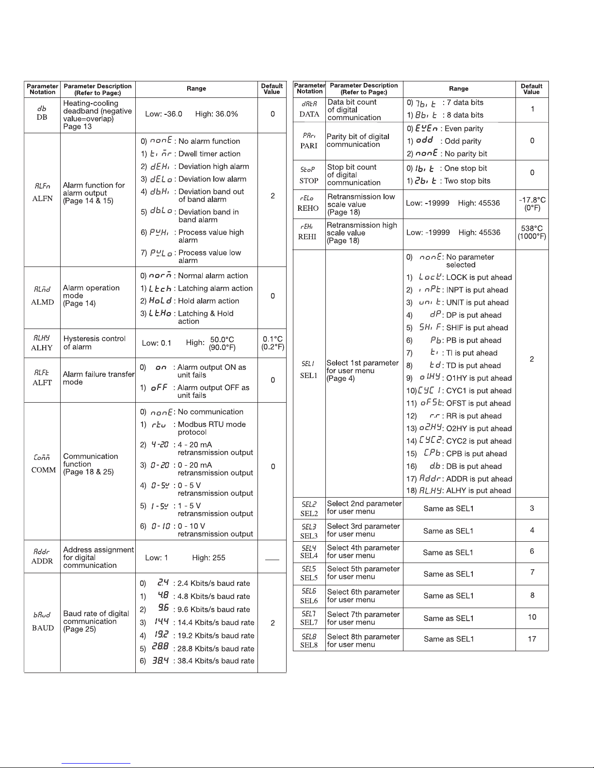
Parameter Descriptions,
Continued…
6
Chapter 2 Installation
Dangerous voltages capable of causing death are some-
times present in this instrument. Before installation or
beginning any troubleshooting procedures, the power to all
equipment must be switched off and isolated. Units suspected of
eing faulty must be disconnected and removed to a properly
b
equipped workshop for testing and repair. Component replacement and internal adjustments must be made by a qualified maintenance person only.
This instrument is protected throughout by double insula-
tion to minimize the possibility of fire or shock hazards,
do not expose this instrument to rain or excessive moisture.
Do not use this instrument in areas under hazardous con-
ditions such as excessive shock, vibration, dirt, moisture,
corrosive gases or oil. This control is not to be used in hazardous
locations as defined in Articles 500 and 505 of the National
Electrical Code. The ambient temperature of the area should not
exceed 122°F.
Remove stains from this instrument using a soft, dry
cloth. To avoid deformation or discoloration do not use
harsh chemicals, volatile solvent such as thinner, or strong detergents to clean this instrument.
2–1 Unpacking
Upon receipt of the shipment, remove the unit from the carton
and inspect the unit for shipping damage.
If there is any damage due to transit, report it and file a claim
with the carrier. Write down the model number, serial number,
and date code for future reference when corresponding with
Tempco. The serial number (S/N) and date code (D/C) are
labeled on the box and the housing of the control.
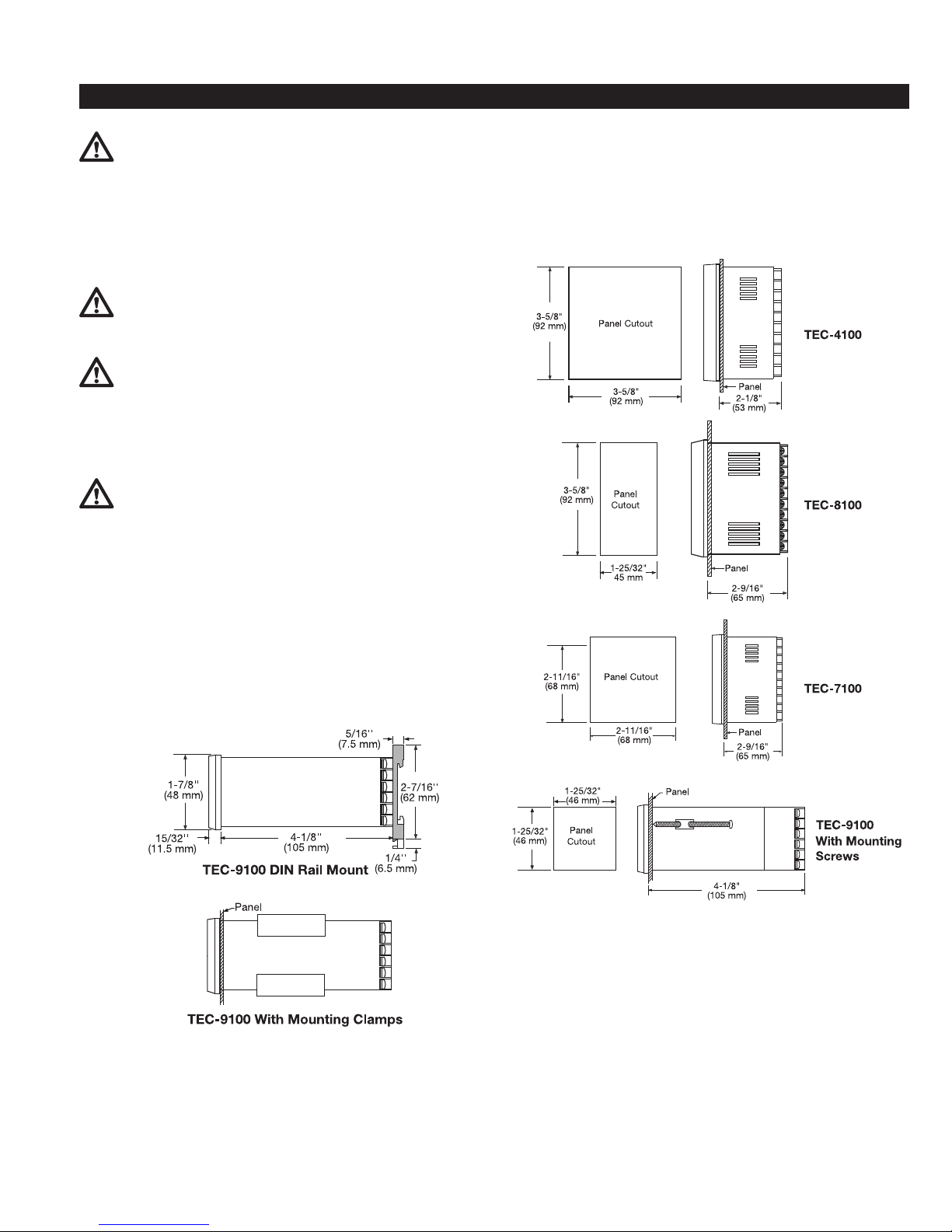
2–2 Mounting
emove mounting clamps or screws and insert the controller into
R
the panel cutout. Reinstall the mounting clamps or screws.
Gently tighten the screws or clamp until the front panel of the
controller fits snugly in the cutout.
Figure 2.1 Mounting Dimensions
NOTE:
The TEC-9100 Series may be supplied with either mounting
screws (2) or mounting clamps (2). The mounting clamps
are the newer type.
In clamp mounting, to remove the clamps before installation
lift under one of the edges and pull up (un-peel). To install
just snap back on and push the clamps towards the front of
the control until they are snug.
7
 Loading...