

Tempco TEC-2400, TEC-9400, TEC-8400, TEC-8450, TEC-4400 User Manual And Meeting Notes
...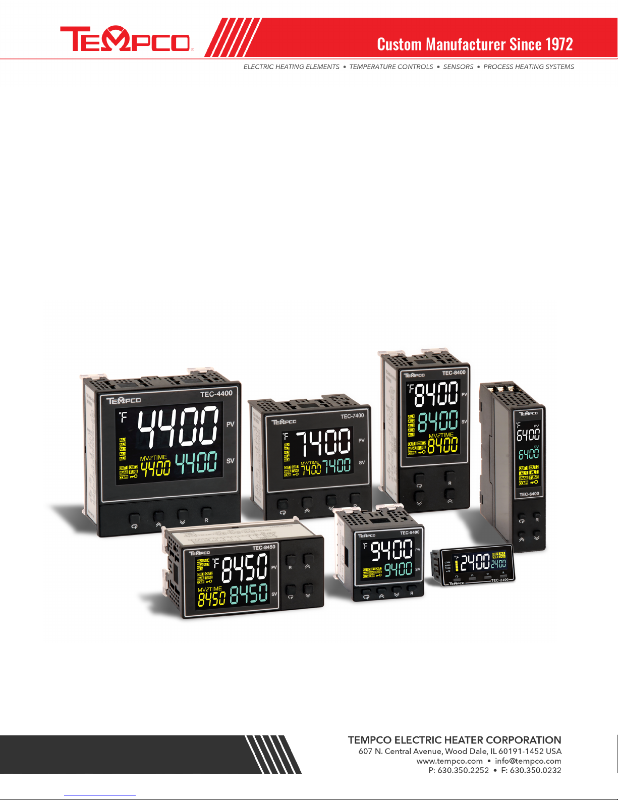
PID + Fuzzy Logic Process Controller
TEC-2400/9400/8400/8450/7400/4400/6400
User Manual and Meeting Notes
JT rev. 11/29/2018

Warning Symbol
This document contains notices that you should observe to ensure your own personal safety, as well as to
protect the product and connected equipment. These notices are highlighted in the manual by a warning triangle and
are marked as follows.
The danger symbol indicates that death or severe personal injury may result if proper precautions are not taken.
Do not proceed beyond a warning symbol until the indicated conditions are fully understood and met.
Preface
Original equipment manufacturer reserves the right to change information available in this document without
notice. Manufacturer is not liable for any damages incurred to equipment/personal during installation or use of
equipment as explained in this document. User must acquire sufficient knowledge & skills prior to using equipment in
the application and follow all the local standards & regulations to meet safety requirements.
Copyright
The documentation and the software included with this product are copyrighted 2018 by Tempco Electric
Heater Corp. All rights are reserved. Tempco Electric Heater Corp. reserves the right to make improvements in the
products described in this manual at any time without notice.
No part of this manual may be reproduced/copied/translated or transmitted in any form or by any means
without the prior written permission of Tempco Electric Heater Corp. The information we supply is believed to be
accurate and reliable as of this printing. However, we assume no responsibility for its use.
Warning!
Failure of devices such as the thermocouple/RTD sensor, heater output relay or temperature control may result in
severe damage to a product while in process, melting of the heater or a damaging fire. A latching over-temperature
protection device such as a Tempco model TEC-910 or TEC-410 high-limit controller with manual reset must be
installed in your process. This device should remove power to the heating circuit if the above failure occurs. We
recommend this device be classified as a safety control and carry FM, U.L/CSA Listing or certification. Failure to
install high-limit protection where a potential hazard exists could result in damage to equipment, property and possible
severe injury to personnel.
Page 2 of 44

TABLE OF CONTENTS
1! Introduction ------------------------------------------------------------------------------------------------------------------------------------------- 5!
1.1 Introduction ------------------------------------------------------------------------------------------------------------------------------------------- 5
1.2 Features ------------------------------------------------------------------------------------------------------------------------------------------------ 6
1.3 Specifications ----------------------------------------------------------------------------------------------------------------------------------------- 6
1.4 Keys and Displays ------------------------------------------------------------------------------------------------------------------------------------ 9
1.5 Menu Flowchart ------------------------------------------------------------------------------------------------------------------------------------ 10
1.5.1 User Menu ----------------------------------------------------------------------------------------------------------------------------------- 10
1.5.2 Setup Menu ---------------------------------------------------------------------------------------------------------------------------------- 11
1.5.2.1 Basic Menu (bASE) ----------------------------------------------------------------------------------------------------------------- 11
1.5.2.2 Output Menu (oUT) ---------------------------------------------------------------------------------------------------------------- 12
1.5.2.3 Event Input Menu (EI) ------------------------------------------------------------------------------------------------------------- 12
1.5.2.4 Alarm Menu (ALRM) --------------------------------------------------------------------------------------------------------------- 13
1.5.2.5 User Select Menu (SEL) ----------------------------------------------------------------------------------------------------------- 14
1.5.2.6 Communication Menu (CoMM) ------------------------------------------------------------------------------------------------ 14
1.5.2.7 Current Transformer Input Menu (Ct) ---------------------------------------------------------------------------------------- 15
1.5.2.8 Profile Menu (PRoF) --------------------------------------------------------------------------------------------------------------- 16
1.5.3 Manual Mode Menu ---------------------------------------------------------------------------------------------------------------------- 17
1.5.4 Auto-Tuning Mode ------------------------------------------------------------------------------------------------------------------------- 17
1.5.5 Calibration Mode --------------------------------------------------------------------------------------------------------------------------- 17
2! Installation and Wiring --------------------------------------------------------------------------------------------------------------------------- 18!
2.1 Unpacking -------------------------------------------------------------------------------------------------------------------------------------------- 18
2.2 Mounting --------------------------------------------------------------------------------------------------------------------------------------------- 19
2.3 Wiring ------------------------------------------------------------------------------------------------------------------------------------------------- 19
2.3.1 TEC-2400 Terminal Connection --------------------------------------------------------------------------------------------------------- 19
2.3.2 TEC-9400 Terminal Connection --------------------------------------------------------------------------------------------------------- 20
2.3.3 TEC-8400 & TEC-4400 Terminal Connection ---------------------------------------------------------------------------------------- 20
2.3.4 TEC-8450 Terminal Connection --------------------------------------------------------------------------------------------------------- 21
2.3.5 TEC-7400 Terminal Connection --------------------------------------------------------------------------------------------------------- 21
2.3.6 TEC-6400 Terminal Connection --------------------------------------------------------------------------------------------------------- 22
2.4 Wiring Example: Contactor --------------------------------------------------------------------------------------------------------------------- 22
2.5 Wiring Example: Solid State Relay ------------------------------------------------------------------------------------------------------------ 23
3! Programming ---------------------------------------------------------------------------------------------------------------------------------------- 23!
3.1 User Security ---------------------------------------------------------------------------------------------------------------------------------------- 23
3.2 Signal Input ------------------------------------------------------------------------------------------------------------------------------------------ 23
3.3 Control Output -------------------------------------------------------------------------------------------------------------------------------------- 24
3.3.1 Heat Only ON-OFF Control --------------------------------------------------------------------------------------------------------------- 24
3.3.2 Heat only P or PD Control ---------------------------------------------------------------------------------------------------------------- 25
3.3.3 Heat only PID Control --------------------------------------------------------------------------------------------------------------------- 25
3.3.4 Cool only Control --------------------------------------------------------------------------------------------------------------------------- 25
3.3.5 Other Setup Required --------------------------------------------------------------------------------------------------------------------- 26
3.3.6 CPB Programming -------------------------------------------------------------------------------------------------------------------------- 26
3.3.7 DB Programming --------------------------------------------------------------------------------------------------------------------------- 26
3.3.8 Output 2 ON-OFF Control (Alarm function) ----------------------------------------------------------------------------------------- 26
Page 3 of 44

3.4 Soft-Start --------------------------------------------------------------------------------------------------------------------------------------------- 27
3.5 Alarm -------------------------------------------------------------------------------------------------------------------------------------------------- 28
3.5.1 Alarm Types --------------------------------------------------------------------------------------------------------------------------------- 28
3.5.2 Alarm Modes -------------------------------------------------------------------------------------------------------------------------------- 29
3.5.2.1 Normal Alarm: ALMD = NORM ------------------------------------------------------------------------------------------------- 29
3.5.2.2 Latching Alarm: ALMD = LTCH -------------------------------------------------------------------------------------------------- 29
3.5.2.3 Holding Alarm: ALMD = HOLD -------------------------------------------------------------------------------------------------- 29
3.5.2.4 Latching / Holding Alarm: ALMD = LT.HO ------------------------------------------------------------------------------------ 30
3.5.2.5 Set Point Holding Alarm: ALMD = SP.HO ------------------------------------------------------------------------------------- 30
3.5.3 Alarm Delay ---------------------------------------------------------------------------------------------------------------------------------- 30
3.5.4 Alarm Failure Transfer -------------------------------------------------------------------------------------------------------------------- 30
3.6 User Select Menu Configuration --------------------------------------------------------------------------------------------------------------- 30
3.7 Ramp -------------------------------------------------------------------------------------------------------------------------------------------------- 31
3.7.1 Example without Dwell Timer ---------------------------------------------------------------------------------------------------------- 31
3.8 Dwell Timer ------------------------------------------------------------------------------------------------------------------------------------------ 31
3.9 User Calibration ------------------------------------------------------------------------------------------------------------------------------------ 32
3.10 Digital Filter -------------------------------------------------------------------------------------------------------------------------------------- 32
3.11 Failure Transfer --------------------------------------------------------------------------------------------------------------------------------- 33
3.11.1 Output 1 Failure Transfer ------------------------------------------------------------------------------------------------------------ 33
3.11.2 Output 2 Failure Transfer ------------------------------------------------------------------------------------------------------------ 33
3.11.3 Alarm Failure Transfer ---------------------------------------------------------------------------------------------------------------- 33
3.12 Auto-Tuning ------------------------------------------------------------------------------------------------------------------------------------- 33
3.12.1 Auto-Tuning Operation Steps ------------------------------------------------------------------------------------------------------- 34
3.12.2 Auto-Tuning Error ---------------------------------------------------------------------------------------------------------------------- 34
3.12.3 Solutions for an Auto Tuning Error ------------------------------------------------------------------------------------------------ 34
3.13 Manual Tuning ---------------------------------------------------------------------------------------------------------------------------------- 35
3.14 Manual Control --------------------------------------------------------------------------------------------------------------------------------- 36
3.14.1 Exiting Manual Control --------------------------------------------------------------------------------------------------------------- 36
3.15 Data Communication -------------------------------------------------------------------------------------------------------------------------- 36
3.15.1 RS-485 Setup ---------------------------------------------------------------------------------------------------------------------------- 36
3.16 Retransmission --------------------------------------------------------------------------------------------------------------------------------- 37
3.17 Heater Current Monitoring ------------------------------------------------------------------------------------------------------------------ 37
3.18 Event Input --------------------------------------------------------------------------------------------------------------------------------------- 38
3.18.1 Event Input Functions ----------------------------------------------------------------------------------------------------------------- 38
3.19 Remote Set Point ------------------------------------------------------------------------------------------------------------------------------- 39
3.20 Ramp and Soak Program --------------------------------------------------------------------------------------------------------------------- 39
3.20.1 PROF --------------------------------------------------------------------------------------------------------------------------------------- 39
3.20.2 RUN ---------------------------------------------------------------------------------------------------------------------------------------- 40
3.20.2.1 StAR ------------------------------------------------------------------------------------------------------------------------------------ 40
3.20.2.2 CoNt ------------------------------------------------------------------------------------------------------------------------------------ 40
3.20.2.3 PV --------------------------------------------------------------------------------------------------------------------------------------- 40
3.20.2.4 Hold ------------------------------------------------------------------------------------------------------------------------------------ 40
3.20.2.5 StoP ------------------------------------------------------------------------------------------------------------------------------------ 40
3.20.3 RMPU -------------------------------------------------------------------------------------------------------------------------------------- 40
3.20.4 STAR --------------------------------------------------------------------------------------------------------------------------------------- 40
3.20.5 END ----------------------------------------------------------------------------------------------------------------------------------------- 40
Page 4 of 44

3.20.5.1 SP1 -------------------------------------------------------------------------------------------------------------------------------------- 40
Model No
Mounting Type
DIN Size
Dimensions
LxWxD” (mm)
Depth Behind
Panel in(mm)
TEC-2400
Panel Mount
1/32 DIN
1 x 1 7/8 x 3 3/8”
(24x48x85)
3” (76)
TEC-9400
Panel Mount
1/16DIN
1 7/8 x 1 7/8 x 2 5/16”
(48x48x59)
2” (50)
TEC-8400/TEC-8450
Panel Mount
1/8 DIN
1 7/8 x 3 3/4 x 2 5/16”
(48x96x59)
2” (50)
TEC-7400
Panel Mount
3/16 DIN
2 27/32 x 2 27/32 x 2 5/16”
(72x72x59)
2” (50)
TEC-4400
Panel Mount
1/4 DIN
3 3/4 x 3 3/4 x 2 5/16
(96x96x59)
2” (50)
TEC-6400
DIN RAIL
7/8 x 3 3/4 x 3 5/32”
(22.5x96x80)
3.20.6 PFR ----------------------------------------------------------------------------------------------------------------------------------------- 40
3.20.6.1 CONT ----------------------------------------------------------------------------------------------------------------------------------- 41
3.20.6.2 PV --------------------------------------------------------------------------------------------------------------------------------------- 41
3.20.6.3 SP1 -------------------------------------------------------------------------------------------------------------------------------------- 41
3.20.6.4 OFF ------------------------------------------------------------------------------------------------------------------------------------- 41
3.20.7 Holdback ---------------------------------------------------------------------------------------------------------------------------------- 41
3.20.8 CYC ----------------------------------------------------------------------------------------------------------------------------------------- 42
3.20.9 Running, Holding and Stopping a Profile ---------------------------------------------------------------------------------------- 42
3.20.10 Viewing and Modifying the Profile Progress ------------------------------------------------------------------------------------ 42
3.20.11 Configuring the Profile ---------------------------------------------------------------------------------------------------------------- 42
3.20.11.1 Profile Segment Parameters ------------------------------------------------------------------------------------------------- 42
3.20.11.1.1 Target Set point -------------------------------------------------------------------------------------------------------------- 42
3.20.11.1.2 Ramp Time -------------------------------------------------------------------------------------------------------------------- 42
3.20.11.1.3 Soak Time ---------------------------------------------------------------------------------------------------------------------- 42
4! Factory Default Settings -------------------------------------------------------------------------------------------------------------------------- 43
1 Introduction
1.1 Introduction
The new generation of Tempco PID microprocessor-based Fuzzy logic controller series
incorporates two bright and easy to read LCD Displays which indicate Process Value (PV) and Set point (SP).
The Fuzzy Logic technology incorporated on these series controllers enables a process to reach a
predetermined set point in the shortest time with minimum of overshoot during start up (Power ON) or
external load disturbances (example: an oven door being opened).
Different controller models in this series are as follows:
These controllers are powered by an 11-26 or 90-250 VDC/VAC supply, incorporating a 2 Amp control relay output as
a standard. The second output can be used as a cooling control or an alarm. Both outputs can be selected as a 5VDC
or 14VDC logic output, linear current or linear voltage to drive an external device. There are six types of alarms and a
dwell timer that can be configured for the third output. The controllers are fully programmable for Linear current,
Linear Voltage, PT100 and thermocouple types J, K, T, E, B, R, S, N, L, U, P, C, and D. The input signal is
digitized by using an 18-bit A to D converter. Its fast sampling rate allows the controller to control fast processes.
Page 5 of 44

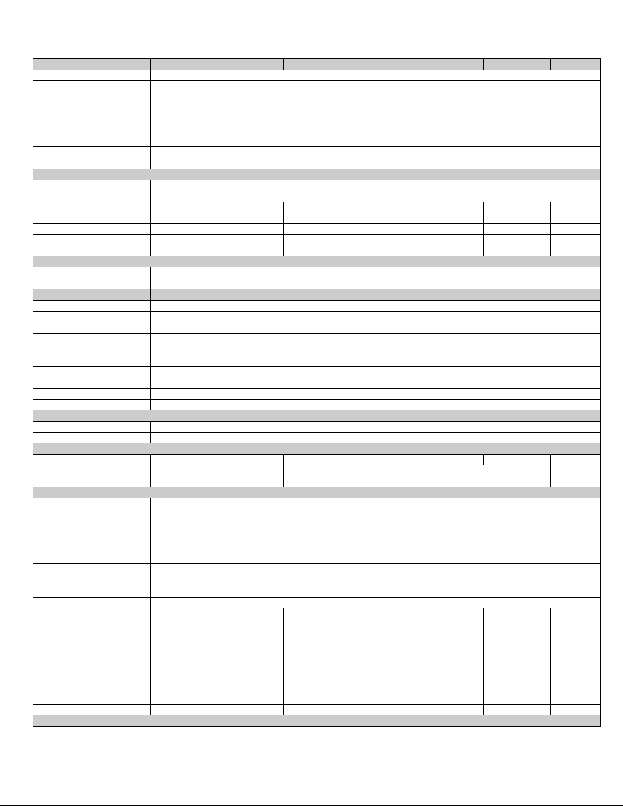
1.2 Features
Specification
TEC-2400
TEC-9400
TEC-8400
TEC-8450
TEC-7400
TEC-4400
TEC-6400
Power Supply
90 to 250VAC, 47 to63Hz , 20 to 28 VAC,47-63Hz / 11 to 40 VDC
Power Consumption
TEC-2400/TEC-6400: 8VA, 4W Maximum., TEC-9400: 10VA, 5W Maximum., TEC-7400/TEC-8400/TEC-8450/TEC-4400: 12VA,6W
Maximum
Signal Input
Type
Thermocouple(J,K,T,E,B,R,S,N,L,U,P,C,D), RTD(PT100(DIN), PT100(JIS)), Current(mA),Voltage(Volts)
Resolution
18 Bits
Sampling Rate
5 Times / Second (200msec)
Maximum Rating
-2VDC minimum, 12VDC maximum
Input Characteristics
Type
Range
Accuracy @ 25°C
Input Impedance
J
-120°C to 1000°C( -184°F to 1832°F)
±2°C
2.2 MΩ
K
-200°C to 1370°C (-328°F to 2498°F)
±2°C
2.2 MΩ
T
-250°C to 400°C ( -418°F to 752°F )
±2°C
2.2 MΩ
E
-100°C to 900°C( -148°F to 1652°F )
±2°C
2.2 MΩ
B
0°C to 1820°C( 32°F to 3308°F )
±2°C( 200°C to 1800°C )
2.2 MΩ
R
0°C to 1767.8°C( 32°F to 3214°F )
±2°C
2.2 MΩ
S
0°C to 1767.8°C( 32°F to 3214°F )
±2°C
2.2 MΩ
N
-250°C to 1300°C( -418°F to 2372°F)
±2°C
2.2 MΩ
L
-200°C to 900°C( -328°F to 1652°F )
±2°C
2.2 MΩ
U
-200°C to 600°C (-328°F to 1112°F)
±2°C
2.2 MΩ
P
0°C to 1395°C( 32°F to 2543°F )
±2°C
2.2 MΩ
C
0°C to 2300°C( 32°F to 4172°F )
±2°C
2.2 MΩ
D
0°C to 2300°C( 32°F to 4172°F )
±2°C
2.2 MΩ
PT100(DIN)
-200°C to 850°C( -328°F to 1562°F )
±0.4°C
1.3KΩ
PT100(JIS)
-200°C to 600°C( -328°F to 1112°F )
±0.4°C
1.3KΩ
mA
-3mA to 27mA
±0.05%
2.5Ω
VDC
-1.3VDC to 11.5VDC
±0.05%
1.5MΩ
Temperature Effect
1.5µV /°C for all inputs except mA input, 3.0µV /°C for mA
Sensor Lead Resistance Effect
Thermocouple: 0.2 µV /°Ω; 3-wire RTD: 2.6°C /Ω of Difference of Resistance of two leads
2-wire RTD: 2.6°C /Ω of Sum of Resistance of two leads
Burn-out Current
200nA
Common Mode Rejection
Ratio(CMRR)
120 dB
Normal Mode Rejection Ratio
(NMRR)
55dB
The new generation of low cost PID controllers have many features, some of which are listed below.
v High Accuracy 18 Bit A-D Conversion and 15 Bit D-A Conversion
v Fastest Sampling Rate 200msec
v Universal Input
v Fuzzy Logic + PID Technology
v Possibility of both RS-485 and analog retransmission
v 16 Segments of Ramp & Soak
v Current Transformer (CT) Inputs for heater break detection
v Up to 6 Event Inputs
v Remote Set point
v Auto-Tuning
v Bumpless Transfer
v Lockout Protection
v Bidirectional Menu Navigation
v Soft Start function
1.3 Specifications
Page 6 of 44

Page 7 of 44
Specification
TEC-2400
TEC-9400
TEC-8400
TEC-8450
TEC-7400
TEC-4400
TEC-6400
Sensor Break Detection
Sensor open for Thermocouple, RTD and mV inputs, Sensor short for RTD input ,
Below 1mA for 4-20mA input, Below 0.25VDC for 1 - 5VDC input, Not available for other inputs.
Sensor Break Response Time
Within 4 seconds for Thermocouple, RTD and mV inputs, 0.1 second for 4-20mA and 1 - 5VDC inputs.
Remote Set Point Input
Type
Linear Current, Linear Voltage
Range
-3mA to 27mA, -1.3VDC to 11.5VDC
Accuracy
±0.05 %
Remote Set Point
Not Available
Not Available
Available
Available
Available
Available
Not
Available
Input Impedance
Current: 2.5Ω, Voltage:1.5MΩ
Resolution
18 Bits
Sampling Rate
1.66 Times/Second
Maximum Rating
280mA maximum for Current Input, 12VDC Maximum for Voltage Input
Temperature Effect
±1.5µV/°C for Voltage Input , ±3.0µV/°C for Current Input
Sensor Break Detection
Below 1mA for 4-20mA input, Below 0.25VDC for 1 - 5VDC input, Not available for other inputs.
Sensor Break Responding
Time
0.1 Second
Event Input
Number of Event Inputs
1 2 6 6 2 6 1
Logic Low
-10VDC minimum, 0.8VDC maximum.
Logic High
2VDC minimum, 10VDC maximum
Functions
See availability table
CT Input
CT Type
CT98-1
Accuracy
±2%of Full scale Reading,±0.2A
Input Impedance
294Ω
Measurement Range
0 to 50AAC
Output of CT
0 to 5VDC
CT Mounting
Wall (Screw) Mount
Sampling Rate
1 Time/Second
Output 1 /Output 2
Type
Relay, Pulsed Voltage, Linear Voltage, or Linear Current
Relay Rating
2A, 240V AC,200000 Life Cycles for Resistive Load
Pulsed Voltage
Source Voltage 5VDC,Current Limiting Resistance 66Ω
Linear Output Resolution
15 Bits
Linear Output Regulation
0.02% for full load change
Linear Output Settling Time
0.1 Sec (Stable to 99.9%)
Isolation Breakdown Voltage
1000 VAC
Temperature Effect
±0.01% of Span/ °C
Load Capacity of Linear Output
Linear Current: 500Ω max., Linear Voltage: 10KΩ min
Alarm
Relay Type
Form A
Maximum Rating
2A,240VAC,200000 Life Cycles for Resistive Load
Alarm Functions
Dwell Timer, Deviation Low, Deviation High, Deviation Band Low, Deviation Band High, Process High, Process Low
Alarm Mode
Latching, Hold, Normal, Latching/Hold
Dwell Timer
0.1 to 4553.6 Minutes
Data Communication
Interface
RS-485
Protocol
Modbus RTU (Slave Mode)
Address
1 to 247
Baud Rate
2.8KBPS to 115.2KBPS
Parity Bit
None, Even or Odd
Stop Bit
1 or 2 Bits
Data Length
7 or 8 Bits
Communication Buffer
160 Bytes
Analog Retransmission
Output Signal
4-20mA, 0-20 mA,0 - 10VDC
Resolution
15 Bits
Accuracy
±0.05% of Span ± 0.0025% / °C
Page 8 of 44
Specification
TEC-2400
TEC-9400
TEC-8400
TEC-8450
TEC-7400
TEC-4400
TEC-6400
Load Resistance
0 to 500Ω for current output , 10KΩ minimum for Voltage Output
Output Regulation
0.01% for full load change
Output Setting Time
0.1Second (stable to 99.9%)
Isolation Breakdown
1000VAC min
Integral Linearity Error
±0.005% of span
Temperature Effect
±0.0025% of span /°C
Saturation Low
0mA or 0VDC
Saturation High
22.2mA or 5.55V,11.1V min
Linear Output Ranges
0 - 22.2mA (0 - 20mA/4 - 20mA), 0 - 5.55VDC (0 - 5VDC, 1 - 5VDC),0 - 11.1VDC (0 - 10VDC)
User Interface
Keypad
4 Keys
Display Type
4 Digit LCD Display
Number of Displays (setpoint,
temperature, ect.)
2 2 3 3 3 3 2
Upper Display Size
0.4”(10mm)
0.58”(15mm)
0.7”(17.7mm)
0.7”(17.7mm)
0.58”(15mm)
0.98”(25mm)
0.31”(8mm)
Lower Display Size
0.19”(4.8mm)
0.3”(7.8mm)
0.4”(11.2mm)
0.4”(11.2mm)
0.32”(8.3mm)
0.55”(14mm)
0.25”(6.5m
m)
Programming Port
Interface
Micro USB
PC Communication Function
Automatic Setup, Calibration and Firmware upgrade
Control Mode
Output 1
Reverse (Heating) or Direct (Cooling) Action
Output 2
PID cooling control, Cooling P band 50~300% of PB, Dead band -36.0 ~ 36.0 % of PB
ON-OFF
0.1~50.0°C (0.1~90.0°F ) hysteresis control ( P band = 0)
P or PD
0 - 100.0 % offset adjustment
PID
Fuzzy logic modified Proportional band 0.1 ~ 500.0°C(0.1~900.0°F), Integral time 0 – 3600 Secs, Derivative Time 0 - 360.0 Secs
Cycle Time
0.1 to 90.0 Seconds
Manual Control
Heat(MV1) and Cool(MV2)
Auto-Tuning
Cold Start and Warm Start
Failure Mode
Auto transfer to manual mode while sensor break or A-D Converter damage
Ramping Control
0 to 500.0°C (0 to 900.0°F)/Minute or 0 to 500.0°C (0 to 900.0°F)/Hour Ramp Rate
Digital Filter
Function
First Order
Time Constant
0,0.2, 0.5, 1, 2, 5, 10, 20, 30, 60 Seconds, Programmable
Profiler
Availability
No
No
Option
Option
Option
Option
No
Number of Programs
NA
NA
1 Program with 16 Segments, 2 Programs with 8 Segments each, or 4
Programs with 4 Segments each
NA
Environmental and Physical Specifications
Operating Temperature
-10°C to 50°C
Storage Temperature
-40°C to 60°C
Humidity
0 to 90 % RH (Non-Condensing)
Altitude
2000 Meters Maximum
Pollution
Degree II
Insulation Resistance
20MΩ Minimum(@500V DC)
Dielectric Strength
2000VAC,50/60 Hz for 1 Minute
Vibration Resistance
10 to 55 Hz , 10m/s2 for 2 Hours
Shock Resistance
200 m/s2(20g)
Housing
Flame Retardant Polycarbonate
Mounting
Panel
Panel
Panel
Panel
Panel
Panel
DIN Rail
Dimensions H*W*D:” (mm)
15/16 x 1 7/8 x 3
13/16”
(24*48*92)
1 7/8 x 1 7/8 x
2 3/8”
(48*48*59)
3 3/4 x 1 7/8 x
2 3/8”
(96*48*59)
1 7/8 x 3 3/4 x
2 3/8”
(48*96*59)
2 27/32 x 2
27/32 x 2 3/8”
(72*72*59)
3 3/4 x 3 3/4 x
2 3/8”
(96*96*59)
3 3/4 x 7/8
x
3 11/16”
(96*22.5*8
3)
Depth Behind Panel” (mm)
3” (84)
2” (50)
2” (50)
2” (50)
2” (50)
2” (50)
Cut Out Dimensions” (mm)
7/8 x 1 25/32”
(22*45)
1 25/32 x 1
25/32” (45*45)
1 25/32 x 3 5/8”
(45*92)
3 5/8 x 1 25/32”
(92*45)
2 11/16 x 2
11/16” (68*68)
3 5/8 x 3 5/8”
(92*92)
Weight Lbs. (grams)
.26 (120)
.35 (160)
.48 (220)
.48 (220)
.41 (190)
.64 (290)
.35 (160)
Approval Standards
Specification
TEC-2400
TEC-9400
TEC-8400
TEC-8450
TEC-7400
TEC-4400
TEC-6400
Safety
UL61010-1, CSA 22.2 No.61010-1-12, EN61010-1 ( IEC1010-1 )
Protective Class
IP66 for Panel (In process), IP20 for terminals and housing. All indoor use.
EMC
EN61326
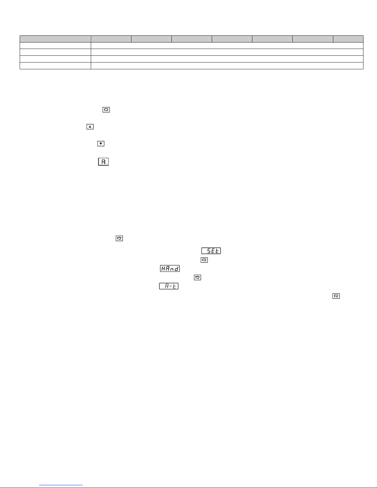
1.4 Keys and Displays
KEYPAD OPERATION
SCROLL KEY:
This key is used to scroll through a menu to select a parameter to be viewed or adjusted.
UP KEY:
This key is used to increase the value of the selected parameter.
DOWN KEY:
This key is used to decrease the value of the selected parameter.
RESET KEY:
This key is used to:
1. Revert the display to the home screen.
2. Reset a latching alarm once the alarm condition is removed.
3. Stop manual control mode, Auto-Tuning mode or calibration mode.
4. Clear an Auto-Tuning or communication error message.
5. Restart the dwell timer when the dwell timer has timed out.
6. Enter the manual control menu if failure mode occurs.
ENTER KEY: Press and hold for 5 seconds or longer to:
1. Enter the setup menu. The display will show .
2. Enter manual control mode. Press and hold for 6.2 seconds, then let go, to select manual control
mode. The display will show .
3. Enter Auto-Tuning mode. Press and hold for 7.4 seconds, then let go to select Auto-Tuning
mode. The display will show .
4. Perform calibration of a selected parameter during the calibration procedure. Press and hold for
8.6 seconds, then let go to select calibration mode.
During power-up, the upper display will show PROG and the lower display will show the
Firmware version for 6 seconds.
Page 9 of 44
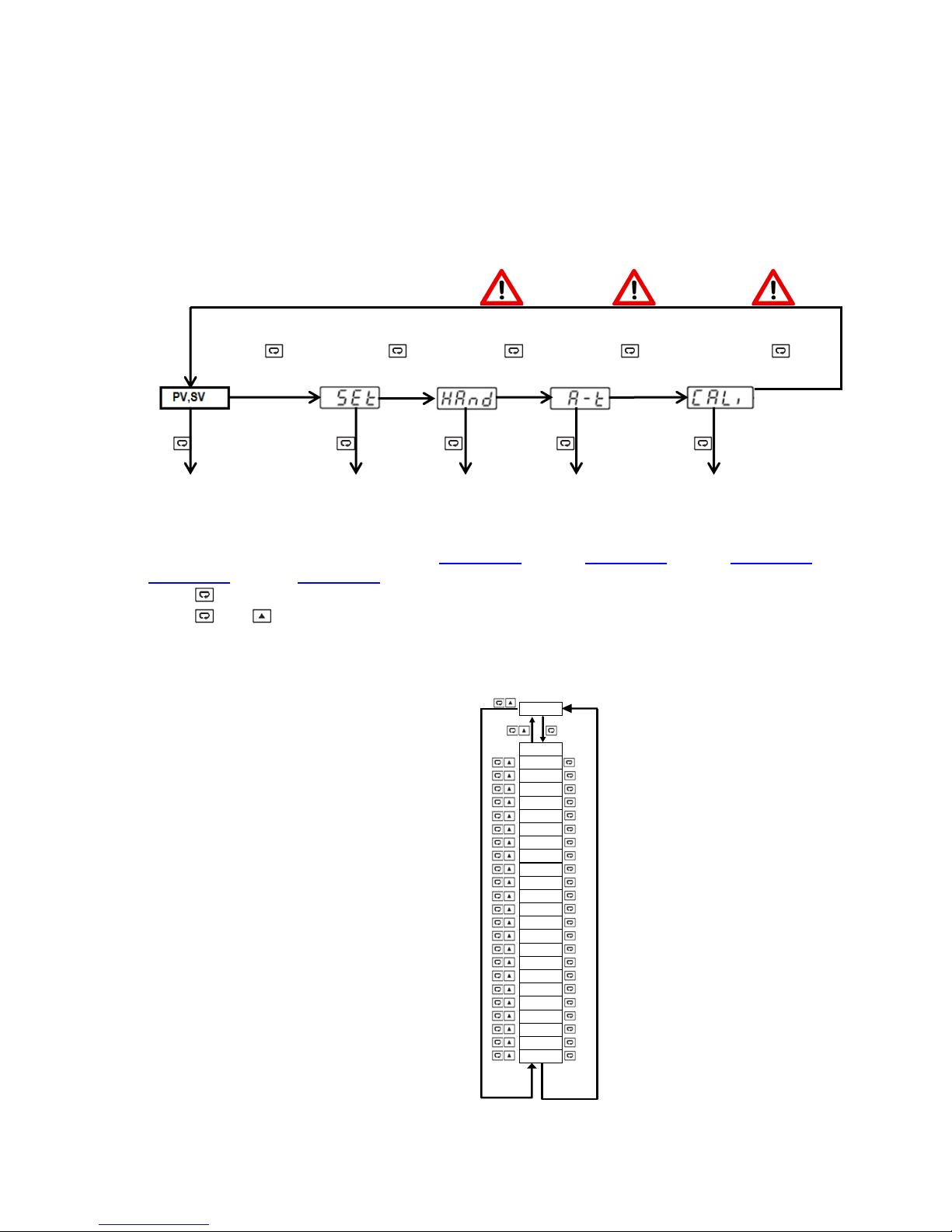
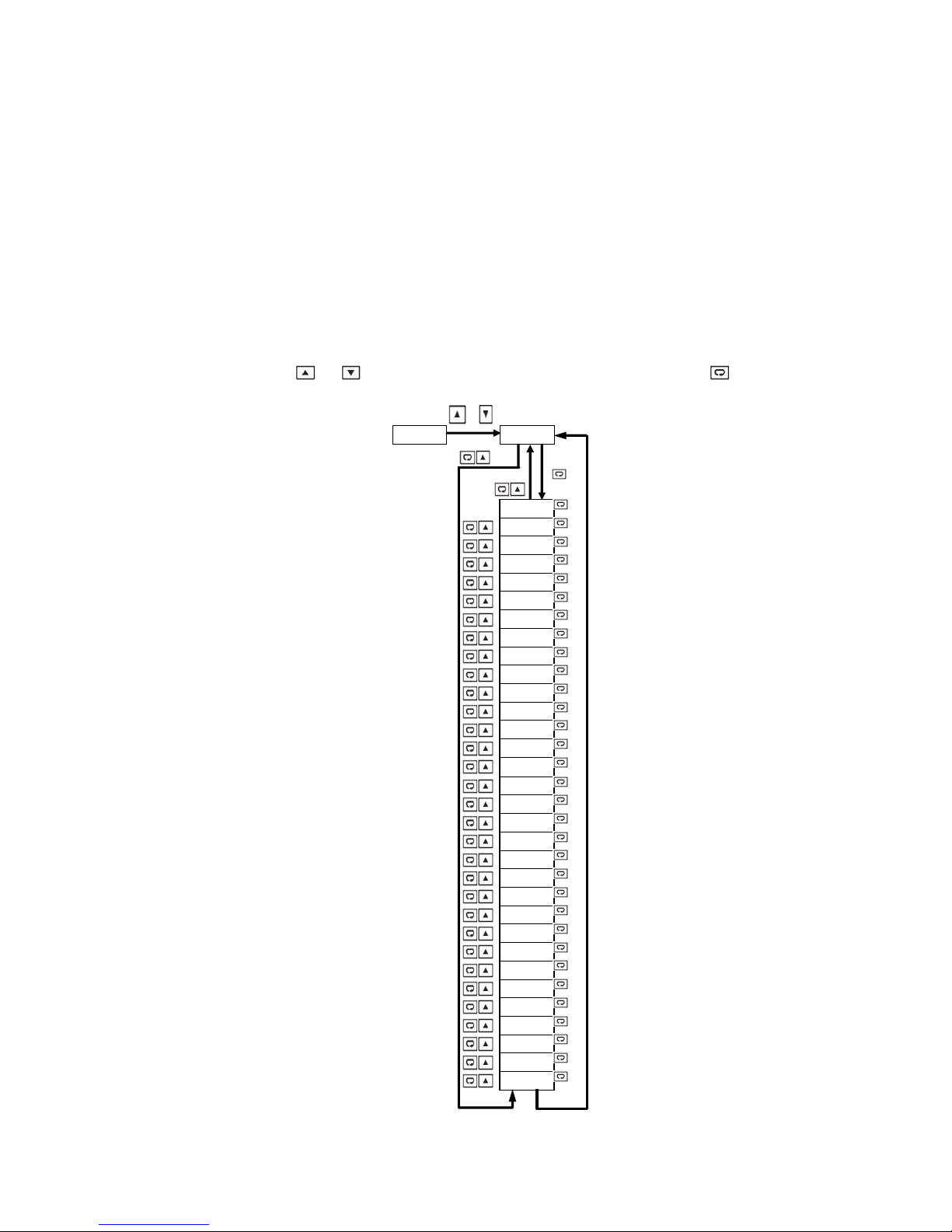
1.5 Menu Flowchart
User Menu
Setup
Menu
Manual Mode
Auto-Tuning Mode
Calibration Mode
To access
parameter
In the User Menu,
Refer to
Section 1.5.1
To access
parameter in
the Setup Menu,
Refer to
Section 1.5.2
To start
Manual Control
Mode, Refer to
Section 1.5.3
To start
Auto-Tuning
Mode, Refer to
Section 1.5.4
To access
Calibration Mode,
Refer to
Section 1.5.5
PV,SV
SP1
SP2
SP3
SP4
SP5
SP6
SP7
SFtR
CT1R
CT2R
DTM R
PASS
RUN
CYCR
STEP
TIMR
SEL1
SEL2
SEL3
SEL4
SEL5
SEL6
SEL7
SEL8
The Menu has been divided in to 5 groups. They are as follows:
1. User Menu
2. Setup Menu
3. Manual Mode Menu
4. Auto-Tuning Mode Menu
5. Calibration Mode Menu (not recommended, calibration section has been removed)
5 Sec 6.2 Sec 7.4 Sec 8.6 Sec 9.8 Sec
5 Sec 5 Sec 2 Sec Min
3 Sec Max
Press for the next parameter
Press and key to return to the previous parameter.
1.5.1 User Menu
The below user menu parameters are available depending on user selection.
Page 10 of 44
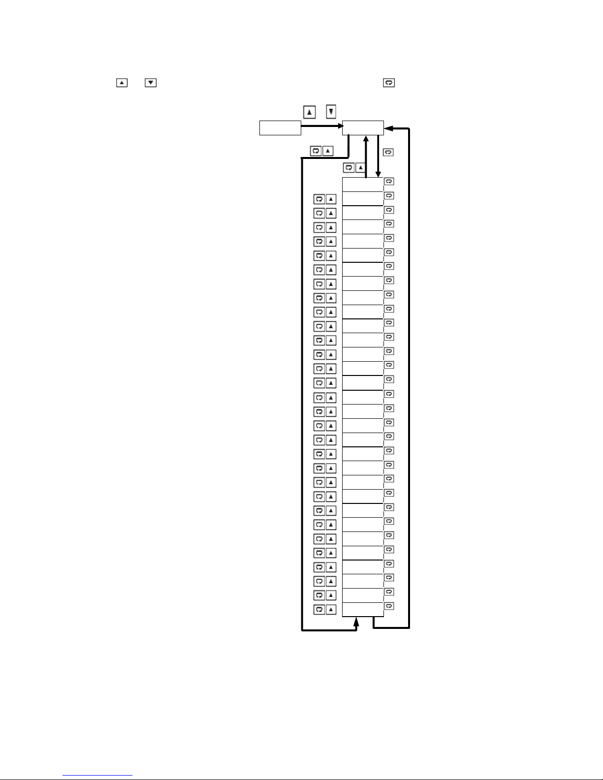
1.5.2 Setup Menu
or
SET bASE
OFS1
OFS2
OFS3
INPT
UNIT
DP
INLO
INHI
SP1L
SP1H
FILT
DISP
PB
TI
TD
RAMP
RR
RETY
RELO
REHI
RMSP
RINL
RINH
CODE
OFSTL
OFSTH
CALO
CAHI
SFT
SFL1
SFL2
SFtH
The setup menu has been categorized in to eight categories. They are listed below.
1.5.2.1 Basic Menu (bASE)
Use or key to get bASE in the lower display, then use the key to enter to basic
menu parameters.
1. Basic Menu
2. Output Menu
3. Alarm Menu
4. Event Input Menu
5. User Select Menu
6. Communication Menu
7. Current Transformer Input Menu
8. Profile Menu
Page 11 of 44
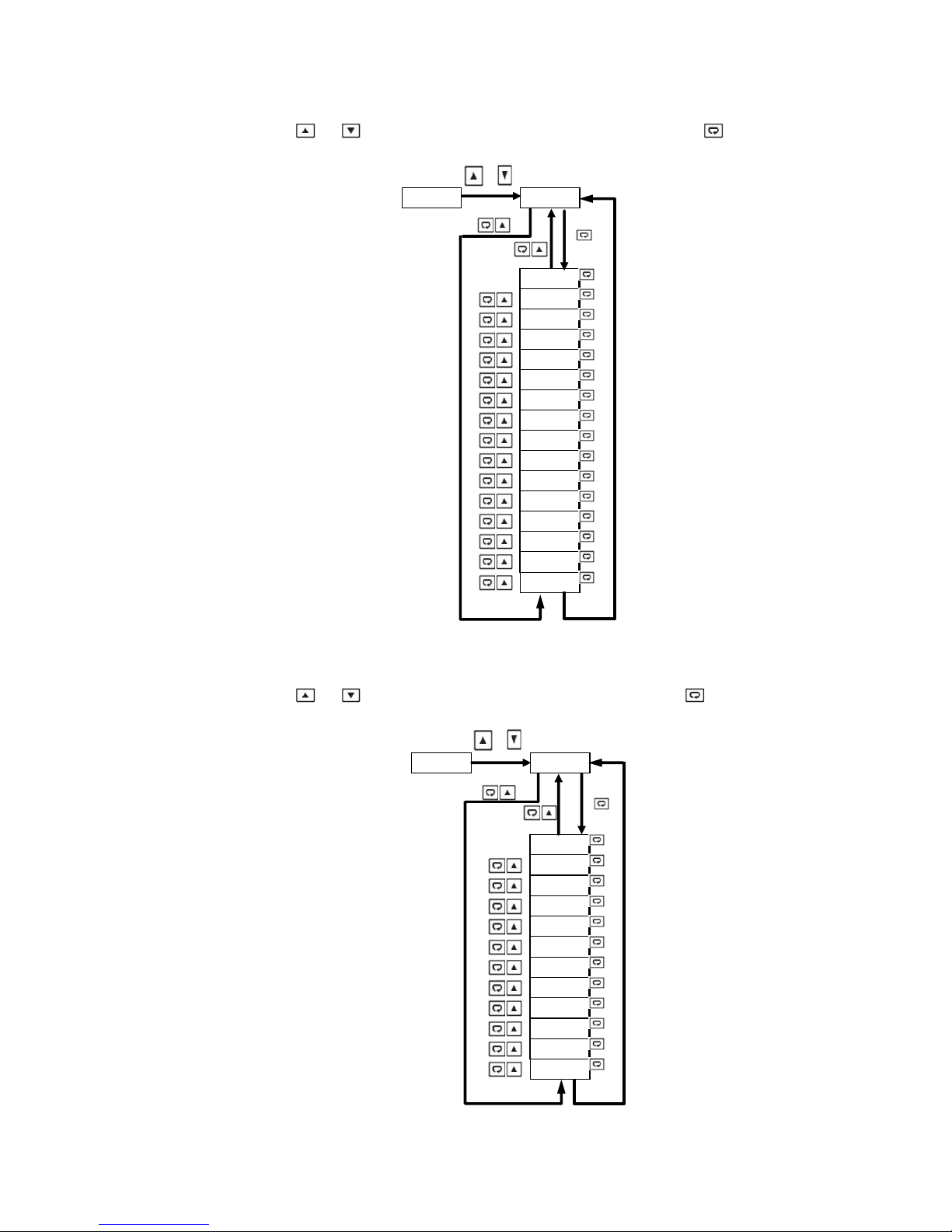
1.5.2.2 Output Menu (oUT)
or
SET OUT
OUT1
O1TY
O1FT
O1HY
CYC1
OFST
OUT2
O2TY
O2FT
CYC2
CPB
DB
PL1L
PL1H
PL2L
PL2H
or
SET EI
E1FN
SP2
E2FN
SP3
E3FN
SP4
E4FN
SP5
E5FN
SP6
E6FN
SP7
Use or key to get oUT in the lower display, then use the key to scroll through
output menu parameters.
1.5.2.3 Event Input Menu (EI)
Use or key to get EI in the lower display, then use the key to scroll through event
input menu parameters.
Page 12 of 44
1.5.2.4 Alarm Menu (ALRM)
or
SET ALRM
A1 FN
A1 MD
A1 HY
A1 FT
A1 SP
A1 DV
A1 DL
A2 OT
A2 FN
A2 MD
A2 HY
A2 FT
A2 SP
A2 DV
A2 DL
A3 OT
A3 FN
A3 MD
A3 HY
A3 FT
A3 SP
A3 DV
A3 DL
A4 OT
A4 FN
A4 MD
A4 HY
A4 FT
A4 SP
A4 DV
A4 DL
Use or key to get ALRM in the lower display, then use the key to scroll through alarm menu
parameters.
Page 13 of 44
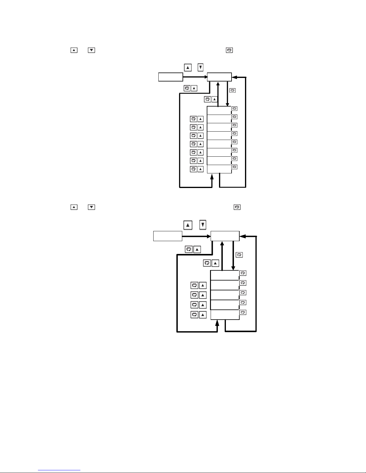
1.5.2.5 User Select Menu (SEL)
or
SET SEL
SEL1
SEL2
SEL3
SEL4
SEL5
SEL6
SEL7
SEL8
or
SET CoMM
ADD R
BAUD
DATA
PARI
ST OP
Use or key to get SEL in the lower display, then use the key to scroll through the “select” user
menu parameters.
1.5.2.6 Communication Menu (CoMM)
Use or key to get CoMM in the lower display, then use the key to scroll through the
communication menu parameters.
Page 14 of 44
 Loading...