

Tempco TEC-410 Instruction Manual
Instruction Manual
TEC-410
High Limit Control
Microprocessor Based Limit Controller
Manual TEC-410 Revision 8/2008
TEMPCO Electric Heater Corporation
607 N. Central Avenue • Wood Dale, IL 60191-1452 USA
Tel: 630-350-2252 • Toll Free: 800-323-6859
Fax: 630-350-0232 • E-mail: info@tempco.com
Web: www.tempco.com
Agency Approvals

Warning Symbol
This symbol calls attention to an operating procedure, practice, or the like which, if not correctly performed or adhered
to, could result in personal injury or damage to or destruction of part or all of the product and system. Do not proceed
beyond a warning symbol until the indicated conditions are
fully understood and met.
Using the Manual
• Installers . . . . . . . . . . . . . . . . . . . . . Read Chapter 1, 2
• System Designer . . . . . . . . . . . . . . . Read All Chapters
• Expert User . . . . . . . . . . . . . . . . . . . Read Page 11
Information in this user's manual is subject to change without notice.
Copyright © 2008, Tempco Electric Heater Corporation, all
rights reserved. No part of this publication may be reproduced, transmitted, transcribed or stored in a retrieval system, or translated into any language in any form by any
means without the written permission of Tempco Electric
Heater Corporation.
Contents
Page No.
Chapter 1 Overview
1-1 General . . . . . . . . . . . . . . . . . . . . . . . . . . . . . . . . . 1
1-2 Ordering Code . . . . . . . . . . . . . . . . . . . . . . . . . . . 1
1-3 Programming Port . . . . . . . . . . . . . . . . . . . . . . . . 2
1-4 Keys and Displays . . . . . . . . . . . . . . . . . . . . . . . . 2
1-5 Menu Overview . . . . . . . . . . . . . . . . . . . . . . . . . . 6
1-6 Menu Overview . . . . . . . . . . . . . . . . . . . . . . . . . . 7
1-7 Parameter Descriptions . . . . . . . . . . . . . . . . . . . . . 8
Chapter 2 Installation
2-1 Unpacking . . . . . . . . . . . . . . . . . . . . . . . . . . . . . . 11
2-2 Mounting . . . . . . . . . . . . . . . . . . . . . . . . . . . . . . . 11
2-3 Wiring Precautions . . . . . . . . . . . . . . . . . . . . . . . 11
2-4 Power Wiring . . . . . . . . . . . . . . . . . . . . . . . . . . . 12
2-5 Sensor Installation Guidelines . . . . . . . . . . . . . . 12
2-6 Thermocouple Input Wiring . . . . . . . . . . . . . . . . 12
2-7 RTD Input Wiring . . . . . . . . . . . . . . . . . . . . . . . . 13
2-8 Linear DC Input Wiring . . . . . . . . . . . . . . . . . . . 13
2-9 Event Input Wiring . . . . . . . . . . . . . . . . . . . . . . . 14
2-10 Output 1 Wiring . . . . . . . . . . . . . . . . . . . . . . . . 14
2-11 Output 2 Wiring . . . . . . . . . . . . . . . . . . . . . . . . 15
2-12 RS-485 . . . . . . . . . . . . . . . . . . . . . . . . . . . . . . . 16
2-13 RS-232 . . . . . . . . . . . . . . . . . . . . . . . . . . . . . . . 16
2-14 Retransmission . . . . . . . . . . . . . . . . . . . . . . . . . 16
Chapter 3 Programming
3-1 Process Input . . . . . . . . . . . . . . . . . . . . . . . . . . . 17
3-2 Limit Control . . . . . . . . . . . . . . . . . . . . . . . . . . . 17
3-3 Set Point Range . . . . . . . . . . . . . . . . . . . . . . . . . 18
3-4 PV Shift . . . . . . . . . . . . . . . . . . . . . . . . . . . . . . . . 13
3-5 Digital Filter . . . . . . . . . . . . . . . . . . . . . . . . . . . . 18
3-6 Process Alarms . . . . . . . . . . . . . . . . . . . . . . . . . . 19
3-7 Data communication . . . . . . . . . . . . . . . . . . . . . . 20
3-8 Process Variable (PV) Retransmission . . . . . . . . 20
3-9 Signal Conditioner DC Power Supply . . . . . . . . 21
3-10 Remote Reset . . . . . . . . . . . . . . . . . . . . . . . . . . 21
3-11 Remote Lock . . . . . . . . . . . . . . . . . . . . . . . . . . . 22
3-12 Limit Annunciator . . . . . . . . . . . . . . . . . . . . . . 22
3-13 Reference Data . . . . . . . . . . . . . . . . . . . . . . . . . 22
Chapter 4 Application . . . . . . . . . . . . . . . . . . . . 23
Chapter 5 Calibration . . . . . . . . . . . . . . . . . . . . . . 25
Chapter 6 Specifications . . . . . . . . . . . . . . . . . . . 27
Chapter 7 Modbus Communications
7-1 Functions Supported . . . . . . . . . . . . . . . . . . . . . . 29
7-2 Exception Responses . . . . . . . . . . . . . . . . . . . . . 30
7-3 Parameter Table . . . . . . . . . . . . . . . . . . . . . . . . . 30
7-4 Data Conversion . . . . . . . . . . . . . . . . . . . . . . . . . 32
7-5 Communication Examples. . . . . . . . . . . . . . . . . . 33
Appendix
A-1 Error Codes . . . . . . . . . . . . . . . . . . . . . . . . . . . . 34
A-2 Warranty . . . . . . . . . . . . . . . . . . . . . . . . . . . . . . . 35
Figures & Tables
Page No.
Figure 1.1 Access Overview . . . . . . . . . . . . . . . . . . . . 2
Figure 1.2 Front Panel Deplay . . . . . . . . . . . . . . . . . . 3
Figure 1.3 Power Up Sequence . . . . . . . . . . . . . . . . . 4
Figure 1.4 High Limit Operation . . . . . . . . . . . . . . . . 7
Figure 1.5 Low Limit Operation. . . . . . . . . . . . . . . . . 7
Figure 1.6 High/Low Limit Operation . . . . . . . . . . . . 7
Figure 2.1 Mounting Diagram . . . . . . . . . . . . . . . . . 11
Figure 2.2 Lead Termination . . . . . . . . . . . . . . . . . . . 11
Figure 2.3 Rear Terminal Connection Diagram . . . . 11
Figure 2.4 Power Supply Connections . . . . . . . . . . . 12
Figure 2.5 Thermocouple Input Wiring . . . . . . . . . . 12
Figure 2.6 RTD Input Wiring. . . . . . . . . . . . . . . . . . . 13
Figure 2.7 Linear Voltage Input Wiring . . . . . . . . . . 13
Figure 2.8 Linear Current Input Wiring . . . . . . . . . . 13
Figure 2.9 Event Input Wiring. . . . . . . . . . . . . . . . . . 14
Figure 2.10 Output 1 Wiring . . . . . . . . . . . . . . . . . . . 14
Figure 2.11 Output 2 Wiring . . . . . . . . . . . . . . . . . . . 15
Figure 2.12 RS-485 Wiring . . . . . . . . . . . . . . . . . . . . 16
Figure 2.13 RS-232 Wiring . . . . . . . . . . . . . . . . . . . . 16
Figure 2.14 Configuration of RS-232 Cable . . . . . . 16
Figure 2.15 Retransmission Wiring . . . . . . . . . . . . . 16
Figure 3.1 Conversion Curve for Linear Type
Process Value . . . . . . . . . . . . . . . . . . . . . . 17
Figure 3.2 Filter Characteristics. . . . . . . . . . . . . . . . . 18
Figure 3.3 Normal Process Alarm . . . . . . . . . . . . . . . 19
Figure 3.4 Latching Process Alarm . . . . . . . . . . . . . . 19
Figure 3.5 DC Power Supply Application . . . . . . . . . 20
Figure 3.6 Remote Reset Application . . . . . . . . . . . . 22
Figure 3.7 Remote Lock Application. . . . . . . . . . . . . 22
Figure 4.1 Over Temperature Protection with
Remote Reset . . . . . . . . . . . . . . . . . . . . . . 23
Figure 5.1 Flow Chart for Manual Calibration . . . . . 25
Figure 5.2 Cold Junction Calibration Setup . . . . . . . 25
Figure 5.3 RTD Calibration . . . . . . . . . . . . . . . . . . . . 26
Table 1.1 DIP Switch Configuration . . . . . . . . . . . . . 2
Table 1.2 Display Form of Characters . . . . . . . . . . . . 3
Table 6.1 Input Characteristics . . . . . . . . . . . . . . . . . 27
Table A.1 Error Codes and Corrective Actions . . . . . 34

1
Chapter 1 Overview
1–1 General
Power Input
4 = 90-250 Vac
5 = 11-26 Vac / Vdc
9 = Other
Signal Input
1 = Standard Input
Thermocouple: J, K, T, E,
B, R, S,N ,L, C, P
RTD: PT100 DIN,
PT100 JIS
mV0-60 mV
2 = Voltage: 0-1V
3 = Voltage: 0-10V
4 = 0-20 mA
5 = 0-5V
9 = Other
Output 1
1 = Relay: 2A / 240 Vac
2 = Pulsed voltage to drive
SSR drive:
5V/30mA
6 = Triac output
1A / 240 Vac,SSR
C = Pulsed voltage to drive
SSR drive:
14V/40mA )
9 = Other
Output 2
0 = None
1 = Form C Relay: 2A/240 Vac
2 = Pulsed voltage to drive SSR drive:
5V, /30mA
6 = Triac Output1A/240 Vac SSR
7 = RS-485 Data Interface,
TEC 920 only
8 = Isolated 20V @ 25 mA DC,
Output Power Supply
A = Isolated 12V @ 40 mA DC,
Output Power Supply
B = Isolated 5V @ 80 mA DC,
Output Power Supply
H = Other
Communication
0 = None
1 = RS-485 Interface
2 = RS-232 Interface
3 = Retransmit 4-20 mA/0-20 mA
4 = Retransmit 1-5 V/0-5 V
5 = Retransmit 0-10 V
9 = Other
TEC-410 –
Standard Mounting
1 = IP50 standard
2 = °C on faceplate
123456
1–2 Ordering Code
Accessories
TEC99001 = Smart Network Adapter for third party software,
converts 255 channels
of RS-485 or RS-422 to RS-232 Network
TEC99001 = Smart Network Adapter for programming port to
RS-232 interface
TEC99030 = Configuration Software
The TEC-410 limit control is an over temperature protection or a high limit safety device with a latching output that
removes power in an abnormal condition when the process
temperature is higher than the high limit set point or lower
than the low limit set point.
The unit is powered by 11–26 or 90–250VDC/VAC supply,
voltage incorporates a 3 amp form C relay for limit control,
a universal input which is fully programmable for PT100,
thermocouple types J, K, T, E, B, R, S, N, L, and 0-60mV,
and an option port is available for one of the following
functions: RS-232, RS-485 communication interface and
Retransmission. Alternative output options include SSR
drive and triac. The input signal is digitized by using an 18bit Analog to Digital converter. Its fast sampling rate (5
times/second) allows the TEC-410 to control fast processes
such as pressure and flow in addition to temperature.
RS-485 digital communication is available as an additional
option. This option allows the TEC-410 to be integrated
with a supervisory control system. An alarm output is
another option. A variety of alarm functions and alarm
modes can be programmed for a specific application. The
DC power supply output option is used for an external sensor or transmitter. The standard event input option can be
programmed for remote reset or remote lock out signal
input. The limit annunciator option can be used to control
an alarm buzzer.
Three different methods can be used to program the
TEC-410.
1. Use the keys on the front panel to program the unit
manually
2. Use a PC and setup software to program the unit via the
RS-485 port.
3. Use a PC and configuration software to program the
unit via the programming port.
High accuracy, maximum flexibility, fast response, and user
friendly operation are the main features of the TEC-410
high limit controller.
2
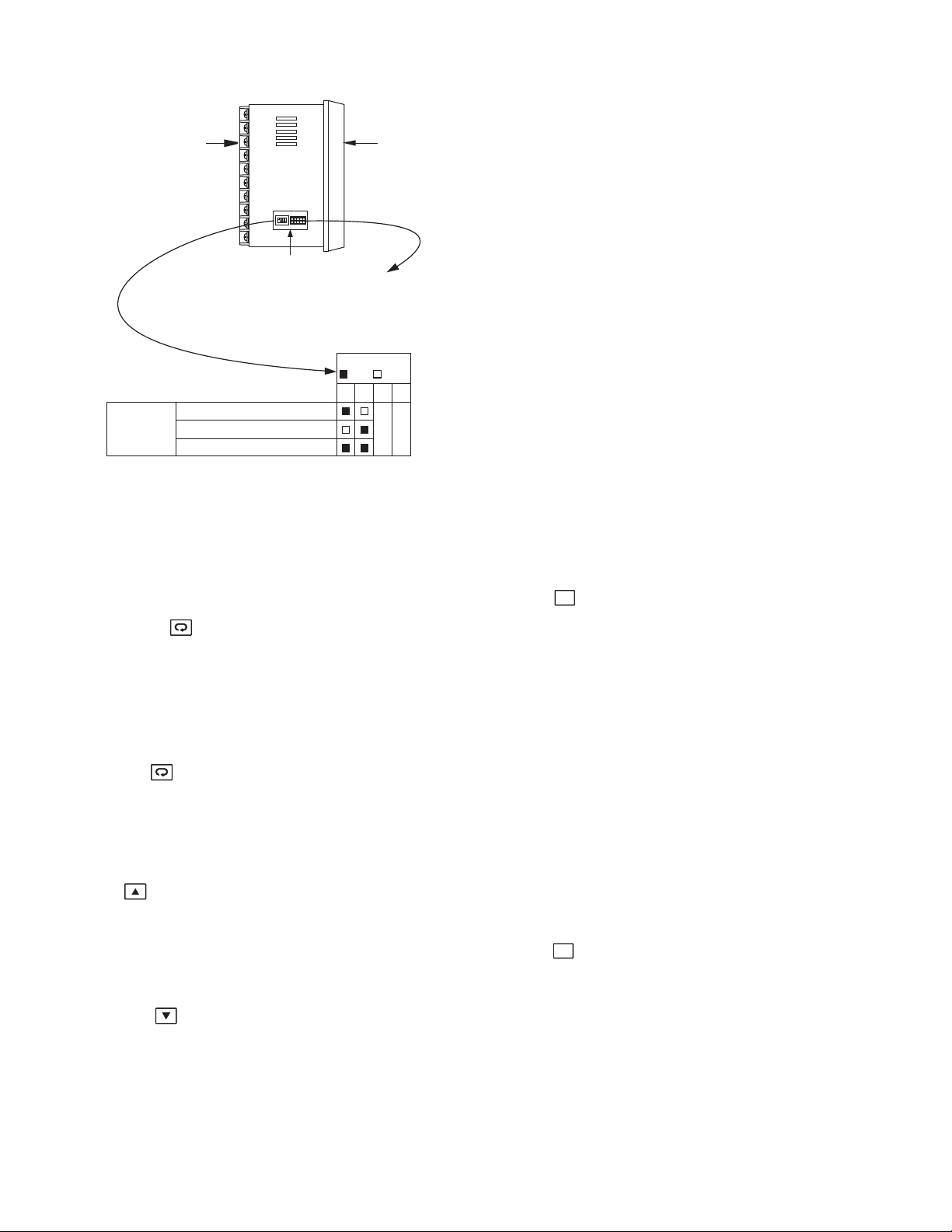
1–3 Programming Port and DIP Switch
The programming port is used for offline automatic setup and testing procedures only. Don't attempt to make any
connection to these pins when the unit
is actively being used in a control application.
Figure 1.1
Access Overview
RESET KEY:
This key is used to:
1. Revert the limit condition after the process is
within the limit.
2. Revert the display to the normal display.
3. Reset the latching alarm, once the alarm condition is removed.
4. Reset the limit annunciator.
Note:
If the RESET key is left pressed, only ONE reset
operation will
occur. If the unit subsequently goes into a state
where reset is
required again, the RESET key (or remote reset
contacts) must be
released (opened) and pressed (closed) again.
UNLOCK KEY 4 seconds Press the RESET
key for 4 seconds to enable up/down key
function,and the lock indicator will be extinguished.
However, this function is disabled when the EI
input pins are closed and remote lock is selected for
EIFN (Event Input Function). See section 3-11
R
R
1–4 Keys and Displays
KEYPAD OPERATION
SCROLL KEY:
1. Select a set point to be displayed.
2. Select a parameter to be viewed or adjusted.
3. Advance display from a parameter code to the
next parameter code.
ENTER KEY : 4 seconds, 6 seconds.
Press the enter key for 4 seconds to enter the
setup menu.
Press the enter key for 6 seconds to enter the
calibration mode.
UP KEY:
This key is used to increase the selected
parameter value when the lock indicator is
off.
DOWN KEY:
This key is used to decrease the selected
parameter value when the lock indicator is
off.
Table 1.1
DIP Switch Configuration
Rear
Terminal
Front
Panel
ON DIP
1 2 3 4
Access Hole
The programming port is used to connect to SNA12A
for automatic programming, also can be connected to
ATE system for automatic testing & calibration.
DIP Switch
:ON :OFF
12
Input
Select
TC, RTD, mV
0-1V, 0-10V
0-20 ma
34

3
Table 1.2
Display Form of Characters
The reference data are reset as long as the reset key
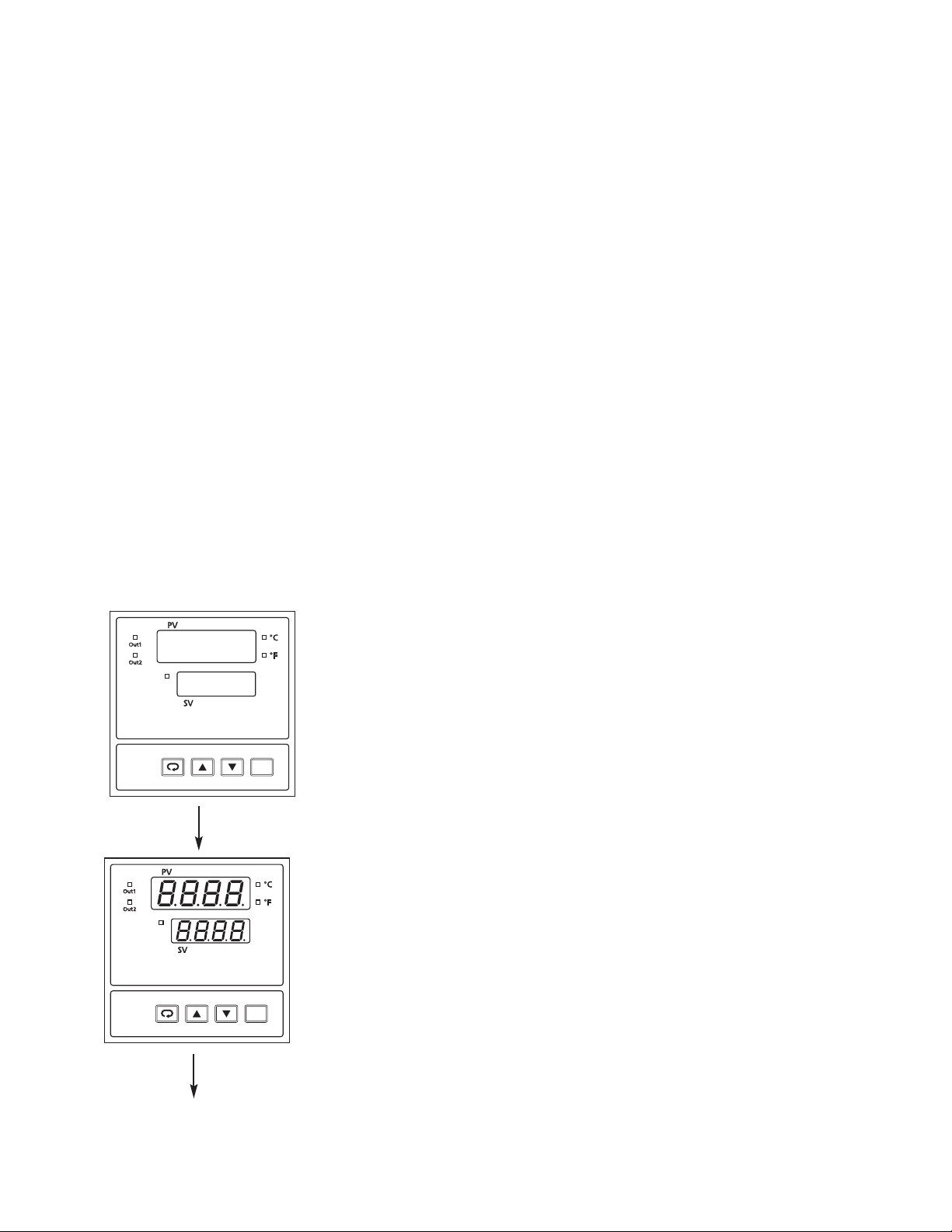
Figure 1.2
Front Panel Display
How to display a 5-digit number:
For a number with a decimal point, the display will be shifted one digit to the right:
-199.99 will be displayed as -199.9, 4553.6 will be displayed as 4553
For a number without a decimal point, the display will be divided into two alternating phases:
-19999 will be displayed as
45536 will be displayed as
-9999 will be displayed as
is pressed for 4 seconds. See section 3-13.
Output 1 ~ 2 Indicator
Out1
Out2
Upper Display, to display process value,
menu symbol and error code etc.
Process Unit Indicator
Lock
Lock
Status
Indicator
A
B
C
c
Dh
: Indicates Abstract Characters
TEMPCO
Limit Control
E
F
G
H
I
J
K
L
M
TEC-410
R
N
O
S
T
PU
Q
R
V
W
Lower Display, to display set point
value, parameter value etc.
4 Buttons for ease of control
setup and set point adjustment.
X
Y
Z
?
=
4
NORMAL DISPLAY
During normal operation, the unit will display the process value and the word SAFE.
ABNORMAL DISPLAY
Whenever the process is outside the normal range, the lower display will display the limit
set point value, instead of displaying the word SAFE.
SENSOR BREAK DISPLAY
If a break is detected in the sensor circuit, the display will show:
SENB
A-D FAILURE DISPLAY
If failure is detected in the A-D converter circuit, the display will show:
AD.ER
R
LIMIT CONTROL
R
LIMIT CONTROL
All segments of display and indicators are left
off for 0.5 second.
All segments of display and indicators are lit
for 1.5 second.
Figure 1.3
Power Up Sequence
POWER UP SEQUENCE
Lock
TEMPCO
TEC-410
Lock
LIMIT CONTROL
TEMPCO
TEC-410
LIMIT CONTROL
5
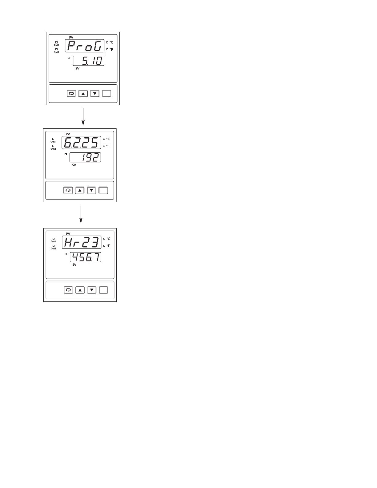
Display program code of the product for 1.5 seconds.
The example shows program no.5 with version 10.
Display Date Code for 1.5 seconds.The example shows Year
2006 (6), Month February (2), Date 25th. This means that the
product is produced on February 25th, 2006. Note that the month
code A is for October, B is for November and C is for December.
Display the serial number (001-999)for 1.5 seconds.
Display the hours used for 1.5 seconds. The example shows that the
unit has been used for 23456.7 hours since production.
Lock
R
LIMIT CONTROL
R
LIMIT CONTROL
R
LIMIT CONTROL
Verify that all electrical connections have been made properly before applying power to the unit.
During power up, a self-test procedure will be performed within 6.5 seconds.
During the self-test period all outputs are left off. When the self-test procedure is complete, the unit will revert to normal operation.
TEMPCO
TEC-410
TEMPCO
TEC-410
Lock
Lock
LIMIT CONTROL
LIMIT CONTROL
TEMPCO
TEC-410
LIMIT CONTROL
6
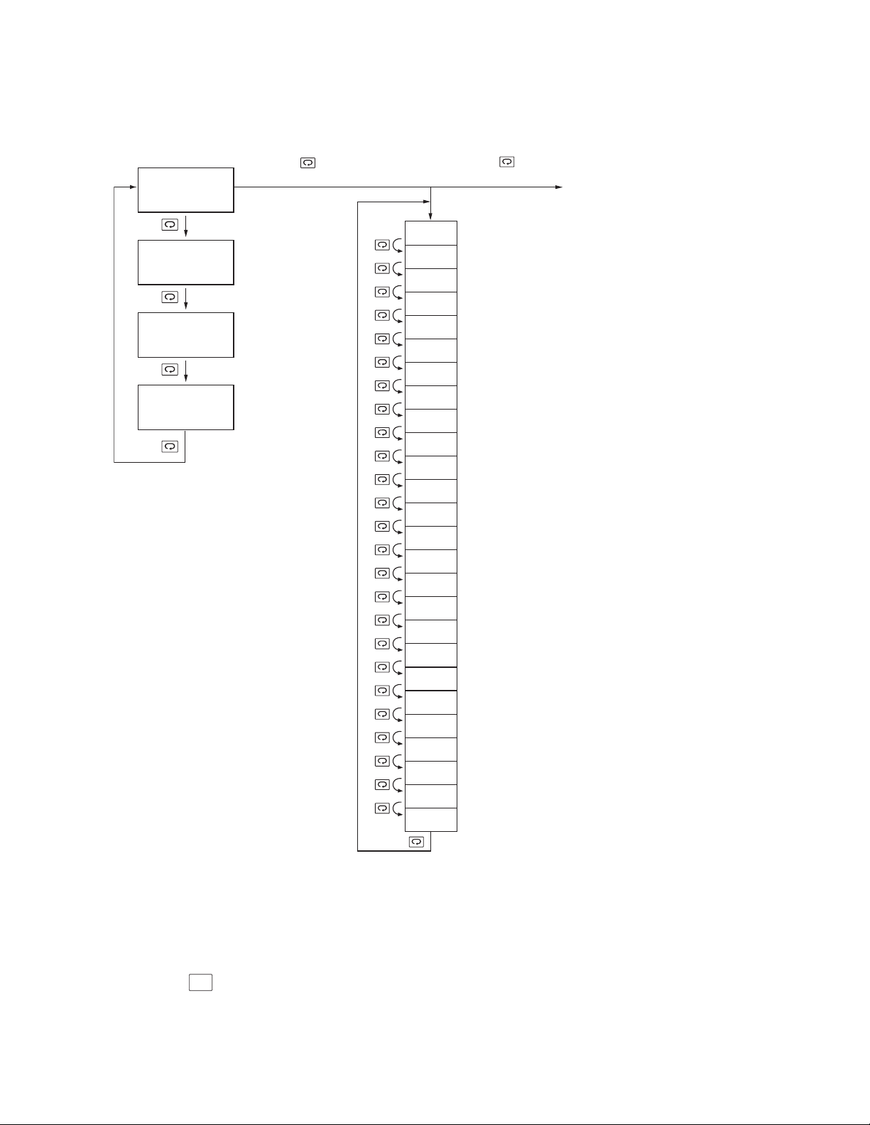
1–5 Menu Overview
Note 1. The flow charts show a complete listing of parameters. For the actual application,
the number of available parameters are dependent on the setup conditions, and
should be less than that shown in the flow charts.
Note 2. Press key for 4 seconds to enable up/down key function and extinguish the
LOCK indicator.
PV Value
SP1 or SAFE
Press
for 4 sec.
Setup Mode
Press
for 2 sec.
Calibration Mode
HSP1 Value
__ __ __ __
LSP1 Value
__ __ __ __
SP2 Value
__ __ __ __
High limit
setpoint 1
value
Low limit
setpoint 1
value
Set point 2
value
INPT
UNIT
RESO
IN.LO
IN.HI
SHIF
FILT
OUT1
O1.HY
HSP. L
HSP. H
LSP. L
LSP. H
OUT2
ADDR
BAUD
PARI
AL.FN
AL.MD
AL.HY
AL.FT
EIFN
DISP
PV.HI
PV.LO
T. AB N
Input type
Process unit
Display resolution
Low scale value for linear
input
High scale value for linear
input
PV shift (offset) value
PV filter time constant
Output 1 function
Output 1 hysteresis value
Lower limit of HSP1
Upper limit of HSP1
Lower limit of LSP1
Upper limit of LSP1
Output 2 function
Address for digital
communication
Baud rate
Parity bit
Alarm function
Alarm mode
Alarm hysteresis value
Alarm failure transfer
Event input function
Normal display format
Max. historical PV
Min. historical PV
Abnormal time
R

7
Figure 1.4
High Limit Operation
HIGH LIMIT OPERATION
If Hi. is selected for OUT1, the unit will perform
high limit control. When power is applied the OUT1
relay is de-energized. After the 6.5 second self-test
period, if the process is below the high limit set point
(HSP1) the output 1 relay will be energized and the
OP1 indicator will go off.If the process goes above
the high limit set point, the relay will be de-energized, the OP1 indicator will go on, and the display
will show the process value. After the process falls
below the high limit set point and the RESET key is
pressed or the remote reset input is applied, the relay
will be energized and the OP1 indicator will go off.
1–6 Limit Control Operation
LOW LIMIT OPERATION
If Lo. is selected for OUT1, the unit will perform low
limit control. When power is applied the OUT1 relay is
de-energized. After the 6.5 second self-test period, if the
process is above the low limit set point (LSP1) the output 1 relay will be energized and the OP1 indicator will
go off.If the process goes below the low limit set point,
the relay will be de-energized, the OP1 indicator will go
on, and the display will show the process value. After
the process rises above the low limit set point and the
RESET key is pressed or the remote reset input is
applied, the relay will be energized and the OP1 indicator will go off.
Figure 1.5
Low Limit Operation
HIGH/LOW LIMIT OPERATION
If Hi.Lo is selected for OUT1, the unit will perform high/low limit control. When power is
applied, the OUT1 relay is de-energized. After the
6.5 second self-test period, if the process is below
the high limit set point (HSP1) and above the low
limit set point (LSP1), the output 1 relay will be
energized and the OP1 indicator will go off.
If the process goes above the high limit set point
or below the low limit set point, the relay will be
de-energized, the OP1 indicator will go on, and
the display will show the process value. After the
process is within the normal operation range, and
the RESET key is pressed or the remote reset
input is applied, the relay will be energized and
the OP1 indicator will go off.
LSP1 + O1.HY
HSP1
LSP1
HSP1 – O1.HY
ON
OFF
OUT1 Relay
A, B, C, D, E, F =Reset is applied
O1.HY= Output1 hysteresis
ABC D EF
Figure 1.6
High/Low Limit Operation
PV
HSP1
HSP1 – O1.HY
OUT1 Relay
ON
OFF
AB C
A, B ,C = Reset is applied
O1.HY = Output1 hysteresis
LSP1 + O1.HY
LSP1
OUT1 Relay
ON
OFF
AB C
A, B ,C = Reset is applied
O1.HY = Output1 hysteresis

8
Parameter
Notation
Default
Value
Parameter Description
(Refer to Page:)
Range
Input sensor
selection
(Page 11 & 23)
1
(0)
Low Limit Set point 1
Low: LSP.L High: LSP. H
0.0°C
(32.0°F)
High Limit Set point 1
Low: HSP.L High: HSP. H
100.0°C
(212.0°F)
Process unit
0
(1)
Display Resolution
1
Low scale value for
Iinear Input (Page 11)
High scale value for
Iinear Input (Page 11)
Low: -19999 High: IN.HI
Low: IN.LO High: 45536
0
-200.0°C
(-360.0°F)
0.0
Low:
200.0°C
(360.0°F)
High:
100.0
PV Filter Time
Constant
(Page 15)
2
PV Shift (offset)
Value
0) 0 : 0 second time constant
1) 0.2 : 0.2 second time constant
2) 0.5 : 0.5 second time constant
3) 1 : 1 second time constant
4) 2 : 2 seconds time constant
5) 5 : 5 seconds time constant
6) 10 : 10 second
s time constant
7) 20 : 20 seconds time constant
8) 30 : 30 seconds time constant
9) 60 : 60 seconds time constant
0) NO.DP : No decimal point
1) 1-DP : 1 decimal digit
2) 2-DP : 2 decimal digits
3) 3-DP : 3 decimal digits
0) J-TC : J type thermocouple
1) K-TC : K type thermocouple
2) T-TC : T type thermocouple
3) E-TC : E type thermocouple
4) B-TC : B type thermocouple
5) R-TC : R type thermocouple
6) S-TC : S type thermocouple
7) N-TC : N type thermocouple
8) L-TC : L type thermocouple
9) C-TC : C type thermocouple
10) P-TC
: P type thermocouple
11) PTDN : PT 100 ohms DIN curve
12) PTJS : PT 100 ohms JIS curve
13) 4-20 : 4 - 20 mA linear current
input
14) 0-20 : 0 - 20 mA linear current
input
15) 0-60 : 0 - 60 mV linear millivolt
input
16) 0-1V: 0-1V linear voltage input
17) 0-5V: 0-5V linear voltage input
18) 1-5V: 1-5V linear voltage input
19) 0-10: 0-10V linear voltage input
0) QC: Degree C unit
1) QF: Degree F unit
2) PU: Process unit
HSP1
HSP1
LSP1
LSP1
Set point 2 Value for
Output 2
Low: -19999 High: 45536
90.0°C
(194.0°F)
SP2
SP2
RESO
RESO
INLO
INLO
INPE
INPT
INHI
INHI
SHIF
SPIF
Output 1 Function
UNIT
UNIT
FILT
FILT
OUT1
OUT1
2) HI. : High limit control
3) LO. : Low limit control
4) HI.LO : High/Low limit control
2
1–7 Parameter Descriptions

9
Communication
function
(Page 23)
0) NONE: No communication
1) RTU : Modbus RTU
mode protocol
2) 4-20: 4-20 mA DC
transmission output
3) 0-20: 0 - 20 mA DC
transmission output
4) 0-5V: 0 - 1V DC
transmission output
5) 1-5V: 0 - 5V DC
transmission output
6) 0-10: 1 - 5V DC
transmission output
1
COMM
COMM
Baud rate of digital
communication
(Page 25)
0) 0.3: 0.3 Kbits/s baud rate
1) 0.6: 0.6 Kbits/s baud rate
2) 1.2: 1.2 Kbits/s baud rate
3) 2.4: 2.4 Kbits/s baud rate
4) 4.8: 4.8 Kbits/s baud rate
5) 9.6: 9.6 Kbits/s baud rate
6) 14.4: 14.4 Kbit
s/s baud rate
7) 19.2: 19.2 Kbits/s baud rate
8) 28.8: 28.8 Kbits/s baud rate
9) 38.4: 38.4 Kbits/s baud rate
Parity bit of digital
communication
0) EVEN: 8 bit even parity
1) ODD: 8 bit odd parity
2) NONE: 8 bit none parity
Analog/Retransmission
Output Function
0) PV: Process Value
1) HSP1: High Limit Set point 1
2) LSP1: Low Limit Set point 1
BAUD
BAUD
PARI
PAR I
AOFN
AOFN
Low: -19999 High: 45536
0.0°C
(32.0°F)
Analog Output Low
Scale Value
AOLO
AOLO
Low: -19999 High: 45536
100.0°C
(212.0°F)
Analog Output High
Scale Value
AOHI
AOHI
Output 1 Hysteresis
Value
Low: 0.1 High: 10.0°C (18.0°F)
.1
O1.HY
O1.HY
Lower Limit of HSP1
Low: -19999 High: HSP. H
0.0°C
(32.0°F)
HSP.L
HSP. L
Upper Limit of HSP1
Low: HSP.L High: 45536
1000.0°C
(1832.0°F)
HSP.H
HSP. H
Lower Limit of LSP1
Low: -19999 High: LSP. H
-100.0°C
(-148.0°F)
LSP.L
LSP. L
Upper Limit of LSP1
Low: :LSP.L High: 45536
0.0°C
(32.0°F)
LSP.H
LSP. H
OUT2
OUT2
Output 2 Function
0) NONE : No Function
1) DCPS : DC power supply output
2) ALN : Alarm Output
3) L-AN : Limit Annunciator
2
Parameter
Notation
Default
Valu e
Parameter Description
(Refer to Page:)
Range

10
Historical Max. value of PV
(Page 23)
—
PV.HI
PV.HI
Historical Min. value of PV
(Page 25)
Accumulated Time during
abnormal condition
PV.LO
PV.LO
T.ABN
T.ABN
Alarm Function
6) P.VH.A : Process value high alarm
7) P.VL.A : Process value low alarm
6
AL.FN
AL.FN
Alarm mode
6) NORM : Normal alarm action
7) LTch : Latching alarm action
0
AL.MD
AL.MD
Alarm hystersis value
Low: 0.1 High: 10°C (18°F)
0.1
AL.HY
AL.HY
Alarm failure transfer
0) OFF : Alarm Output goes off as
unit fails
1) ON : Alarm Output goes on as
unit fails
1
AL.FT
AL.FT
Event input function
0
EIFN
EIFN
DISP
DISP
Normal display format
0) SAFE : Display SAFE
1) HSP1 : Display the value of HSP1
2) LSP1 : Display the value of LSP1
0
Parameter
Notation
Default
Valu e
Parameter Description
(Refer to Page:)
Range
0) NONE : No event function
1) REST : Remote reset for output 1,
output 1 on
2) LOCK : Remote lock for the unit
Low: -19999 High: 45536
Low: -19999 High: 45536
Low: 0 High: 6553.5 minutes
—
—
 Loading...