

Tempco tec-220, tec-920 Instruction Manual

Instruction Manual
TEC-220 and TEC-920
Auto-Tune Fuzzy / PID Process
Temperature Controller
Serving Industry Since 1972
Agency Approvals
TEMPCO Electric Heater Corporation
607 N. Central Avenue • Wood Dale, IL 60191-1452 USA
Tel: 630-350-2252 • Toll Free: 800-323-6859
Fax: 630-350-0232 • E-mail: info@tempco.com
Web: www.tempco.com
Manual TEC-220/920 Revision 9/2016

NOTES

Warning Symbol
This symbol calls attention to an operating procedure, practice, or
the like which, if not correctly performed or adhered to, could
result in personal injury or damage to or destruction of part or all
of the product and system. Do not proceed beyond a warning symbol until the indicated conditions are fully understood and met.
Using the Manual
Installers . . . . . . . . . . . . . . . . . . . . . . . . . . . Read Chapter 1, 2
System Designer . . . . . . . . . . . . . . . . . . . . . Read All Chapters
Expert User . . . . . . . . . . . . . . . . . . . . . . . . . Read Page 11
Contents
Page No.
Chapter 1 Overview
1-1 General . . . . . . . . . . . . . . . . . . . . . . . . . . . . . . . . . . . . . 1
1-2 Ordering Code . . . . . . . . . . . . . . . . . . . . . . . . . . . . . . . 2
1-3 Programming Port . . . . . . . . . . . . . . . . . . . . . . . . . . . . 2
1-4 Keys and Displays . . . . . . . . . . . . . . . . . . . . . . . . . . . . 3
1-5 Menu Overview . . . . . . . . . . . . . . . . . . . . . . . . . . . . . . 4
1-6 Parameter Descriptions . . . . . . . . . . . . . . . . . . . . . . . . . 5
Chapter 2 Installation
2-1 Unpacking . . . . . . . . . . . . . . . . . . . . . . . . . . . . . . . . . . . 7
2-2 Mounting . . . . . . . . . . . . . . . . . . . . . . . . . . . . . . . . . . . 7
2-3 Wiring Precautions . . . . . . . . . . . . . . . . . . . . . . . . . . . . 7
2-4 Power Wiring . . . . . . . . . . . . . . . . . . . . . . . . . . . . . . . . 8
2-5 Sensor Installation Guidelines . . . . . . . . . . . . . . . . . . . 8
2-6 Sensor Input Wiring . . . . . . . . . . . . . . . . . . . . . . . . . . . 8
2-7 Control Output Wiring . . . . . . . . . . . . . . . . . . . . . . . . . 8
2-8 Alarm Wiring . . . . . . . . . . . . . . . . . . . . . . . . . . . . . . . . 10
2-9 Data Communication . . . . . . . . . . . . . . . . . . . . . . . . . . 10
Chapter 3 Programming
3-1 Lockout . . . . . . . . . . . . . . . . . . . . . . . . . . . . . . . . . . . . 11
3-2 Signal Input . . . . . . . . . . . . . . . . . . . . . . . . . . . . . . . . . 11
3-3 Control Outputs . . . . . . . . . . . . . . . . . . . . . . . . . . . . . . 11
3-4 Alarm . . . . . . . . . . . . . . . . . . . . . . . . . . . . . . . . . . . . . . 13
3-5 Configuring the Display . . . . . . . . . . . . . . . . . . . . . . . 14
3-6 Ramp . . . . . . . . . . . . . . . . . . . . . . . . . . . . . . . . . . . . . . 14
3-7 Dwell Timer . . . . . . . . . . . . . . . . . . . . . . . . . . . . . . . . . 14
3-8 PV Shift . . . . . . . . . . . . . . . . . . . . . . . . . . . . . . . . . . . . 15
3-9 Digital Filter . . . . . . . . . . . . . . . . . . . . . . . . . . . . . . . . 15
3-10 Failure Transfer . . . . . . . . . . . . . . . . . . . . . . . . . . . . . 15
3-11 Auto-tuning . . . . . . . . . . . . . . . . . . . . . . . . . . . . . . . . 16
3-12 Manual tuning . . . . . . . . . . . . . . . . . . . . . . . . . . . . . . 16
3-13 Manual Control . . . . . . . . . . . . . . . . . . . . . . . . . . . . . 17
3-14 Data communication. . . . . . . . . . . . . . . . . . . . . . . . . . 17
3-15 Process Variable (PV) Retransmission. . . . . . . . . . . . 17
Chapter 4 Applications
4-1 Heat Only Control With Dwell Timer . . . . . . . . . . . . . 19
4-2 Cool Only Control . . . . . . . . . . . . . . . . . . . . . . . . . . . . 19
4-3 Heat-Cool Control . . . . . . . . . . . . . . . . . . . . . . . . . . . . 20
Chapter 5 Calibration . . . . . . . . . . . . . . . . . . 21
Chapter 6 Specifications . . . . . . . . . . . . . 23
Chapter 7 Modbus Communications
7-1 Functions Supported . . . . . . . . . . . . . . . . . . . . . . . . . . 25
7-2 Exception Responses . . . . . . . . . . . . . . . . . . . . . . . . . . 26
7-3 Parameter Table . . . . . . . . . . . . . . . . . . . . . . . . . . . . . . 26
7-4 Data Conversion . . . . . . . . . . . . . . . . . . . . . . . . . . . . . . 28
7-5 Communication Examples . . . . . . . . . . . . . . . . . . . . . . 29
Appendix
A-1 Error Codes . . . . . . . . . . . . . . . . . . . . . . . . . . . . . . . . . 30
A-2 Warranty . . . . . . . . . . . . . . . . . . . . . . . . . . . . . . . . . . . 31
NOTE:
It is strongly recommended that a process should incorporate a LIMIT CONTROL like TEC-910 which will shut
down the equipment at a preset process condition in order to
preclude possible damage to products or system.
Information in this user's manual is subject to change without
notice.
Copyright © 2010, Tempco Electric Heater Corporation, all
rights reserved. No part of this publication may be reproduced,
transmitted, transcribed or stored in a retrieval system, or translated into any language in any form by any means without the
written permission of Tempco Electric Heater Corporation.
Figures & Tables
Page No.
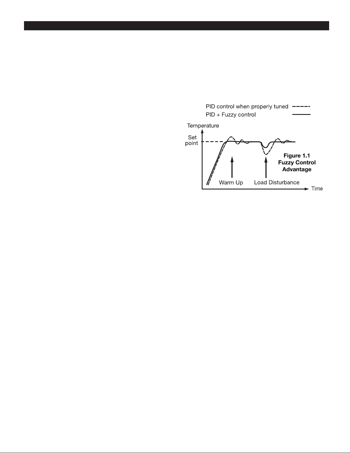
Figure 1.1 Fuzzy Control Advantage. . . . . . . . . . . . . . . . . . 1
Figure 1.2 Programming Port Overview . . . . . . . . . . . . . . . 2
Figure 1.3 Front Panel Description . . . . . . . . . . . . . . . . . . 3
Figure 1.4 Display in Initial Stage. . . . . . . . . . . . . . . . . . . . 3
Figure 2.1 Mounting Dimensions and Panel Cutout . . . . . . 7
Figure 2.2 Lead Termination for TEC-920 . . . . . . . . . . . . . 7
Figure 2.3 Lead Termination for TEC-220 . . . . . . . . . . . . . 7
Figure 2.4 Rear Terminal Connection for TEC-220 . . . . . . 8
Figure 2.5 Rear Terminal Connection for TEC-920 . . . . . . 8
Figure 2.6 Power Supply Connections . . . . . . . . . . . . . . . . 8
Figure 2.7 Sensor Input Wiring . . . . . . . . . . . . . . . . . . . . . 8
Figure 2.8 Output 1 Relay or Triac (SSR) to
Drive Load . . . . . . . . . . . . . . . . . . . . . . . . . . . . 8
Figure 2.9 Output 1 Relay or Triac (SSR) to
Drive Contactor . . . . . . . . . . . . . . . . . . . . . . . . . 8
Figure 2.10 Output 1 Pulsed Voltage to Drive SSR . . . . . . 9
Figure 2.11 Output 1 Linear Current . . . . . . . . . . . . . . . . . . 9
Figure 2.12 Output 1 Linear Voltage . . . . . . . . . . . . . . . . . . 9
Figure 2.13 Output 2 Relay or Triac (SSR) to
Drive Load . . . . . . . . . . . . . . . . . . . . . . . . . . . . 9
Figure 2.14 Output 2 Relay or Triac (SSR) to
Drive Contactor . . . . . . . . . . . . . . . . . . . . . . . . 9
Figure 2.15 Output 2 Pulsed Voltage to Drive SSR . . . . . . 9
Figure 2.16 Output 2 Linear Current . . . . . . . . . . . . . . . . . . 9
Figure 2.17 Output 2 Linear Voltage . . . . . . . . . . . . . . . . . 9
Figure 2.18 Alarm Output to Drive Load . . . . . . . . . . . . . 10
Figure 2.19 Alarm Output to Drive Contactor . . . . . . . . . . 10
Figure 2.20 RS-485 Wiring . . . . . . . . . . . . . . . . . . . . . . . . 10
Figure 2.21 RS-232 Wiring . . . . . . . . . . . . . . . . . . . . . . . . 10
Figure 2.22 Configuration of RS-232 Cable . . . . . . . . . . . 10
Figure 3.1 Conversion Curve for Linear Type
Process Value . . . . . . . . . . . . . . . . . . . . . . . . . . 11
Figure 3.2 Heat Only ON-OFF Control . . . . . . . . . . . . . . . 12
Figure 3.3 Output 2 Deviation High Alarm . . . . . . . . . . . . 13
Figure 3.4 Output 2 Process Low Alarm . . . . . . . . . . . . . . 13
Figure 3.5 RAMP Function . . . . . . . . . . . . . . . . . . . . . . . . 14
Figure 3.6 Dwell Timer Function . . . . . . . . . . . . . . . . . . . . 14
Figure 3.7 PV Shift Application . . . . . . . . . . . . . . . . . . . . . 15
Figure 3.8 Filter Characteristics . . . . . . . . . . . . . . . . . . . . . 15
Figure 3.9 Effects of PID Adjustment . . . . . . . . . . . . . . . . 16
Figure 4.1 Heat Control Example. . . . . . . . . . . . . . . . . . . . 19
Figure 4.2 Cooling Control Example . . . . . . . . . . . . . . . . . 19
Figure 4.3 Heat-Cool Control Example . . . . . . . . . . . . . . . 20
Figure 5.1 RTD Calibration . . . . . . . . . . . . . . . . . . . . . . . . 21
Figure 5.2 Cold Junction Calibration Setup . . . . . . . . . . . . 22
Table 1.1 Display Form of Characters . . . . . . . . . . . . . . . . 3
Table 3.1 Heat-Cool Control Setup Value . . . . . . . . . . . . . 11
Table 3.2 PID Adjustment Guide . . . . . . . . . . . . . . . . . . . . 16
Table A.1 Error Codes and Corrective Actions . . . . . . . . . 30
Appendix
Warranty . . . . . . . . . . . . . . . . . . . . . . . . . . . . . . . . . . . . . . . 31
Returns . . . . . . . . . . . . . . . . . . . . . . . . . . . . . . . . . . . . . . . . 31

NOTES
Chapter 1 Overview
1–1 General
Tempco’s TEC-220 and TEC-920 Fuzzy Logic plus PID microprocessor-based controllers incorporate a bright easy to read 4digit LED display indicating process value or set point. Fuzzy
Logic technology enables a process to reach a predetermined set
point in the shortest time with a minimum of overshoot during
power-up or external load disturbances.
The TEC-220 is a 1/32 DIN size panel mount controller. The
TEC-920 is a 1/16 DIN size panel mount controller. These units
are powered by 11–26 or 90–250 VDC/VAC 50/60 Hz supply,
incorporating a 2 Amp control relay output as a standard. The
second output can be used as a cooling control, an alarm or a
dwell timer. Either output can use a triac, 5V logic output, linear
current or linear voltage to drive an external device. There are six
types of alarms or a dwell timer that can be configured for the
second output. The units are fully programmable for PT100 RTD
and thermocouple types J, K, T, E, B, R, S, N, and L with no need
to modify the unit. The input signal is digitized by using an 18bit A to D converter. Its fast sampling rate allows the unit to control fast processes.
Digital communications RS-485 is available for the TEC-220 or
TEC-920. RS-232 is available for the TEC-220 only. These
options allow the units to be integrated with supervisory control
systems and software.
A programming port is available for automatic configuration,
without the need to access the keys on the front panel.
By using proprietary Fuzzy modified PID technology, the control loop will minimize overshoot and undershoot in a short time.
The following diagram is a comparison of results with and without Fuzzy technology.
High accuracy
This series is manufactured with custom
designed ASIC (Application Specific
Integrated Circuit) technology which
contains an 18-bit A to D converter for
high resolution measurement (true 0.1°F
resolution for thermocouple and RTD)
and a 15-bit D to A converter for linear
current or voltage control output. The
ASIC technology provides improved
operating performance, low cost,
enhanced reliability, and higher density.
Fast sampling rate
The sampling rate of the input A to D
converter is 5 times/second. The fast
sampling rate allows this series to control
fast processes.
Fuzzy control
The function of Fuzzy control is to adjust
PID parameters from time to time in
order to make manipulation of the output
value more flexible and adaptive to various processes. The result is to enable a
process to reach a predetermined set
point in the shortest time with the minimum of overshoot and undershoot during
power-up or external load disturbance.
Digital communication
The units are equipped with an optional
RS-485 or RS-232 interface cards to provide digital communication. By using the
twisted pair wires up to 247 units can be
connected together via RS-485 interface
to a host computer.
Programming port
A programming port can be used to connect the unit to a PC for quick configuration.
Auto-tune
The auto-tune function allows the user to
simplify initial setup for a new system.
An advanced algorithm is used to obtain
an optimal set of control parameters for
the process, and it can be applied either as
the process is warming up (cold start) or
when the process is in a steady state
(warm start).
Lockout protection
Depending on security requirements, one
of four lockout levels can be selected to
prevent the unit from being changed
without permission.
Bumpless transfer
Bumpless transfer allows the controller to
continue to control if the sensor breaks by
using its previous value. Hence, the
process can be controlled temporarily as
if the sensor reading is normal and constant.
Soft-start ramp
The ramping function is performed during power up as well as any time the set
point is changed. It can be ramping up or
ramping down. The process value will
reach the set point at a predetermined
constant rate.
Digital filter
A first order low pass filter with a programmable time constant is used to
improve the stability of the process value.
This is particularly useful in certain
applications where the process value is
too unstable to be read.
1
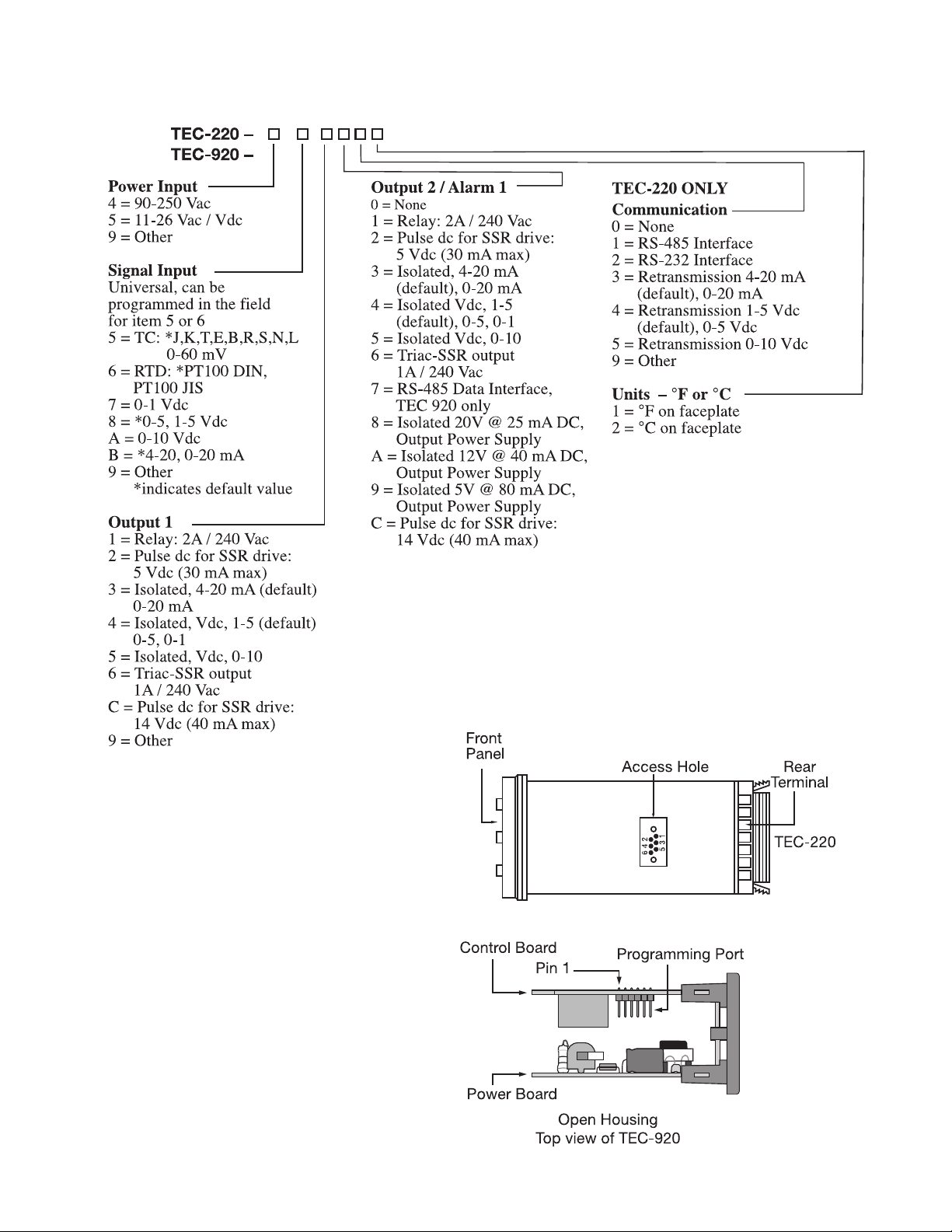
1–2 Ordering Code
1–3 Programming Port
A special connector can be used to
connect the programming port to a PC
for automatic configuration.
The programming port is used for offline automatic setup and testing procedures only. Don't attempt to make any
connection to these pins when the unit
is under power.
Figure 1.2
Programming Port Overview
2
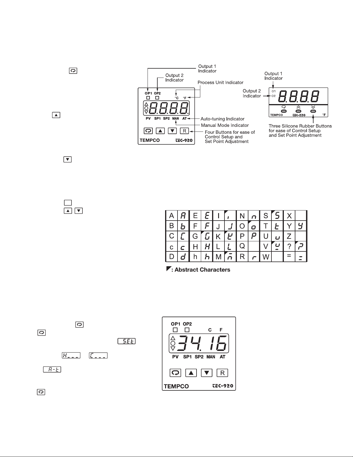
1–4 Keys and Displays
R
KEYPAD OPERATION
SCROLL KEY:
This key is used to select a parameter to be
viewed or adjusted.
UP KEY:
This key is used to increase the value of the
selected parameter.
DOWN KEY:
This key is used to decrease the value of the
selected parameter.
Figure 1.3
Front Panel Description
RESET KEY: for TEC-920,
for TEC-220
This key is used to:
1. Revert the display to show the process value.
2. Reset the latching alarm, once the alarm condition is removed.
3. Stop the manual control mode, auto-tuning
mode, and calibration mode.
4. Clear the message of communication error and
auto-tuning error.
5. Restart the dwell timer when the dwell timer has
timed out.
6. Enter the manual control menu when in failure
mode.
ENTER KEY: Press for 5 seconds or longer.
Press for 5 seconds to:
1. Enter setup menu. The display shows .
2. Enter manual control mode — when manual
control mode or is selected.
3. Enter auto-tuning mode — when auto-tuning
mode (for 220) or AT (for 920) is selected.
4. Perform calibration to a selected parameter during the calibration procedure.
Press for 6.2 seconds to select calibration mode.
Table 1.1 Display Form of Characters
Displays program code of the
instrument for 2.5 seconds.
The diagram at left shows
program no. 34, version 16
for the TEC-920.
The program no. is 33 for the
TEC-220.
Figure 1.4
Display in Initial Stage
3
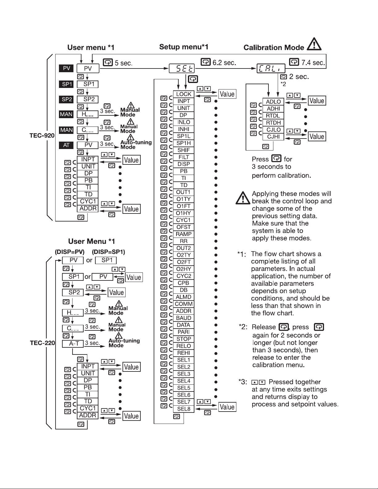
1–5 Menu Overview
4
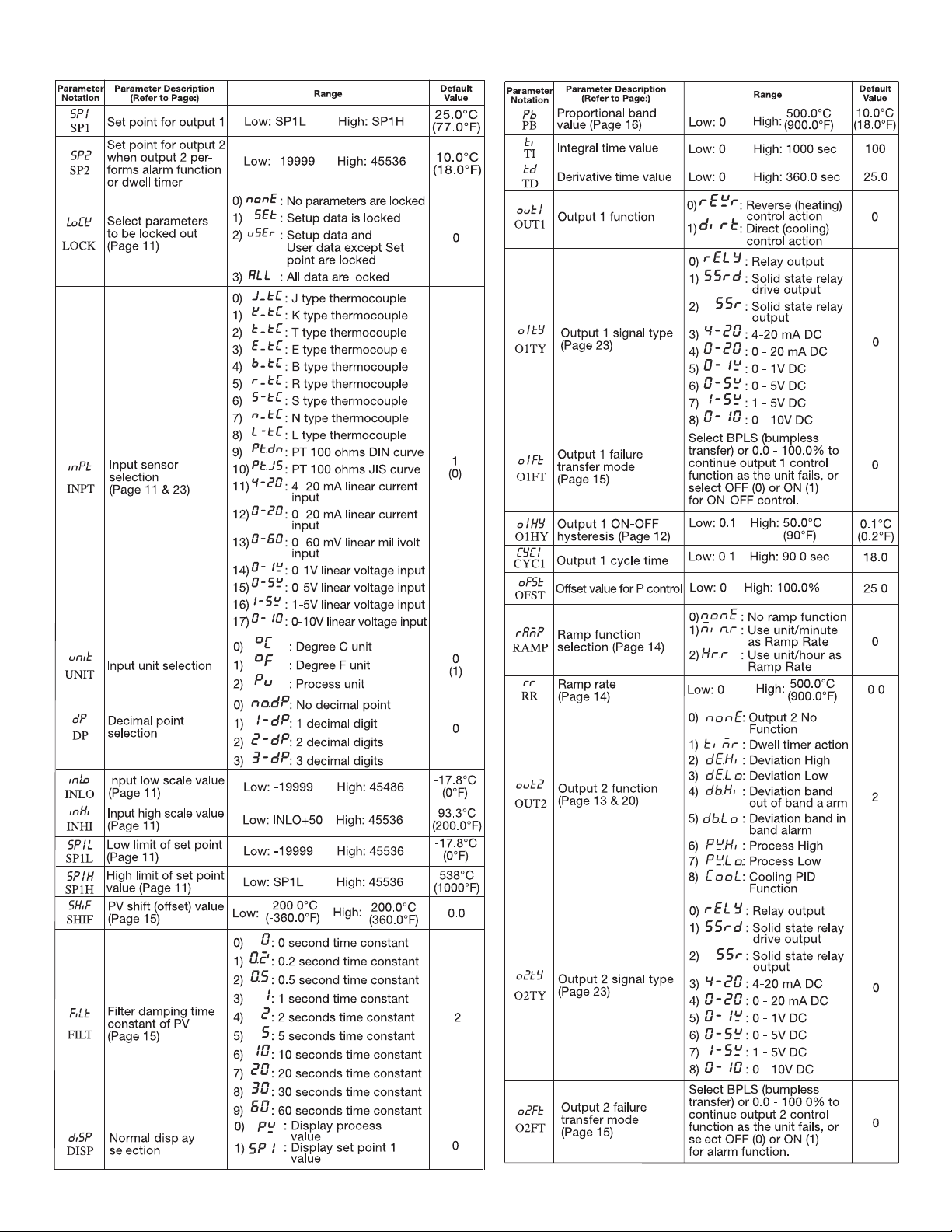
1–6 Parameter Descriptions
5
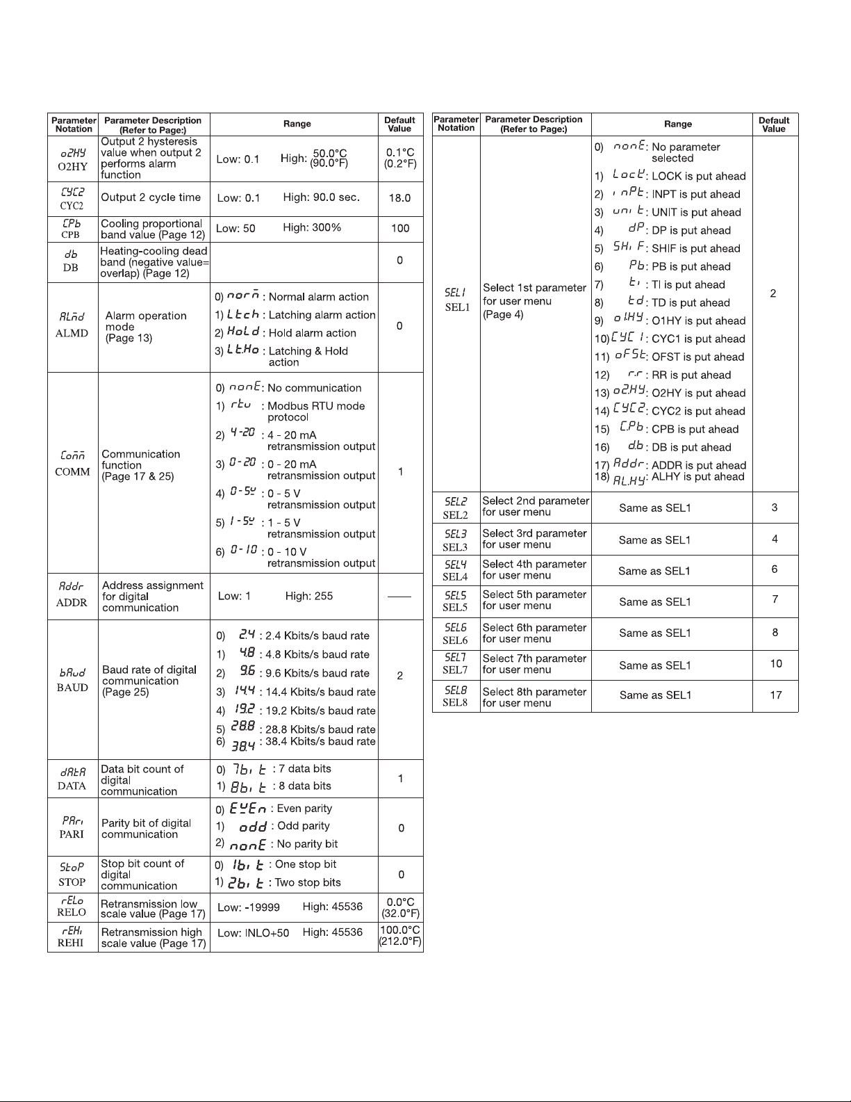
1–6 Parameter Descriptions, continued…
6
Chapter 2 Installation
Dangerous voltages capable of causing death are some-
times present in this instrument. Before installation or
beginning any troubleshooting procedures, the power to all
equipment must be switched off and isolated. Units suspected of
being faulty must be disconnected and removed to a properly
equipped workshop for testing and repair. Component replacement and internal adjustments must be made by a qualified maintenance person only.
This instrument is protected by double insulation. To
minimize the possibility of fire or shock hazards do not
expose this instrument to rain or excessive moisture.
Do not use this instrument in areas under hazardous con-
ditions such as excessive shock, vibration, dirt, moisture,
corrosive gases or oil. The ambient temperature of the area
should not exceed the maximum rating specified in chapter 6.
Remove stains from this instrument using a soft, dry
cloth. To avoid deformation or discoloration do not use
harsh chemicals, volatile solvent such as thinner or strong detergents to clean this instrument.
2–1 Unpacking
Upon receipt of the shipment, remove the unit from the carton
and inspect the unit for shipping damage.
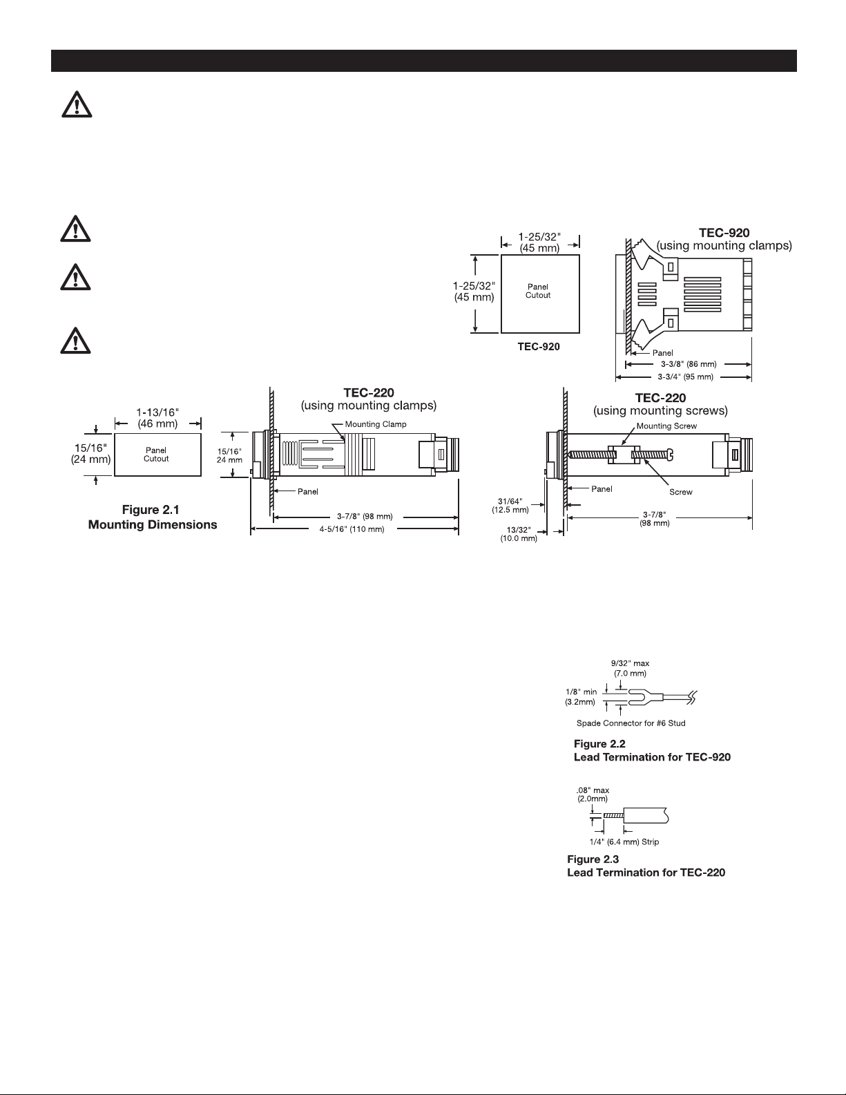
2–2 Mounting
Make the panel cutout according to the dimensions shown in
Figure 2.1.
Take the mounting clamp away and insert the controller into the
panel cutout. Reinstall the mounting clamp.
2–3 Wiring Precautions
• Before wiring, verify the correct model number and options on the label.
Switch off the power while checking.
• Care must be taken to ensure that the maximum voltage rating specified on
the label is not exceeded.
• It is recommended that the power for these units be protected by fuses or circuit breakers rated at the minimum value possible.
• All units should be installed in a suitable enclosure to prevent live parts from
being accessible to human hands and metal tools. Metal enclosures and/or
subpanels should be grounded in accordance with national and local codes.
• All wiring must conform to appropriate standards of good practice and local
codes and regulations. Wiring must be suitable for the voltage, current, and
temperature rating of the system.
• Beware not to over-tighten the terminal screws. The torque should not
exceed 1 N-m (8.9 lb-in or 10 KgF-cm).
• Unused control terminals should not be used as jumper points as they may
be internally connected, causing damage to the unit.
• Verify that the ratings of the output devices and the inputs as specified are
not exceeded.
• Except for thermocouple wiring, all wiring should use stranded copper conductor with a maximum gage of 14 AWG.
• Electrical power in industrial environments contains a certain amount of
noise in the form of transient voltage and spikes. This electrical noise can
adversely affect the operation of microprocessor-based controls. For this
reason the use of shielded thermocouple extension wire which connects the
sensor to the controller is strongly recommended. This wire is a twisted-pair
construction with foil wrap and drain wire. The drain wire is to be attached
to ground in the control panel only.
Note: All model TEC-220 controls are supplied with
both mounting clamps and mounting screws. The
mounting screws have to be used in NEMA 4X applications as they allow the control to be held tighter
into the panel. The mounting clamp teeth are released
by depressing the ends of the clamp together.
Transit Damage
If there is any damage due to transit, report it and
file a claim with the carrier. Write down the model
number, serial number, and date code for future reference when corresponding with our service center.
The serial number (S/N) is labeled on the box and
the housing of the control.
Wiring, continued…
7
 Loading...