

Tempco Photohelic 3005, Photohelic 3003, Photohelic 3008, Photohelic 3006, Photohelic 3002 Installation And Operating Instructions Manual
...
TEMPCO s.a. 4e ave. N°114, Z.I. des Hauts Sarts, B-4040 Herstal, Belgique. T:(32)04-2649458, F:(32)04-2649476, www.tempco.be, tempco@tempco.be
Les photos et caractéristiques présentés dans ce catalogue sont données à titre indicatif et ne sont pas contractuelles.
3.A.01.450-E-100910 page 1/7
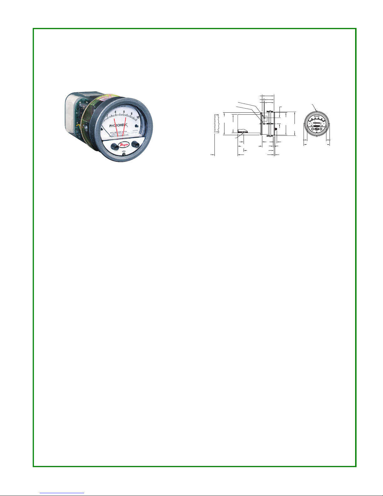
The Photohelic®Switch/Gage is a very versatile, precise
pressure switch combined with the time-proven
Magnehelic®pressure gage. Models are available with one
or two phototransistor actuated relays. Gage reading is
unaffected by switch operation. Easy to adjust set points
have knob controls. Applied pressure and switch set points
are fully visible at all times. Deadband is one pointer width less than 1% of full scale. Double-pole double-throw relays
can be easily interlocked to provide variable deadband control. For positive, negative or differential pressure only on
3600S models. Full scale ranges available from 0-.25 in w.c.
to 0-6000 psig.
PHOTOHELIC®SENSING - HOW IT WORKS
In a typical control application, the Photohelic®switch/gage
controls between high and low pressure set points. When
pressure changes, reaching either set point pressure, the
beam from an LED to the limiting phototransistor will be cut
off by the helix-driven light shield. The resulting signal
change is electronically amplified to actuate its DPDT slave
relay and switching occurs. Dead band between make and
break is 1% of full scale or less - just enough to assure positive, chatter-free operation.
Series 3000 Photohelic®Pressure Switch/Gage
Specifications - Installation and Operating Instructions
SPECIFICATIONS
GAGE SPECIFICATIONS
Service: Air and non-combustible, compatible gases.
Wetted Materials: Consult Factory.
Accuracy: Photohelic®, ±2% of full scale at 70°F (21.1°C). ±3%
on -0 and ±4% on -00 models.
Pressure Limits: Photohelic
®
-20" Hg. to 25 psig (-0.677 to
1.72 bar). MP option; 35 psig (2.41 bar), HP option; 80 psig
(5.52 bar). 36003S – 36010S; 150 psig (10.34 bar). 36020S and
higher; 1.2 x full scale pressure.
Temperature Limits: 20 to 120°F.
(-6.67 to 48.9°C) Low temperature option available.
Process Connections: Photohelic
®
, 1/8˝ female NPT.
Size: Photohelic®, 4˝ (101.6 mm) dial face, 5˝ (127 mm) O.D. x 8-
1/4˝ (209.55 mm).
Weight: Photohelic
®
, 4 lbs. (1.81 kg).
SWITCH SPECIFICATIONS
Switch Type: Each setpoint has 2 Form C relays (DPDT).
Repeatability: ±1% of full scale.
Electrical Rating: Photohelic
®
, 10A @ 28 VDC, 10A @ 120,
240 VAC.
Electrical Connections: Screw Terminals.
Power Requirements: 120 VAC, 50/60 Hz; 240 VAC & 24 VAC
Power optional.
Mounting Orientation: Diaphragm in vertical position. Consult
factory for other position orientations.
Set Point Adjustment: Adjustable knobs on face.
Agency Approvals: Photohelic
®
UL, CSA, CE.
2-1/2 [63.50]
2-1/16 [52.39]
2 [50.80]
1-1/4
[31.75]
(4) 6-32 HOLES
EQUALLY SPACED ON
A 5-1/8 [130.18] B.C.
Ø4-47/64
[120.25]
Ø5
[127.00]
Ø4 [101.60]
FAC E
5-1/2 [139.70]
O.D.
MOUNTING
RING
5/8 [15.88]
5/8 [15.88] PANEL
MAX
3/16 [4.76]
3-7/8 [98.43]
5-1/8 [130.18]
6-3/8 [161.93]
(7-5/8 [193.68])
4-3/8 [111.13]
HOUSING REMOVAL
3/4 CONDUIT
CONNECTION
Ø4-3/4
[120.65]
3-7/8 SQ
[98.43]
1/8 FEMALE NPT HIGH
PRESSURE CONNECTION
1/8 FEMALE NPT LOW
PRESSURE CONNECTION
*Patent No. 3,862,416
6
TEMPCO s.a. 4e ave. N°114, Z.I. des Hauts Sarts, B-4040 Herstal, Belgique. T:(32)04-2649458, F:(32)04-2649476, www.tempco.be, tempco@tempco.be
Les photos et caractéristiques présentés dans ce catalogue sont données à titre indicatif et ne sont pas contractuelles.
3.A.01.450-E-100910 page 2/7
INSTALLATION
1. Location
All parts of the Dwyer Photohelic®pressure switch/gage are
ruggedly constructed and will stand a moderate amount of
vibration, physical shock, and handling. Normal care in handling and installation is all that is required. In cases where
instrument panel vibration is severe, the panel should be a
spring mounted or the amplifier-relay unit mounted remotely on a more stable surface.
Select a location where the ambient temperature will not
exceed 120°F. Pneumatic pressure sensing lines may be run
any necessary distance. For example, 250 foot sensing lines
will not affect accuracy but will damp the reading slightly. Do
not restrict lines. If pulsating pressure or vibration causes
excessive pointer oscillation or relay chatter, consult factory
for additional damping means.
2. Position
The Photohelic®may be mounted as an integral package or
the amplifier-load relay assembly and housing may be
mounted remotely from the indicating gage-phototransistor
unit. Extension cords with 7 pin plugs and receptacles are
available from Dwyer for interconnection of the two units.
The unit may be mounted in any desired position, scale vertical or horizontal, without affecting its accuracy, but must
be rezeroed if position is changed from horizontal to vertical
or vice versa. The -0 and -00 models must be mounted with
the scale vertical.
3. Mounting
The Photohelic
®
is normally mounted before making electrical connections, as the electrical enclosure is independent
of the mounting means and may be removed at any time.
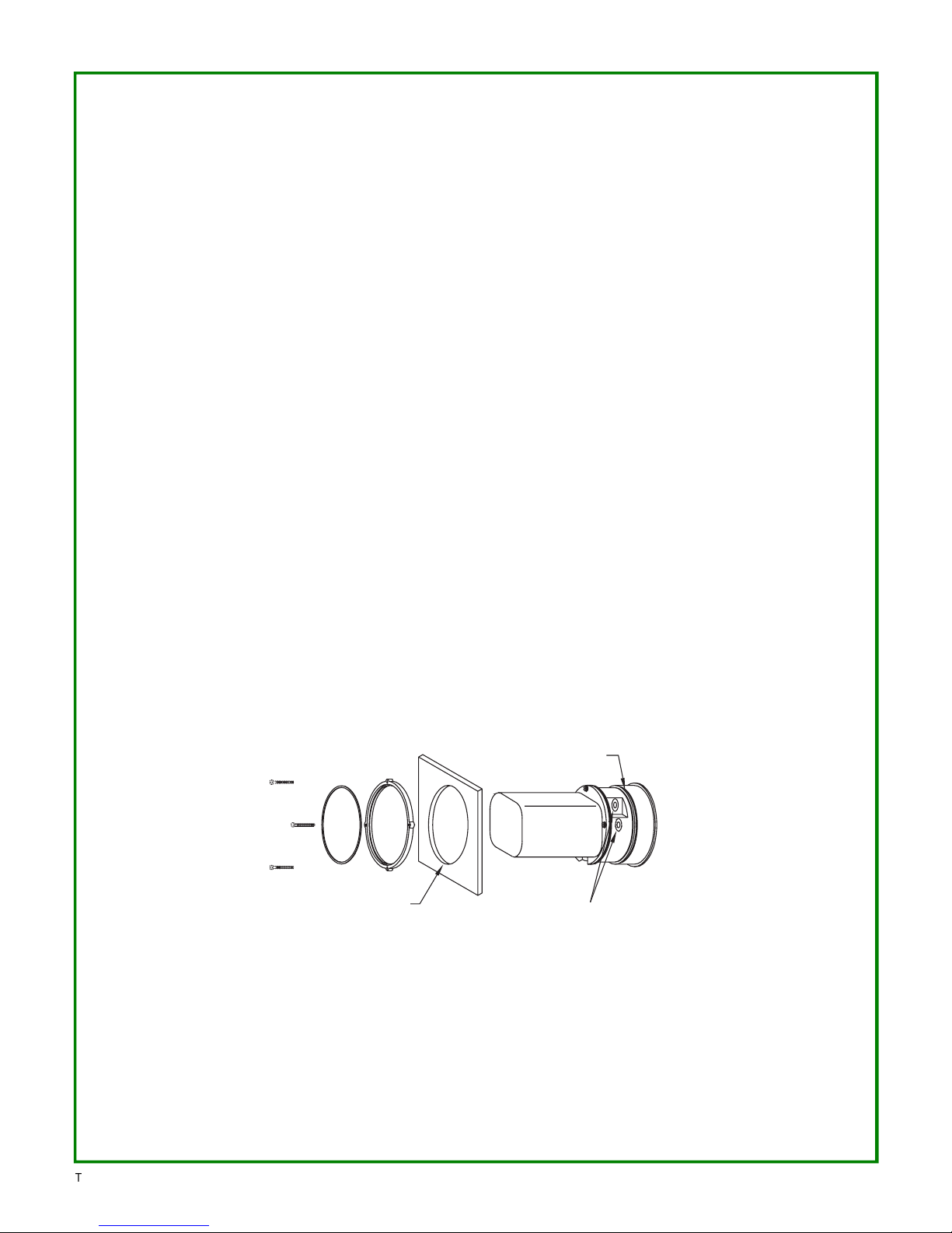
Panel Mounting
Normal mounting is flush or through panel is shown in Fig.
2. Be sure to allow 4-3/8˝ extra space behind the unit for
electrical enclosure removal. Make a single 4-13/16˝ diameter hole in the panel. Insert the entire Photohelic® unit from
the front, then slip on the mounting ring and snap ring from
the rear. Seat the snap ring in its groove, back up the
mounting ring against snap ring and tighten the four (4) 2˝
No. 6-32 clamp screws provided. If behind panel space is
critical, the amplifier-relay unit can be mounted remotely.
See the Remote-Relay Mounting Instructions for details.
Fig. 2
SNAP RING GROOVE
4-13/16˝ (122 mm)
DIA. HOLE REQUIRED
FOR PANEL MOUNTING
1/8˝ MALE NPT PRESSURE CONNECTIONS.
SINGLE HIGH PRESSURE CONNECTION
FOR SERIES 36000A MODELS.
Through Panel Mounting
6
TEMPCO s.a. 4e ave. N°114, Z.I. des Hauts Sarts, B-4040 Herstal, Belgique. T:(32)04-2649458, F:(32)04-2649476, www.tempco.be, tempco@tempco.be
Les photos et caractéristiques présentés dans ce catalogue sont données à titre indicatif et ne sont pas contractuelles.
3.A.01.450-E-100910 page 3/7
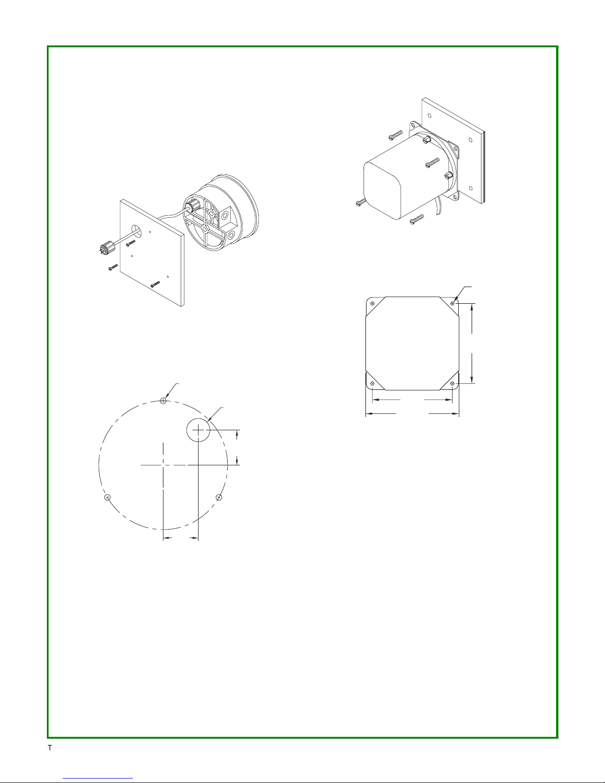
Gage Mounting with Relays Remote
Where it is desirable to mount the amplifier-relay unit separate from the gage-phototransistor unit, the gage may be
mounted either as shown in Fig. 2 (except less amplifierrelay portion) or surface mounted as shown in Fig. 3A. Use
the layout shown in Fig. 3B to locate holes. The complete
package cannot be surface mounted.
Remote Relays Mounting
The amplifier - relay unit may be mounted remotely as
shown in Fig. 4A. Use the hole layout as shown in Fig. 4B
for this option.
Additional mounting information for special requirements is
available from the factory.
4. Pneumatic Connections & Zeroing
After installation but before making pressure connections,
set the indicating pointer exactly on the zero mark, using the
zero adjust screw located at the bottom of the front cover.
Note that this adjustment can only be made with the high
and low pressure taps both open to atmosphere.
Connect the high and low pressure taps to positive, negative, or differential pressure sensing points. Use 1/4˝ diameter metal or other instrument tubing and 1/8˝ NPT adaptors
at the Dwyer Photohelic®pressure switch gage. Adaptors
for rubber or soft plastic tubing are furnished with the instrument for use where this type of connection is preferred.
If the Photohelic®is not used to sense differential pressure,
one of the pressure taps must be left open to atmosphere.
This will allow the reference pressure to enter. In this case,
installation of a Dwyer No. A-331 Filter Plug or similar fitting
in the reference pressure tap is recommended to reduce the
possibility of dust entering the instrument.
NOTE: If the Photohelic®switch/gage is over pressured,
pointer may ‘jump” from full scale back to zero and remain
there until the excess pressure condition is relieved. Users
should be aware of possible false zero pressure indications
under this conditions.
Fig. 3A
Remote Amplifier-Relay Unit
4-9/32
[108.74]
5
[127.00] SQ
4-9/32
[108.74]
Ø3/16
TYP 4 PLACES
Surface Mounting
Fig. 3B
Hole Layout (Front)
1-1/8
[28.58]
1-1/8
[28.58]
THREE 3/16 DIA.
HOLES AT 120°
SURFACE MTG.
3/4 DIA. HOLE
FOR WIRE CONN.
Fig. 4A
Hole Layout
Fig. 4B
 Loading...