

Page 1
Page 1 of 16
Visionary Solutions for Industry®Since 1972 — ISO 9001 Certified
®
®
Temperature Contro llers & Sen sors ◆ Heating E lements ◆ Proc ess Heating Systems
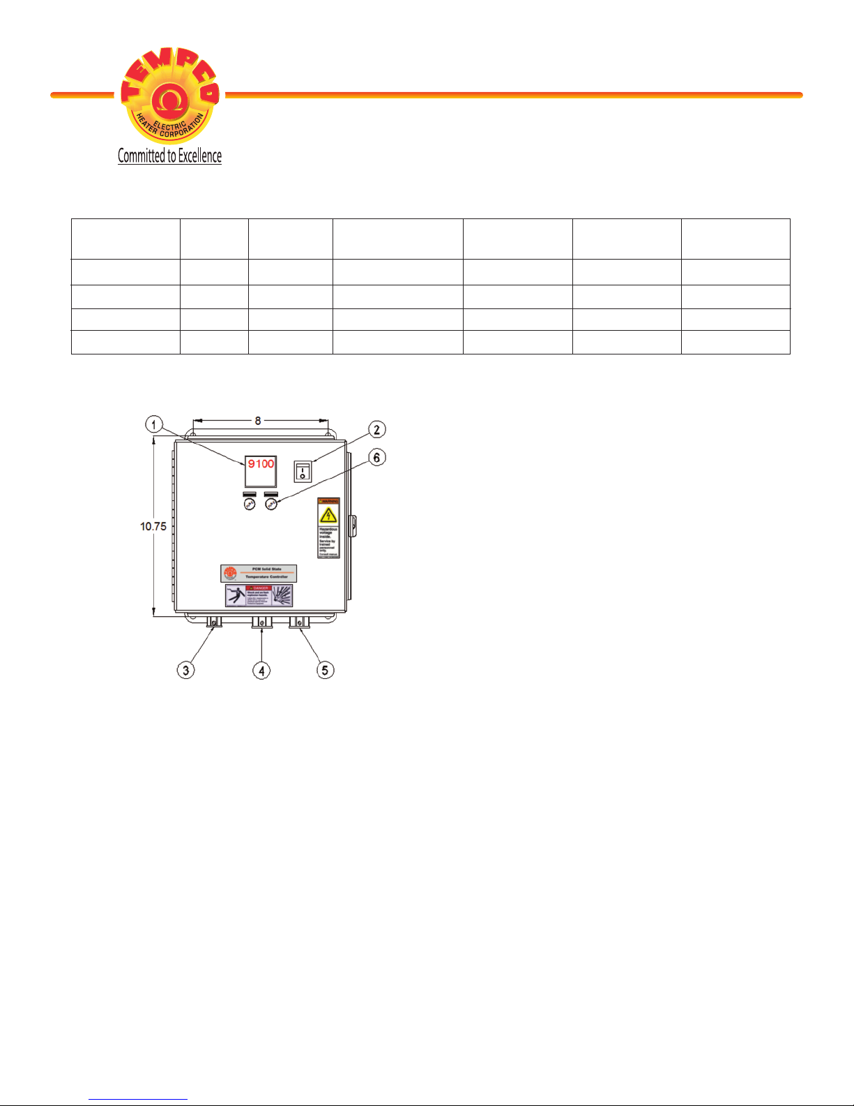
Instructions for Tempco PCM10005 through PCM10008 Enclosure
Part Number Input Max. Required Heater Max. Wattage Max. Wattage Mounting
voltage Amperage Fusing 1ph 3ph Dimensions
PCM10005 240VAC 24 30amps 5760 9970W 10.75H x 8W
PCM10006 480VAC 24 30amps 11,520 19,930W 14.75H x 8W
PCM10007 240VAC 48 60amps 11,520 19,930W 14.75H x 8W
PCM10008 480VAC 48 60amps 23,000 39,900W 14.75H x 8W
Component Identification
(Dimensions shown (inches) are for PCM10005 only)
1: TEC-9100 Controller
2: On-Off Rocker Switch
3: 1/2" EMT Conn. For Sensor
4: 3/4" EMT Conn. For Heater Power
5: 3/4" EMT Conn. For Incoming Power
6: 2 Fuse Holders, see spare parts for
fuse replacement
There is no disconnect or heater fusing in this enclosure.
Heater fusing and disconnect must be supplied by the installer.
It is strongly recommended that the process should incorporate a LIMIT CONTROL such
as the TEC-910 which will shut down the equipment at a preset process condition in order
to preclude possible damage to products or system.
1. Dangerous voltage capable of causing injury or death is present within this enclosure. Power
to all equipment must be disconnected before installation or beginning any troubleshooting
procedures. All wiring and component replacement must be made by qualified personnel only.
2. To minimize the possibility of fire or shock, do not expose this console to rain or excessive
moisture.
3. Do not use this enclosure in areas where hazardous conditions exist such as excessive shock,
vibration, dirt, corrosive gases, oil or where explosive gases or vapors are present.
© 2015 Tempco Electric Heater Corporation (Revision 7/8/2015)
607 N. Central Avenue
TEMPCO Electric Heater Corporation
◆ Wood Dale, IL 60191-1452 USA ◆ 630.350.2252 ◆ Fax: 630.350.0232
E-mail: info@tempco.com
◆ Web: www.tempco.com
Page 1 of 16
Page 2

Page 2 of 16
WIRING (for safety, disconnect all power sources prior to wiring)
. Attach the leads from your sensor to the sensor terminal block, terminals 7, 8 & 9. For a ther-
1
mocouple, most commonly the red lead is negative (-) negative, attach that to terminal 9. The
positive lead of the thermocouple should be connected to terminal 8.
The TEC-9100 controller is preprogrammed to accept a type J thermocouple. If another sensor
is used, the “INPT” setting has to be revised.
2. Make sure your service power has been disconnected and locked out.
Please note the enclosed wiring diagram.
Wire your single phase supply to terminals 1 & 2. If you are using three phase power, wire to
terminals 1, 2 & 3.
Connect your heater load to terminals 4 & 5 if using single phase, 4, 5 & 6 if using three phase.
Follow all local and national codes.
Add disconnect and fusing as required.
Before applying power, check tightness of all terminals.
3. An optional NO-NC alarm can be connected to terminals 1, 2 & 3 of the TEC-9100 controller.
This relay is rated at 2 amps, 240 volts. See Alarm Wiring Diagrams on page 6.
OPERATION
1. Refer to the instruction manual provided for complete operation and auto-tuning instructions
for the TEC-9100 temperature controller.
2. Close and secure the door. Switch on the enclosure. Using the up & down pushbuttons on the
TEC-9100 controller, start out with the temperature set low to test your system performance.
If the set point temperature is being maintained, set your desired temperature setpoint.
If your setpoint temperature is not being maintained, please refer to the auto-tuning procedure
in the attached manual.
If auto-tuning does not produce the required results, manual tuning may be necessary.
Note: The signal of the output circuit is wired through output 2 of the TEC-9100 which can
be used as a cut-out in the event of an over-setpoint temperature condition. This is
a deviation contact set to 30º F above the setpoint.
In the event of an over-setpoint temperature condition, output 2 will open, cutting
the control signal to the output relay.
This deviation setpoint can be changed by accessing “SP2” in the TEC-9100 (note
following). This is not meant to be a redundant safety controller.
Refer to our TEC-910 for a safety controller.
SPARE/REPLACEMENT PARTS
Part Number Description
EHD-124-137 (2) TEC Control fuses rated 1 amp, 250VAC, 1/4" x 1-1/4",
Bussmann AGC-1 or equal (PCM10005/PCM10007)
EHD-124-253 (2) TEC Control fuses rated 3/10 amp, 600VAC class CC.
Littelfuse KLDR-3/10 or equal (PCM10006/PCM10008)
TEC14217 (1) Temperature Control, TEC-9100
Page 2 of 16
Page 3
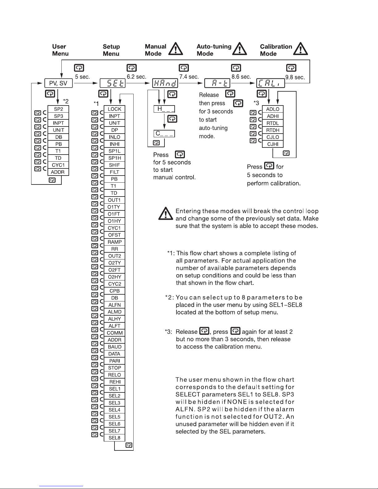
1–5 Menu Overview
Page 3 of 16
Page 4
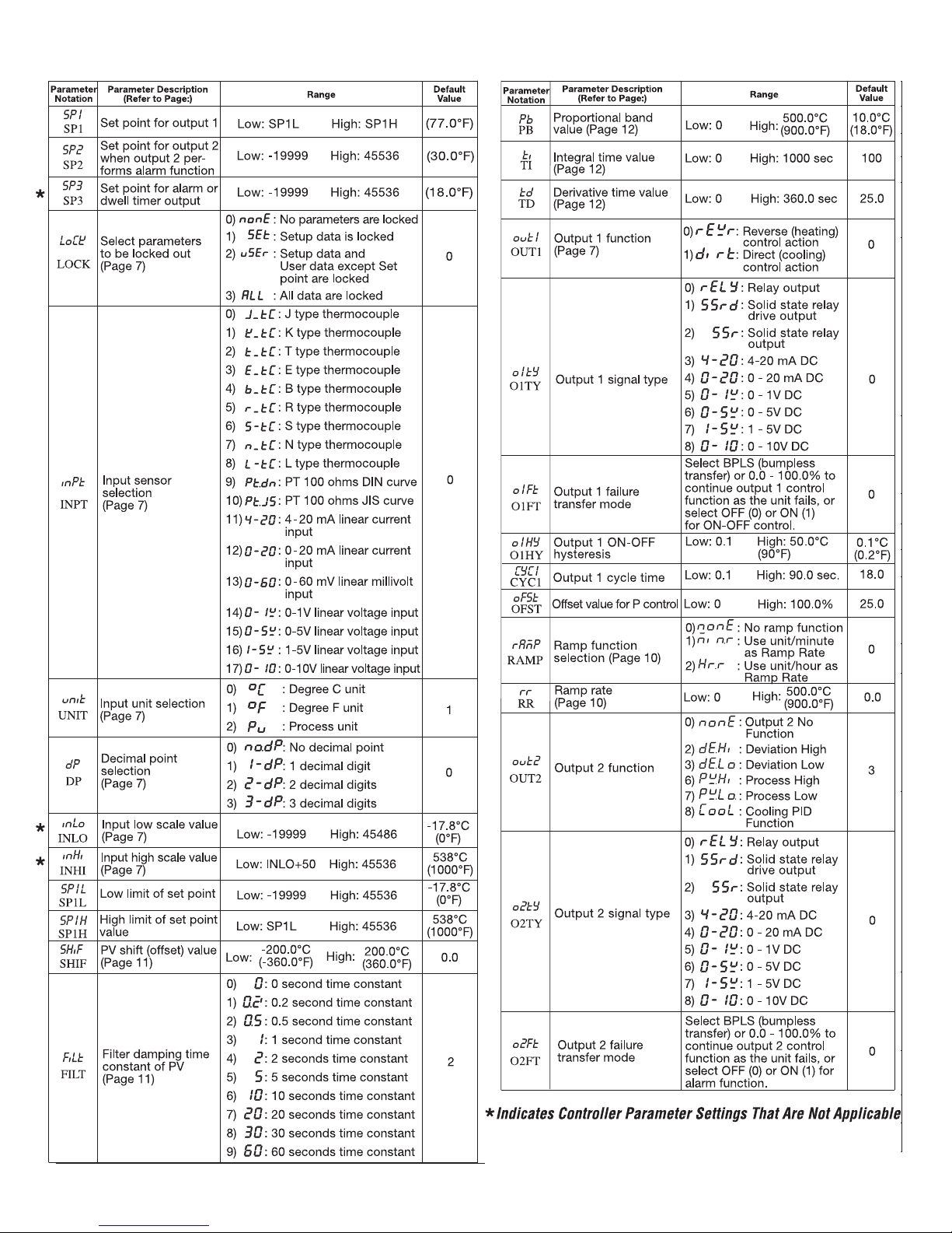
1–6 Parameter Descriptions (page 1 of 2)
❋ Indicates Controller Parameter Settings that are not applicable.
Page 4 of 16
Page 5
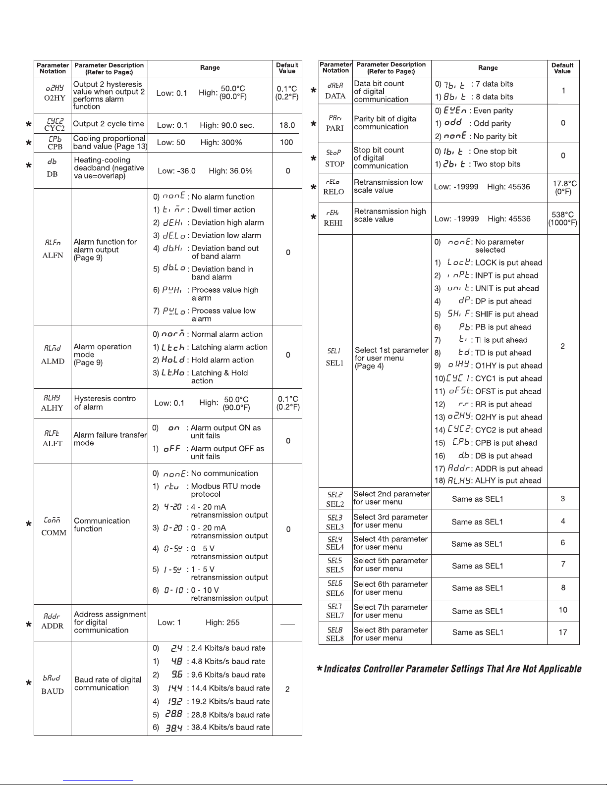
Parameter Descriptions (page 2 of 2)
Page 5 of 16
Page 6

Alarm Wiring
Page 6 of 16
Page 7

Chapter 3 Programming
Press for 5 seconds and release to enter the setup menu. Press
o select the desired parameter. The upper display
t
indicates the parameter symbol, and the lower display indicates
the selected value of the parameter.
3–1 Lockout
There are four security levels that can be selected using the LOCK
parameter.
If NONE is selected for LOCK, then no parameter is locked.
If SET is selected for LOCK, then all setup data are locked.
If USER is selected for LOCK, then all setup data as well as
user data (refer to section 1-5) except the set point are
locked to prevent them from being changed.
If ALL is selected for LOCK, then all parameters are locked to
prevent them from being changed.
3–2 Signal Input
NPT: Selects the sensor type or signal type for signal input.
I
Range: (thermocouple) J-TC, K-TC, T-TC, E-TC, B-TC,
-TC, S-TC, N-TC, L-TC
R
(RTD) PT.DN, PT.JS
UNIT: Selects the process unit
Range: °C, °F
DP: Selects the resolution of process value.
Range: (For T/C and RTD) NO.DP, 1-DP
3–3 Control Outputs
There are four kinds of control modes that can be configured as shown in table 3.1.
Table 3.1 Heat-Cool Control Setup Value
Page 7 of 16
Page 8

Control Outputs, continued…
Heat only ON-OFF control: Select REVR for OUT1. Set PB
proportional band) to 0. O1HY is used to adjust dead band for
(
ON-OFF control. The output 1 hysteresis (O1HY) is enabled
in case PB=0. The heat only on-off control function is shown
in the following diagram:
ool only control: ON-OFF control, P (PD) control, and PID
C
control can be used for cool control. Set OUT1 to DIRT (direct
action). The other functions for cool only ON-OFF control, cool
only P (PD) control, and cool only PID control are the same as
for heat only control except that the output variable (and action)
or cool control is inverse to heat control.
f
NOTE: ON-OFF control may result in excessive overshoot and
ndershoot problems in the process. P (or PD) control will result
u
in a deviation of process value from the set point. It is recommended to use PID control for heat-cool control to produce a stable
and zero offset process value.
Other setup required: O1TY, CYC1, O2TY, CYC2, O1FT and
O2FT are set in accordance with the types of OUT1 and OUT2
installed. CYC1 and CYC2 are selected according to the output
1 type (O1TY) and output 2 type (O2TY). Generally, select
0.5~2 seconds for CYC1 if SSRD or SSR is used for O1TY;
10~20 seconds if relay is used for O1TY. CYC1 is ignored if a
linear output is used. Similar conditions are applied for CYC2
selection.
You can use the auto-tuning program for the new process or directly set the appropriate values for PB, TI, and TD according
to historical records for the repeated systems. If the control behavior is still inadequate, use manual tuning to improve the control. See section 3-12 for manual tuning.
The ON-OFF control may introduce excessive process oscillation
even if hysteresis is minimized. If ON-OFF control is set (i.e.,
PB=0), TI, TD, CYC1, OFST, CYC2, CPB, and DB will be hidden
and have no function in the system. The auto-tuning and bumpless
transfer functions will be disabled as well.
Heat only P (or PD) control: Select REVR for OUT1, set TI to
0. OFST is used to adjust the control offset (manual reset). O1HY
is hidden if PB is not equal to 0. OFST function: OFST is meas-
ured by % with a range of 0–100.0%. In the steady state (i.e.,
process has been stabilized), if the process value is lower than the
set point by a definite value, say 5°C, while 20°C is used for PB,
that is lower by 25%, then increase OFST 25%, and vice-versa.
After adjusting OFST value, the process value will be varied and
eventually coincide with set point.
Refer to section 3-12 “manual tuning” for the adjustment of PB
and TD. Manual reset (adjust OFST) is not practical because the
load may change from time to time and OFST may need to be adjusted repeatedly. PID control can avoid this situation.
Heat only PID control: If REVR is selected for OUT1, PB and
TI should not be zero. Perform auto-tuning for the new process,
or set PB, TI, and TD with historical values. See section 3-11 for
auto-tuning operation. If the control result is still unsatisfactory,
then use manual tuning to improve control. See section 3-12 for
manual tuning. The unit contains a very advanced PID and Fuzzy
Logic algorithm to create a very small overshoot and very quick
response to the process if it is properly tuned.
3.3 & 3.4 Alarm Figures, next page…
Page 8 of 16
Page 9

3.3 & 3.4 Alarm Figures
Figure 3.3 Output 2 Deviation High Alarm
3–4 Alarm
The controller has one alarm output. There are six types of
alarm functions and one dwell timer that can be selected, and
our kinds of alarm modes (ALMD) are available for each
f
alarm function (ALFN). Output 2 can be configured as another alarm in addition to the alarm output. But output 2 only
provides four kinds of alarm functions and only normal alarm
mode is available for this alarm. When output 2 is used as an
alarm, SP2 sets the trigger point. SP3 sets the trigger point for
Alarm.
A process alarm sets absolute trigger levels. When the
process is higher than SP3, a process high alarm (PV.HI) occurs, and the alarm is off when the process is lower than SP3ALHY. When the process is lower than SP3, a process low
alarm (PV.LO) occurs, and the alarm is off when the process
is higher than SP3+ALHY. A process alarm is independent of
the set point.
A deviation alarm alerts the user when the process deviates
from the set point. When the process is higher than SV+SP3,
a deviation high alarm (DE.HI) occurs, and the alarm is off
when the process is lower than SV+SP3-ALHY. When the
process is lower than SV+SP3, a deviation low alarm
(DE.LO) occurs, and the alarm is off when the process is
higher than SV+SP3+ALHY. The trigger level of the deviation alarm moves with the set point.
A deviation band alarm presets two trigger levels relative to
the set point. The two trigger levels are SV+SP3 and SV-SP3
for alarm. When the process is higher than (SV+SP3) or lower
than (SV-SP3), a deviation band high alarm (DB.HI) occurs.
When the process is within the trigger levels, a deviation band
low alarm (DB.LO) occurs.
There are four types of alarm modes available for each alarm
function. These are: normal alarm, latching alarm, holding
alarm and latching/holding alarm. They are described as follows:
Figure 3.4 Output 2 Process Low Alarm
Normal alarm: ALMD=NORM
When a normal alarm is selected, the alarm output is de-energized in the non-alarm condition and energized in an alarm
condition.
Latching alarm: ALMD=LTCH
If a latching alarm is selected, once the alarm output is energized, it will remain unchanged even if the alarm condition is
cleared. The latching alarm is reset when the RESET key is
pressed after the alarm condition is removed.
Holding alarm: ALMD=HOLD
A holding alarm prevents an alarm when the control is powering up. The alarm is enabled only when the process reaches
the set point value. Afterwards, the alarm performs the same
function as a normal alarm.
Latching/holding alarm: ALMD=LT.HO
A latching/holding alarm performs both holding and latching
functions. The latching alarm is reset when the RESET key is
pressed after the alarm condition is removed.
Alarm failure transfer is activated as the unit enters failure
mode. The alarm will go on if ALFT is set for ON and go off
if ALFT is set for OFF. The unit will enter failure mode when
a sensor break occurs or if the A-D converter of the unit fails.
Page 9 of 16
Page 10

3–5 Configuring User Menu
Most conventional controllers are designed with a fixed order in
which the parameters scroll. The x100 series have the flexibility
o allow you to select those parameters which are most significant
t
to you and put these parameters at the front of the display sequence.
SEL1~SEL8: Selects the parameter for view and change in the
user menu.
Range: LOCK, INPT, UNIT, DP, SHIF, PB, TI, TD, O1HY,
CYC1, OFST, RR, O2HY, CYC2, CPB, DB, ADDR, ALHY
When using the up and down keys to select the parameters, you
may not see all of the above parameters. The number of visible parameters is dependent on the setup condition. The hidden parameters for the specific application are also blocked from the SEL
selection.
Example:
OUT2 set for DE.LO PB= 100.0 SEL1 set for INPT
SEL2 set for UNIT SEL3 set for PB SEL4 set for TI
SEL5~SEL8 set for NONE
Now, the upper display scrolling becomes:
3–6 Ramp
Ramp
The ramping function is performed during power up as well as any
time the set point is changed. If MINR or HRR is chosen for
RAMP, the unit will perform the ramping function. The ramp rate
is programmed by adjusting RR. The ramping function is disabled
as soon as failure mode, manual control mode, auto-tuning mode
or calibration mode is entered.
Example without dwell timer
Select MINR for RAMP, select °C for UNIT, select 1-DP for DP,
set RR=10.0. SV is set to 200°C initially, and changed to 100°C
30 minutes after power-up. The starting temperature is 30°C. After
power-up, the process runs like the curve shown below:
3–7 Dwell Timer
The alarm output can be configured as a dwell timer by selecting
TIMR for ALFN (alarm function). As the dwell timer is config-
red, the parameter SP3 is used for dwell time adjustment. The
u
dwell time is measured in minutes ranging from 0.1 to 4553 minutes. Once the process reaches the set point the dwell timer starts
to count down to zero (time out). The timer relay will remain unchanged until time out. For the dwell timer to control the heater,
the heater circuit (or contactor) must be wired in series with the
alarm relay. Note the following diagram located below and also
Figure 2.20.1 on page 11. When the dwell timer times out, the
heater will be turned off. The dwell timer operation is shown in
the following diagram.
After time out, the dwell timer can be restarted by pressing the
RESET key.
The timer stops counting during manual control mode, failure
mode, the calibration period and the auto-tuning period.
If the alarm is configured as a dwell timer, ALHY and ALMD are
hidden.
Figure 3.5 RAMP Function
Note: When the ramp function is used, the lower display will show
the current ramping value. The ramping value is an artificially determined setpoint created and updated by the control to match the
ramp rate set by the user. However, it will revert to show the set
point value as soon as the up or down key is touched for adjustment. The ramping value is initiated to process value either on
power-up or when RR and/or the set point are changed. Setting
RR to zero means no ramp function.
Figure 3.6 Dwell Timer Function
Dwell Timer Function Wiring Diagram
Page 10 of 16
Page 11

3–8 PV Shift
n certain applications it is desirable to shift the con-
I
troller display value (PV) from its actual value. This
can easily be accomplished by using the PV shift
function.
The SHIF function will alter PV only.
Example: A process is equipped with a heater, a sensor, and a subject to be warmed up. Due to the design
and position of the components in the system, the
sensor could not be placed any closer to the part.
Thermal gradient (differing temperatures) is common and necessary to an extent in any thermal system for heat to be transferred from one point to
another. If the difference between the sensor and the
subject is 35°C, and the desired temperature at the
subject to be heated is 200°C, the temperature at the
sensor should be 235°C. You should enter -35°C to
subtract 35°C from the actual process display. This
in turn will cause the controller to energize the load
and bring the process display up to the set point
value.
3–9 Digital Filter
In certain applications, the process value is too unstable to be
read due possibly to electrical noise. A programmable low-pass
filter incorporated in the controller is used to improve this. It
is a first-order filter with the time constant specified by the
FILT parameter. The default value of FILT is set at 0.5 seconds
before shipping. Adjust FILT to change the time constant from
0 to 60 seconds. 0 seconds means no filter is applied to the
input signal. The filter is characterized by the following diagram:
Note
The filter is available only for PV, and is performed for the displayed value only. The controller is designed to use unfiltered
signal for control even if the filter is applied. A lagged (filtered)
signal, if used for control, may produce an unstable process.
Figure 3.7 PV Shift Application
Figure 3.8 Filter Characteristics
3–10 Failure Transfer
The controller will enter failure mode if one
of the following conditions occurs:
1. SBER occurs due to input sensor break
or input current below 1mA if 4–20 mA
is selected or input voltage below 0.25V
if 1–5V is selected.
2. ADER occurs due to the A-D converter
of the controller failing.
Output 1 and output 2 will perform the failure transfer function as the controller enters
failure mode.
Output 1 failure transfer, if activated, will
perform:
1. If output 1 is configured as proportional
control (PB≠ 0), and BPLS is selected
for O1FT, then output 1 will perform
bumpless transfer. Thereafter, the previ-
ous averaging value of MV1 will be
used for controlling output 1.
2. If output 1 is configured as proportional
control (PB≠ 0), and a value of 0 to
100.0% is set for O1FT, then output 1
will perform failure transfer. Thereafter,
the value of O1FT will be used for controlling output 1.
3. If output 1 is configured as ON-OFF
control (PB=0), then output 1 will be
driven OFF if OFF is set for O1FT and
will be driven ON if ON is set for O1FT.
Output 2 failure transfer, if activated, will
perform:
1. If OUT2 is configured as COOL, and
BPLS is selected for O1FT, then output
2 will perform bumpless transfer. There-
after, the previous averaging value of
MV2 will be used for controlling output
2.
2. If OUT2 is configured as COOL, and a
value of 0 to 100.0% is set for O2FT,
then output 2 will perform failure transfer. Thereafter, the value of O1FT will
be used for controlling output 2.
3. If OUT2 is configured as alarm function,
and O2FT is set to OFF, then output 2
will go off. Otherwise, output 2 will go
on if O2FT is set to ON.
Alarm failure transfer is activated as the
controller enters failure mode. Thereafter,
the alarm will transfer to the ON or OFF
state preset by ALFT.
Page 11 of 16
Page 12

3–11 Auto-tuning
The auto-tuning process is performed near the set point.
The process will oscillate around the set point during
he tuning process. Set the set point at a lower value if over-
t
shooting beyond the normal process value is likely to cause
damage.
Auto-tuning is applied in cases of:
Initial setup for a new process
•
• The set point is changed substantially from the previous
auto-tuning value
• The control result is unsatisfactory
Operation:
1. The system has been installed normally.
2. Set the correct values for the setup menu of the unit, but
don’t set a zero value for PB and TI, or the auto-tuning program will be disabled. The LOCK parameter should be set
at NONE.
3. Set the set point to a normal operating value, or a lower value
if overshooting beyond the normal process value is likely to
cause damage.
4. Press and hold until appears on the display.
5. Then press
will begin to flash and the auto-tuning procedure begins.
NOTE: The ramping function, if used, will be disabled when
auto-tuning is taking place.
Auto-tuning mode is disabled as soon as either failure mode or
manual control mode is entered.
Procedures:
Auto-tuning can be applied either as the process is warming
up (cold start), or when the process has been in a steady state
(warm start). After the auto-tuning procedures are completed,
the AT indicator will cease to flash and the unit will revert to
PID control using its new PID values. The PID values obtained are stored in the nonvolatile memory.
Auto-Tuning Error
If auto-tuning fails an ATER message will appear on the upper
display in the following cases:
• If PB exceeds 9000 (9000 PU, 900.0°F or 500.0°C),
• if TI exceeds 1000 seconds,
• if the set point is changed during the auto-tuning procedure.
Solutions to
1. Try auto-tuning once again.
2. Don’t change the set point value during the auto-tuning pro-
cedure.
3. Don’t set a zero value for PB and TI.
4. Use manual tuning instead of auto-tuning (see section 3-12).
5. Touch RESET key to reset message.
again
for at least 5 seconds. The AT indicator
3–12 Manual Tuning
In certain applications auto-tuning may be inadequate for the
control requirements. You can try manual tuning for these applications.
If the control performance using auto-tuning is still unsatisfactory, the following rules can be applied for further adjustment of PID values:
Figure 3.9 Effects of PID Adjustment
Figure 3.9 shows the effects of PID
adjustment on process response.
Page 12 of 16
Page 13

3–13 Manual Control
R
peration
O
To enable manual control, the LOCK parameter should be set
o NONE, then press for 6.2 seconds;
t
(hand control) will appear on the display. Press for 5 seconds, then the MAN indicator will begin to flash and the lower
display will show . The controller is now in manual
control mode. indicates output control variable for out-
ut 1, and indicates control variable for output 2. Now
p
you can use the up and down keys to adjust the percentage
values for the heating or cooling output.
The controller performs open loop control as long as it stays
in manual control mode.
Exit Manual Control
Pressing the key will cause the controller to revert to its
normal display mode.
Page 13 of 16
Page 14

Table A.1 Error Codes and Corrective Actions
Page 14 of 16
Page 15

WARRANTY
Tempco Electric Heater Corporation is pleased to offer sugges-
ions on the use of its products. However, Tempco makes no war-
t
ranties or representations of any sort regarding the fitness for use,
or the application of its products by the Purchaser. The selection,
application, or use of Tempco products is the Purchaser's responsibility. No claims will be allowed for any damages or losses,
hether direct, indirect, incidental, special, or consequential.
w
Specifications are subject to change without notice. In addition,
Tempco reserves the right to make changes–without notification
to the Purchaser–to materials or processing that do not affect compliance with any applicable specification. TEC Temperature Controllers are warranted to be free from defects in material and
workmanship for two (2) years after delivery to the first purchaser
for use. Tempco's sole responsibility under this warranty, at Tempco's option, is limited to replacement or repair, free of charge, or
refund of purchase price within the warranty period specified.
This warranty does not apply to damage resulting from transportation, alteration, misuse, or abuse.
RETURNS
No product returns can be accepted without a completed Return
aterial Authorization (RMA) form.
M
TECHNICAL SUPPORT
Technical questions and troubleshooting help is available from
Tempco. When calling or writing please give as much background
information on the application or process as possible.
E-mail: techsupport@tempco.com
Phone: 630-350-2252
800-323-6859
Page 15 of 16
Page 16

Complete Your Thermal Loop System
With Over 100,000 Various Items
Available from Stock
• Electric Heating Elements
• Thermocouples and RTD Assemblies
• SCR Power Controls
• Solid State Relays
• Mechanical Relays
• Videographic Data Recorders
• Temperature Measurement
• Current Indicators
• Thermocouple and Power Lead Wire
• Wiring Accessories
The Electric Heating Element, Temperature Controls and
Temperature Sensors Handbook
REQUEST YOUR FREE 960 PAGE COPY TODAY!
Call (800-323-6859) or E-mail (info@tempco.com)
Specify Print Edition, CD-ROM or Both
Serving Industry Since 1972
Experience the Advantages of our Diverse and Innovative Products
TEMPCO Electric Heater Corporation
607 N. Central Avenue • Wood Dale, IL 60191-1452 USA
Tel: 630-350-2252 • Toll Free: 800-323-6859
Fax: 630-350-0232 • E-mail: info@tempco.com
Web: www.tempco.com
© Copyright 2015. All Rights Reserved.
Page 16 of 16
 Loading...