

Tempco PCM10001, PCM10002, PCM10003, PCM10004 Instructions Manual
Visionary Solutions for Industry®Since 1972 — ISO 9001 Certified
4.00"
6.75"
1
4
5
2
3
7
6
20A-FAST
1
A-FAST
®
®
Temperature Contro llers & Sen sors ◆ Heating E lements ◆ Proc ess Heating Systems
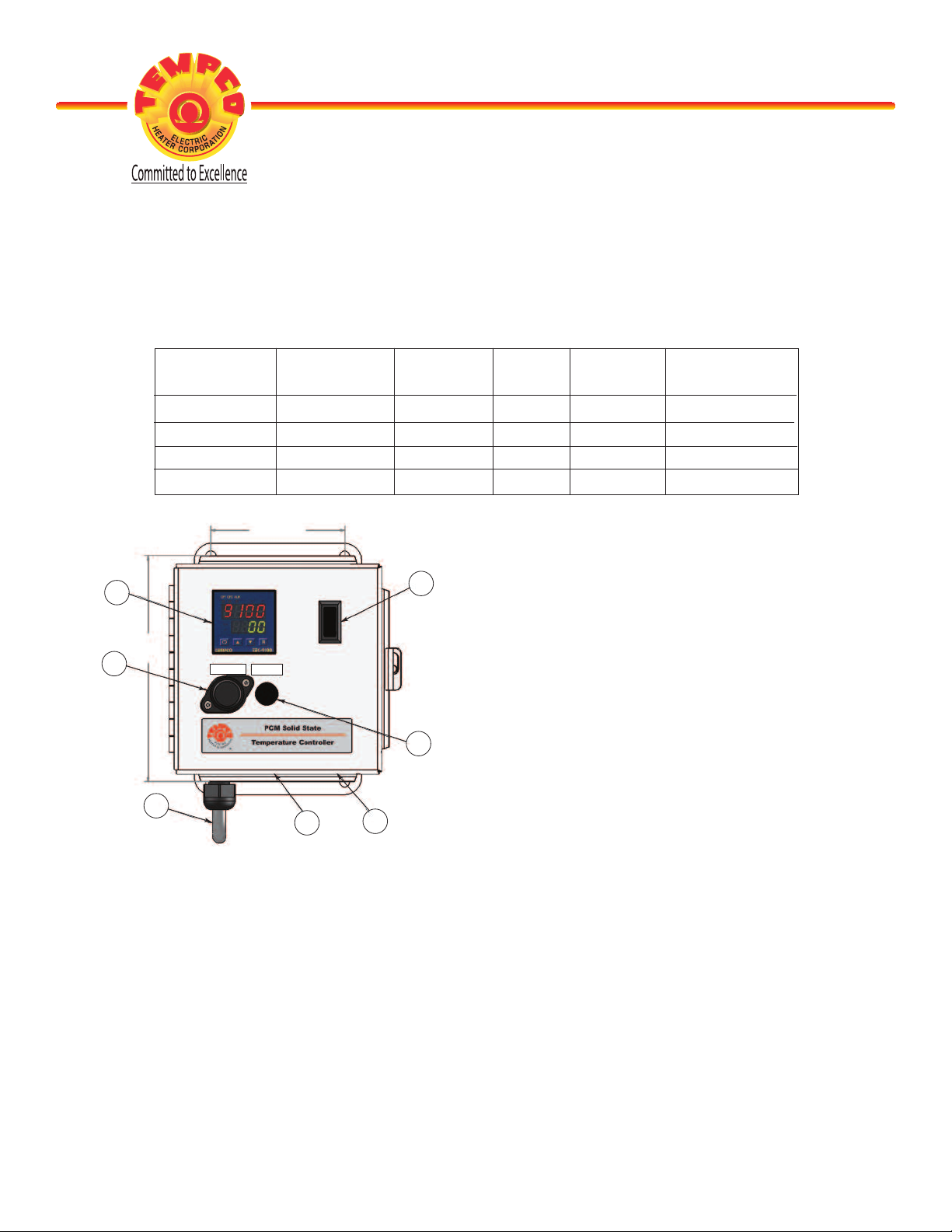
Instructions for Tempco Control Enclosure PCM10001 through PCM10004
Temperature Controller: Model TEC-9100, 1/16 DIN, Dual Display with PID Auto-tuning
Main Power Switch: Located on Front Panel
Part Number Input Voltage Max. Heater Maximum Thermocouple
(50/60 Hz) Amperage Fusing Wattage Sensor Input
PCM10001 120VAC 16 20amps 1920 Type J
PCM10002 240VAC 16 20amps 3840 Type J
PCM10003 120VAC 16 20amps 1920 Type K
PCM10004 240VAC 16 20amps 3840 Type K
1: TEC-9100 Controller
2: On-Off Switch
3: 1 Amp Control Fuse
4: 20 Amp Main Fuse (240V model has 2)
5: 120V or 240V Power Cord (20A)
6: 120V or 240V Heater Receptacle (20A)
7: Type J or K Thermocouple Jack
WARNINGS
1. Dangerous voltage capable of causing injury or death is present within this enclosure. Power to all
equipment must be disconnected before installation or beginning any troubleshooting procedures.
All wiring and component replacement must be made by qualified personnel only.
2. To minimize the possibility of fire or shock, do not expose this console to rain or excessive moisture.
3. Do not use this enclosure in areas where hazardous conditions exist such as excessive shock, vibration,
dirt, corrosive gases, oil or where explosive gases or vapors are present.
© 2016 Tempco Electric Heater Corporation (Revision 6/15/2016)
TEMPCO Electric Heater Corporation
607 N. Central Avenue
◆ Wood Dale, IL 60191-1452 USA ◆ 630.350.2252 ◆ Fax: 630.350.0232
E-mail: info@tempco.com
◆ Web: www.tempco.com
Page 1 of 10

WIRING (for safety, unplug unit prior to making any heater or sensor connections)
1. Attach the leads from your thermocouple to the provided standard thermocouple jack of the
same thermocouple type. Note the correct polarity: For type “J” and “K thermocouples, the
RED lead is (-) negative.
2. The heater output current is sourced directly thru the line cord. The bottom console output receptacle provides live controlled power for direct connection to your heater(s).
OPERATION
1. Verify the power switch is in the off position. Plug your heater into the straight-blade enclosure
connector. Plug the provided line cord from the console into a standard outlet. Switch on the
enclosure.
2. Using the up & down pushbuttons on the TEC-9100 controller, start out with the temperature
set low to test your system. If the setpoint temperature is being maintained, set your desired
temperature setpoint.
Note: The signal of the output circuit is wired through output 2 of the TEC-9100 which can
be used as a cut-out in the event of an over-setpoint temperature condition. This is
a deviation contact set to 30º F above the setpoint.
In the event of an over-setpoint temperature condition, output 2 will open, cutting
the control signal to the output relay.
This deviation setpoint can be changed by accessing “SP2” in the TEC-9100 (note
page 3 for user menu selection). This is not meant to be a redundant safety controller.
Refer to our TEC-910 for a safety controller.
3. Auto-tuning is recommended for initial set-up. Refer to page 7 of the attached manual for autotuning procedures.
SPARE/REPLACEMENT PARTS
Part Number Description
EHD-124-245 (1 or 2) Main fuse(s) rated 20 amps, 250V, Class CC, fast acting,
LittelFuse KLKR020 or equivalent.
EHD-124-276 Control fuse (1) rated 1 amp, 250V, 1/4 x 1¼", fast acting,
Bussmann ABC-1-R or equivalent.
EHD-102-218 Output plug — 20A 125V, 2-pole, 3-wire grounding,
NEMA 5-20R (PCM10001, PCM10003)
EHD-102-187 Output plug — 20A 250V, 2-pole, 3-wire grounding,
NEMA 6-20P (PCM10002, PCM10004)
TCA-101-101 Thermocouple plug, Type “J” (if PCM10001, PCM10002)
TCA-101-102 Thermocouple plug, Type “K” (if PCM10003, PCM10004)
Page 2 of 10
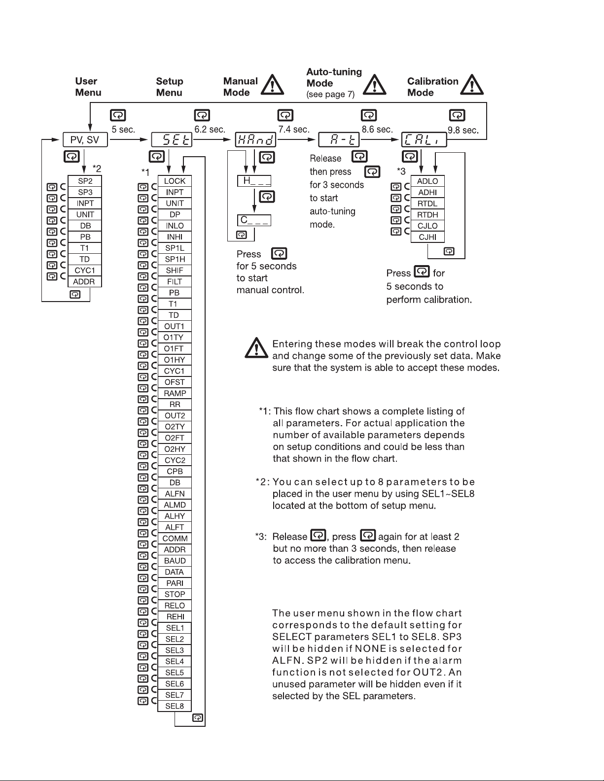
1–5 Menu Overview
Page 3 of 10
 Loading...