

Tempco Comfort 24V User Manual
1
User Guide GB
Analogic thermostat 24V 3-9
Guide d’utilisation F
Thermostat analogique 24V 10 -17
Bedienungsanleitung D
Analog Raumthermostat 24V 18 -24
Gebruiksaanwijzing Nl
Analoge thermostaat 24V 25-32
Instrukcja Użytkowania P
Termostat Analogowy 24V 33 -39
Manualul utilizatorului RO
Termostat analogic UFH – 24VAC 40-47
Инструкция по эксплуатации RU
TempCo Comfort – 24VAC 48-55
TempCo Comfort
24V

2
3
Installation and Operation Manual
IMPORTANT!
Before starting work the installer should carefully read this
Installation & Operation Manual, and make sure all instructions
contained therein are understood and observed.
- The thermostat should be mounted, operated and maintained by
specially trained personnel only. Personnel in the course of training
are only allowed to handle the product under the supervision of an
experienced fitter. Subject to observation of the above terms, the
manufacture shall assume the liability for the equipment as
provided by legal stipulations.
- All instructions in this Installation & Operation manual should be
observed when working with the controller. Any other application
shall not comply with the regulations. The manufacturer shall not
be liable in case of incompetent use of the control. Any
modifications and amendments are not allowed for safety reasons.
The maintenance may be performed by service shops approved by
the manufacturer only.
- The functionality of the controller depends on the model and
equipment. This installation leaflet is part of the product and has to
be obtained.
APPLICATION
- The UFH thermostat is developed to control and manage
actuators mounting on the manifold.
- The thermostat is normally used in conjunction with a complete
connecting box “UFH-MASTER” with or without “Heating & Cooling
module” to connect all electrical & hydraulic components of the
installation like a circulation pump, actuators...
- The controllers have been designed for use in residential rooms,
office spaces and industrial facilities.
Verify that the installation complies with existing regulations before
operation to ensure proper use of the installation.
SAFETY INSTRUCTIONS
Before starting work disconnect power supply!
- All installation and wiring work related to the controller must be
carried out only when de-energized. The appliance should be
connected and commissioned by qualified personnel only. Make
sure to adhere to valid safety regulations.
- The connecting boxes are neither splash- nor drip-proof.
Therefore, they must be mounted at a dry place.
- Do not interchange the connections of the sensors, actuators and
the 24V connections under any circumstances!
Interchanging these connections may result in life endangering
electrical hazards or the destruction of the appliance and the
connected sensors and other appliances.
4
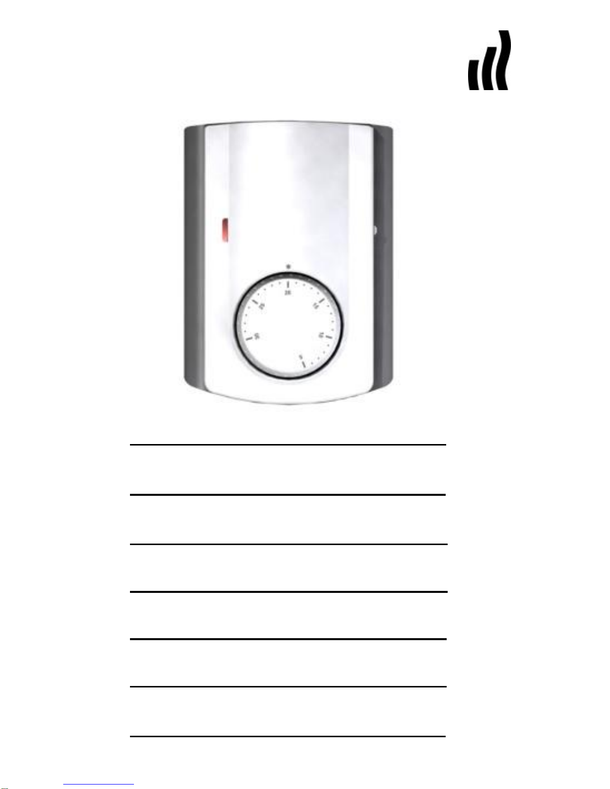
1 User Guide
UFH – 24VAC Analogue thermostat with NSB and H&C
function
Wired Analogue thermostat (24VAC) specially designed to
control your Under Floor Heating and cooling managed by
actuator (NC).
Flush Mounting version, standard fixing with 60mm axes.
Pilot wire for NSB function (-2°C)
3 working modes: Anti freeze, Reduced, Comfort
Thermostat with silent output.
Can drive directly the actuators, or can be connected to the
UFH connecting boxes range.
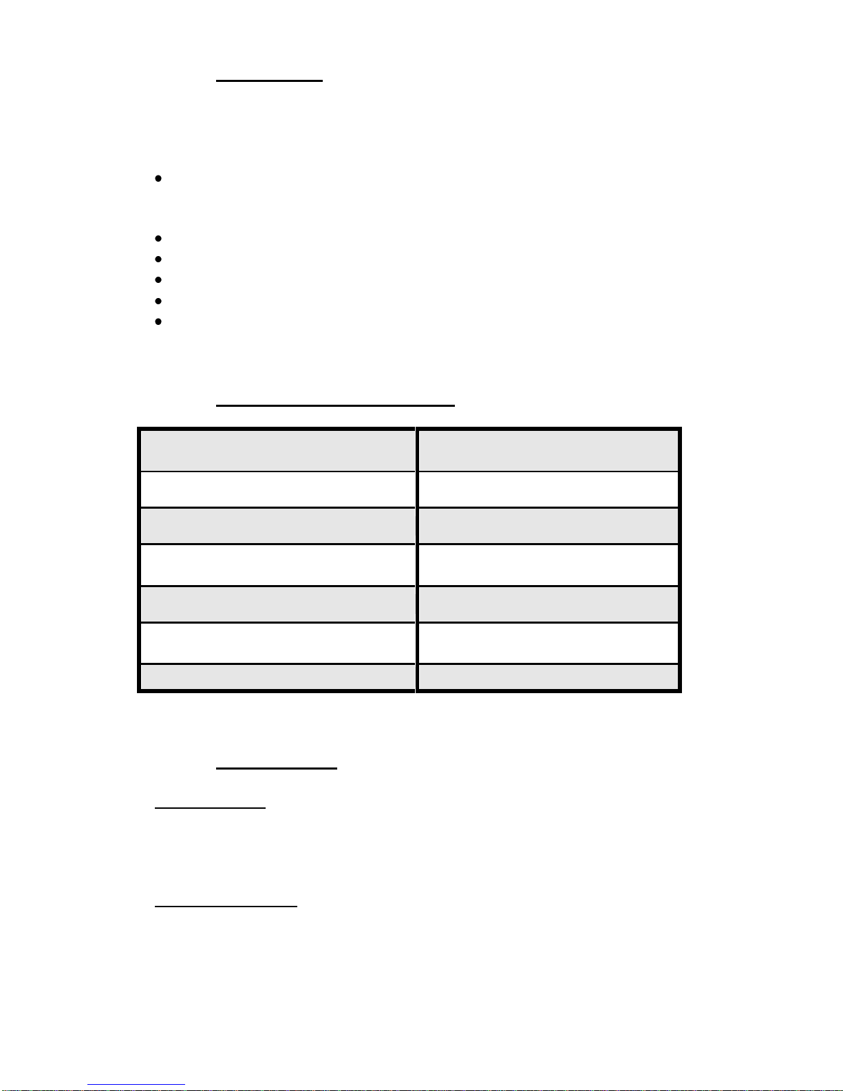
2 Technical characteristics
Measured temperature
precision
0.1°C
Operating temperature
0°C - 50°C
Setting temperature range
5°C - 30°C
Regulation
characteristics
hysteresis (ON/OFF) or
Proportionnal band (PWM)
Electrical Protection
Class II - IP30
Power Supply
Consumption
24VAC 50Hz
~ 0,5W
Output
TRIAC 24VAC 15W
3 Presentation
LED Indicator
Red: Heating demand indication.
Blue: Cooling demand indication
Specials displays
Red Blinking: Error on the internal sensor.
(Check the sensor)
Blue Blinking: Dry function activated.
(Risk of residual humidity on the house)
5
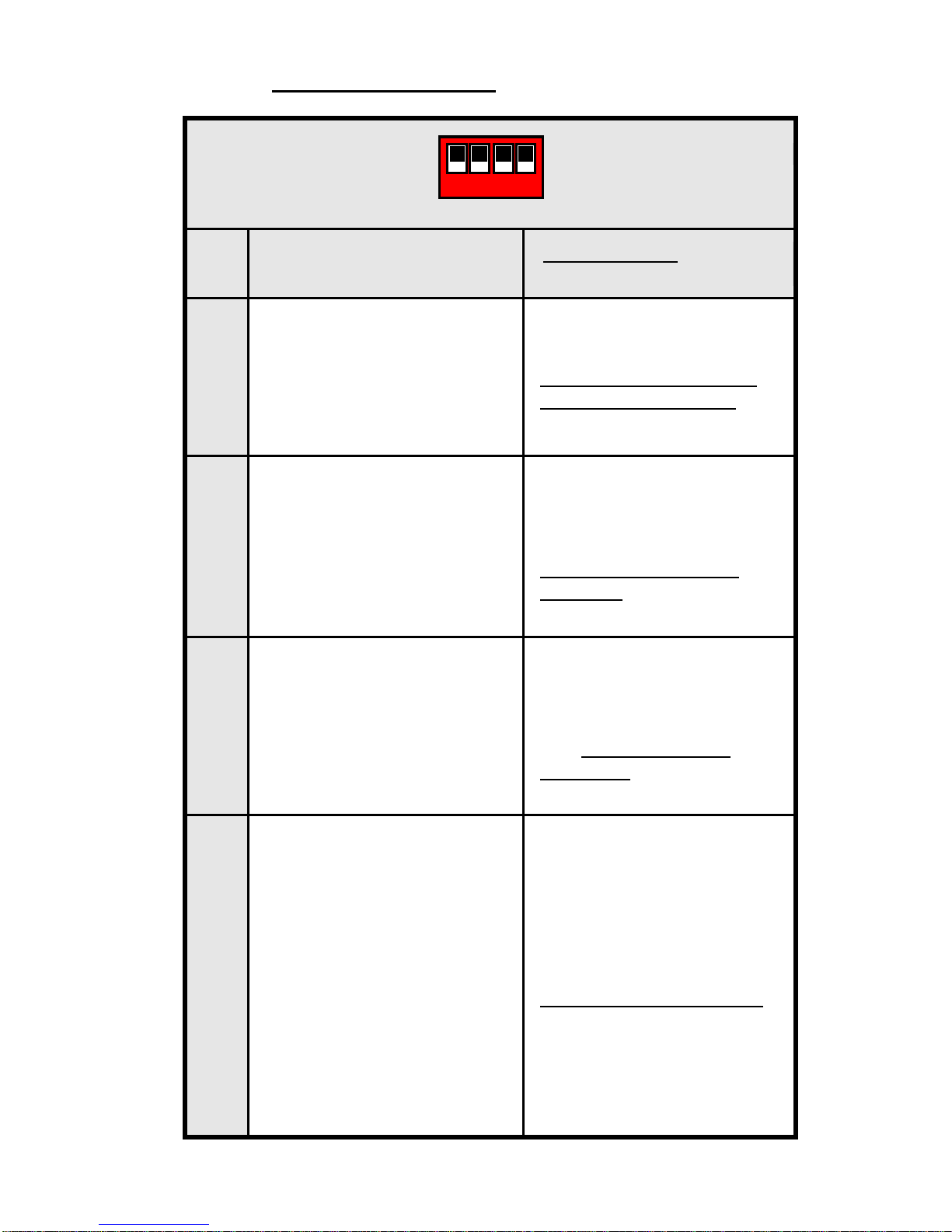
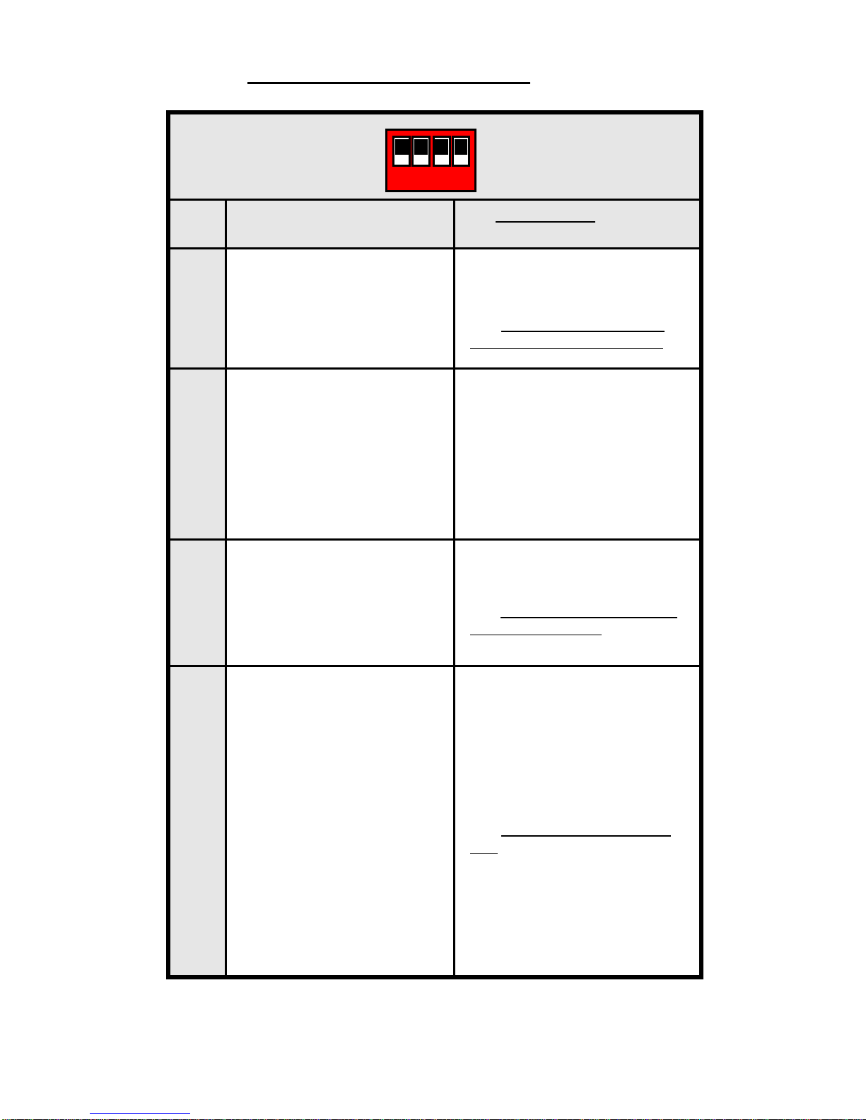
4 Configuration switch
N°
Description
Default setting and Other
possibility
1
Type of regulation
OFF: Hysteresis of 0,5°C
(ON/OFF regulation).
ON: Proportional Band of
2.0°C with 10Min cycle
(PWM regulation).
2
Cooling function
Example of use:
Cooling function should be
deactivated in room with
risk of residual humidity
(Bathroom, kitchen...)
OFF: Cooling function is
deactivated.
ON: Cooling function is
activated.
3
Night reduction (NSB)
during the night in cooling
mode.
OFF: never night reduction
in cooling mode
ON: Night reduction is
authorised
4
Type of night reduction
(NSB) during the night in
cooling mode.
The value of the Night Set
Back (2°C) will be added or
subtracted to the setting
temperature.
OFF: - 2°C during the night
Example of use:
for bed room, during the
night you need to cool this
zone
ON: +2°C during the night
Example of use:
for living room, during the
night you don’t need to cool
this zone
1 2 3 4
Off
On
6
5 How to use your thermostat
Anti Freeze mode: (Manual mode)
Simple installation without main zone programmer:
The antifreeze temperature (7°C) will be maintained in the room all
the time.
Installation with main zone programmer: (with or without
Heating and Cooling function)
In heating mode: (Winter)
The antifreeze temperature (7°C) will be maintained in the room all
the time.
In cooling mode: (Summer)
The thermostat will be switched Off.
REDUCED operating mode: (Manual mode)
Simple installation without main zone programmer:
The reduced temperature will be followed all the time. (Setting
temperature minus 2°C)
Installation with main zone programmer: (with or without
Heating and Cooling function)
The reduced temperature will be followed as described below:
In heating mode: (Winter)
The reduced temperature will be the setting temperature minus
2°C.
In cooling mode: (Summer)
The reduced temperature will be the setting temperature minus or
plus 2°C.
(See the configuration switch part “Switch N°2” for more
explanation).
Automatic operating mode:
Simple installation without main zone programmer:
The setting temperature will be followed all the time.
Installation with main zone programmer: (with or without
Heating and Cooling function)
In this mode your thermostat will follow the program (Comfort or
reduced) and order (Heating, cooling, Anti freeze, holiday…) of the
main zone programmer.
7
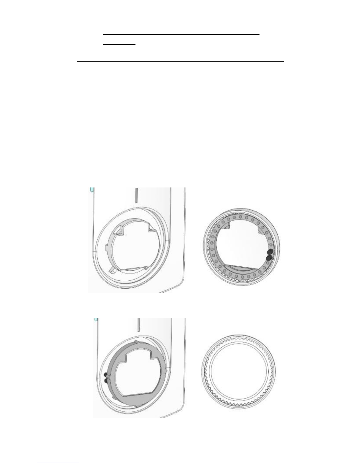
6 How to caliber and limit the setting range.
If your thermostat needs to calibrated, make these operations:
1. Put a thermometer in the middle of the room at 1.5 Meter
distance of the floor.
2. Wait 1 hour to be sure that your thermostat shows the correct
temperature.
3. Remove the setting button by pressing gently outwards with a
narrow screwdriver between the button and the cover. (pay
attention to avoid setting button rotation)
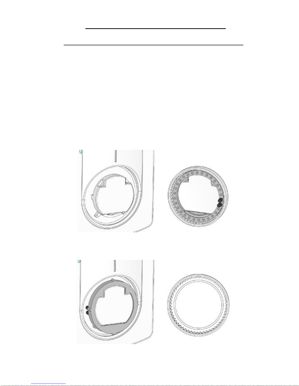
4. Remove the internal wheel from the button. (in grey Figure 1)
5. Put the internal wheel alone on the thermostat. (Figure 2)
6. You can now put the setting button on the thermostat, while
making corresponds real room temperature (showed by the
thermometer) and thermostat indexer.
Fig. 1
Fig. 2
8
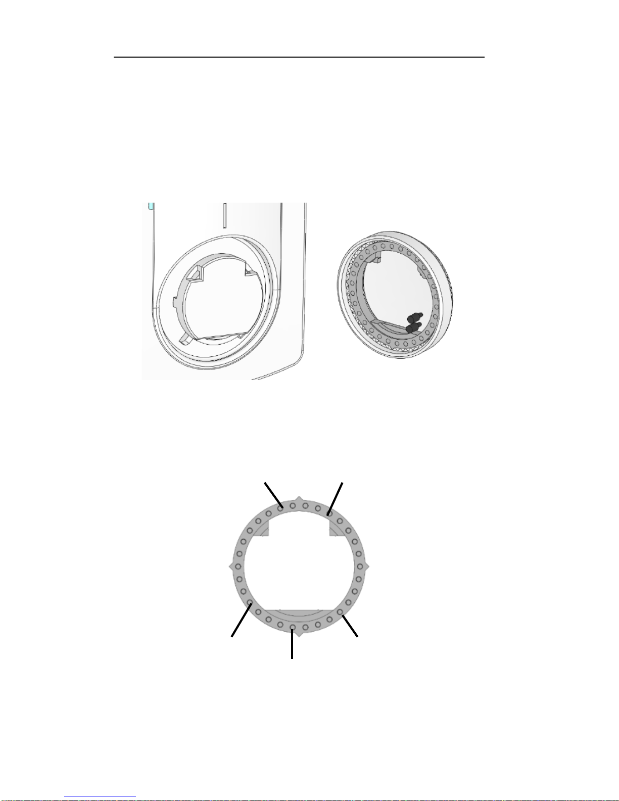
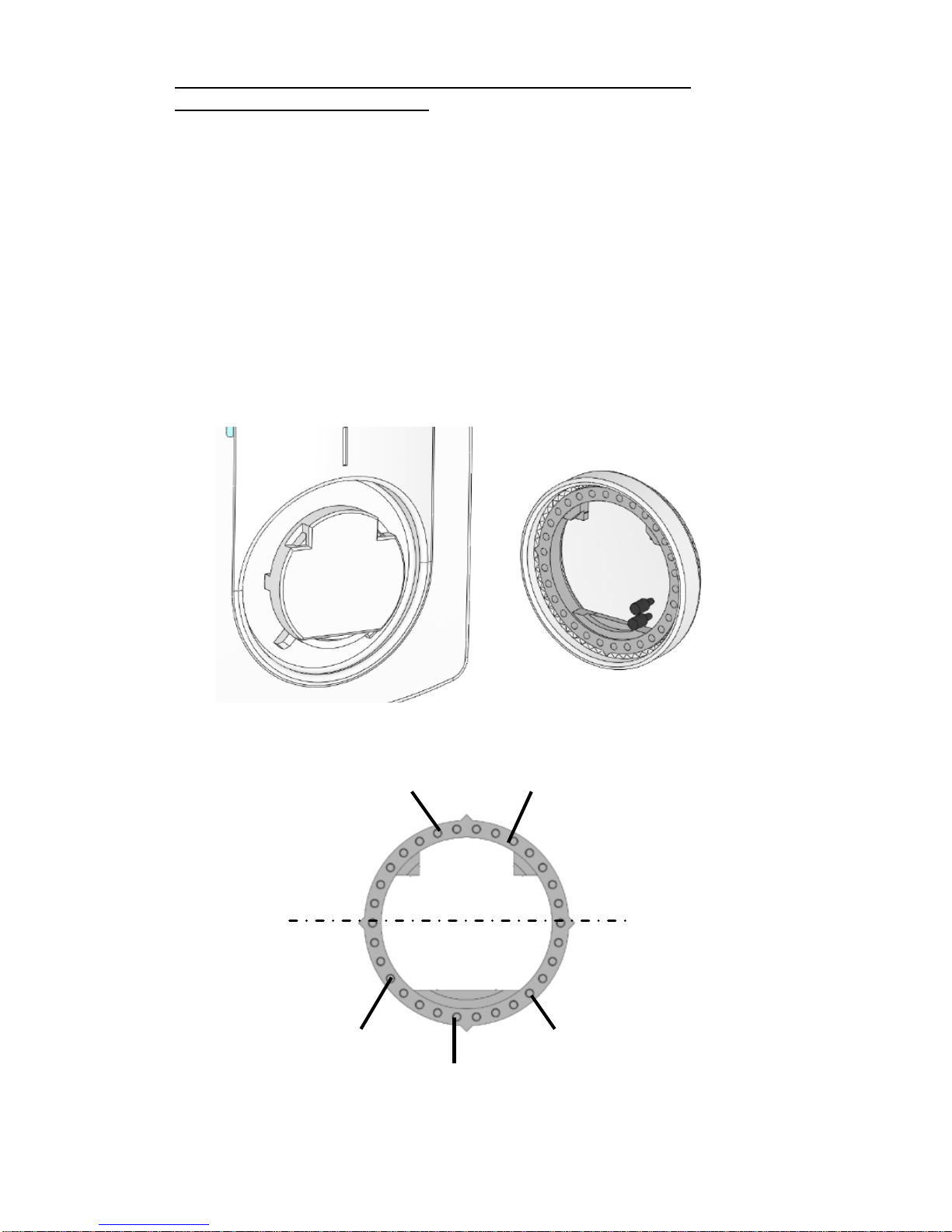
If your thermostat needs to be limited, make these operations:
1. Set the setting button on the middle of the new setting range.
2. Remove the setting button by pressing gently outwards with a
narrow screwdriver between the button and the cover.
3. Remove the dial pins and put in the desired holes to limit the
setting range of the thermostat. (Figure 3 et 4)
4. You can now put the setting button on the thermostat.
Fig 3
Fig 4
20°C 10°C
15°C
20°C 25°C
Max
Limitation
Min
Limitation

9
7 Notes
_____________________________________________________
_____________________________________________________
_____________________________________________________
_____________________________________________________
_____________________________________________________
_____________________________________________________
_____________________________________________________
_____________________________________________________
_____________________________________________________
_____________________________________________________
_____________________________________________________
_____________________________________________________
_____________________________________________________
_____________________________________________________
_____________________________________________________
_____________________________________________________
_____________________________________________________
_____________________________________________________
_____________________________________________________
_____________________________________________________
_____________________________________________________
_____________________________________________________
_____________________________________________________
_____________________________________________________

10
Manuel d’utilisation et d’installation
IMPORTANT!
- Avant de commencer les travaux, le monteur doit lire,
comprendre et observer les présentes instructions de montage et
de service.
- Seul un spécialiste en la matière est autorisé à effectuer le
montage, le réglage et la maintenance d’une régulation plancher
type UFH. Un monteur en formation ne peut réaliser de travaux sur
l'appareil que sous la surveillance d'un expert. La responsabilité du
fabricant conformément aux dispositions légales s'applique
uniquement dans le cas du respect des conditions précitées.
- Veuillez observer l'ensemble des instructions de montage et de
service lors de l'utilisation du programmateur de zones. Toute
utilisation autre n'est pas conforme. Le fabricant ne répond pas
des dommages occasionnés par une utilisation abusive de la
régulation. Pour des raisons de sécurité, aucune transformation ou
modification n'est admise. Seuls les ateliers de réparation
désignés par le fabricant sont habilités à réparer la station solaire.
- Le contenu de la livraison de l'appareil varie selon le modèle et
l'équipement. Sous réserve de modifications techniques !
Il est recommandé que l’installateur et l’utilisateur prenne
connaissance de l’intégralité de la notice, avant de procéder à
l’installation du matériel.
APPLICATION
- Le thermostat été développé spécialement pour le contrôle et la
gestion d’électrovannes montées sur les collecteurs de plancher
(nourrisses).
- Le thermostat est normalement utilisé en conjonction avec un
«MASTER-UFH» avec ou sans module «CHAUD / FROID», ils
permettront la connections de tous les composants électriques &
hydraulique de votre installation. (Circulateur, électrovannes,
thermostats)
Le module de régulation a été étudié pour un fonctionnement dans
un environnement résidentiel, bureaux ou en équipement
industriel.
Il est recommandé d’installer ce thermostat selon les règles de l’art
le tout en respectant les législations en vigueur.

11
INSTRUCTION DE SECURITE
Veillez toujours à déconnecter l’alimentation avant le montage
ou la manipulation!
Toute installation ou raccordement électrique sur le module doit
être réalisé dans des conditions de sécurité. Le module devra être
raccordé et manipulé par du personnel qualifié. Veuillez respecter
les législations de sécurité en vigueur, en particulier NF C15-100
(Normes d’installation ≤ 1000 VAC). Les boîtes de connexions ne
sont pas étanches aux éclaboussures ou aux projections d’eau. Il
doit donc être monté dans un endroit sec.
Prêter une attention particulière lors du câblage, n’inter changez
jamais les connections des sondes avec les connections de
puissances (24VAC), ceci pourrait provoquer des dommages
électriques voir la destruction des sondes ou la régulation.
Sujet à modification sans avis préalable!
12
1 Guide d’utilisation
UFH – 24VAC Thermostat analogique
Thermostat filaire 24Vac spécialement conçu pour la
régulation de plancher chauffant et rafraichissant hydraulique
géré par électrovanne thermique normalement fermée (NC).
Version encastrable (se fixe sur la plupart des boîtes avec
entraxe de fixation 60mm)
Fil pilote pour abaissement en mode ECO (-2°C)
3 modes de fonctionnement Hors Gel, ECO, Automatique
Thermostat à commande silencieuse.
Peut piloter directement les électrovannes ou être connecté à
une boîte de connexion de la gamme UFH.
2 Caractéristiques techniques
3 Présentation
Voyant d’état
Rouge : Thermostat en demande de chauffe.
Bleu: Thermostat en demande de froid
Affichages spéciaux
Rouge clignotant: Erreur sur la sonde interne.
(Vérifier la sonde)
Bleu clignotant: Fonction de déshumidification active
(Risque d’humidité dans la maison)
Précision de mesure
0.1°C
Température de
fonctionnement
0°C - 50°C
Plage de réglage
5°C - 30°C
Caractéristiques de
régulation
hystérésis (ON/OFF)
Protection
Class II - IP30
Alimentation
Consommation
24VAC 50Hz
~ 0,5W
Sortie direct
TRIAC 24VAC 15W Max.
13
4 Interrupteur de configuration
N°
Description
Réglage usine et autres
possibilités
1
Choix de la régulation
OFF: Hystérésis de 0,5°C
(Régulation dite ON/OFF).
ON: Bande proportionnelle de
2°C avec cycle de 10minutes.
(Régulation dite PWM)
2
Fonction Rafraichissement
Exemple d’utilisation:
La fonction de
rafraichissement devrait être
désactivée dans les pièces
humides comme les salles de
bains, buanderie…
OFF: Fonction rafraichissement
désactivée.
ON: Fonction rafraichissement
activée.
3
Fonction ECO en mode
rafraichissement.
OFF: Pas de fonction ECO en
mode rafraichissement.
ON: Fonction ECO autorisée en
mode rafraichissant.
4
Type de la réduction (ECO)
en mode rafraichissant.
La valeur de l’abaissement
ECO (2°C) sera ajouter ou
retranché à la température de
consigne pendant la nuit.
OFF: Abaissement de – 2°C
durant la nuit.
Exemple d’utilisation: Chambres
Durant l’été les chambres ont
besoin d’être rafraichies pendant
la nuit.
ON: Elévation de 2°C durant la
nuit.
Exemple d’utilisation: Pièces de
vie.
Durant l’été, les pièces de jours,
n’ont pas besoin d’être
rafraichies la nuit.
1 2 3 4
Off
On
14
5 Comment utiliser votre thermostat
Mode Hors Gel: (Mode manuel)
Installation simple sans centrale de programmation:
La température de hors gel (7°C) sera maintenue indéfiniment.
Installation avec centrale de programmation: (avec ou sans
fonction Chaud / Froid)
En mode Chauffage : (Hiver)
La température de hors gel (7°C) sera maintenue indéfiniment.
En mode rafraichissement : (Eté)
Le thermostat sera mis en arrêt.
Mode Réduit (ECO): (Mode manuel)
Installation simple sans centrale de programmation:
La température de réduction (ECO) sera maintenue indéfiniment.
(Température réglée sur le thermostat -2°C)
Installation avec centrale de programmation: (avec ou sans
fonction Chaud / Froid)
La température de réduction (ECO) sera suivie de la manière
suivante:
En mode Chauffage : (Hiver)
La température de réduction (ECO) sera maintenue indéfiniment.
(Température réglée sur le thermostat -2°C)
En mode rafraichissement : (Eté)
La température de réduction (ECO) sera maintenue indéfiniment.
(Température réglée sur le thermostat -2°C ou + 2°C)
(Voir la partie “Interrupteur de configuration” (Inter. N°2) pour plus
d’explication.
Mode Automatique:
Installation simple sans centrale de programmation:
La température ajuster sur le bouton de réglage sera suivie
indéfiniment.
Installation avec centrale de programmation:
Le thermostat suivra les ordres envoyés par la centrale de
programmation.
Les programmes (Jour/Nuit) ainsi que les modes de
fonctionnement (Chaud, Froid, Hors Gel, vacances...).
15
6 Comment calibrer et limiter la plage de
réglage.
Procédez de la manière suivante pour calibrer le thermostat
1. Tout d’abord, placez un thermomètre au milieu de la pièce à
une hauteur d’environ 1,5 mètre du sol.
2. Attendre environ 1 heure pour que la valeur affichée sur le
thermomètre soit correcte. (temps de stabilisation)
3. Tirez le bouton de réglage vers vous en faisant délicatement
levier avec un tournevis étroit entre la face avant et le
bouton.(attention à ne pas faire tourner le bouton).
4. retirez ensuite la couronne interne. (partie grise sur la Fig 1)
5. Repositionnez la couronne interne sur le thermostat. (photo
2)
6. Vous pouvez maintenant remettre le bouton de réglage en
place, en faisant coïncider la température lue sur le
thermomètre avec l’indexeur du thermostat.
Fig. 1
Fig. 2
16
Procéder de la manière suivante pour borner la plage de
réglage de votre thermostat
1. Positionnez le bouton de réglage au milieu de la plage
désirée
Exemple : vous désirez réduire la plage de réglage entre 15
et 25°C => Positionnez votre bouton sur 20°C.
2. Tirez le bouton de réglage vers vous en faisant délicatement
levier avec un tournevis étroit entre la face avant et le bouton.
3. Positionnez le bouton de réglage au milieu de la plage
désirée.
4. Retirez alors les pions de réglage et les positionner sur la
nouvelle plage de réglage. (photos a et b)
5. Vous pouvez maintenant remettre le bouton de réglage en
place.
Fig 3
Fig 4
20°C 10°C
15°C
20°C 25°C
Max
Limitation
Min
Limitation

17
7 Notes
_____________________________________________________
_____________________________________________________
_____________________________________________________
_____________________________________________________
_____________________________________________________
_____________________________________________________
_____________________________________________________
_____________________________________________________
_____________________________________________________
_____________________________________________________
_____________________________________________________
_____________________________________________________
_____________________________________________________
_____________________________________________________
_____________________________________________________
_____________________________________________________
_____________________________________________________
_____________________________________________________
_____________________________________________________
_____________________________________________________
_____________________________________________________
_____________________________________________________
_____________________________________________________
_____________________________________________________
 Loading...