

Page 1
INSTALLATION MANUAL
READ THIS ENTIRE MANUAL
INCLUDING THE WARRANTY SECTION
BEFORE STARTING THE INSTALLATION
WARNING!!
TO ENSURE THE SAFE AND
EFFICIENT OPERATION OF THIS
HEATER, SECTION 5 MUST BE
REVIEWED PRIOR TO STARTING
Temp-Cast 2000 Installation Manual February 2010
THE INSTALLATION
Page 2

2
TABLE OF CONTENTS
SECTION1 – INTRODUCTION
General Information 3
Site Preparation 3
Clearances 3
The Façade 4
Delivery & Handling 4
Tools 4
Additional Materials 4
Combustion Air Supply 5
SECTION 2 – CHIMNEYS & DAMPERS
General Requirements 6
Flue Connections 6
Masonry Chimneys 6
Factory-built Chimneys 7
Base-Exit Dampers 8
Installing the Roof-top Chimney Damper 9
SECTION 3 - STEP-BY STEP ASSEMBLY
Assembly Notes 10
Step-by-Step Installation 11
SECTION 4 - DOOR FRAMES & FACADE
The Door Frame Flange 37
Installing Arched Fire-Box Doors 38
Air Supply Doors 42
Clean-out (Soot) Doors 42
Installing "See-Through" Doors 43
Installing Square Fire-Box Doors 44
Installing Bake Oven Doors 46
The Trim Plate Option 47
Installing the Facade 48
The Masonry Cap 49
SECTION 5 - AVOIDING INSTALLATION ERRORS
SECTION 6 – CERAMIC FIBRE CUTTING PLAN
SECTION 7 –WARRANTY
PAGE #
50
51
53
Temp-Cast 2000 Installation Manual February 2010
Page 3
Section 1 - Introduction
SECTION 1: INTRODUCTION
GENERAL INFORMATION
The Temp-Cast 2000 is a modular "site-built"
fireplace kit. The assembled modules form the
"core" of the fireplace, including internal flue
passages. The Standard Fireplace package also
contains a cast iron fire grate, two soot cleanout
doors, refractory joint-sealing mortar, corrugated
cardboard spacers, gasket material, and assorted
fasteners.
READ THESE INSTRUCTIONS COMPLETELY
BEFORE BEGINNING THE INSTALLATION.
FAILURE TO FOLLOW THESE INSTRUCTIONS
MAY CREATE A FIRE HAZARD, HAMPER THE
PERFORMANCE OF THE FIREPLACE AND
VOID THE PRODUCT WARRANTY.
IMPORTANT: Review Section 5,
"Avoiding Installation Errors" before
beginning the installation!
3
CLEARANCES
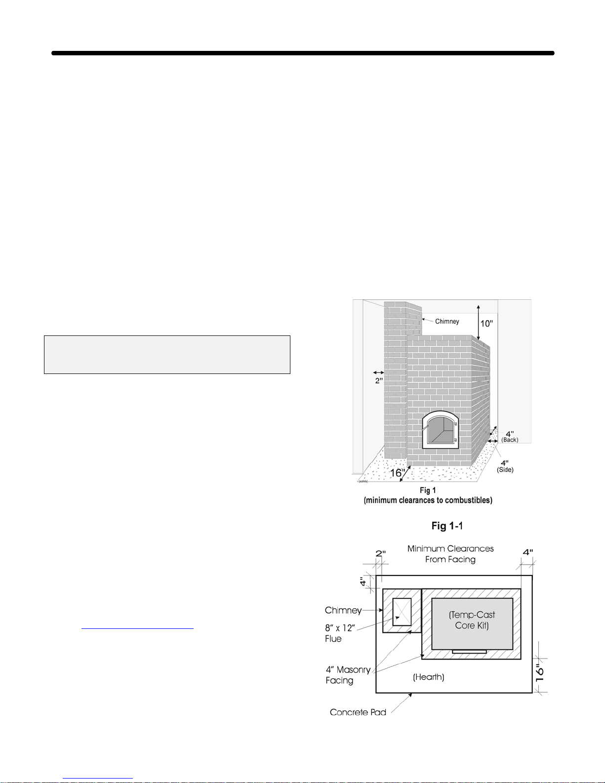
A minimum clearance of 4" (100mm) from the back
and sides of the completed fireplace (i.e. from the
masonry facing) to combustible materials is required.
The clearance required from the top of the heater is
10" (250mm).
48” (1200mm) clearance is required in front of the
door & a non-combustible hearth of 16” (400mm)
deep is required, extending 8” either side of the
door.( approx. 38” [1m] wide). Also, a clearance of
2" (50mm) is required between the chimney and any
combustible construction. (See Fig 1 & 1-1 below.)
SITE PREPARATION
The following instructions detail the assembly of the
Temp-Cast 2000 Fireplace, on a properly prepared
and supported concrete pad. Support requirements
are described in the Temp-Cast Planning Guide, and
related Plan Drawings. If you require assistance
with the support details for the fireplace or other
preparatory work, please contact your dealer or the
factory. If you are unsure regarding any aspect of the
installation of this product, please contact:
Temp-Cast Enviroheat Ltd, 3409 Yonge St,
Bedford Park Postal Outlet, Box 94059
Toronto, Ontario, Canada, M4N 3R1.
Tel: 416-322-5197 Fax: 416-486-3624
Toll-free 1-800-561-8594
Email: [email protected]
Temp-Cast 2000 Installation Manual February 2010
Page 4

Section 1 - Introduction
If necessary, a metal or masonry convection
shield may be placed between your fireplace
facade and the combustible structure, reducing
clearances by up to 67%. Contact your dealer,
local building inspector or the factory for details.
(In new construction, a non-combustible solid
masonry wall or metal stud and "cement-board"
wall will eliminate concern with clearances.)
FAILURE TO MAINTAIN THE MINIMUM
CLEARANCES TO COMBUSTIBLES MAY
CREATE A FIRE HAZARD.
THE FACADE
Once the core is assembled, it must be faced with
additional suitable heat-storing masonry material,
usually installed by a professional mason. (See also
Section 4.) Suitable facade materials include brick,
rock, fieldstone, or soapstone – concrete block
facings are not recommended. (Hollow units must be
filled. If using solid bricks, they should not be
perfectly flat on both sides - a depression is needed
to ensure that bricks do not move during thermal
expansion.) THE FACADE MUST BE BETWEEN
4" (100mm) & 6” (150mm) OF SOLID MASONRY,
STONE OR ROCK. (Substantially thinner facings
may not comply with building codes, due to higher
surface temperatures, requiring greater clearances to
combustibles. Thicker facings will make the heater
slower to respond & more difficult to regulate.)
DELIVERY & HANDLING
The fireplace kit weighs 2800 lbs and is delivered on
a wood pallet, covered with plastic. If unloaded by
forklift, it should be placed on a level and even
surface, so that parts will not fall when the strapping
is cut. Unpacking should be done by at least 2
persons, following the unpacking instructions.
As soon as possible after delivery, the fireplace
should be unpacked and dry assembled, to become
familiar with
complete and to check for damage. Visible damage
to the pallet or the contents must be reported
immediately to the delivery person and noted on
the shipping bill before accepting delivery.
Hidden damage or missing parts must be reported
to Temp-Cast and to the shipping company within
24 hours.
all the parts, to ensure the delivery is
4
The pieces must be handled with reasonable care to
avoid damage, although minor chips to corners and
edges are acceptable and do not affect installation or
performance. The modules should be stored indoors,
in a dry area. When possible, in cold weather, the
modules should be left in a heated area for a few days
prior to beginning the installation.
TOOLS
The following tools are required to simplify the
assembly process:
48" (1.2m) and 12” levels
powered cutting tool - options include:
1. 4” grinder with diamond blade
2. circular saw with diamond blade
3. masonry “water” saw or gas concrete saw (less
accurate & convenient on smaller cuts)
1/2" (12.5mm) hammer drill & masonry bits
heavy rubber mallet
2" (50mm) margin or pointed trowel
2" packing tape (e.g. “Scotch” tape)
black magic marker
pencil
utility knife
bucket, water & sponge
measuring tape
20 ft (10m) tie-down or web-clamp, for temporary
support of side channels (Step 18).
ADDITIONAL MATERIALS:
all masonry facing & chimney materials
Portland cement (to level the base)
chimney cleanout for rear connections (see
Section 4)
optional air supply door & frame (for slab-on-grade
installations - refer to Fig 1B)
optional chimney damper
6” or 8” combustion air supply duct (e.g.
galvanized duct - see next section)
Temp-Cast 2000 Installation Manual February 2010
Page 5
Section 1 - Introduction
COMBUSTION AIR SUPPLY:
The Temp-Cast heater requires an unrestricted air
supply for proper combustion and maximum
performance. (This section refers to the standard
Temp-Cast “arched” door & air-frame installation.
The Temp-Cast “square” door installation is
described in a separate
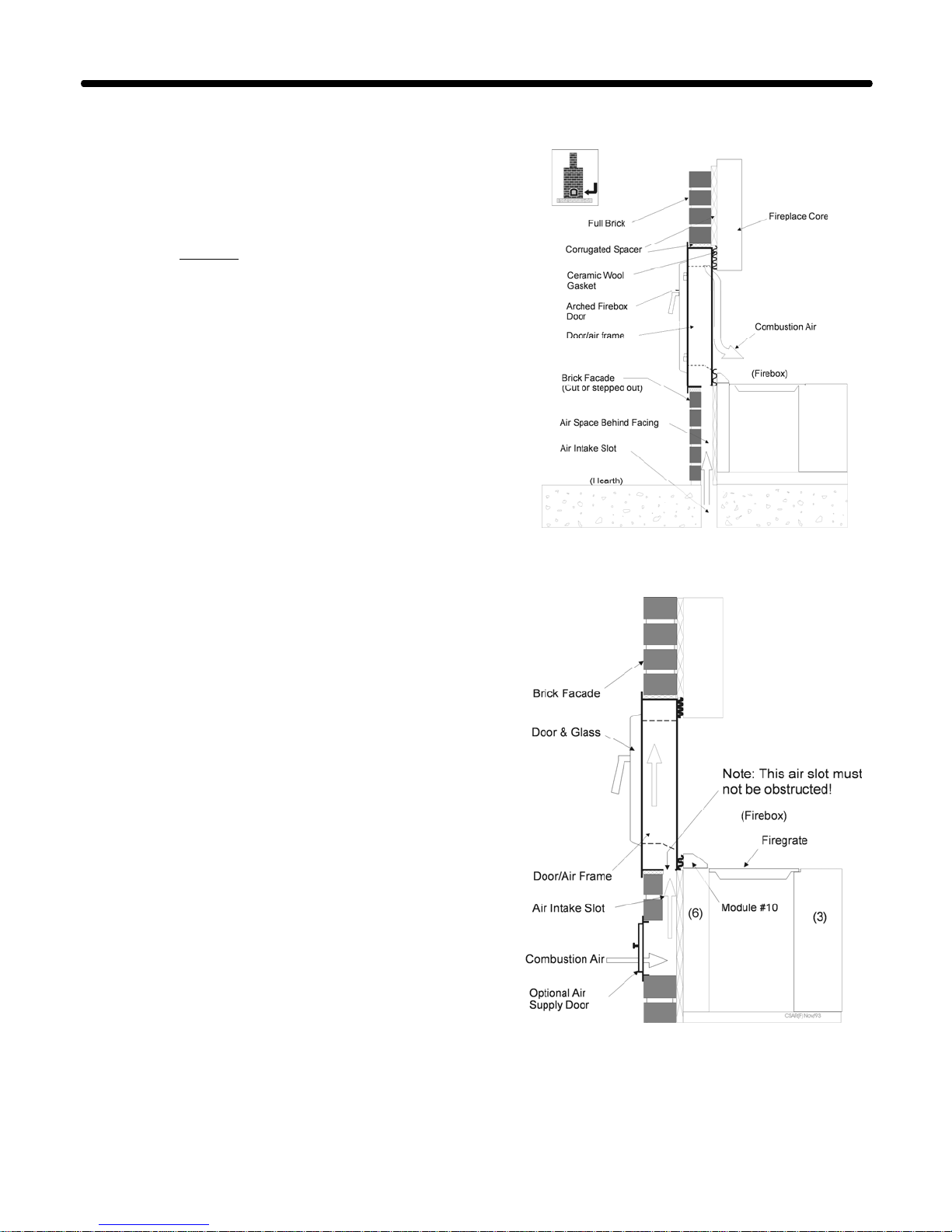
Combustion air can be drawn from outside or inside
the house and delivered by way of a 15" x 2"
(380mm x 50mm) air intake formed in front of the
heater during construction of the concrete floor pad.
Air is then directed up behind the facing masonry,
and into the hollow door frame through slots on the
bottom. The air travels up inside the door frame and
feeds the fire from above, creating an "air-wash"
across the doors to keep the glass clean. (See Fig. 1a)
If the installation is designed to use inside air from
the same room as the heater, (such as in a basement
installation ), then an optional "air supply door" must
be purchased and installed under the loading doors.
This will allow combustion air to be drawn from the
room, travel up behind the facade and into the hollow
door frame. (Refer to Fig. 1b).
In a basement installation, outside air can still be
brought into the fireplace, if ceiling height permits.
In this case, a raised hearth can be constructed, and
6" (150mm) of fresh air can be fed into this
(A "false" chimney can be used for this fresh air
supply.) The air is brought to the front of the heater
into a 15" x 2" (380mm x 50mm) masonry slot or
custom-fabricated "boot" and treated as a normal
outside air installation.
In a "See-Through" fireplace, 8” of combustion air
must be supplied and divided equally to both door
frames to provide an "air wash" for each door glass.
(See Fig. 16)
manual.)
structure.
5
Fig 1a
Temp-Cast 2000 Installation Manual February 2010
Fig 1b
Page 6
SECTION 2: CHIMNEYS & DAMPERS
GENERAL REQUIREMENTS
Temp-Cast fireplaces require an approved
chimney system for safe and satisfactory
performance. Code-approved masonry and
factory-built chimney systems are both
acceptable.
In addition to building code requirements, every
chimney system should:
extend straight up from the base of the
fireplace
be at least 18 ft (5.5m) in height
have an access at the base, with a tight-
fitting metal door, for chimney cleaning
have a cross-sectional area of at least 50 sq.
inches (320 sq cm)
NOT BE CONNECTED TO ANOTHER
APPLIANCE OR TO ANY AIR DUCTS
FLUE CONNECTIONS
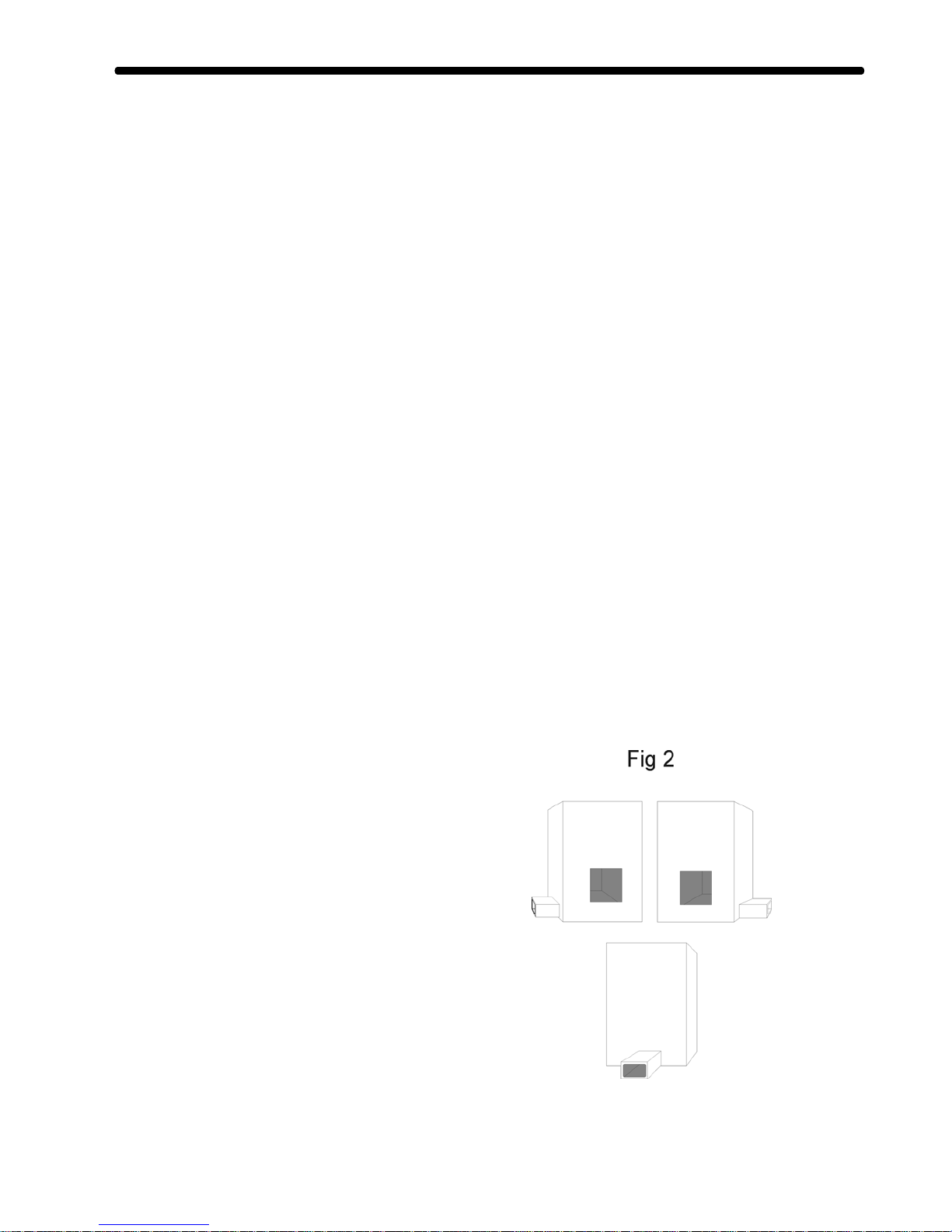
The chimney connection is made at the bottom
of the fireplace, in the first course. The
connection can be made on either side of the
fireplace or through the back wall, into the cross
manifold. (Refer to Fig. # 2). The flue
connection can be up to 5 ft. long, creating
heated benches & allowing additional flexibility
in chimney locations.
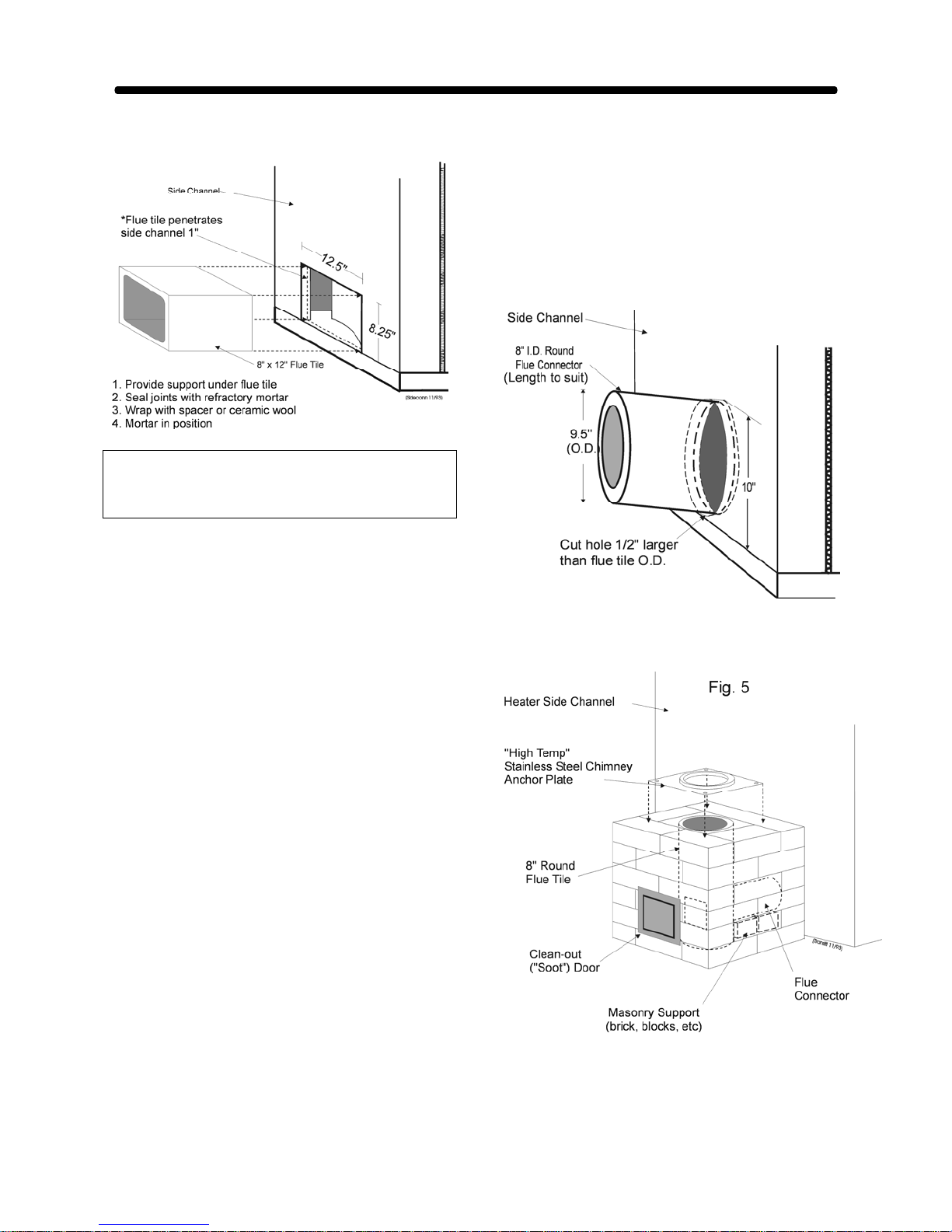
For a side connection, the side channel (Part #
30 or 31) is cut to receive the connector. (see
step 18.) Make this cut carefully so that a
smooth transition from the fireplace to the
chimney results, free of
of the escaping smoke. Use joint sealing mortar
to make it completely smoke tight. The
connector piece penetrates the fireplace side
channel about 1" (25mm), but care must be
taken to ensure that it does not protrude past the
inner edge of the side channel. (See Figs. # 3
and 4.)
If the connection is made at the back of the
fireplace, the cross manifold (Part #3) is cut to
obstructions to the flow
receive the flue connector. This joint must
also be smoke-tight. (See also Section 3,
Step #3.)
MASONRY CHIMNEYS
Due to the thermal mass storage capability
of masonry chimneys, we recommend them
over factory-built chimneys, provided they
are completely inside the home & fitted with
a damper.
Masonry chimneys should have carefully
aligned flue liners, with joints that are
smoke-tight and joined with refractory
mortar. The inside surface of the liner
should be smooth, with all excess mortar
removed. Refractory, clay and UL/ULC
listed stainless steel are all acceptable liners.
An access for a chimney cleanout can be cut
in the first vertical flue tile. (See Fig #10)
6
Temp-Cast 2000 Installation Manual February 2010
Page 7
Section 2 – Chimneys & Dampers
7
Fig 3
A 4” grinder with a diamond blade is ideal for
cutting accurate & neat holes in the refractory
concrete modules.
FACTORY-BUILT CHIMNEYS
We do not recommend exterior chimneys, (see
Sec. 4 of the Temp-Cast Planning Guide) but if a
chimney on the outside of the house is
unavoidable, then an insulated factory-built (e.g.
"HT" or 2100F.) chimney is the better choice.
When a factory-built chimney is started at the
floor level, there will not be sufficient space to
access the clean-out cap under it. In order to
provide a clean out access, one of the following
2 methods is suggested.
Create a masonry connection to the fireplace,
with 8" (200mm) round flue tile. Add vertical
sections of 8” round flue tile, with a clean-out
access built into the first vertical section. Wrap
the horizontal tile and the first vertical flue tile
with “ceramic wool” blanket & ensure they
cannot be dislodged. Continue with flue tile &
masonry to the point where the transition to
factor-built chimney is wanted – often the
masonry is extended to the first ceiling. If a
roof-top damper is to be installed, the cable
protector for the damper cable must be built into
the masonry chimney where it will be accessible
for daily use – we recommend at least 6 feet
from the floor. Install an anchor plate approved
for the factory-built chimney, on top of the last
masonry section - the factory-built chimney
continues from this point. (See Fig. 5.) If the
factory-built chimney will also be enclosed in
masonry, the layout of the first masonry courses
must take this into account. (Confirm this
connection method with your local building
official.)
Fig 4
Temp-Cast 2000 Installation Manual February 2010
Page 8
Section 2 – Chimneys & Dampers
8
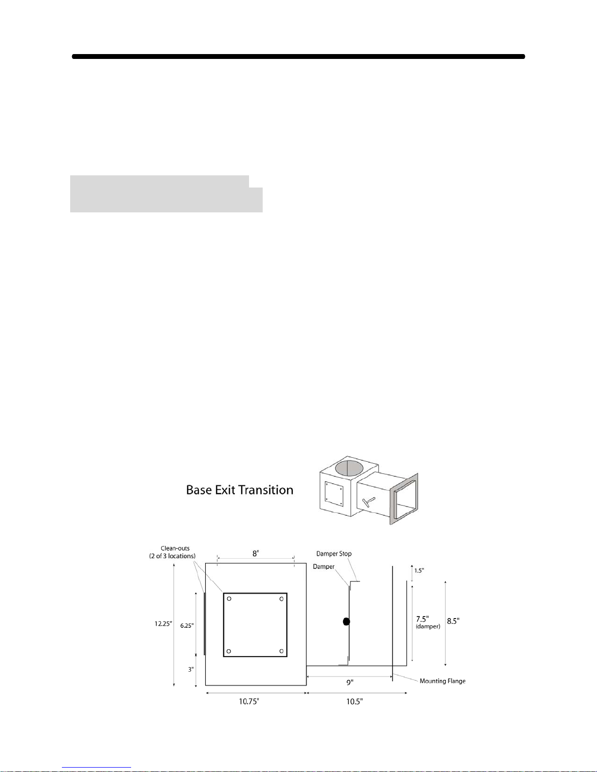
BASE-EXIT DAMPER/TRANSITION
A Temp-Cast base-exit damper/transition is
another method to make a suitable connection
from the heater to a factory-built chimney, and
also incorporates a damper & cleanout access
that is not otherwise possible with factory-built
chimneys. (See Fig 6.)
If you use a damper of any kind, be
certain to read the cautions regarding
carbon monoxide, in the next section.
The following details the installation of the
Temp-Cast base-exit damper/transition.
1. At Step 18, position the base-exit
damper/transition, sitting on the
concrete slab. Mark where the damper
will be installed into the side channel
(Part #30 or 31) or rear manifold (Part
#3), and cut a 9½” x 9½” opening.
2. Cut the damper rod to length, if
required, to extend beyond the masonry
which will enclose the entire assembly.
3. Attach the handle to the rod with the nut
extender and nuts supplied. Check the
operation of the damper to become
familiar with its operation. (The handle
is usually shipped inside the damper.)
4. Attach a strip of ceramic wool to the
outside of the side channel around the
damper opening, with high-temperature
silicone. Lay a strip of ceramic wool on
the bottom edge of the opening and
insert the base-exit damper/transition.
Insert the damper into the opening and
slightly compress the ceramic wool – it
may be helpful to temporarily support
the damper box until masonry work has
been started around it.
5. Cover the damper rod so that it will not
be inadvertently cemented in position
during installation of the masonry facing
– flexible cardboard or ½” copper pipe
(not supplied) may be used for this.
6. With at least 3 metal screws, attach an
approved masonry adapter to the top of
the damper assembly & install the first
vertical section of factory-built chimney.
7. Enclose the entire damper assembly
with at least 4” of solid masonry,
leaving an access for the cleanout. (If
the factory-built chimney will also be
enclosed, the first masonry courses must
take this into account.)
Other methods of connecting factory-built
chimneys may also be acceptable. Consult the
chimney manufacturer, a certified installer or
your local building official.
Fig 6
Temp-Cast 2000 Installation Manual February 2010
Page 9
Section 2 – Chimneys & Dampers
9
INSTALLING THE ROOF-TOP
CHIMNEY DAMPER
An optional “roof-top” chimney damper is
recommended to allow the chimney to be closed
off when the fire is out. This will let the
chimney mass hold additional heat and greatly
improve the overall heating efficiency of the
system. (Refer to the Temp-Cast Owner's
Manual for proper use of the chimney damper.)
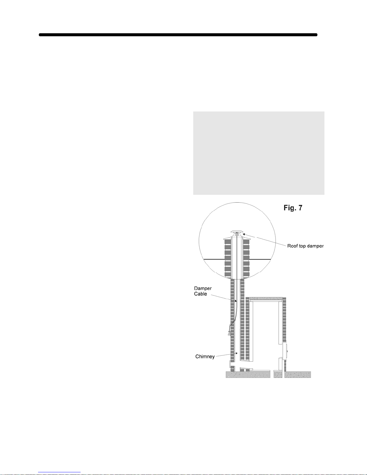
The damper is cemented to the top of the
uppermost flue tile of the chimney, and is
controlled by a cable through the centre of the
chimney. (See Fig. 7) The cable is routed
through the side of the flue tile during
construction of the chimney and masonry facing.
(Note: Installation of the damper cable is greatly
simplified if the protective sleeve and steel
cable are installed in the desired area when the
chimney is being built. If this has not been done,
then a string will have to be fished through the
sleeve & secured to the steel cable.) Attach the
cable bracket to the outside of the chimney in a
convenient, unobtrusive location, but always out
of the reach of small children.
For 8” round chimneys, including factory-built
models, a Round-to-Square adapter and a 13” x
13” damper will be required.
NOTE: When a stainless steel (i.e. “factorybuilt”) chimney is used, penetrating the steel
chimney is not permitted. Alternatives
include:
1. Installing a Temp-Cast Base-Exit Damper,
construct a short section of masonry
chimney, install an approved masonry
adapter part and continue with factory-built
chimney through the roof. (See Fig 6.)
2. Starting the installation with a Temp-Cast
Base-Exit Transition, with or without an
integral damper. For exposed chimneys, a
Temp-Cast Base-Exit Transition/Damper
must be used. If the chimney is to be
enclosed to the first ceiling or through to
the roof, you can use the same Temp-Cast
Base Exit Damper/Transition, or obtain an
adapter with a built-in damper, which can
be installed with the first section of
“factory-built” chimney. This permits a
more effective damper, much higher up in
the chimney system. In either case, the
whole chimney assembly and transition can
be enclosed in masonry.
CAUTION: Whenever a full-closure damper is
used, care should be taken to ensure that the fire
is completely out before the damper is shut.
Closing the damper prematurely could cause
combustion gases, especially carbon monoxide,
to be spilled into the home. Carbon monoxide
has the potential to be fatal. We therefore
strongly recommend installation of a carbon
monoxide alarm, available where smoke alarms
are purchased, whenever a damper is used with a
Temp-Cast masonry heater.
Temp-Cast 2000 Installation Manual February 2010
Page 10
Section 3 - Step-By-Step Assembly
SECTION 3: STEP-BY-STEP ASSEMBLY
ASSEMBLY NOTES
1. Dry-assemble the heater upon
delivery, to check the condition of all
parts and to familiarize yourself with
the modules. (If all of the parts are not
numbered, you may find it helpful to do
so, using this manual, before taking
the unit apart again.)
2. Cutting of flue tiles and fireplace
modules should be done outdoors due
to the excessive dust created. WEAR
SUITABLE EAR, EYE AND LUNG
PROTECTION.
3. A 4” grinder with a diamond blade is
best for cutting holes in flue tiles and
fireplace modules. Or round holes can
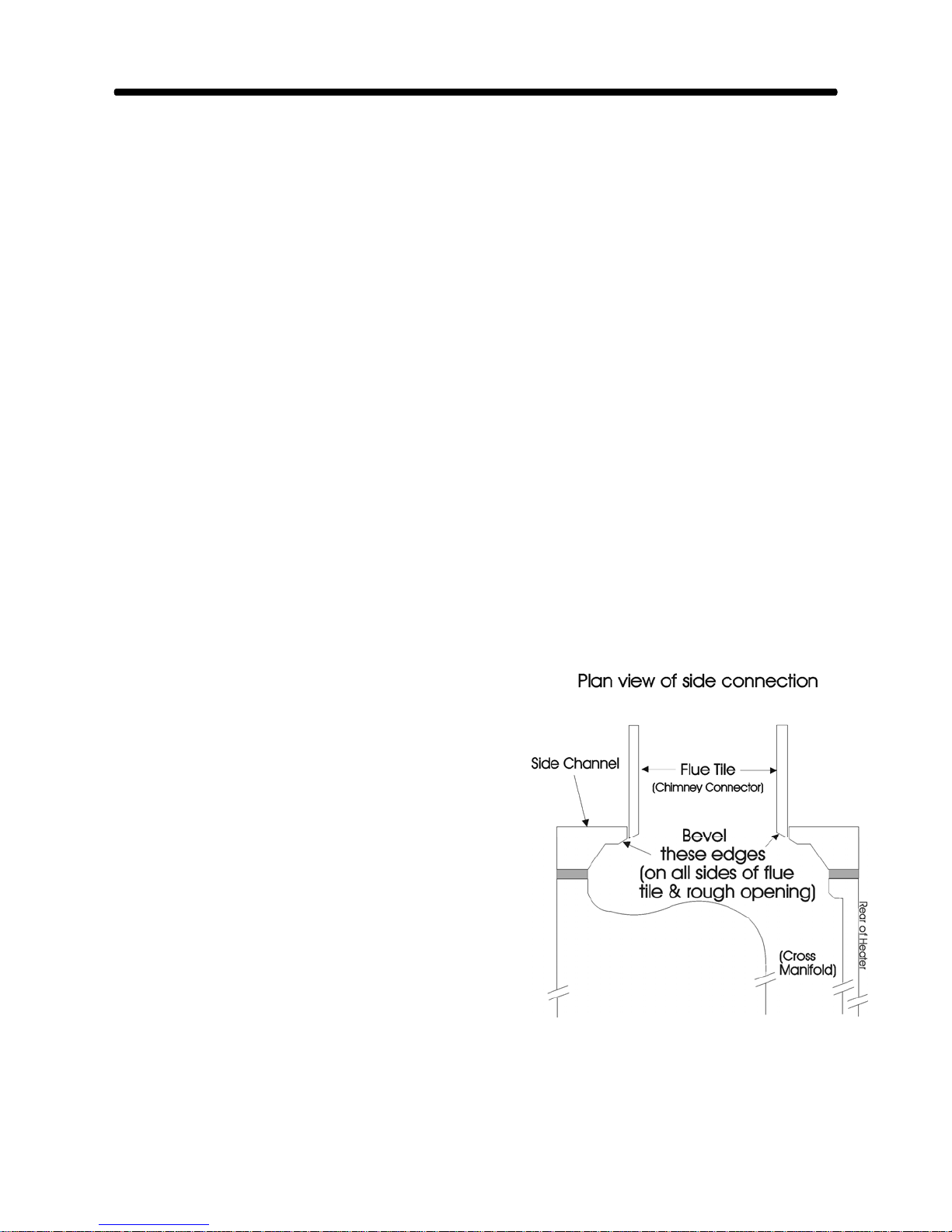
be cut as six or eight-sided shapes
with a gas, water or circular saw or
drilled every inch (25mm) and then cut
with a reciprocating saw fitted with a
masonry blade. Rounding or beveling
the inside edges of the hole in the
module creates the least resistance to
the flow of smoke and gases,
maximizing draft and performance.
(See Fig. 8)
4. When using the ceramic-fibre gasket
material, it should only be slightly
compressed. Compressing it too
much will defeat its purpose as an
expansion gasket. (A small amount of
refractory mortar can be used to
cement the gasket in position.)
5. Refractory casting occasionally leaves
behind rough spots or small bumps on
the modules. If these rough spots
should occur in a joint between 2
modules, they may prevent a tight joint
and make installation of subsequent
parts more difficult. Remove any such
10
bumps with a rasp or scraping tool
before assembling.
6. Refractory mortar should be used
sparingly, applying a small (1/4” to
3/8”) bead between modules. The
finished joint should have a very thin
skin of refractory mortar, which is the
strongest. (In addition, the parts will
only fit properly if the thinnest possible
joint is created.) Apply a small amount
on the outside edges of the part, where
indicated by the shaded areas. Do not
use a full bed of mortar. Seat the
parts completely, using a rubber
mallet, so that a little mortar squeezes
out. After each course, scrape off and
save excess mortar for possible later
use. Periodically wipe the modules
inside and out with a damp sponge to
ensure that excess mortar has not
been left behind.
Fig. 8
Temp-Cast 2000 Installation Manual
Page 11
Section 3 - Step-By-Step Assembly
11
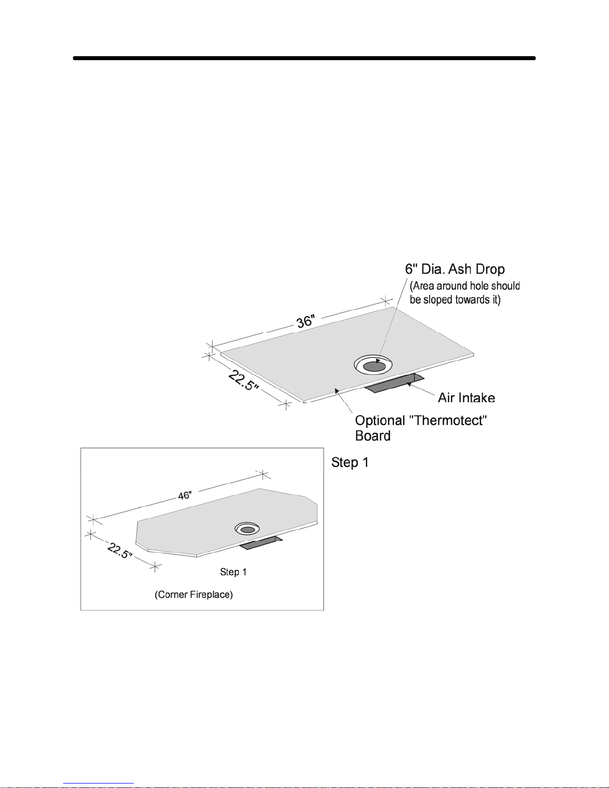
STEP 1: "THERMOTECT" INSULATING BOARD
If an optional insulating board is to be installed, it is installed before starting the Levelling Pad.
Cut the board to size as indicated and place it in position. Check that it is square to the concrete
floor pad. Ensure that the air intake hole is located immediately in front of the board and centered.
(It is also advisable at this point to double check that there will be sufficient clearances to
combustible construction around the fireplace.)
If you have followed the Temp-Cast Planning Guide, the area around the 6" diameter Ash Drop
hole in the concrete pad will be sloped towards the hole for a few inches all around. Cut an
appropriately sized hole in the insulating board so that the sloped area around the hole is not
obstructed. Lay the board in position as illustrated.
Temp-Cast 2000 Installation Manual
Page 12
Section 3 - Step-By-Step Assembly
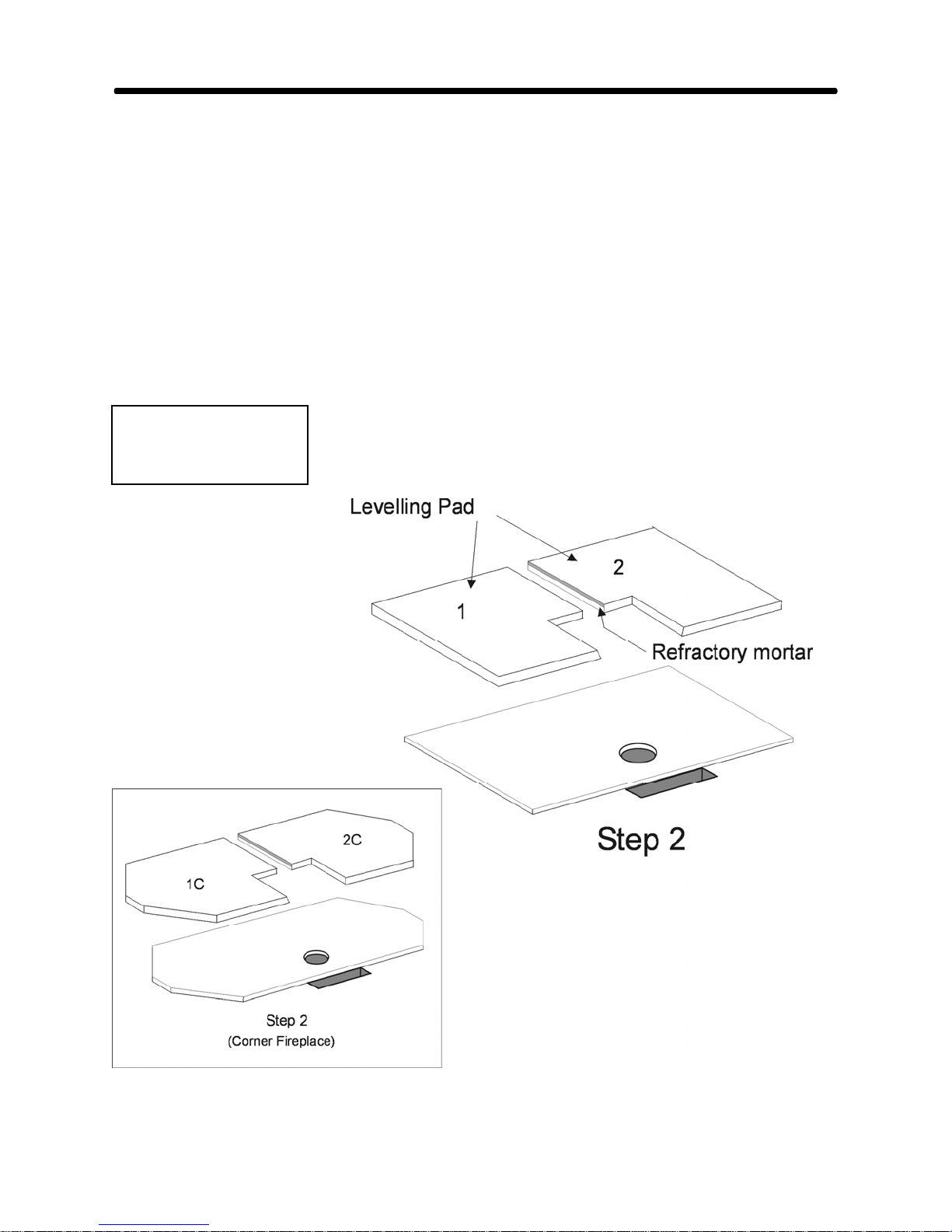
STEP 2:
"Dry" assemble (i.e. without mortar) the two halves of the Leveling Pad (Part #1 & #2) on the
"Thermotect" board (optional), or on the concrete floor pad, so that the air intake slot is not
obstructed and is centered in front of the Leveling Pad. Ensure that the 6" (150mm) diameter ash
drop is located within the cut-out section of the base. CHECK THAT THE FLOOR IS
REASONABLY LEVEL BEFORE STARTING TO INSTALL THE LEVELLING PAD ADDITIONAL MORTAR MAY BE NEEDED TO LEVEL IT AS REQUIRED.
Lay the two halves of the Leveling Pad in a 1/2" (12mm) bed of common mortar, using refractory
mortar between them. Using the 48" level, tap the base into the mortar, ensuring that it is level.
Before the mortar has set, tap down along the centre-line of the leveling pad, so that the centre of
the pad is about 3/16” lower than the sides. (See illustration below.) This centre-line gap will
ensure that parts in the upper courses lean in slightly, simplifying installation.
Weights
#1 & 2 - 49 lbs
#1C & 2C - 59 lbs
12
Temp-Cast 2000 Installation Manual
Page 13
Section 3 - Step-By-Step Assembly
13
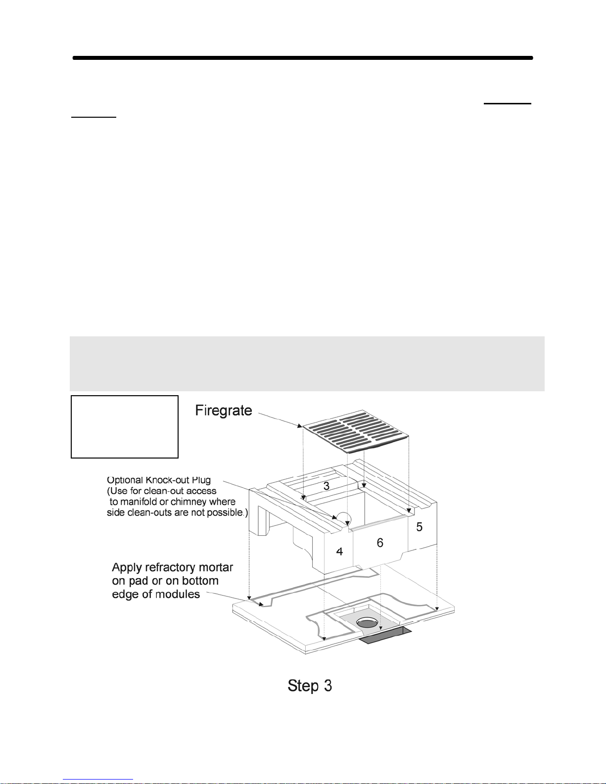
STEP 3:
When the Leveling Pad can support weight, dry assemble the first course of modules, including
the grate, as in the accompanying drawings, to check for proper fit. This course must be centered
on the Leveling Pad, so that equal space is left on both sides for the heat exchange channels - mark
the correct placement with a pencil.
If the chimney is to be connected at the rear of the fireplace, mark the cross manifold (#3) to be
cut for the flue connection. Take this part outdoors and cut a hole for the flue connector being
used. For flue tile or HT chimney, cut the hole the same size as the inside dimensions of the flue
connector. The flue connector or HT adapter will then be mortared or attached to the outside of
the cross manifold - Part #3. (Holes for a side connection are discussed at Step 18.)
Once the layout of fireplace and chimney connection, all dimensions and locations of cleanout
doors have been confirmed, draw a line on the Leveling Pad to mark the outside edges of the base
course. Now remove the modules, (cut the flue hole in #3 if required) and re-assemble, using a
small amount of the refractory mortar provided on the bottom edges and between modules. Seat
the parts with the rubber mallet, then reach inside the cross manifold and wipe off all excess
mortar.
NOTE: once final assembly has been started, the entire core should be assembled in a continuous
operation, so that minor adjustments to previous courses can be made before the refractory mortar
has set. Place the fire-grate in position, which should fit loosely to allow for expansion. Cover it
to keep clean.
Weights
#3 - 61 lbs
#4& #5 - 82 lbs
#6 - 22 lbs
Temp-Cast 2000 Installation Manual
Page 14
Section 3 - Step-By-Step Assembly
14
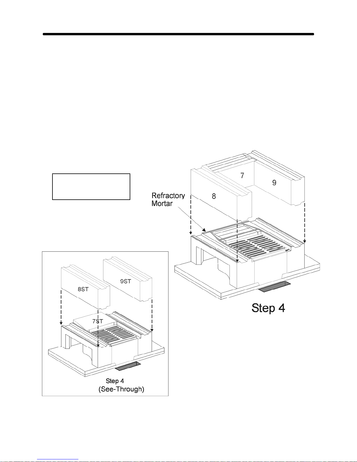
STEP 4:
Assemble the second course, parts #7, #8 & #9. A small bead (½”) of refractory mortar is laid on
the outside edges where the two parts meet. (The bead can be laid either on the part being laid on
or the previous part - whichever is easier.) Note that the parts are numbered in the order that they
should be placed. (For a Temp-Cast "See-Through" fireplace, these 3 parts are slightly different,
as in the accompanying illustration.)
Use the rubber mallet to seat the modules. Remove excess mortar and wipe inside and out with a
damp sponge as work progresses.
NOTE: When installing the modules on this course and subsequent courses around the firebox
opening, take care that the parts are flush at the front of the fireplace. This will produce the most
level surface on which to install the door frame later.
Weights
#7 - 52 lbs
#8, #8ST, #9, #9ST - 68
Temp-Cast 2000 Installation Manual
Page 15
Section 3 - Step-By-Step Assembly
15
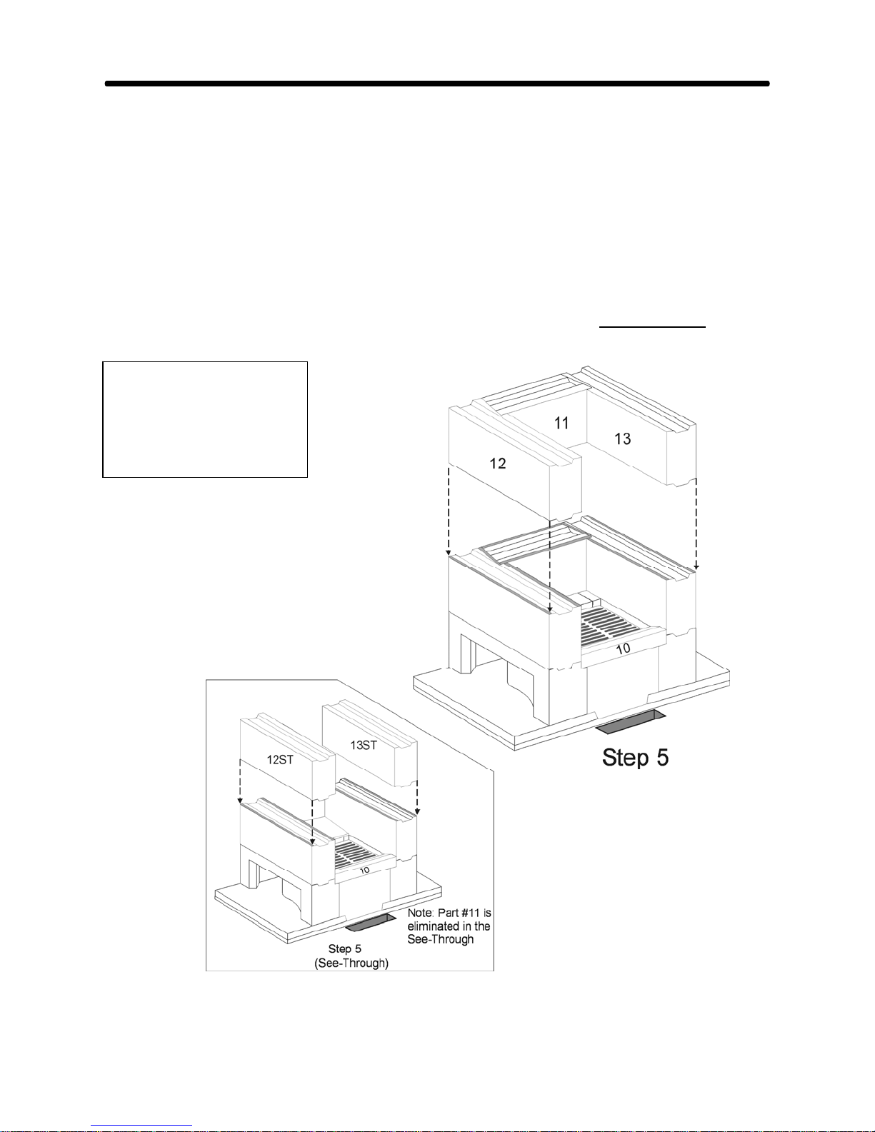
STEP 5:
Install Parts# 10, 11, 12 &13, using refractory mortar. Also “butter” the ends of part #10, so there
are no gaps on the ends. (Note that parts 11 thru 13 are identical to the previous course.) (In the
"See-Through" fireplace, there is no part #11.)
Seat with the rubber mallet and ensure that joints are tight.
Remember to keep the front edges of the modules aligned and use a 48” level to ensure that the
four sides are plumb.
Leveling the courses is not critical – it is sufficient if the courses are approximately level.
Weights
#10 - 12 lbs
#11 - 52 lbs
#12 & #13 - 68 lbs
#12ST & #13ST - 68 lbs
Temp-Cast 2000 Installation Manual
Page 16
Section 3 - Step-By-Step Assembly
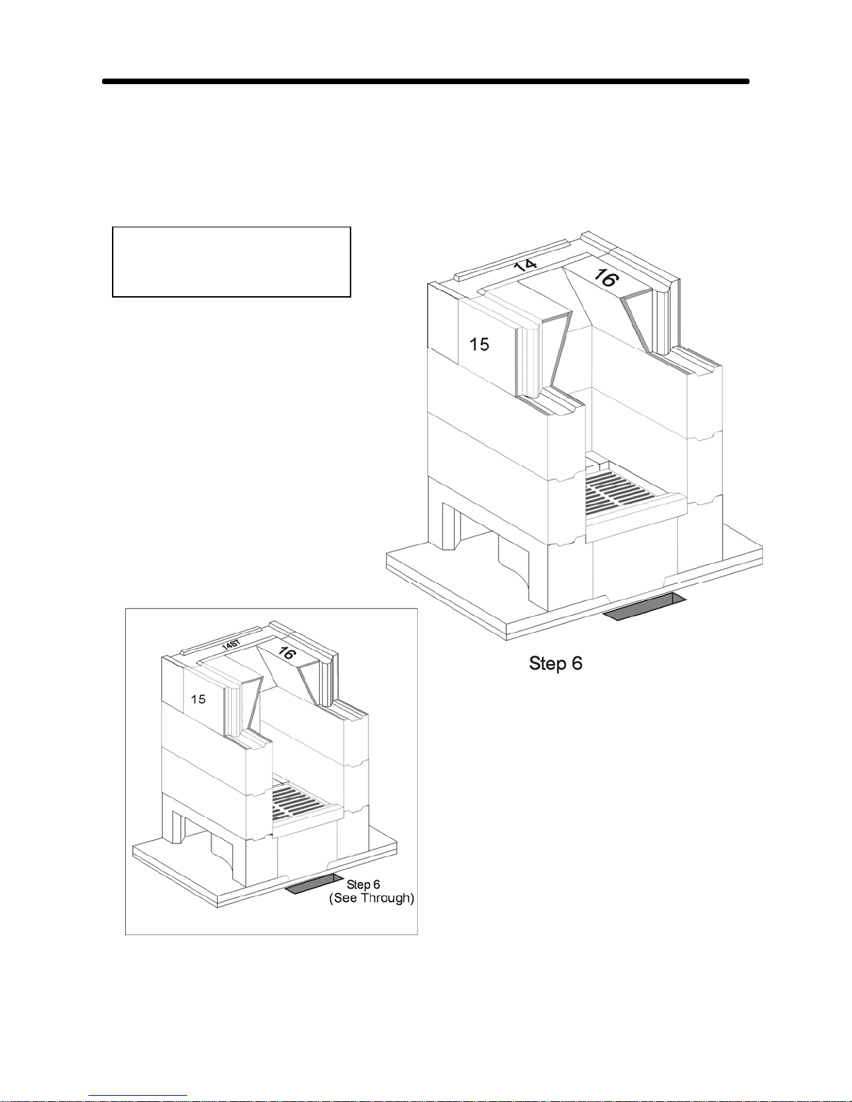
STEP 6:
Install the lintel course, parts 14, 15 & 16, in order, using a small (3/8”) bead of refractory mortar
on the outside edges of the adjoining parts.
Weights
#14 & #14 ST- 86 lbs
#15 & #16 - 64 lbs
16
Temp-Cast 2000 Installation Manual
Page 17
Section 3 - Step-By-Step Assembly
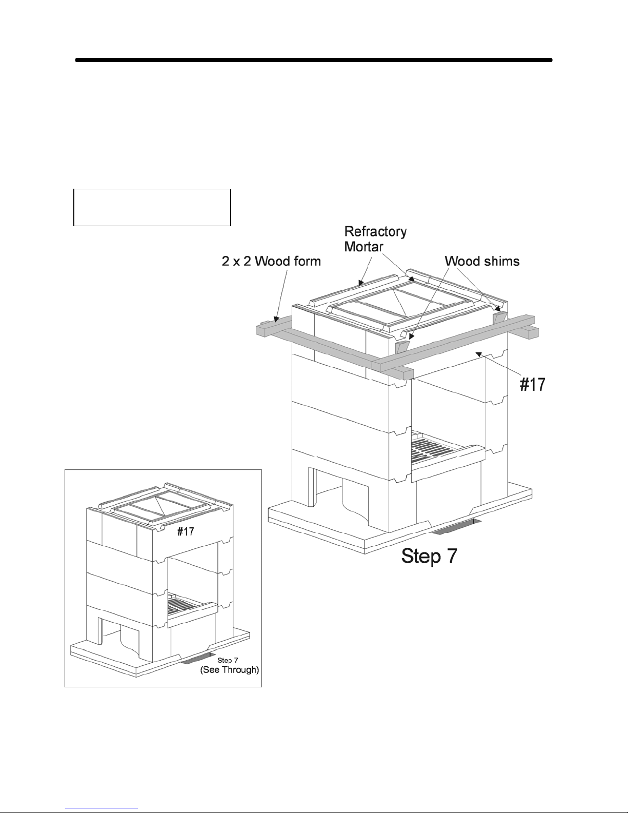
STEP 7:
Complete the lintel course with part # 17. Ensure that it aligns with the front edges of the
previous course. Seat firmly with the rubber mallet to ensure thin, strong joints and stable
support for the next course.
(If necessary, this course can be clamped with a tie-down until the refractory mortar sets.)
Weights
#17 - 84 lbs
17
Temp-Cast 2000 Installation Manual
Page 18
Section 3 - Step-By-Step Assembly
18
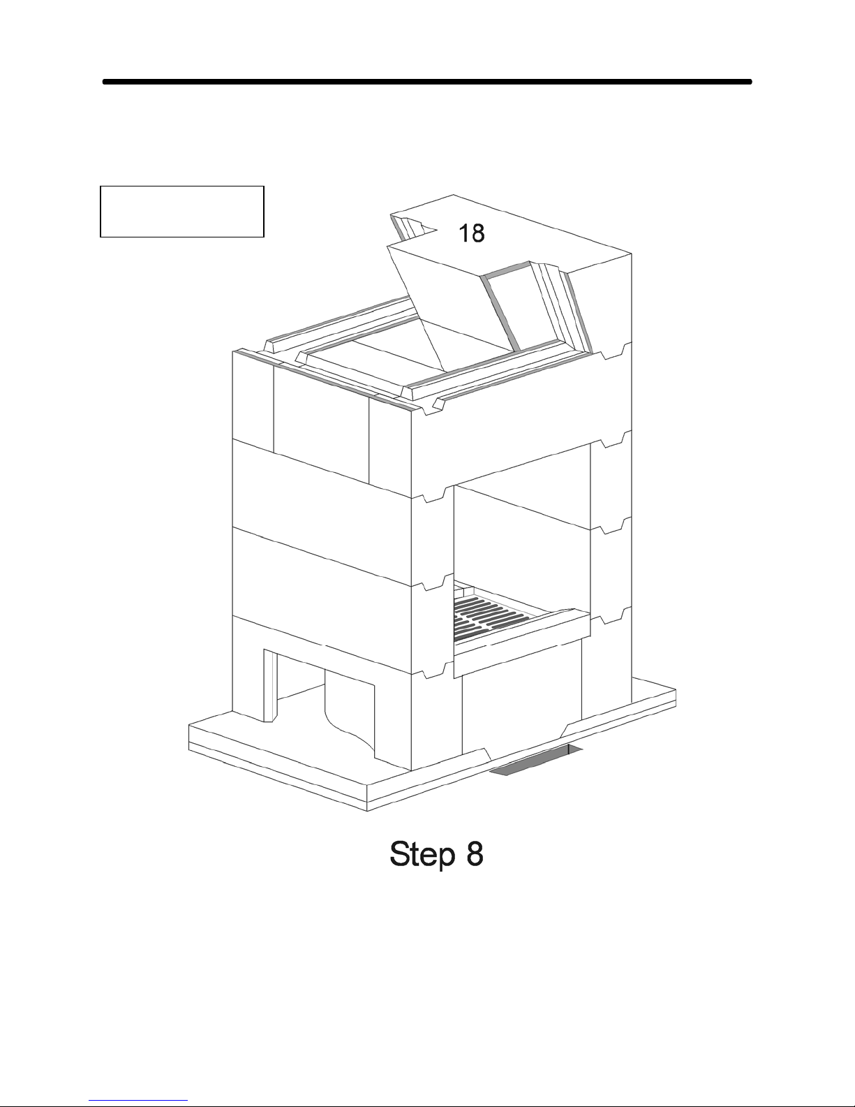
STEP 8:
This is the “smoke throat” course and begins with module #18. This part is heavy and awkwardly
shaped and usually requires 2 persons.
Weights
#18 - 93 lbs
Temp-Cast 2000 Installation Manual
Page 19
Section 3 - Step-By-Step Assembly 19
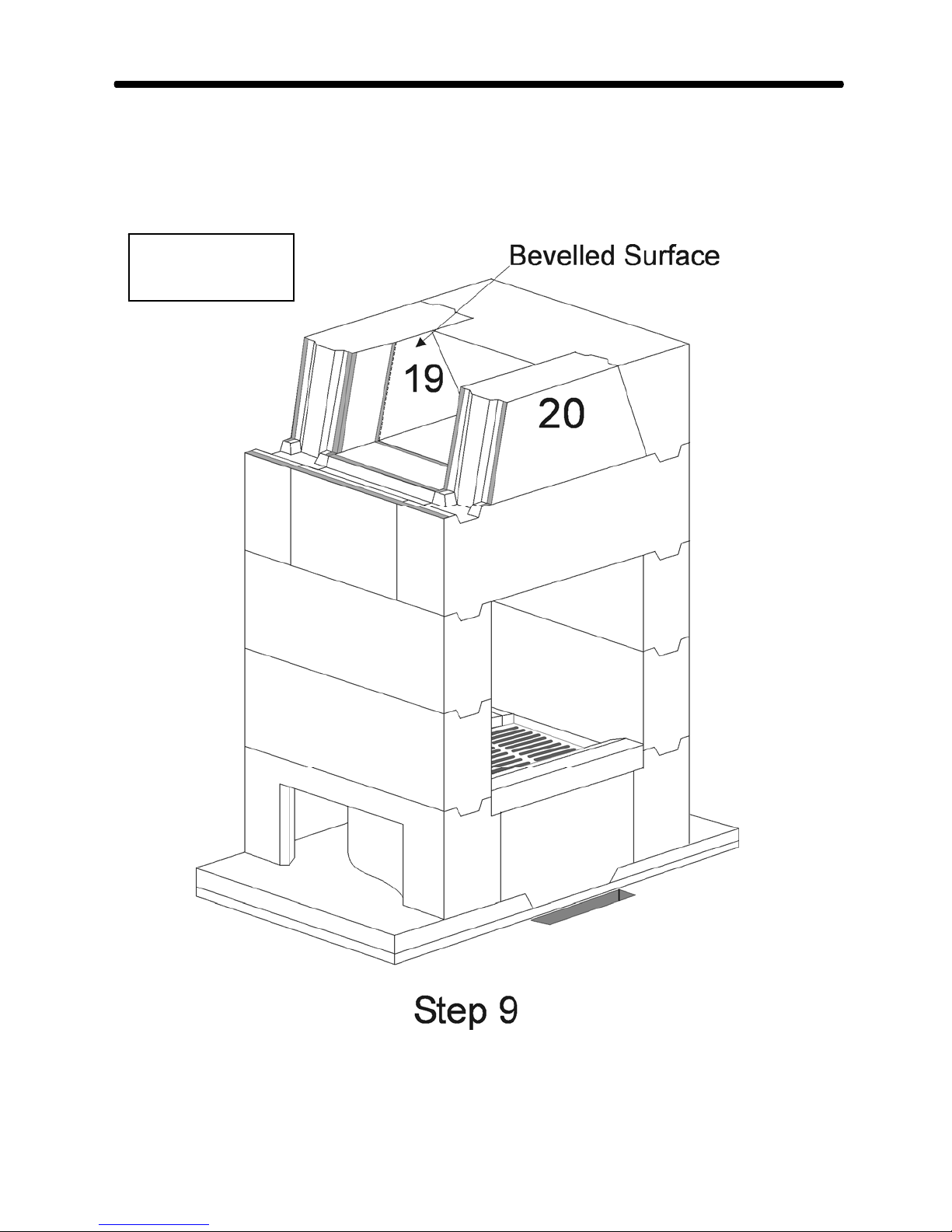
STEP 9:
Continue the smoke throat course with parts 19 & 20. (Note that the slightly beveled surfaces of
these modules face in towards the firebox.)
Weights
#19 & 20 - 35 lbs
Temp-Cast 2000 Installation Manual
Page 20
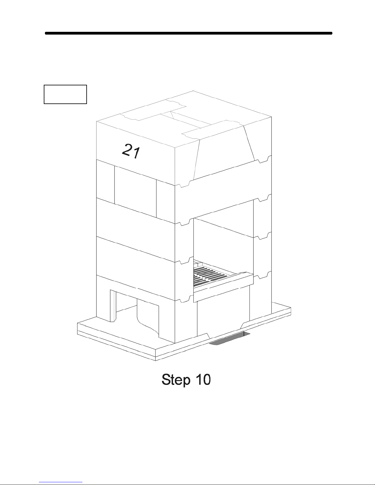
Section 3 - Step-By-Step Assembly 20
STEP 10:
Complete the smoke-throat course by installing #21. Remove all excess mortar and wipe the
modules inside and out.
Weights
#21 - 93 lbs
Temp-Cast 2000 Installation Manual
Page 21
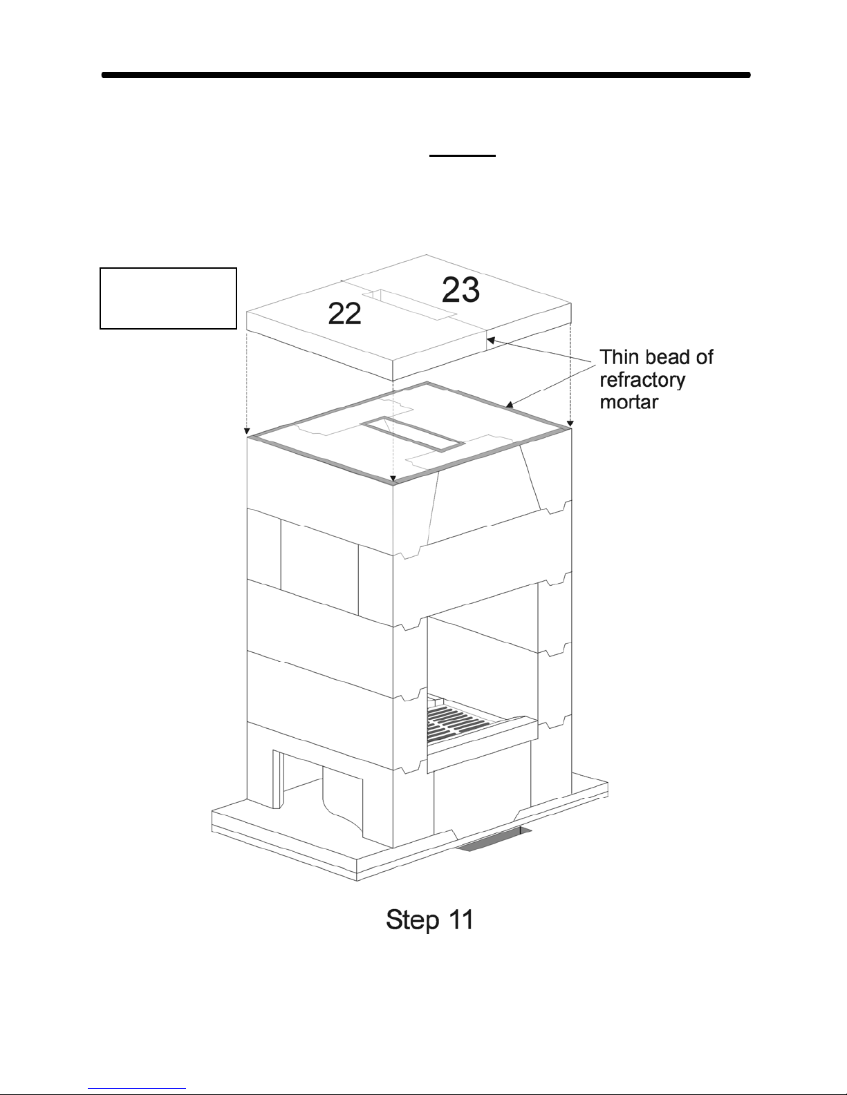
Section 3 - Step-By-Step Assembly 21
STEP 11:
These 2 parts, #22 & 23, form the floor of the secondary combustion chamber. They are not
keyed and are simply mortared in position with a thin bead of refractory mortar, around the
edges and between the 2 parts. (If this installation includes a Bake Oven, these parts and
subsequent courses are detailed on page 26.)
Tap firmly into place with the rubber mallet, to create as thin a joint as possible.
Weights
#22 & 23 - 40 lbs
Temp-Cast 2000 Installation Manual
Page 22
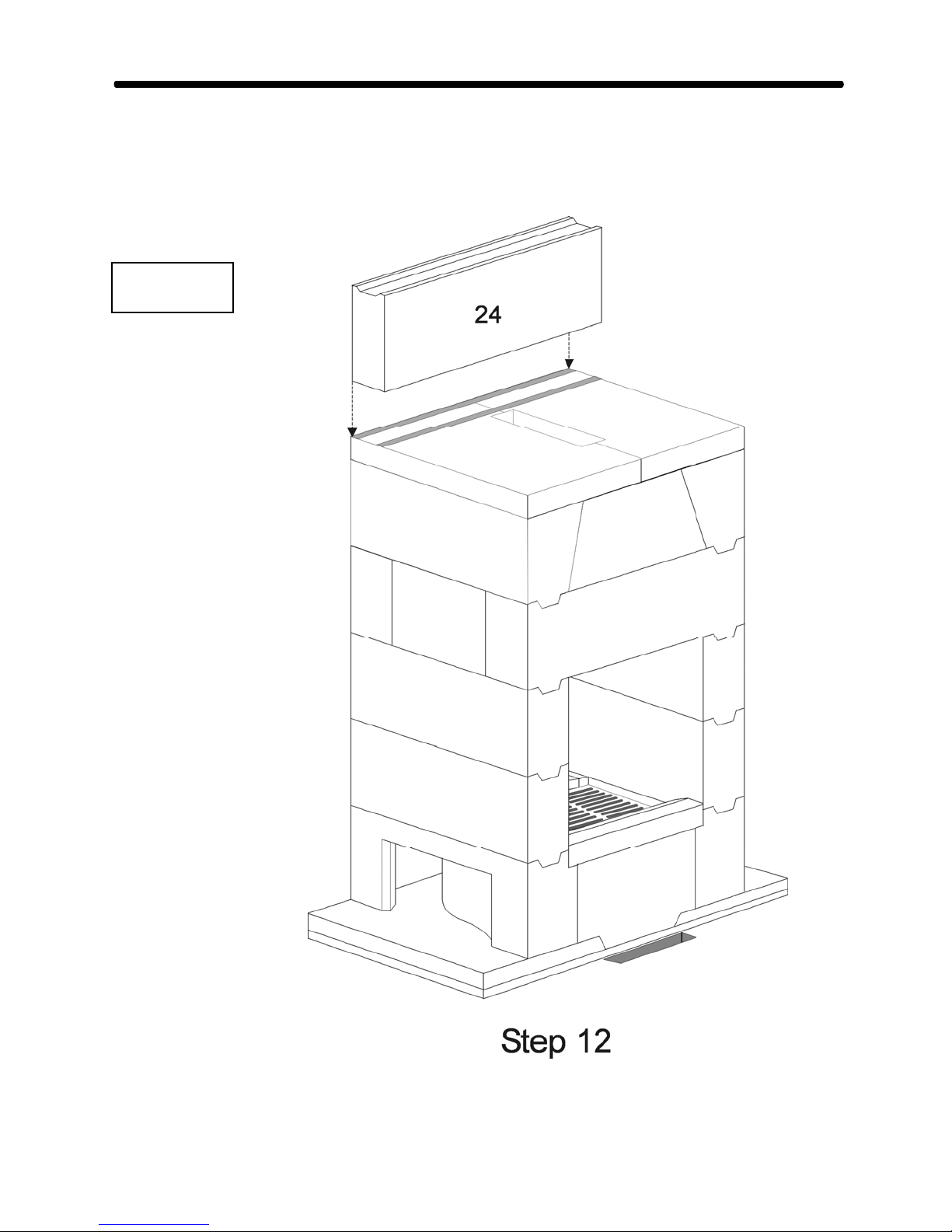
Section 3 - Step-By-Step Assembly 22
STEP 12:
Mortar and place the lower rear wall of the secondary combustion chamber, part #24. (Note that
the bottom edges of the parts on this course are not keyed.)
Weights
#24 - 66 lbs
Temp-Cast 2000 Installation Manual
Page 23
Section 3 - Step-By-Step Assembly 23
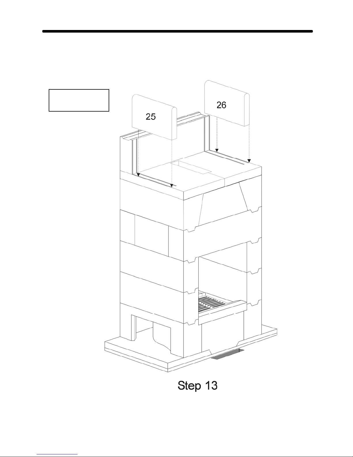
STEP 13:
Install the 2 short side walls of the secondary combustion chamber, parts 25 & 26. These parts
are not keyed and must be checked periodically to ensure they don't get out of position while the
refractory is drying.
Weights
#25 & 26 - 36 lbs
Temp-Cast 2000 Installation Manual
Page 24
Section 3 - Step-By-Step Assembly 24
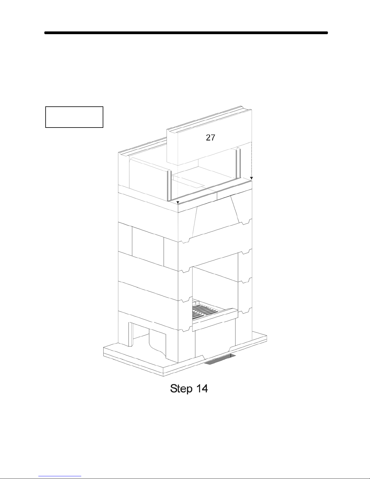
STEP 14:
Install the lower front wall of the secondary combustion chamber, part # 27.
Seat this part with the mallet & double-check the position of the side walls - adjust with the
rubber mallet as required.
Weights
#27 - 66 lbs
Temp-Cast 2000 Installation Manual
Page 25
Section 3 - Step-By-Step Assembly 25
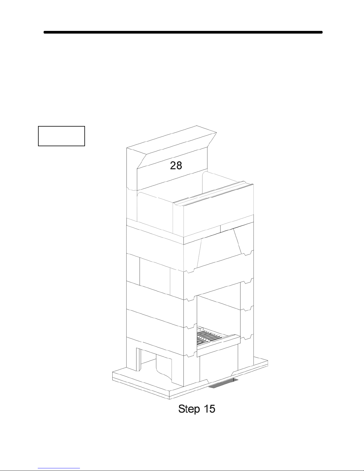
STEP 15:
Install part #28, the upper rear secondary combustion wall.
This is also a heavy part and may require 2 people, so that the previous course does get
disturbed. Installation is easiest if the bottom of the module is placed first into position and then
raised upright. So this part does not tilt inwards, a little extra refractory mortar can be used on
the inside edge of the part.
Weights
#28 - 126 lbs
Temp-Cast 2000 Installation Manual
Page 26
Section 3 - Step-By-Step Assembly 26
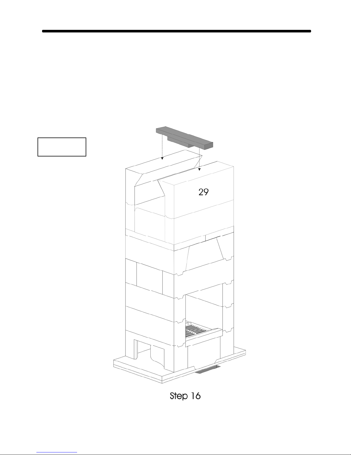
STEP 16:
Part #29 is installed to complete the secondary combustion chamber, forming the front wall.
These 2 upper walls may have a tendency to lean inward while the mortar is setting. Leaning
can be prevented by making a simple wood jig. Cut a length of 2x4, 11-7/8” long. This piece
will be the "spacer".
Nail this piece to a longer piece of wood. Place the jig on top of the walls, so that the spacer
hangs down and prevents the two walls from leaning inward. (This jig can be left in place until
Step 20.)
Weights
#29 - 126 lbs
Temp-Cast 2000 Installation Manual
Page 27
Section 3 - Step-By-Step Assembly 27
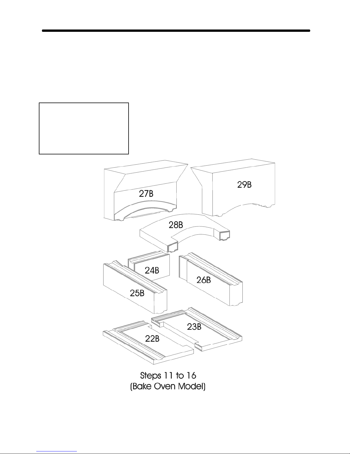
STEPS 11 THRU 16: (Bake Oven Installation)
Assemble the Bake Oven parts, in numerical order, as illustrated below. Parts 22B and 23B are
laid with a bead of refractory mortar around the outside edges of the parts and seated with the
rubber mallet. Use refractory mortar wherever one part joins another, as indicated by shaded
areas. (Remember to immediately remove excess mortar and clean the inside with a damp
sponge.)
#22B, #23B & #24B - 48 lbs
Weights
#25B &26B - 51 lbs
#27B - 126 lbs
#28B -100 lbs
#29B - 114 lbs
Temp-Cast 2000 Installation Manual
Page 28
Section 3 - Step-By-Step Assembly 28
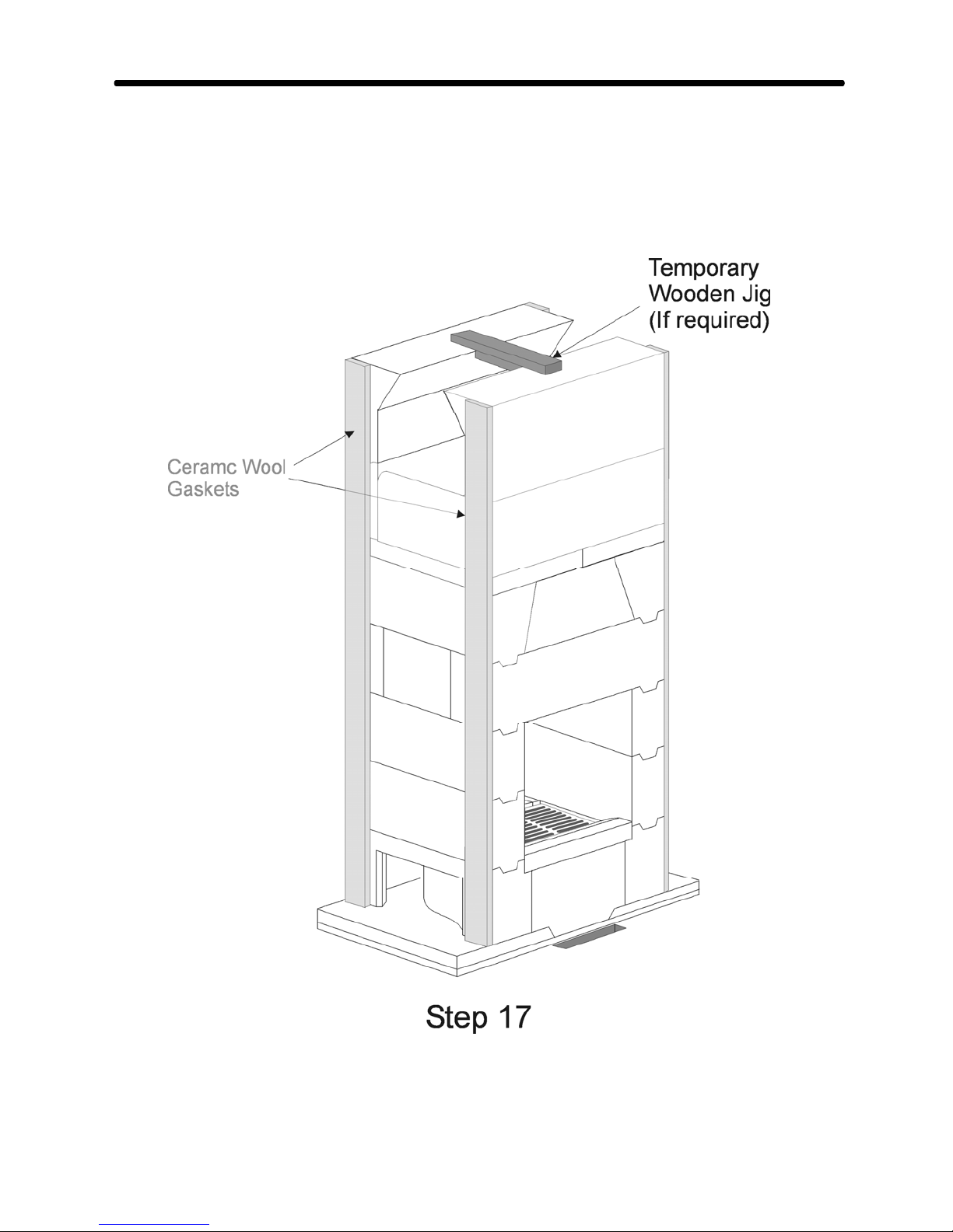
STEP 17:
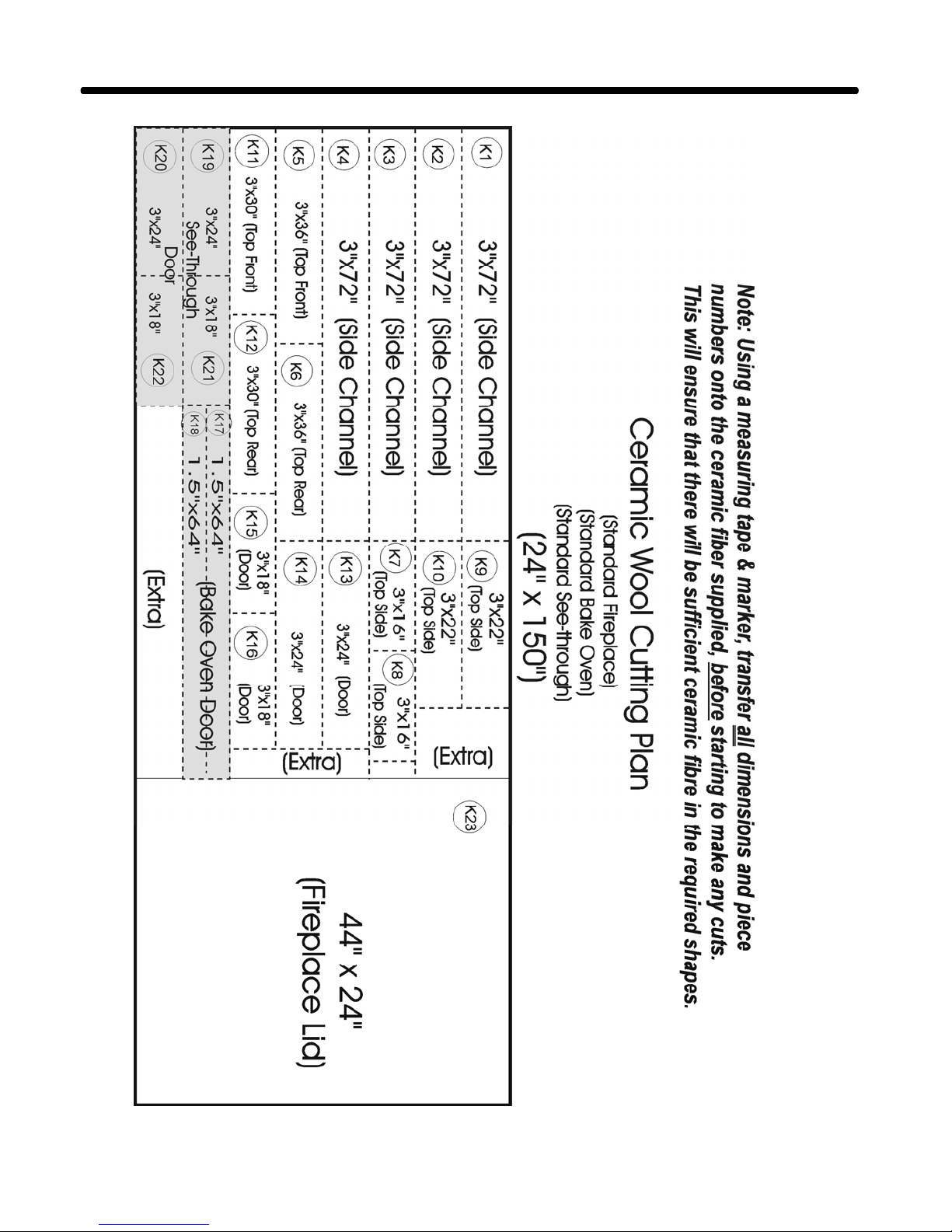
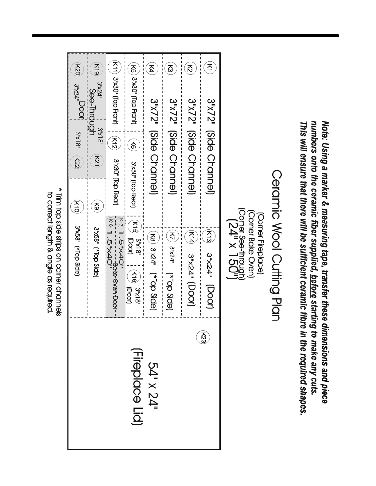
Find the ceramic fibre "Cutting Plan" in Section 6 for the model you are installing. With a tape
measure, magic marker & straight-edge, transfer the "Cutting Plan" dimensions & piece numbers
to the ceramic fibre. Cut out the four (4) strips marked "3"x72" (Side Channels)" K1 thru K4,
and glue them to the exterior of the core as shown below, using five or six evenly spaced small
dabs of refractory mortar.
Temp-Cast 2000 Installation Manual
Page 29
Section 3 - Step-By-Step Assembly 29
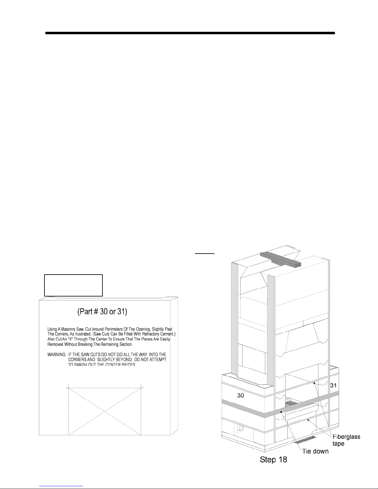
STEP 18:
If the flue connection is on the side of the fireplace, the hole for the flue connector is cut at this
point, as shown. (See below for important suggested cutting technique.) (Refer also to Fig. #3 &
#4.) (For a Corner Fireplace, see page 31, for Steps 18 to 20.)
Dry assemble the lower heat exchange channels, #30 & 31, and mark the location of the flue
hole. The hole in the heat exchange channel should be cut as tightly as possible, up to about 1/4"
larger all around than the flue tile.
In addition, cut a 6" x 6" hole in the opposite heat exchange channel, on the non-chimney side,
for a soot cleanout door. Align this hole with the centre of the cross manifold, part # 3. (If a
rear chimney connection has been made, the second soot door may be installed on the opposite
side channel, to simplify inspection and cleaning from both sides. Both soot doors should align
with the centre of the cross manifold. A third cleanout door will be needed for the base of the
chimney.)
The transition from fireplace to flue connector should be as smooth and rounded as possible, so
that the smoke does not encounter any corners or ledges as it enters the flue connector. (Refer to
Fig. 8.)
Ensure that the ceramic fibre strips have been applied to the core walls. Now position the first 2
heat exchange channels, using refractory mortar on their bottom edges only.
Use a “tie-down” or web clamp around the 2 channels to slightly
compress the ceramic fibre. Secure the channels with 2 bands of
packing tape, then remove the tie-down.
Weights
#30 & 31 - 95 lbs
Temp-Cast 2000 Installation Manual
Page 30
Section 3 - Step-By-Step Assembly 30
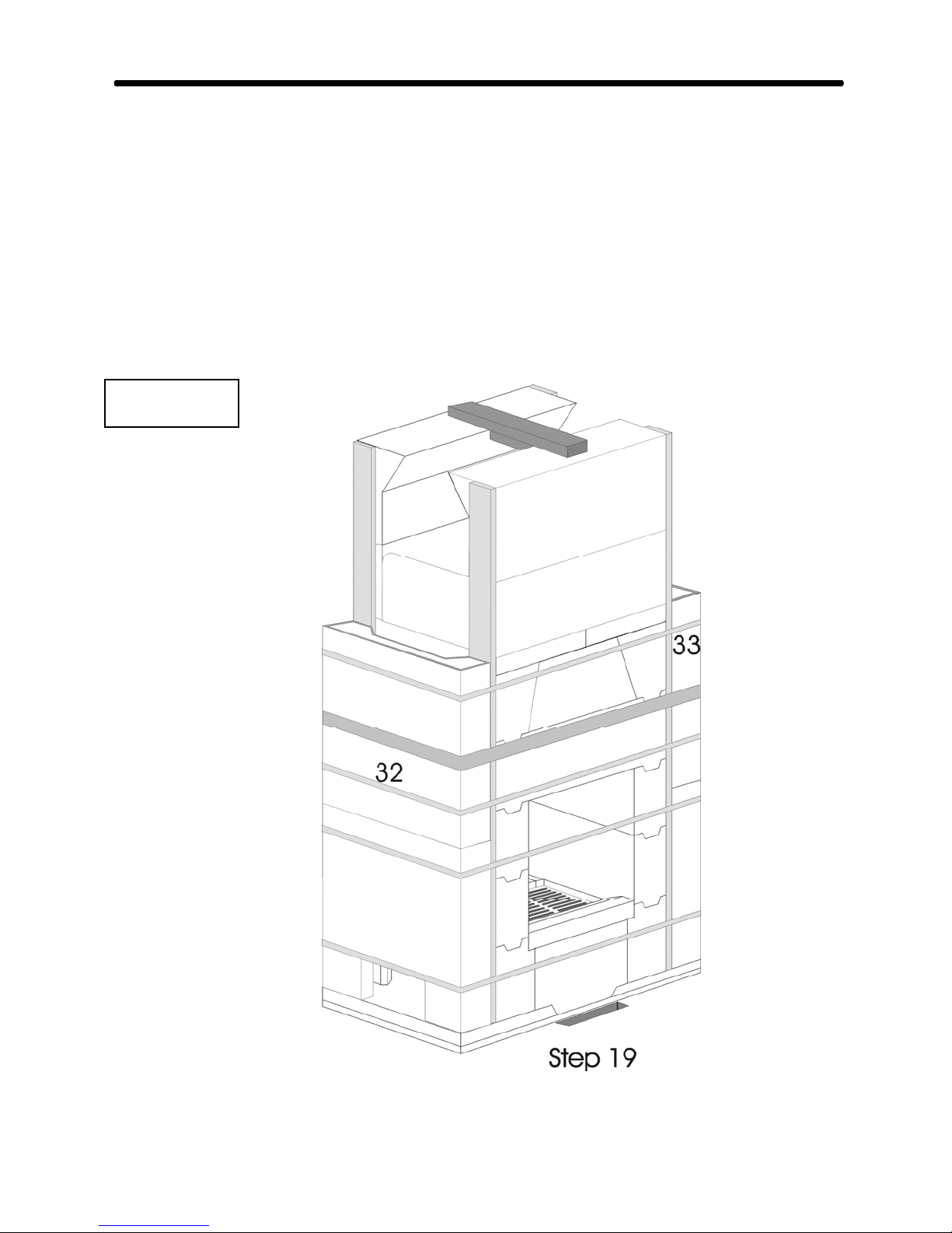
STEP 19:
Set the middle heat exchange channels (#s 32 & 33) in place, using a thin joint of refractory
mortar between channels. (If mortar squeezes out on the inside surface of the heat exchange
channels, wipe if off. Keeping the mortar back from the inside edges will prevent having to
reach in to wipe off excess mortar from this area.)
Slightly compress the ceramic fibre using the tie-down and secure these two channels with 2
bands of packing tape, as illustrated. (The packing tape can be left in position when the facing is
being applied and then any visible tape can be cut out.)
Weights
#32 & 33 - 95
Temp-Cast 2000 Installation Manual
Page 31
Section 3 - Step-By-Step Assembly 31
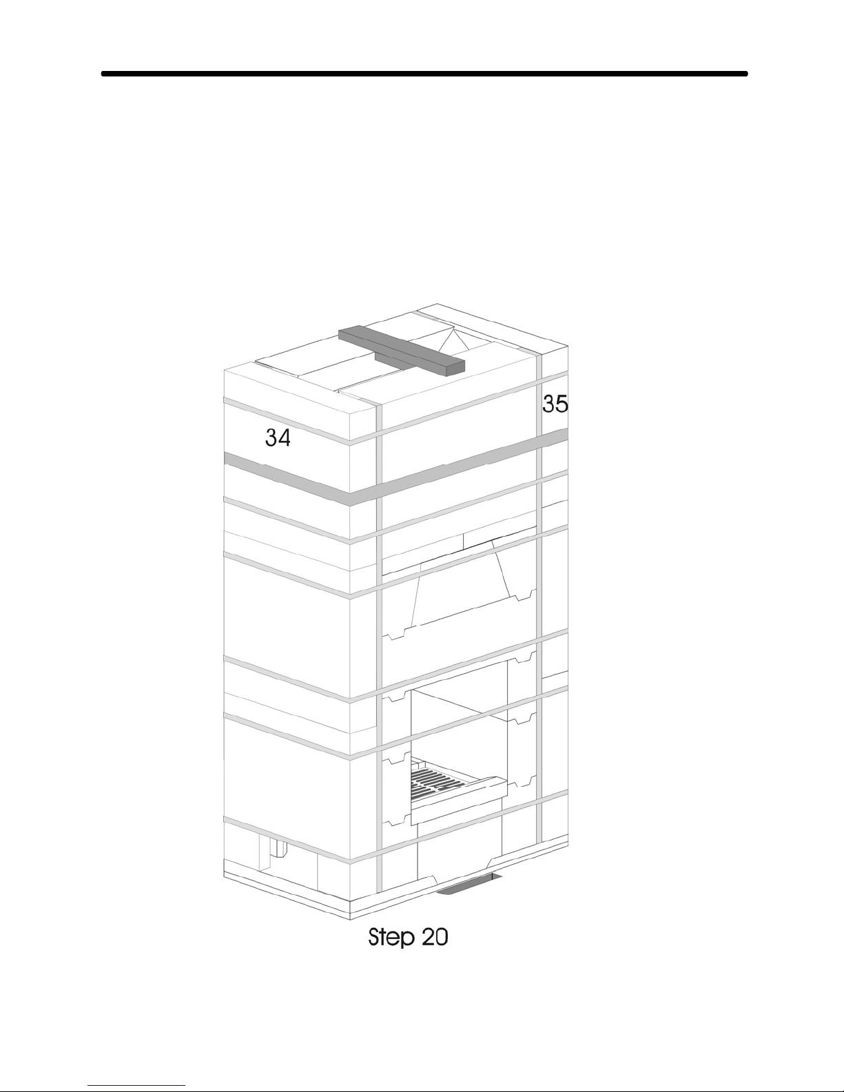
STEP 20:
Install the upper heat exchange channels, #34 & 35. Note that these are slightly different than
the other 4, with a transition formed on the inside upper surfaces, and an enclosed top.
Use a thin refractory mortar joint between these and the previous channels and secure these parts
with the tie down and packing tape. (Remove the temporary wood support jig.)
Temp-Cast 2000 Installation Manual
Page 32
Section 3 - Step-By-Step Assembly 32
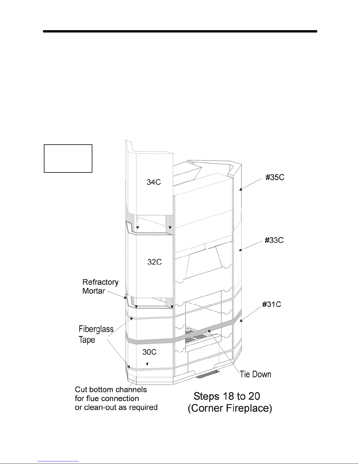
STEPS 18 THU 20: (Corner Fireplace)
If the chimney connection is to be made in the side of the fireplace, dry assemble the first corner
channel and mark the location of the flue hole on the designated surface. Mark a location for a
clean-out (soot) door on the opposite channel. Cut these holes in the outdoors.
Re-assemble the first two corner channels, using a little refractory on their bottom edges. Use a
tie down and 2 bands of packing tape or fiberglass-reinforced tape around each pair of channels so they do not fall during the next few steps.
Continue with the other four corner channels, using refractory mortar between them. Secure
each pair of channels with 2 bands of packing tape or fiberglass re-enforced tape as they are
installed.
Weights
#30C to 35C
130 lbs
Temp-Cast 2000 Installation Manual
Page 33
Section 3 - Step-By-Step Assembly 33
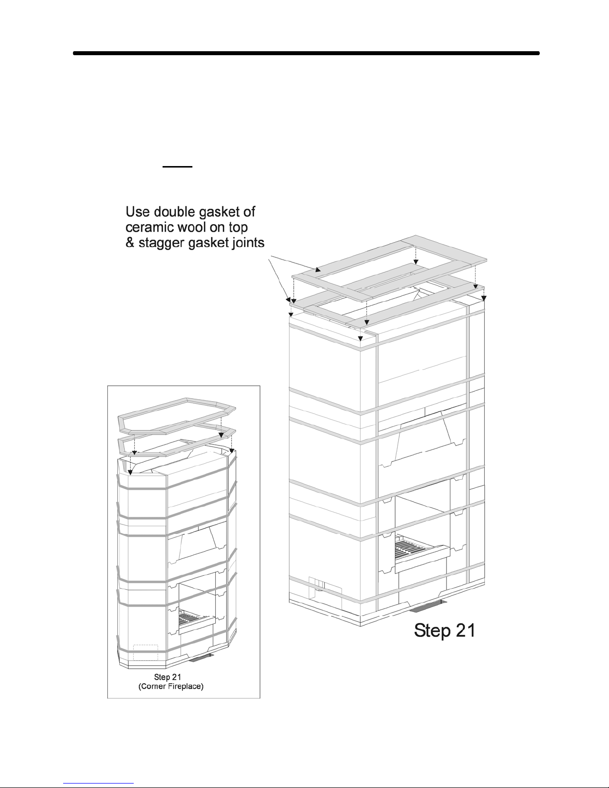
STEP 21:
Install a gasket of strips of ceramic wool to the top of the fireplace, as illustrated below. (A few
spaced dabs of refractory mortar can be used to keep gaskets in place.)
On bake oven models, an extra strip should be installed front and rear to bring the center up to
the same level as the top of the side channels (see note below). Install the remaining strips, as
illustrated, using a small dab of refractory mortar to hold them in place. Trim the strips as
required for a snug fit. (Corner fireplace gaskets are placed with the same over-lapping principle
in mind.)
Temp-Cast 2000 Installation Manual
Page 34
Section 3 - Step-By-Step Assembly 34
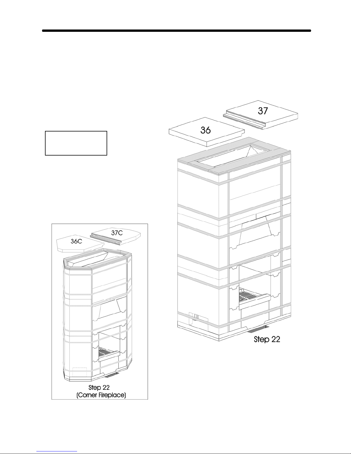
STEP 22:
Place the two halves of the fireplace lid on top, using a refractory mortar between them. (The
smoothest side should be placed down - the parts are interchangeable left to right.) Note that
no mortar is used between the lid and the ceramic gasket.
Since the lid is slightly smaller than the top of the fireplace, an equal amount of space should be
left all around.
Weights
#36 & 37 - 80 lbs
#36C & 37C -95
Temp-Cast 2000 Installation Manual
Page 35
Section 3 - Step-By-Step Assembly 35
STEP 23:
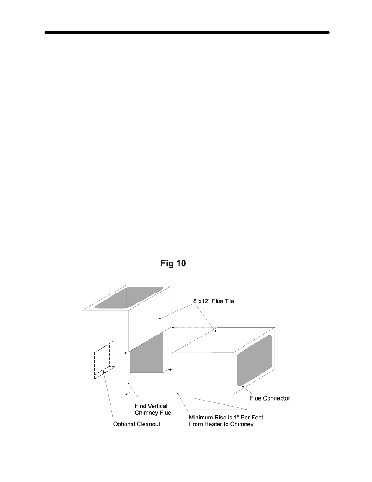
Cut the flue connector to the correct length and with the correct angle, so that it rises up 1"/ft
(25mm/300mm) towards the chimney.
Install the flue connector with refractory mortar to the heat exchange channel and support it in
the correct position.
NOTE: extra care must be taken to be certain that the flue connector does not go beyond the
inner surface of the heat exchange channel. Ideally, the connector should penetrate the heat
exchange channel no more than one inch (25mm). (Refer also to Fig.3.)
Reach inside the flue connector to smooth and round the corners of the connection. Remove
excess refractory mortar from the inside edges of the flue connector.
Cut the first vertical flue tile, as shown in Figure # 10. Note that the chimney cleanout is shown
in the preferred position - in-line with the flue connector. If this alignment is not possible, the
cleanout can be on either of the other 2 available sides. (If a chimney clean-out is planned for a
lower level, a soot door should still be installed at the flue connection level, for inspection and
removal of fly ash which will accumulate at the bottom of the heat exchange channels.)
Wrap the flue connector and the first vertical flue tile with extra ceramic wool, "coreflex" or
cardboard spacer and mortar them solidly in position with common mortar.
ALL JOINTS MUST BE SEALED WITH REFRACTORY MORTAR TO BE SMOKE
TIGHT.
Temp-Cast 2000 Installation Manual
Page 36
Section 3 - Step-By-Step Assembly 36
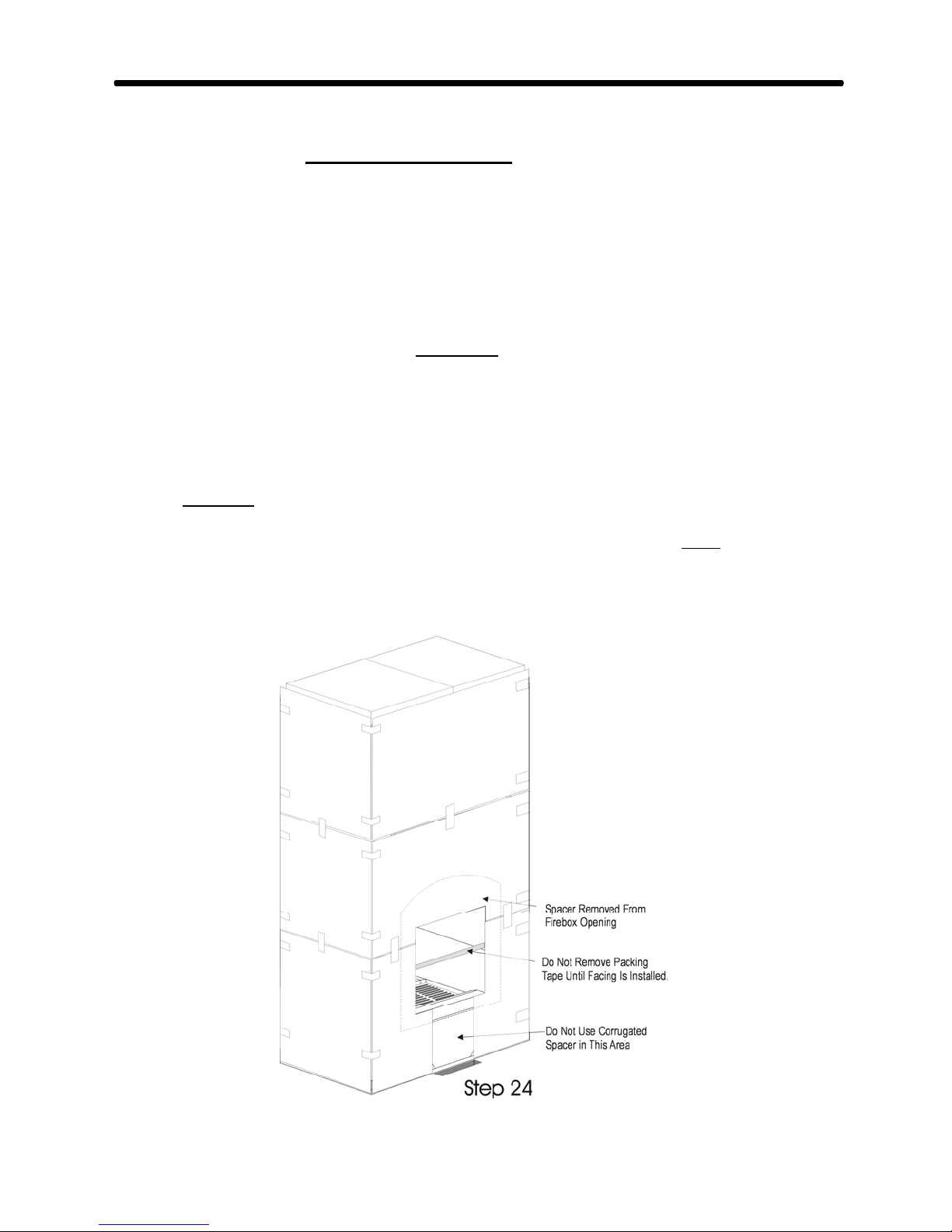
STEP 24:
Remove the “tie-downs”, but leave the tape in place. The heater now needs to be completely
wrapped with the corrugated spacer supplied, but openings for fire-doors, bake-ovens, air doors
and cleanouts may have to be pre-cut, so that the packing tape is not inadvertently cut.
To pre-cut the opening for the firebox, lay 2 pieces of corrugated spacer on the floor, with their
longest sides butting. Measure up from the bottom of the spacer 13½" and draw a horizontal line
across the spacer. Measure over 6" from either side edge and draw a vertical line at this point.
Remove the door from the frame and place the frame on the spacer, using the two lines drawn to
position the bottom and left edges of the frame. Trace around the entire frame and then remove
the frame. Cut the spacer approximately ½" larger than the traced line on all sides & remove
the piece.
Place these 2 cut pieces on the front of the heater, starting at the bottom. Continue with other
pieces of corrugated spacer around the heater, but pre-cut any holes for cleanouts, air doors,
bake-ovens etc using the same technique as the firebox doors, to prevent cutting the packing
tape. (When installing the cardboard on the back side, it may be helpful to cut the cardboard
vertically part-way through where it covers the ends of the side channels – this will help to
prevent any air gaps from being created in these areas.) Tape the spacer in place. (For corner
units, a flexible “coreflex” spacer is supplied. Wrap this around the heater twice to get the
correct thickness.)
Also cut out a section of spacer in the area of the air intake slot, directly under the firebox, as
illustrated.
Temp-Cast 2000 Installation Manual
Page 37
Section 4 – Installation of Door Frames & Facades
37
SECTION 4: DOOR FRAMES & FACADE
THE DOOR FRAME FLANGE:
The Temp-Cast “arched” door system was
designed so that a standard brick, with a
nominal thickness of 3.75”, could be easily
installed behind the door flange. However,
since brick sizes vary greatly across North
America, masons often cannot find a
suitable brick in these dimensions. In
addition, natural stone and rock often cannot
be found in these dimensions.
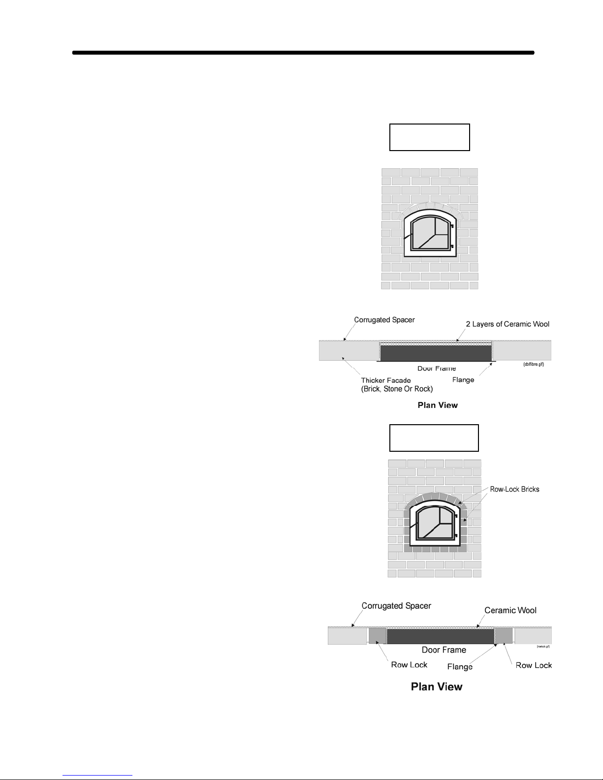
FACADE/ FLANGE OPTIONS:
The following techniques will allow thicker
facades to be concealed behind the door
flange.
FOR FACADES UP TO 4.25” THICK:
Glue an extra layer of 1/2” ceramic fibre
between the door frame and the heater core,
on top of the standard 1/2” layer. When
slightly compressed, this extra layer will
provide up to 3/8” additional space behind
the door flange. (Refer to Fig. 11)
FOR FACADES OVER 4.25” THICK:
For facades more than 4.25” thick, a “rowlock” bond can be employed, in which halfbricks are cut to approx. 3” and laid around
the door frame, fitted behind the flange.
Thicker facade materials can then be laid up
next to these row-lock bricks. (See Fig.
11a)
Alternatively, attach fire-brick “splits”
around the door frame opening with
refractory mortar, before the ceramic wool is
applied. These splits, up to 1.5” thick,
increase the space between the core and the
flange, allowing for a thicker facade material
to fit behind it. (In all cases, increase the
combustion air space under the door by the
thickness of the added splits - e.g. cut an extra
1.5” from the facing under the door if 1.5” splits
are added.)
FIG. 11
FIG. 11A
Temp-Cast 2000 Installation Manual
Page 38
Section 4 – Installation of Door Frames & Facades
38
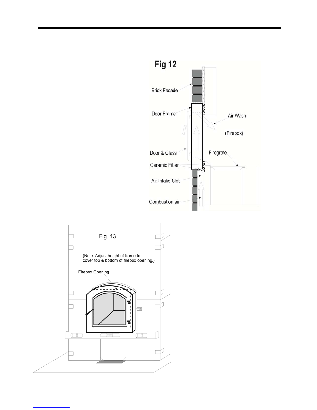
INSTALLING ARCHED FIRE DOORS
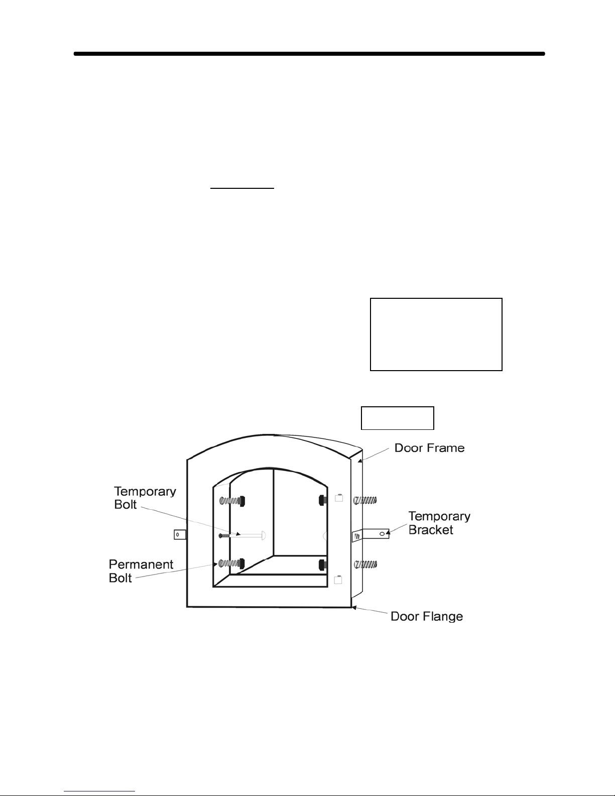
Although experienced masons may use a
different technique to attach the arched door
frame, the following method ensures two
critical points:
The finished door frame MUST NOT be
permanently attached directly to the
core. This will ensure that the frame is
isolated from the thermal expansion of
the refractory. (See Fig. 11b)
Air slots in the bottom of the frame and
(Note: rear doors on a See-Through
Fireplace are positioned slightly higher
than the front doors - about 1.5". Refer to
Fig. 16)
The door frame position can be adjusted up
or down slightly to accommodate the facade,
so that the frame will sit on top of a masonry
or stone course. However, ensure that the
door frame still covers the firebox
opening, particularly on the top, in the
case of an arched frame. (See Fig. 13)
in the concrete floor pad are properly
aligned & unobstructed, as in Fig. 12.
ARCHED FIRE DOORS - Step One
Remove the doors from the frame and set
them aside. Position the door frame on the
core so that the slope of the bottom inside
To keep the door clean, it
can be removed from the
frame and installed when
the facing is completed.
edge of the frame (i.e. the "sill" of the door
frame) and the slope of module # 10 form a
nearly continuous angle, as in Fig. 12.
Level the frame and make a pencil mark on
the cardboard spacer along its bottom edge.
Fig 11b
Temp-Cast 2000 Installation Manual
Page 39
Section 4 – Installation of Door Frames & Facades
39
Temp-Cast 2000 Installation Manual
Page 40
Section 4 – Installation of Door Frames & Facades
40
ARCHED FIRE DOORS - Step Two
Build up the masonry facade to the bottom
of the firebox door, while maintaining a
2”x15” air slot under the door. Adjust the
height of the door frame as needed to suit
the masonry courses, ensuring the frame still
covers the firebox opening. Trace the frame
on the cardboard spacer.
Using a small amount of refractory mortar,
glue a 3" wide strip of ceramic wool to the
face of the core where the cardboard was
removed. (e.g. Pieces K13 thru K15 on the
ceramic wool cutting plan). Also glue a
strip of ceramic fiber on the top of the last
masonry course, ensuring that the air slot in
the bottom of the door frame is not
obstructed.
Place the door frame in position & brace it
firmly with a length of 2x4 wedged under
the one of the hinges & nailed to the floor.
A second 2x4 can be braced under the upper
door opening. (Alternately, the frame is
fitted with 2 small brackets, which can be
used to temporarily secure the frame to the
core with the “tap-con” screws supplied.)
NOTE: ensure that the ceramic gasket is
slightly compressed, but not crushed.
WARNING!
It is important that the ceramic fibre be
Cover the door frame to keep it clean for the
rest of the installation. Continue to Step 3.
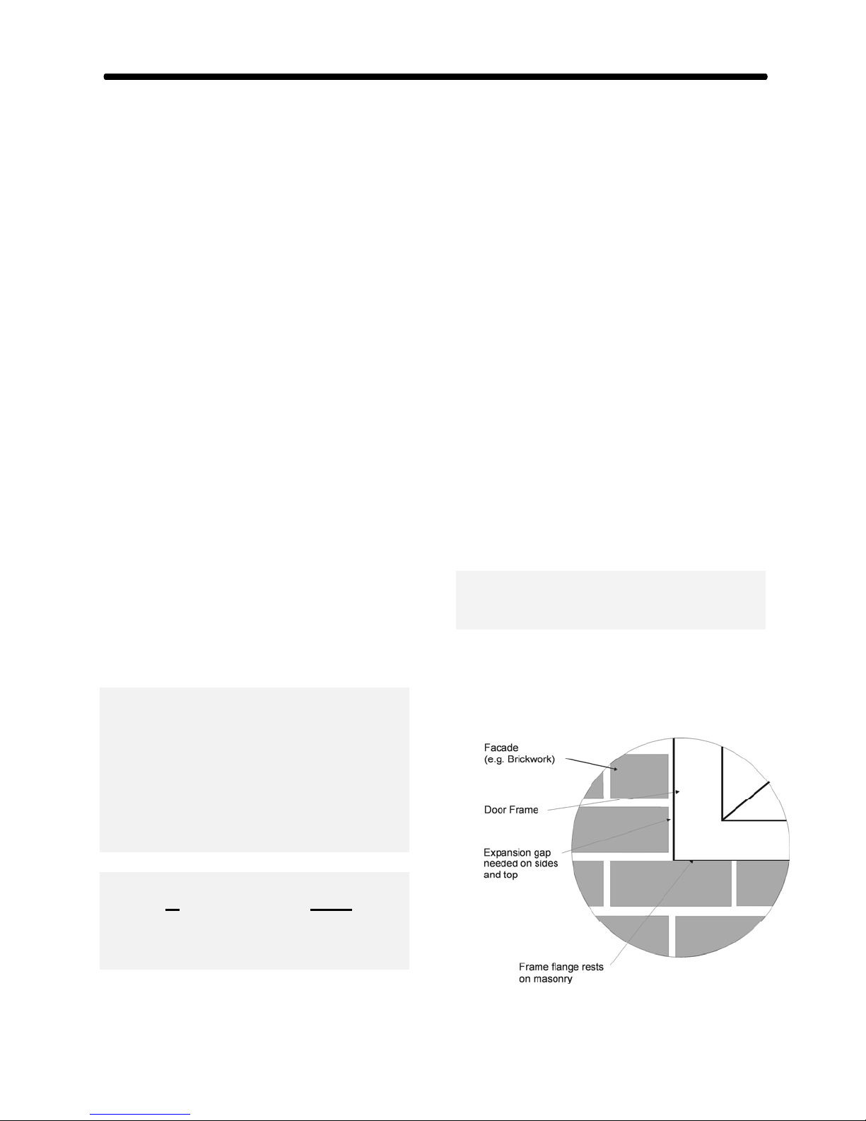
IF THE FLANGE WILL NOT COVER
THE FACADE:
If the masonry facade will not be hidden
behind the door flange, care must be taken
to ensure that an expansion gap is created
between facade and door frame.
Glue a 3" strip of ceramic wool (pcs K13
thru K15) onto the core where the cardboard
was just removed. Also place one or two
strips of ceramic wool fiber on top of the
masonry course, so that air cannot leak into
the fire box from under the door frame.
Care must be taken to ensure the air slots
in the bottom of the door frame are not
obstructed. Place the door frame in
position & bolt it or brace it with 2x4s. The
bottom flange of the door frame rests on the
masonry.
(Note: do not remove the factory-installed
cardboard “coreflex” gasket from around the
door frame!)
Continue with Step 3. However, ensure that
an expansion gap of about 1/8" (3mm) is left
between the masonry and the side and top
flanges of the door frame. (See Fig. 14)
slightly compressed and glued in place, so
that it cannot fall out. This will ensure that
live embers cannot fall into the space
between the door and the heater core, or
into the air intake and create a potential fire
hazard.
No combustible materials should be
installed in the foundation or under the
foundation, due to the potential fire risk!
Fig 14
Temp-Cast 2000 Installation Manual
Page 41
Section 4 – Installation of Door Frames & Facades
41
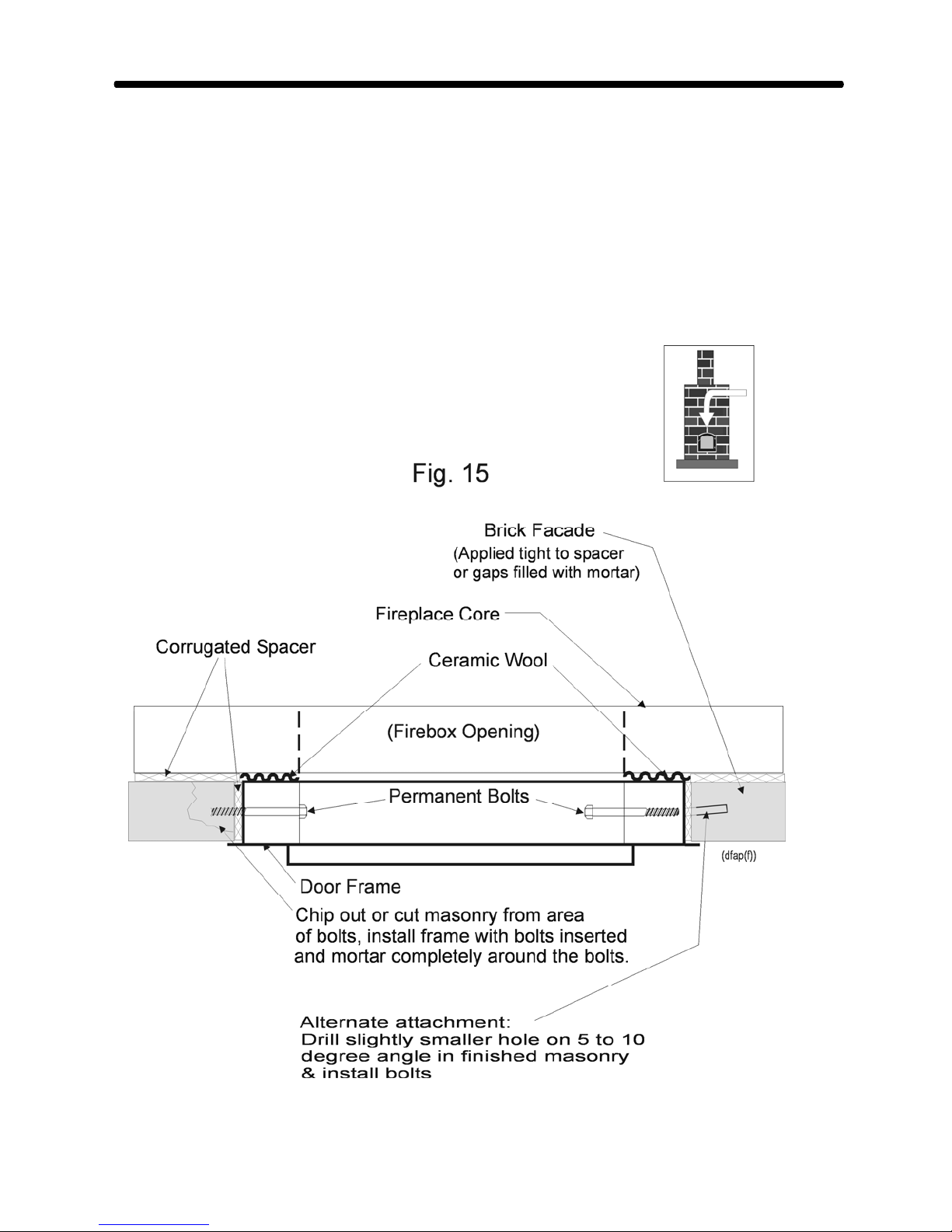
ARCHED FIRE DOORS - Step Three
Continue with the masonry facade, up to the
level of the first permanent bolt attachment.
Insert the four permanent bolts into the
frame.
Chip or cut the brick or other masonry, so
that a cavity is created around the area of the
bolt. (Refer to plan-view illustration, Fig.
15)
Continue raising the facade, filling the space
around the bolt with mortar, tight to the
"coreflex" spacer.
Temp-Cast 2000 Installation Manual
Page 42

Section 4 – Installation of Door Frames & Facades
42
ARCHED FIRE DOORS - Step Four
When the facade is complete and the
masonry has fully set, remove the 2
temporary bolts from the frame. (If the 2
small brackets were used, this will detach
the frame from them.) The door frame is
now independent of the fireplace core and
will not be affected by the thermal
expansion of the core.
Replace the doors on the frame and check
for proper fit and operation.
ceramic wool gasket. (Do not re-bolt the
frame to the temporary brackets.)
AIR SUPPLY DOORS
If an air supply door is to be installed, its
frame is installed in the facade when it
reaches the desired height. (See Fig. 1b).
The installer can use mortar, lead anchors or
"tap-con" screws to secure the door frame.
CLEAN-OUT DOORS
Similarly, clean-out (soot) door frames are
installed when the facade reaches the height
ALTERNATE ATTACHMENT METHOD
If cutting or chipping masonry around the
bolts is not possible, an alternate (but more
difficult) attachment method can be used.
(See Fig. 15.)
Remove the 4 permanent bolts from the
door frame. Build the facade around the
door frame (or around the flange, as the case
may be) and complete the masonry work.
When the masonry work is fully set, (i.e.
after 1 or 2 days) make a mark on the
masonry where the 4 bolts will go, using the
bolt holes as a guide. Care must be taken
at this point so that the threaded holes on
the outside of the frame are not damaged.
Now unbolt the frame from the 2 temporary
brackets and take the door frame out. (If the
"coreflex" spacer comes out with the frame,
of the clean-out holes in the heat exchange
channels. The soot doors should be located
on both sides of the heater, at the bottom of
both heat exchange channels, in line with the
cross-manifold, Part # 3.
When a side chimney connection is made,
one of the two clean-out doors should be
placed at the bottom of the chimney, so that
the bottom of the heat exchange channel on
that side can also be accessed from the same
door. In the case of a rear chimney
connection, a third clean-out door will be
required for the chimney itself. (Standard
chimney clean-outs are available at brick
supply yards or a third Temp-Cast clean-out
can be ordered.) Cover all door frames
immediately after installation to keep them
clean.
replace it before the frame is re-installed.)
Using a masonry drill of the same thickness
as the permanent bolts, drill holes into the
masonry at the marks made earlier. These
holes should be at least 1" (25mm) deep and
on a slight angle (about 5 degrees) towards
the firebox. (Fig. 15)
Re-install the door frame and attach with the
four permanent bolts - the slightly angled
holes will draw the frame tight to the
Temp-Cast 2000 Installation Manual
Page 43
Section 4 – Installation of Door Frames & Facades
43
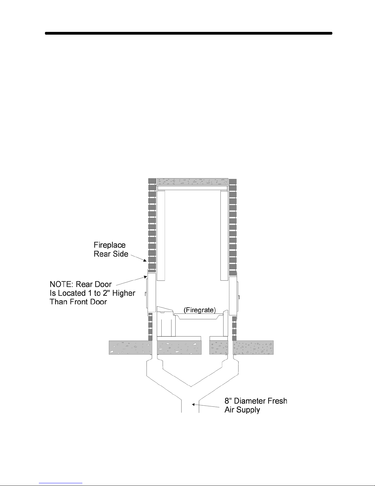
INSTALLING "See-Through" DOORS
The installation of a second set of fire doors
for a “See-Through” Fireplace will follow
the same steps as previously detailed.
However, the finished height of the rear
doors will be about 1.5" (380mm) higher
than the front doors. (Refer to Fig. 16).
This dimension can be adjusted down a
little, but care must be taken so that the door
frame is sealed against the ceramic gasket
on all four sides of the firebox opening and
sill to Part #7ST results. (It is important that
air enters the firebox only from the slots in
the top of the door frame.)
In addition, the installer must ensure that
half of the 8” dia. combustion air supply is
fed to the second door, and that an identical
2”x15” air slot is created behind the facade,
under the door frame, on the rear side of the
fireplace. (Without this provision, the rear
doors will not have an air wash and will
become dirty.)
a reasonably smooth transition from the door
Fig 16
Temp-Cast 2000 Installation Manual
Page 44
Section 4 – Installation of Door Frames & Facades
44
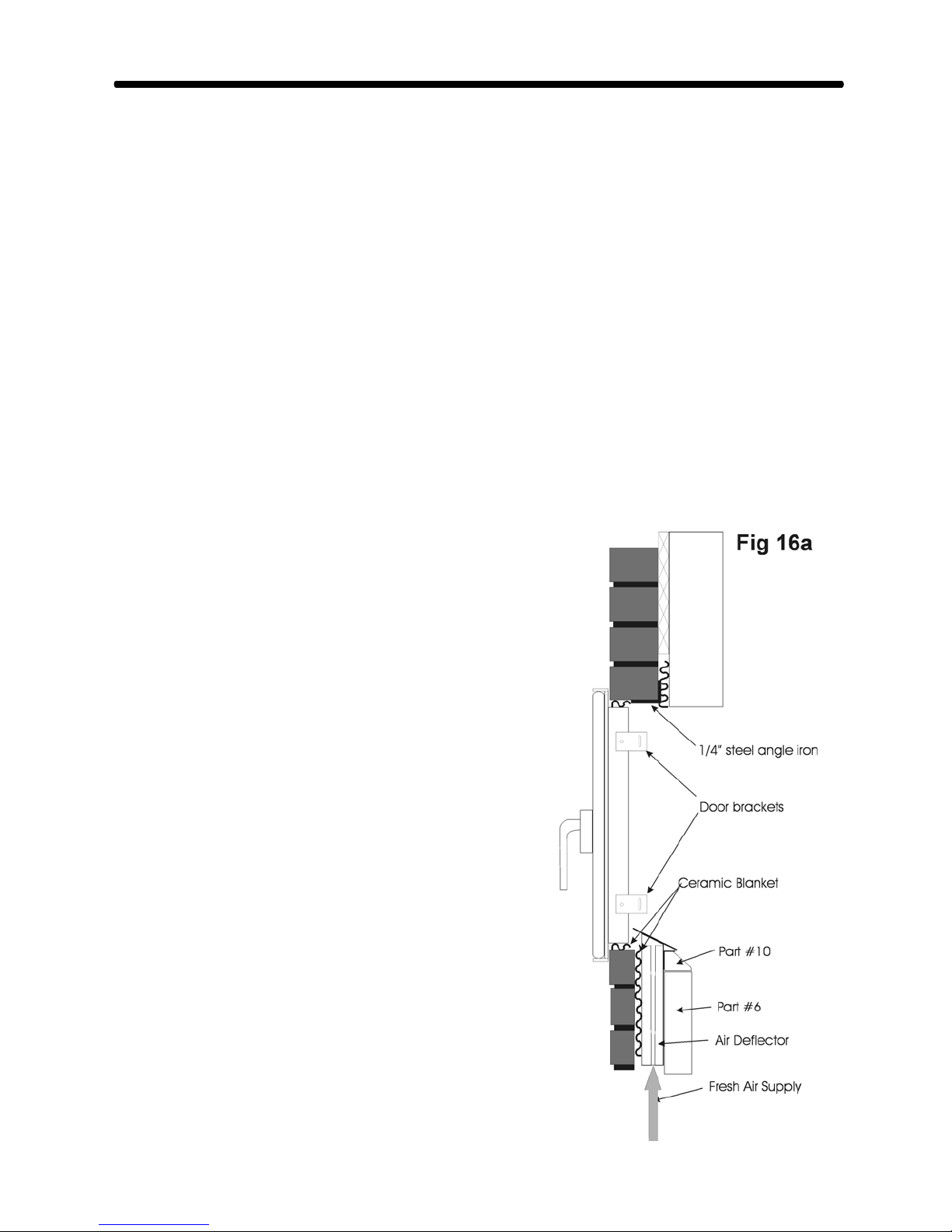
INSTALLING SQUARE FIRE DOORS
The Temp-Cast square door system
installation differs from the arched door
installation. In the square door system, air
delivery and air wash is created with an air
deflector. In addition, a ¼” angle iron lintel
must be used over the square door to support
facing materials.
Although experienced heater masons may
use a different technique to attach the
doorframe, the following method ensures
three critical points:
The doorframe MUST NOT be attached
permanently to the refractory core.
(Thermal expansion of the refractory
core and the door may cause lifting or
STEP TWO
Using the door as a template, trace it’s
position onto the corrugated spacer, ensuring
that the door completely covers the firebox
opening. In addition, ensure that the door
and air deflector are positioned so that air is
directed onto the glass near the bottom of
the door.
STEP THREE
Measure 2” in from the previously traced
door line, towards the firebox opening, on
all four sides. Cut away this strip of
corrugated spacer.
Using a small amount of refractory mortar,
glue a 2” strip of ceramic fibre to this area.
cracking of the facing material.)
The air deflector must be correctly
positioned to channel the air from the air
slot into the bottom of the door glass
and into the firebox, as in Fig. 16a.
The doorframe must completely cover
the firebox opening.
STEP ONE
Installation of the Temp-Cast square door
system can begin after the refractory core
has been assembled and the corrugated
spacer attached.
Cut the corrugated spacer from the firebox
opening and remove the spacer from the
area under the door, where the air deflector
will be installed. (See Fig. 16a)
STEP TWO
Place the air deflector in position as shown
in Fig 16a. It should rest on top of part #10
& be centered in the opening over the air
slot. It should be installed tightly to the
outside of the core.
Temp-Cast 2000 Installation Manual
Page 45

Section 4 – Installation of Door Frames & Facades
45
STEP FOUR
The facing material can now be applied, up
to the bottom of the door. The façade
should be planned so that the firebox
opening will be approx. 1” bigger than the
inner flange of the door frame – creating an
opening of approx 18 ½” high and 20 ¾”
wide. (This ½ “ space will eventually be
filled with ceramic fibre to create an
expansion & smoke gasket.)
(Note: follow the guidelines for installing
the facing material, as described in the
section "INSTALLING THE FACADE")
In addition, a ¼” steel angle iron must be
used as a lintel to support the masonry over
the door. Note the placement of ceramic
fibre around the doorframe and the steel
lintel, in order to create expansion gaskets.
The ends of the angle iron must also be
wrapped with ceramic fibre, so that
horizontal expansion of the angle iron will
not affect the facing material adjacent to
the ends of the lintel.
STEP FIVE
Lay a strip of ceramic fibre on top of the last
course below the door opening & position
the door in the opening, resting on the
ceramic fibre.
The door is attached to the facing
material (never to the core
), using the
brackets provided. When using brick or
block facing, the attachment bolts can be
laid in a mortar joint, or the back of the
brick or block can be cut & re-filled if a
mortar joint is not convenient. (The
bracket has a slot for the bolts, so in most
cases it can be moved to line up with a
joint.) When using other materials, which
cannot be easily cut or chipped (such as
river rock), then joints will have to be
more carefully planned to line up with the
slots in the brackets. (Alternately,
another hole could be drilled in the frame
to move the bracket in line with the rock
joints.)
When the facing material is complete,
loosely pack some ceramic fibre between the
doorframe and the facing on the remaining 2
sides and the top, to act as an expansion
gasket and smoke break. (It should be
slightly compressed, but do not pack the
ceramic fibre tightly into this opening,
which will prevent the gasket from
compressing as the door heats up. A small
amount of refractory mortar can be used to
hold the gasket in place, applied to the
firebox side of the gasket.)
SEE-THRU DOORS
The installation of a second square door will
be required with the See-thru option. It
should be installed in the same manner as
the first door, except that the rear door will
be about 1.5” higher than the front door. In
addition, the rear air deflector will rest on
Part #7ST, but will positioned in a similar
manner as the front deflector, in relationship
to the doorframe and the air slot from below.
(i.e. It must also direct air onto the bottom of
the door glass and into the firebox.) (See
Fig 16).
Temp-Cast 2000 Installation Manual
Page 46
Section 4 – Installation of Door Frames & Facades
46
INSTALLING BAKE OVEN DOORS
We recommend that the Bake Oven door
be installed directly on the core, (with a
gasket and/or optional Trim Plate), in
contrast to the fire doors. Without the
benefit of an "air wash", the door glass
will tend to stay cleaner if it is as close as
possible to the fire. (In this case, the door
frame is installed before the facade
reaches this level.)
Some installers may want to install it on
the facade, without a Trim Plate, which
may be acceptable only if the appearance
of the glass is not a consideration.
To make the installation simpler, tap the
hinge pin out of the hinge and remove the
door from the frame.
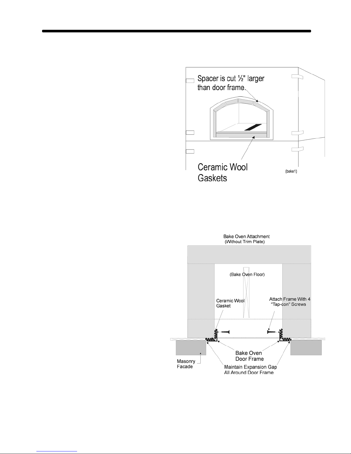
WITHOUT THE TRIM PLATE
Use the frame as a template & cut out the
cardboard spacer from around the bake
oven, allowing an extra 1/2" (12.5mm).
Glue a 1" (25mm) wide strip of ceramic
wool to the door sill. Also glue 1” strips
of ceramic wool around the opening, so
that a gasket is formed between the door
frame and the core. (Use ceramic wool pcs
K17 & K18) (See Fig. 17)
Position the door frame, level and plumb
it, and secure it with four "tap-con"
screws. Slight pressure should be used to
gently compress the ceramic gasket. Fill
any remaining gaps between top and sides
of the frame and the bake oven opening
with ceramic wool. (See Fig. 18)
Fig. 17
Fig. 18
Temp-Cast 2000 Installation Manual
Page 47
Section 4 – Installation of Door Frames & Facades
47
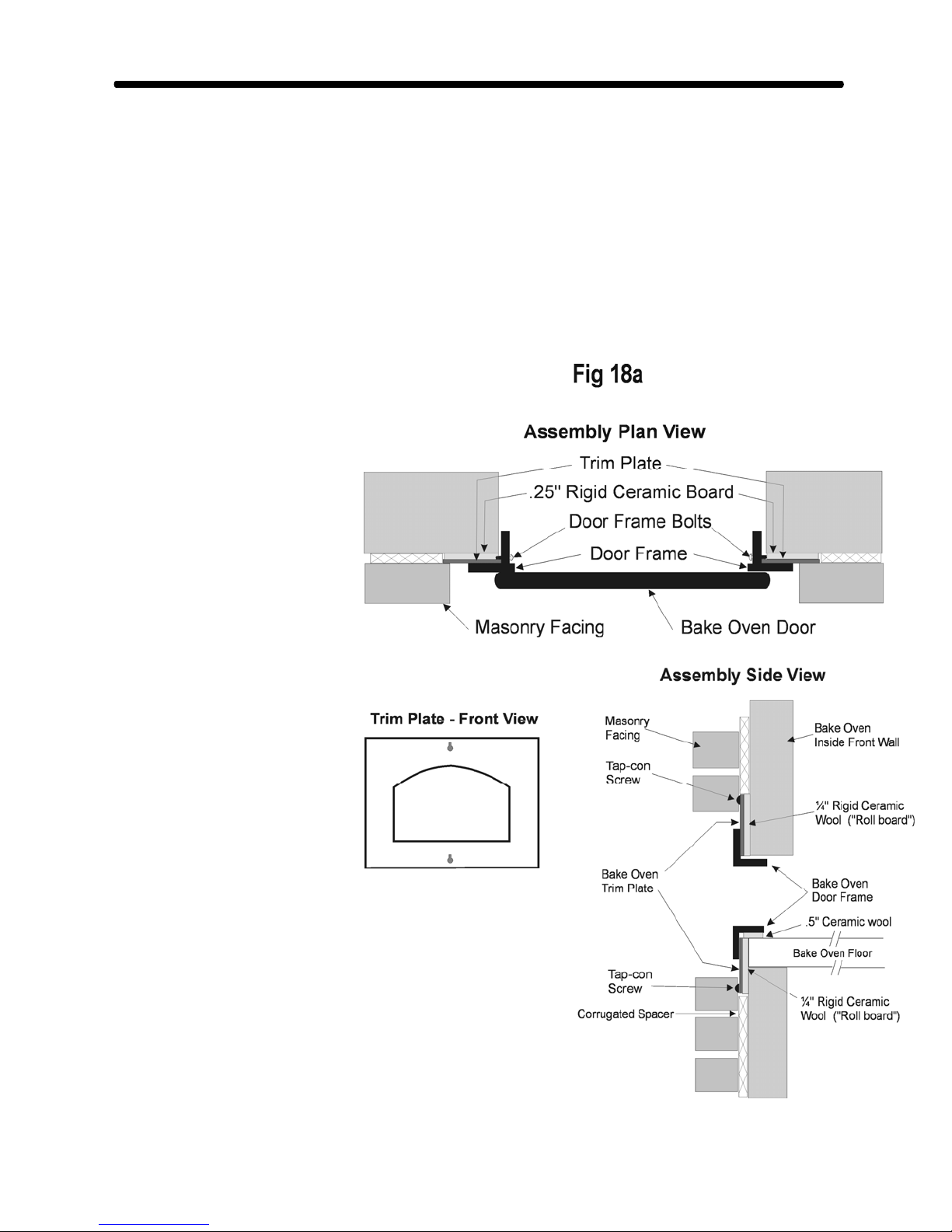
THE TRIM PLATE OPTION:
The Bake Oven Trim Plate option simplifies
the installation and creates a neater finished
appearance. With the trim plate in position,
the masonry facade can be set away from the
door frame without exposing the heater core.
To install the trim plate, cut out the opening
of the bake oven in the corrugated spacer.
Hold the trim plate in position and mark the
machine screws supplied, which go behind
the trim plate. Check that it is level and
plumb. (Leave the door off or cover it to
keep it clean during masonry work.)
Note: when the masonry facing is
installed, a space of 1 to 1½” must be left
between the door and the masonry to allow
the door to fully open & for full movement
of the door handle. (See Fig 18a.)
rectangle of the trim plate on the corrugated
spacer. Cut the spacer out of
this area.
Using the trim plate as a
template, cut a piece of 1/4”
rigid “coreboard” ceramic fibre
(supplied). Centre this fibre in
the opening and glue it to the
core with refractory cement.
Attach the trim plate to the core
with the tap-con screws
supplied.
Position the bake oven door
and attach it with the 4
Temp-Cast 2000 Installation Manual
Page 48
Section 4 – Installation of Door Frames & Facades
48
INSTALLING THE FACADE
Most facades will be installed by
professional masons, who will have their
own methods of planning and working.
(Refer also to “FACADE/FLANGE
OPTIONS” earlier in this section.)
Several details concerning the installation of
the masonry facade are unique to Temp-Cast
fireplaces and must be considered.
These points must be followed during the
installation of the facade:
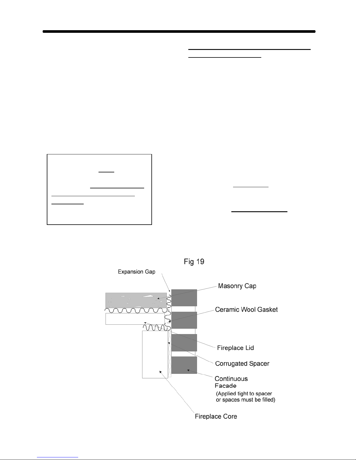
All spaces between corrugated spacer
and masonry facing must be filled. DO
NOT LEAVE AN AIR SPACE
BETWEEN FACING AND HEATER
CORE!!!(See Fig. #19)
The masonry courses directly below the
fire doors must be sliced in half or
stepped out. This will provide a
permanent air slot, which will feed
combustion air from below into the
bottom of the door frame and into the
WARNING!
It is important that no air be able to
get into the space between heater
core & facing - on all 4 sides and the
top & around firebox & bakeoven
door frames. FAILURE TO SEAL
THESE SPACES MAY RESULT IN
A FIRE HAZARD.
fire. (See Fig # 1a & 1b.)
An expansion break must be created
between the masonry cap & the facing,
to allow for unrestricted vertical
expansion of the core. (See Figs. 19 &
20)
The facade must be continuous on all
four sides and top of the heater. The
heater core must not be left exposed at
any point.
Temp-Cast 2000 Installation Manual
Page 49
Section 4 – Installation of Door Frames & Facades
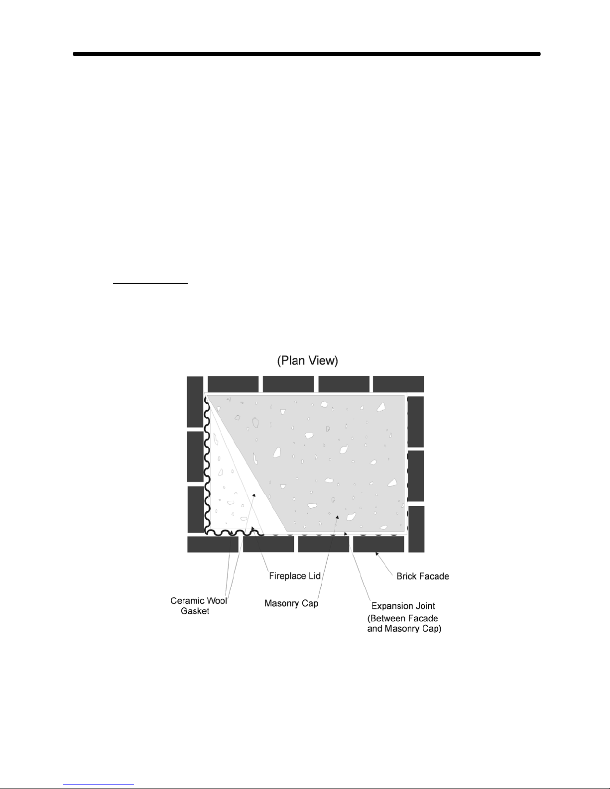
THE MASONRY CAP
The facade must be continued at least 4"
(100mm) above the top of the fireplace
modules.
Fill the resulting space between facade and
sides of the fireplace lid with ceramic wool.
Place a layer of 1/2" (12mm) ceramic wool
(pc K23) on top of the fireplace, ensuring
that it runs up the sides and ends of the
facade. (See Figs.19 & 20)
A continuous masonry cap of at least 2"
(50mm) must be added to the top of the
fireplace. It can be poured concrete, stone,
brick or other solid masonry material.
(Remember to include an expansion joint.-
refer to Figs. 19 & 20.)
The facade can
now be continued
to the ceiling, if
desired. In this case, open spaces should be
created in the top course of the masonry
facade or decorative metal grills should be
installed, to vent the trapped heat and
humidity.
The installation of your Temp-Cast fireplace
is now complete. The fire can be lit
immediately to begin the curing process or
left with doors and dampers open in warm
weather to allow trapped moisture to escape.
IMPORTANT!! Before firing the heater,
refer to the Owner's Manual for curing
and firing procedures.
49
Fig. 20
Temp-Cast 2000 Installation Manual
Page 50

Section 5 –Avoiding Installation Errors
50
SECTION 5: AVOIDING INSTALLATION ERRORS
The Temp-Cast modular system was designed to be as "fool-proof" as possible and is easily and
properly installed when the instructions are followed. Unfortunately, every year, one or two installers do
not read or follow the instructions, resulting in a costly repair. This section reinforces the most
important installation points which cannot be ignored or altered
Review this list before starting the installation and as the work progresses, especially if you are hiring
someone to do the installation. If both you and your installer follow this check-list, the likelihood of errors
is greatly reduced.)
1. ALL AIR-SPACES
MUST BE BACK-FILLED WITH MORTAR. (Air spaces between facing and corrugated spacer will
restrict the heating output of your unit to as little as 20% of its design capability. This is a very
costly error to fix – the entire facing must be removed and correctly re-installed.)
2. DO NOT USE CONCRETE BLOCKS AS A FACADE. (Concrete blocks are difficult to properly
back-fill behind without air spaces, especially if they are cut for fitting. We suggest only a brick,
natural stone or natural rock facing with a minimum 4” thickness but not more than 6”.)
3. A MASONRY FACADE MUST
EVEN IF SOME AREAS WILL NOT BE VISIBLE. (Failure to have a continuous masonry
façade of at least 4” thickness on all 4 sides and top of the heater will create a fire hazard,
which could cause property damage, personal injury or death!!)
4. ENSURE THE CORRUGATED SPACER IS ATTACHED TO ALL 4 SIDES
BEFORE STARTING THE FACING. )
5. THE SPACE BETWEEN THE BACK OF THE DOOR FRAME AND HEATER CORE MUST BE
SEALED WITH CERAMIC WOOL. (This will prevent any combustion gases from leaking out
around the door frame.
6. DURING TRIAL FITTING, ENSURE THAT THE AIR SLOT IN THE BOTTOM OF THE DOOR
FRAME IS ALIGNED WITH THE AIR SLOT IN THE CONCRETE PAD. (This is the reason the
frame cannot be mounted on the outside of the masonry work when the facade is thicker than 4" the air slot will not line up properly. If you purchased the Temp-Cast “square” door system, a
special air-deflector will be included.)
7. THE AIR SLOT BETWEEN THE BOTTOM OF THE DOOR FRAME AND THE CONCRETE PAD
MUST NOT BE OBSTRUCTED. (The facing under the door frame must be “cut” to create a 2” x 15”
air slot & this space must be kept free of rough masonry, mortar, ceramic wool or other debris.)
8. PROVIDE ADDITIONAL COMBUSTION AIR AND A NON-COMBUSTIBLE HEARTH FOR BOTH
DOORS OF A "SEE-THROUGH" FIREPLACE. (8” dia. of air needed, divided between the 2 doors.
This creates an air-wash for each glass door. See Fig. 16.)
9. PROVIDE AN EXPANSION JOINT ON TOP, BETWEEN MASONRY CAP AND MASONRY
FACADE. (To prevent cracks caused by vertical expansion of the core.)
BETWEEN THE MASONRY FACING AND THE CORRUGATED SPACER
BE INSTALLED ON ALL 4 SIDES AND TOP OF THE HEATER,
for a safe and effective heater.
OF THE CORE
Temp-Cast 2000 Installation Manual
Page 51
Section 6 –Ceramic Wood Cutting Plan
51
Temp-Cast 2000 Installation Manual
Page 52
Section 6 –Ceramic Wood Cutting Plan
52
Temp-Cast 2000 Installation Manual
Page 53
Section 7 –Warranty
53
TEMP-CAST ENVIROHEAT LTD WARRANTY
Temp-Cast Enviroheat Ltd. warrants, subject to the conditions and exceptions noted below, that
should this product become defective due to materials or workmanship within the specified
warranty period, Temp-Cast Enviroheat Ltd. will repair or replace the defective part, at its option.
WARRANTY PERIOD
Refractory Parts: FIVE Years from date of purchase
Metal Parts: One Year from date of purchase
EXCEPTIONS
The following are not covered by this warranty:
1. Glass components
2. Stress cracks in the refractory caused by normal thermal expansion.
3. Defects or cracks of any kind in the masonry facade.
4. Any other materials or labour, including removal and replacement of masonry facades.
5. Damage caused by incorrect installation, or by failing to follow Temp-Cast installation instructions.
6. Damage caused by incorrect operation or abuse, or by failing to follow Temp-Cast curing and
operating instructions.
CONDITIONS
1. Registration Card must be completed and mailed within 30 days of installation to Temp-Cast
Enviroheat Ltd, 3409 Yonge St, Bedford Park Postal Outlet, Box 94059, Toronto, Ontario,
Canada, M4N 3R1.
2. At least 4 Installation Photos (or video) must be included with the Registration Card, showing the
completed core, the core with partial facade erected, the completed installation and one showing a
normal fire, following the curing process - this photo can be sent separately at a later date.
3. All defective parts must be properly crated and shipped pre-paid to the Factory.
4. Proof of Purchase must be included, showing the date of retail purchase.
5. Temp-Cast must be contacted for approval prior to any part being returned for warranty claim.
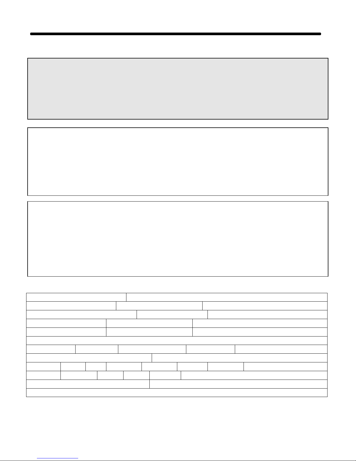
REGISTRATION CARD
NAME: STREET ADDRESS:
CITY: STATE/PROV: ZIP/POSTAL:
EMAIL: HOME TEL: BUS TEL:
PURCHASE DATE: INSTALL DATE: DEALER:
INSTALLER: INSTALLER CITY: INSTALLER PHONE:
OPTIONS INSTALLED:
PRIMARY PURPOSE?
FAÇADE MATERIAL: FAÇADE THICKNESS:
HOUSE TYPE:
HOUSE STYLE:
TOTAL HOUSE SIZE: AREA HEATED BY TEMPCAST:
COMMENTS: (use reverse also)
Main Heat Source
Frame
□ Log □ Timer Frame □ Post & Beam □ Straw Bale □ Earth/Adobe □ Concrete □
Bungalow
□ 2 Storey □ 3 Storey □ Split Level □ Other □
□ Zone/Supplementary Heat Only □ Decorative Fireplace □ Other□
Temp-Cast 2000 Installation Manual
 Loading...