

TEMIC U4076B-FL, U4076B Datasheet
Three-Tone Ringer for Telephone Sets
Description
The three-tone ringing integrated circuit U4076B, in
conjunction with a piezo transducer or loudspeaker
replaces the normal electromechanical telephone bell. It
is operated with the ringing current from the exchange.
Features
D
Three-tone ringing sequence with 800 Hz, 1067 Hz
and 1333 Hz
D
Sequence frequency adjustable between 2.5 Hz and
25 Hz
D
Adjustable volume
D
Push-pull output stage
D
Piezo transducer or loudspeaker connection
D
Common input for frequency and call recognition
There is also a possibility of operating the IC with the dc
supply voltage, being developed for large operating
range. The integrated circuit is overload protected.
D
Clock oscillator with ceramic resonator or LC series
cct possible
D
Input protective diode
D
On-chip rectifier bridge
D
Protection circuit against ringing in a parallel circuit
Benefit
U4076B
D
Reduced pulse duration for electromagnetic
transducers
22 F
m
4 (5) 6 (7) 10 (11) 8 (9)
7
5
Frequency
1
Three
state
a
~
~
b
m
0.8 F
R
2.2 k
L
W
(8)
(6)
14
(16)
(1)
Supply
Frequency
monitoring
W
600 k
Level
monitoring
Reset
b
D
Suitable for German Post Office Specification,
FTZ 121671 Pfl. 3, edition dated 24.03.82
W
43 k 4.7 nF
Tone sequence
oscillator
96 ms
127 ms
Divider
128:1
Divider
32:1
Divider
(10)9 (15) 13
Divider
2:1
Divider
14:1
Tone signal
generator
32:1
Reset
a
Ground: output signal
Open: output signal
Clock signal
generator
93 7792 e
12
(13)
11
(12)
2 (2)
3 (3)
100 k
log
455 kHz
W
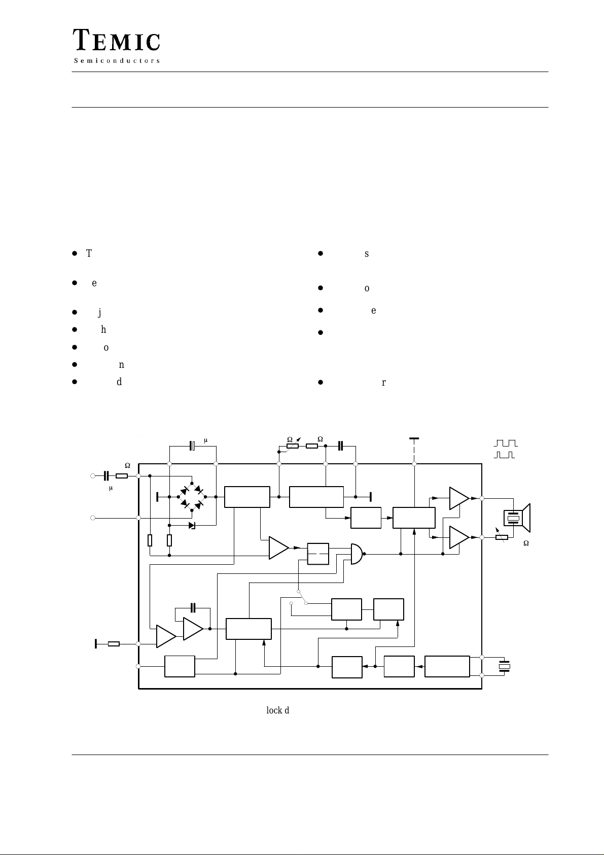
Case: DIP14 or SO16-L (Pin connections for SO 16-L case in bracket)
TELEFUNKEN Semiconductors
Rev . A1, 15-May-96
Figure 1. Block diagram and application circuit
1 (6)
Preliminary Information
U4076B
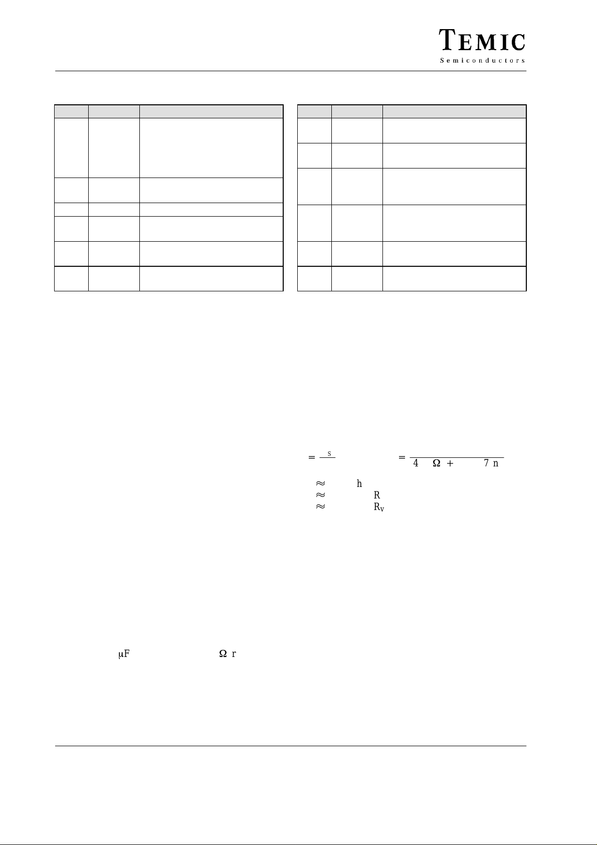
Pin Description
Pin Symbol Function
1 (1) Frequency monitoring
Open: 23 to 54 Hz
Ground: 12 to 54 Hz
With Pin 6 (7) connected:
Switched off
2, 3
(2, 3)
4 (5) Ground
5, 7
(6, 8)
6 (7) Charging capacitor, C
(8, 9,
10)
Clock signal generator
Power supply
bridge rectifier
Frequency oscillator
for
L,
Pin Connections and Functional
Description Including External
Circuitry
Pin 1: Frequency monitoring
Frequency is monitored via Pin 1. The following possibilities are available (three-state logic):
a) Pin 1 is open: ringing frequency is between 23 and
54 Hz.
b) Pin 1 is grounded: ringing frequency is between 12
and 54 Hz.
c) Pin 1 is connected to Pin 6 (7): ringing frequency has
no influence (dc operation)
Pins 2 and 3 (2, 3): Clock signal generator
A ceramic resonator for a frequency of 455 kHz must be
connected between Pin 2 (2) and Pin 3 (3). The clock
frequency of the generator is used for three-tone ringing
sequence and control signals for frequency identification.
Pin 4 (5): Ground
Reference point for all voltages.
Pins 5, 6 and 7 (6, 7, 8): Power supply
Pins 5 (6) and 7 (8) connect the circuit with a ringing ac
supplied by the exchange via lines a and b. A decoupling
capacitor of 1 mF in series with 2.2 kW resistance is
needed for overvoltage protection and the insertion loss
requirement of the German Post Office specifications.
The supplied ac current is rectified by the on-chip bridge
circuit. The rectified current charges the capacitor on
Pin 6 (7), which supplies the dc voltage for the integrated
Pin Symbol Function
8, 9,
10
(9, 10,
11)
11, 12
(12,
13)
13
(15)
14
(16)
(4,
14)
circuit. Instead of a ringing ac current supplied by the exchange, the IC can be driven by a dc voltage applied
directly to terminals 6 (7) (+) and 4 (5) (–). An integrated
Z diode limits the maximum supply voltage range up to
27 V.
Tone sequence
Frequency oscillator
Output signals
Output signal shape
Open = short pulse width
Ground = 1:1
Load resistance, R
Not connected
L
Pins 8, 9 and 10 (9, 10, 11):
Sequence frequency adjustment
The sequence of the three-tone ringing frequency (800,
1067 and 1333 Hz) is determined by the external network
calculated as follow:
f
OSC
+
f
2
if: k 0.95 then R
if: k 1 then R
if: k 1.2 then R
The sequence frequency adjustment is determined by the
frequency prescaler ratio in the IC.
192
whereas f
OSC
v
v
v
+
(43 kW)
= 0 to 20 kΩ
= 30 to 150 kΩ
> 200 kΩ
IC
R
)47nF
V
Pins 11 and 12 (12, 13): Output signal
The three-tone ringing sequence of 800 Hz, 1067 Hz and
1333 Hz is realized if the clock oscillator is synchronised
with a ceramic resonator of 455 kHz between Pins 2 (2)
and Pin 3 (3). This gives excellent tone frequency and
eliminates complicated frequency setting procedures.
The output signal without load is (2 V
output stage transducers in BTL configuration can process an average current of up to 20 mA, whereas a short
time current of 40 mA is possible in both direction when
t = 0.1 ms. An external current limitation is necessary
when the IC is operating with voltage between Pin 6(7)
and Pin 4 (5). The tone sequence always starts at the
lower frequency.
6(7)
– 2.5) V
pp.
The
2 (6)
TELEFUNKEN Semiconductors
Rev . A1, 15-May-96
Preliminary Information
 Loading...