


查询TS80C31X2供应商
Qualpack TSS463 / TSS461C
TSS463 VAN
Van Controller Serial Interface
TSS461C VAN
Van Controller
TSS463/TSS461C
VAN Controllers
1999 January
TEMIC SEMICONDUCTORS IS AN ATMEL COMPANY
Rev. 2 – January 1999 1

Qualpack TS80C31X2/C32X2
1. Contents
1. Contents........................................................................................................................................................ 2
2. General Information ..................................................................................................................................... 3
3. Technology Information .............................................................................................................................. 4
3.1 W
AFER PROCESS TECHNOLOGY ..................................................................................................................... 4
3.2 P
RODUCT DESIGN .......................................................................................................................................... 5
3.3 P
ACKAGE TECHNOLOGY ................................................................................................................................. 6
3.3.1 SOIC.300 16 leads ............................................................................................................................... 6
3.3.2 Other available packages .................................................................................................................... 7
3.4 T
EST ............................................................................................................................................................. 7
EVICE CROSS SECTION ................................................................................................................................8
3.5 D
3.6 W
AFER PROCESS CONTROL ........................................................................................................................... 9
4. Qualification ............................................................................................................................................... 10
HANGE PROCEDURE................................................................................................................................... 11
4.1 C
4.2 Q
UALIFICATION FLOW ................................................................................................................................... 12
AFER PROCESS QUALIFICATION ................................................................................................................. 13
4.3 W
4.4 P
ACKAGE QUALIFICATION ............................................................................................................................. 14
4.5 D
EVICE QUALIFICATION ................................................................................................................................16
4.5.1 ESD and Latch-up results .................................................................................................................. 17
4.5.2 Failure Mechanisms and Corrective Actions ..................................................................................... 17
4.5.3 Qualification status............................................................................................................................. 17
4.6 O
UTGOING QUALITY AND RELIABILITY ............................................................................................................ 18
4.6.1 AOQ (Average Outgoing Quality) ...................................................................................................... 18
4.6.2 EFR (Early Failure Rate).................................................................................................................... 19
4.6.3 LFR (Latent Failure Rate) .................................................................................................................. 19
5. User Information ........................................................................................................................................ 20
5.1 S
OLDERING RECOMMENDATIONS .................................................................................................................. 20
5.2 DRY PACK O
5.3 ESD
CAUTION .............................................................................................................................................. 20
RDERING RULES ..................................................................................................................... 20
6. Environmental Information ....................................................................................................................... 21
7. Other Data ................................................................................................................................................... 22
7.1 ISO9001 A
ATABOOK REFERENCE................................................................................................................................23
7.2 D
7.3 A
DDRESS REFERENCE .................................................................................................................................. 23
PPROVAL CERTIFICATE................................................................................................................ 22
8. Revision History......................................................................................................................................... 24
2 Rev. 2 – January 1999
Qualpack TSS463 / TSS461C
2. General Information
Product Name: TSS463 / TSS461C
Function: Van Controllers
Specific features: Serial Interface (TSS463)
Wafer process: Z86E
Available plastic package types: SOIC16 (TSS463), SOIC24 (TSS461C)
Locations:
Process, product development TEMIC Semiconductors Nantes, France
Wafer plant TEMIC Semiconductors Nantes, France
QC responsability TEMIC Semiconductors Nantes, France
Assembly ANAM, Korea, Philippines
Probe test TEMIC Semiconductors Nantes, France
Final test GATEWAY Philippines
Quality Assurance TEMIC Semiconductors Nantes, France
Reliability testing TEMIC Semiconductors Nantes, France
Failure analysis TEMIC Semiconductors Nantes, France
Quality Assurance Management Nantes
Signed..........................................................
ANAM Korea
Rev. 2 – January 1999 3

Qualpack TS80C31X2/C32X2
3. Technology Information
3.1 Wafer Process Technology
Process type (Name): CMOS (SCMOS1/2 - Z86E)
Base material: Silicon Epi substrate type
Wafer Thickness (final) 475um
Wafer diameter 150mm
Number of masks 13
Gate oxide
Material Silicon dioxide
Thickness 195 A
Polysilicon
Number of layers 1
Thickness 3000 A
Metal
Number of layers 2
Layer 1 material TiN/W
Layer 1 thickness 600 + 5000 A
Layer 2 material Ti/AlCu
Layer 2 thickness 7000 A
Passivation
Material Si
Thickness 10000 A
on SiO2
3N4
4 Rev. 2 – January 1999

Qualpack TSS463 / TSS461C
3.2 Product Design
Die size (TSS463) 11.15mm2 (3610µm*3280µm)
Die size (TSS461C) 8.46mm2 (3480µm*2610µm)
Logic Effective channel length 0.8µm
Gate poly width 0.8µm
Gate poly spacing 1.2µm
Metal 1 width 1.3um
Metal 1 spacing 1.5um
Metal 2 width 1.6um
Metal 2 spacing 1.6um
Contact size 1.0µm
Via size 1.4µm
Rev. 2 – January 1999 5

Qualpack TS80C31X2/C32X2
3.3 Package Technology
3.3.1 SOIC.300 16 leads
Package weight 0,43 g
Chip separation method Sawing
Lead frame
Material Cu
Thickness 10 mils
Size 270*270 mils
Lead plating Electroplated Sn/Pb 85/15
Die attach
Material Silver epoxy
Type Ablestick 84-1 LMISR4
Wire bonding
Material Gold
Diameter 33um
Method Thermosonic
Molding
Material Nitto MP8000AN
Flammability rating UL94V-0
Marking
Method Printed ink
Coding example TEMIC
optional special customer marking
TSS463
YY MM
2
Dry packing No
Tube packed
Primary Tube
Material Antistatic PVC
Number per unit 47
Secondary Box
Material Cardboard
Number per unit 1692
Labelling (minimum) Device type, Quantity, Date Code, Prod. code
Bar coding Code 39 to EIA-556-A
6 Rev. 2 – January 1999

Tape packed
Primary Tape
Material Antistatic PVC
Number per unit 31
Secondary Box
Material Cardboard
Number per unit 1116
Labelling (minimum) Device type, Quantity, Date Code, Prod. code
Bar coding Code 39 to EIA-556-A
3.3.2 Other available packages
No other package available
Dry packing
SOIC 16 No
SOIC 24 No
Qualpack TSS463 / TSS461C
3.4 Test
Probe equipement Sentry 15
Probe temperature 125°C
Test equipement Sentry 15
Test temperature 25°C, 125°C(sampling)
Rev. 2 – January 1999 7
Qualpack TS80C31X2/C32X2
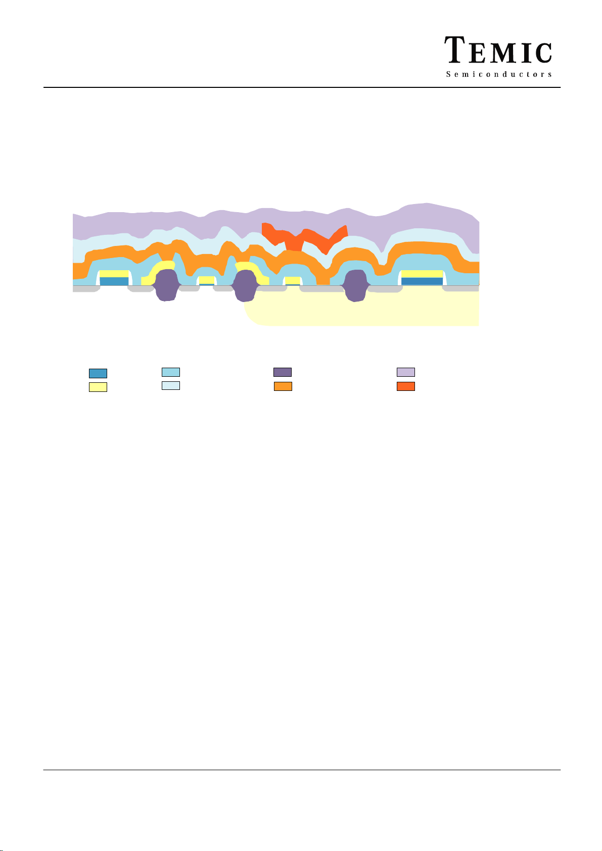
3.5 Device Cross Section
NNNNNN
NMOS
P
PMOS
PPP
N -
Epi Substrate
Thin Oxide
Polysilicon
Planararization
Transversal Isolation Oxide
Passivation
Metal 2Metal 1
8 Rev. 2 – January 1999

Qualpack TSS463 / TSS461C
3.6 Wafer Process Control
All the inspections and controls are defined as a process step in the production management software,
and are led by using a centralized SPC software. PC system could be summarized as follows:
Engineering Database
Physical
-
NANTES
hermetic packages
-
Subcontractors
plastic packages
:
:
-
NANTES
hermetic packages
-
S ub con trac tors
plastic package s
:
:
Critical process parameters are identified by using F.M.E.A. and other advanced tools.
Those parameters are followed in real time with the SPC methodology and their capability is measured
and monthly reported in the Operation Review.
For end 1997, the Cpk target is the following :
all parameters with Cpk above 1.67
% of all Parameters per Cpk categories
100%
80%
60%
40%
>2
<2
<1.67
20%
0%
1995 1996 Q1-
Q2
97
Rev. 2 – January 1999 9
Q3-
Q4
97
Obj.
98

Qualpack TS80C31X2/C32X2
g
yp
4. Qualification
Product
Wafer Process
Packa
e
Device T
e
(Design)
Qualification
All product qualifications are split into three distinct steps as shown above. This same procedure is also
used to qualify a change. Before a product is released for use, it must have been manufactured using a
qualified wafer and package process. Before a device is released for production processing, it must also
have successfully completed its required specific qualification.
The standard tests which are used for this procedure are shown in the section
"Qualification Flow"
Qualification
Qualification
10 Rev. 2 – January 1999

Qualpack TSS463 / TSS461C
4.1 Change Procedure
All changes are controlled by ECN (Engineering Change Notice). All major changes are notified to those
customers using products which are affected by the change.
A major change is defined as a change which affects the electrical and/or mechanical specification as
defined in the datasheet or which affects the following parameters as defined hereafter:
1 General Major Changes
1-1 Manufacturing line
1-2 Sequence of fabrication process cycle
1-3 Material
1-4 Electrical parameter
1-5 Dimension
1-6 Pad location
1-7 Die size
2 Changes specific to wafer fabrication area
2-1 Doping process
2-2 Gate oxide formation method
2-3 Equipement change
2-4 Layer thickness
2-5 Module dimensions
3 Changes specific to to assembly process area
3-1 Sawing process
3-2 Die attach process
3-3 Wire interconnect method
3-4 Molding process
3-5 Tinning process
4 Changes specific to test area
4-1 Specification limit
4-2 Test coverage reduction
4-3 Product identification
4-4 Final conditioning
Rev. 2 – January 1999 11

Qualpack TS80C31X2/C32X2
4.2 Qualification Flow
General Requirements for Plastic packaged CMOS IC
Standard Test Description Qualification type
(acceptance)
MIL-STD 883D
Method 1005
MIL-STD 883D
Method 1005
MIL-STD 883D
Method 3015.7
JEDEC 17
MHS
PAQA0046
MIL-STD 883D
Method 1010
MHS
PAQA0184
Electrical Life Test (Early Failure Rate)
12 hours 150°C (Tj) 5.75V
Electrical Life Test (Latent Failure Rate)
1000 hours 150°C 5.75V Dynamic or Static
Electrostatic Discharge HBM
+/-2000v 1.5kOhm/100pF/3 pulses
Latch up
50mW power injection 125°C
PROM Dataretention
High Temperature Storage 165°C
Temperature Cycling
1000 cycles -65°C/150°C air/air
Pressure Pot after Mounting Stress
168 hours 130°C/85%RH
Device
(1/2000 12h)
Device
(0/116 500h)
Device
(0/3 per level)
Device
(0/10)
Device
(0/45 500h)
Device and
Package
(0/45 500c)
Device and
Package
(0/45 168h)
EIA
JESD22-A101
EIA
JESD22-A110
85/85 Humidity Test
1000 hours 85°C/85%RH
HAST
336 hours 130°C/85%RH/5.5V
Die and Package
(0/45 500h)
Device and
Package
(0/45 168h)
EIA
JESD22-A112
MIL-STD 883D
Method 2003
MIL-STD 883D
Method 2015
12 Rev. 2 – January 1999
Resistance to Soldering Heat
Infra Red Stress 220°C/25s/3 times
Solderability
Marking Permanency
Package
(0/10 per class)
Package
(0/3)
Package
(0/3)

Qualpack TSS463 / TSS461C
4.3 Wafer Process Qualification
This section summarizes the global 1998 reliability results of the products manufactured with the same
technology as the VAN TSS463 and TSS461C (Z86 processes).
Wafer
Process
Z86 Microcontrollers
Z86
Z86
Z86 TSS461C EFR Dynamic Life Test
Global All products EFR Dynamic Life Test
Device Types Test Description Step Result Comment
EFR Dynamic Life Test
and dedicated
LFR Dynamic Life Test
Memory, Asic,
TSS463
EFR Dynamic Life Test
LFR Dynamic Life Test
EFR Dynamic Life Test
LFR Dynamic Life Test
LFR Dynamic Life Test
Failure mechanisms All 50%
12h
500h
1000h
12h
500h
1000h
12h
500h
1000h
12h
500h
1000h
12h
3/22888
1/1155
1/5209
1/685
Estimated 65 ppm
3.9 fit
Estimated 49 ppm
2.9 fit
Poly silicide defect
17%
17%
17%
4/28097
metal
resistor shift
bonding
165 ppm (20mm2)
LFR Life Test
Rev. 2 – January 1999 13
500h
1000h
2/1840
10 fit (20mm2)

Qualpack TS80C31X2/C32X2
4.4 Package Qualification
This section presents TSS463 and TSS461C package qualification results, including additional
measurements intending to fulfil Q100 Automotive Standard requirements.
Lot
Number
Z21538F TSS463
Z21997A TSS463
W28184C 29C461B
Z04948C TSS461C Thermal Cycles 500c
Device Type Test Description Step Result Comment
Thermal Cycles 1000c
in SO 16 (1)
85/85 Humidity 1000h
Resistance to Soldeting
Heat
HAST after Soldering
Stress (with 5.5v bias)
Thermal Cycles 500c
in SO 16 (2)
85/85 Humidity 500h
HAST after Soldering
Stress
165c HT Storage 500h
Physical Dimensions Visual 0/5
Bonding Destructive Tests
(4)
Resistance to Soldeting
Heat
Thermal Cycles 500c
in SO 24 (1)
85/85 Humidity 500h
HAST after Soldering
Stress
85/85 Humidity 500h
HAST after Soldering
Stress
HAST 5.5V 168h
2000c
2000h
Level 1
Level 3
168h 0/45
1000c
1000h
168h
SAM
1000h
WPBS0/30 (5)
Level 1
Level 2
Level 5
1000c
1000h
168h 0/45
1000c
1000h
168h 0/45
336h
0/45
0/45
0/45
0/45
1/10
0/10
0/45
0/45 (3)
0/45
0/45 (3)
0/45 (3)
0/10
0/45
0/45
0/30
0/10
0/10
0/10
0/45
0/45
0/45
0/45
0/45
0/45
0/45
0/45
0/45
0/45
1 die top delamination
AVG=77.3 STD=8.9 CPK=1.8
MAX=98.9 MIN=61.1
AVG=17.4 STD=1.5 CPK=2.3
MAX=21.1 MIN=14.3
14 Rev. 2 – January 1999

Qualpack TSS463 / TSS461C
Lot
Number
Z20569K HMT-65664A
Global All products Mounting Stress level 1 Elect. 0/255 0 ppm
Device Type Test Description Step Result Comment
in SO 28 (2)
Thermal Cycles 500c
1000c
85/85 Humidity 500h
1000h
2000h
Resistance to Soldeting
Heat
Marking Permanency - 0/3
HAST after Soldering
Stress (with 5.5v bias)
Climatic Tests - 0/720 0 %
Level 1 0/10
168h 0/45
0/45
0/45
0/45
0/45
0/45
Notes:
(1) SUMITOMO 6300 molding compound
(2) NITTO MP8000 molding compound
(3) Electrical test with Quality program at 25°c, 125°c and -40°c
(4) Performed on molded device opened using acid
(5) No Lifted Ball Bond, breakdown observed on wires (83%) and over the stich (17%)
Rev. 2 – January 1999 15

Qualpack TS80C31X2/C32X2
4.5 Device Qualification
This section presents TSS463 and TSS461C device qualification results, including additional
measurements intending to fulfil Q100 Automotive Standard requirements.
Lot
Device Type Test Description Step ResultComment
Number
Z21538F TSS463
in SO 16
Z21997 TSS463
in SO 16
W28184C 29C461B
in SO 24
Z04948C TSS461C
in SO 24
Global All products EFR Dynamic Life Test 12h 0/1655 0 ppm measured
EFR Dynamic Life Test 12h 0/261
LFR Dynamic Life Test 500h
1000h
EFR Dynamic Life Test 12h
48h
LFR Dynamic Life Test 500h
1000h
EFR Dynamic Life Test 12h 0/298
LFR Dynamic Life Test 500h
1000h
EFR Dynamic Life Test 12h 0/296
LFR Dynamic Life Test 500h
1000h
LFR Dynamic Life Test 500h
1000h
0/116
0/116
0/800
0/304
0/45
0/45
(6)
0/72
0/72
0/78
0/78
0/311
0/311
18 fit measured
Notes:
(6) Electrical test with Quality program at 25°c, 125°c and -40°c
16 Rev. 2 – January 1999

4.5.1 ESD and Latch-up results
Qualpack TSS463 / TSS461C
Lot
Device Type Test Description Step ResultComment
Number
Z21538B TSS463
SO 16
Z19814 TSS461C
DIL 24.3
TSS461C Latch up Vcc
ESD HBM model
ESD CDM model
Latch up Vcc
overstress
LU power injection
ESD HBM model
ESD CDM model
overstress
LU power injection
3000v
4000v
4500v
5000v
1500v
10v
50mW
3000v
4000v
1500v
10v
50mW
0/10
1/13
0/4
3/13
0/10
0/10
0/10
0/5
3/3
0/4
0/10
0/10
CLASS 2
Leackage pin 6
Leackages pin 2,6,15
CLASS C6 (EOS/ESD of
association)
CLASS 2
Leakages
CLASS C6
4.5.2 Failure Mechanisms and Corrective Actions
Failure Mechanism Root Cause Corrective Action Date Effect Check of
Efficiency
Poly silicide
defects
Die top
delamination
Process
conditions
Sumitomo630
0 molding
compound
Reduce silicide
temperature,
increase duration
Move to Nitto
MP8000
Nov 97 Robusteness
improved
Jan 98 No more
moitures
sensitivity
EFR monitoring
pass level 1 of
JESD 22 A112
4.5.3 Qualification status
The Wafer Process and the assembly are qualified and controlled by regular monitoring.
The TSS461C VAN is full qualified since 1996 July.
The TSS463 VAN is full qualified since 1997 October.
Additional measurements done in 1998 and generic results demonstrate compliance of the two products
to Q100 Automotive Standard.
Rev. 2 – January 1999 17

Qualpack TS80C31X2/C32X2
Outgoing Quality and Reliability
4.5.4 AOQ (Average Outgoing Quality)
The AOQ is measured following 100% test by sampling outgoing product. The results of this inspection
are recorded in ppm (parts per million) using the method defined in JEDEC 16. The figures below cover
the last years for both the subject and structurally similar products.
200
150
ppm
100
50
0
1991
1992
1993
1994
1995
1996
1997
1998 ( O bj)
Year
18 Rev. 2 – January 1999

Qualpack TSS463 / TSS461C
4.5.5 EFR (Early Failure Rate)
The EFR is measured on a sample of devices by operating them at an elevated temperature and
measuring the number which fails to meet specification after 12 hours at 150°C. The figure is expressed
in terms of ppm.
1000
800
600
ppm
400
200
0
1991 1992 1993 1994 1995 1996 1997 1998 ( Obj)
Year
4.5.6 LFR (Latent Failure Rate)
The LFR is measured by operating devices at elevated temperatures for 1000 hours and measuring the
failure rate. Using the Arrhenius law, the expected failure rate at a operating temperature of 55°C is
calculated using an activation Energy of 0.6 eV with a confidence level of 60%. This is expressed in units
per billion hours (FIT).
100
80
60
FIT
40
20
0
1991 1992 1993 1994 1995 1996 1997 1998 ( O bj)
Year
Rev. 2 – January 1999 19

Qualpack TS80C31X2/C32X2
5. User Information
5.1 Soldering Recommendations
For DRY PACKED products, TEMIC recommends to strictly follow the procedure described
hereunder:
- Dry packed products must not be stored more than 1 year at 40°c - 90%rh
(worst storage conditions assumed)
- A longer storage period is allowed taking into account the following conditions:
5 years max at 25°c (+/-5°c) - 50%rh
- From opening of the packs, the product must be assembled within 48 hours.
(worst in-process storage condition assumed: 30°c - 60%rh)
- If they cannot be soldered within this time period, then the pieces must be dryed at
125°c for 24 hours. Only one drying is allowed.
- Max relative humidity allowed in the bag is 20% (readable on the indicator inside
the bag). If this value is reached, then the parts must be dryed at 125°C for
24 hours before mounting.
- For high sensitive products, the delay between pack opening and assembly is
reduced to 6 hours (Level 6 of JEDEC 22-A112). In this case, a warning printed on
each pack advises the user of this restriction .
5.2 DRY PACK Ordering rules
TEMIC qualification procedure allows to classify products according to JEDEC 22-A112 and to
determine the convenient conditioning for safe customer use.
Nevertheless, even if the product is not classified as moisture sensitive, it is possible (for example if
storage conditions are not properly controlled) to order product with a Dry Pack.
In this case the product name suffix will be ":D" or ":xD".
5.3 ESD caution
The user must protect components against EOS and ESD damages by grounding personal and
workstations.
20 Rev. 2 – January 1999

Qualpack TSS463 / TSS461C
6. Environmental Information
The TEMIC Environmental Policy aims at:
- Reducing the use of harmful chemicals in its processes
- Reducing the content of harmful materials in its products
- Using re-cyclable materials wherever possible
- Reducing the energy content of its products
As part of that plan, Ozone Depleting Chemicals are being replaced either by TEMIC / MHS or its subcontractor's processes.
Rev. 2 – January 1999 21

Qualpack TS80C31X2/C32X2
7. Other Data
7.1 ISO9001 Approval Certificate
22 Rev. 2 – January 1999

Qualpack TSS463 / TSS461C
7.2 Databook Reference
Direct access on the web to datasheet at:
http://www.temic-semi.com
Select: Products
Automotive ICs
Multiplex ICs
7.3 Address Reference
All enquiries relating to this document should be addressed to the following:
TEMIC Semiconductors
BP70602
44306 Nantes Cedex 3
France
Telephone (33) 2 40 18 18 18
Telefax (33) 2 40 18 19 20
Or direct contact same address
Pascal LECUYER
Quality Engineer
Telephone (33) 2 40 18 17 73
Telefax (33) 2 40 18 19 00
Rev. 2 – January 1999 23

Qualpack TS80C31X2/C32X2
8. Revision History
Issue Modification Notice Application Date
0 TSS463 VAN Qualification Report 1997 October
1 Qualpack TSS463 Van 1998 February
2 Qualpack TSS463 and TSS461C VAN CONTROLLERS 1999 January
Remarks:
The information given in this document is believed to be accurate and reliable. However, no
responsibility is assumed by TEMIC for its use. No specific guarantee or warranty is implied or given by
this data unless agreed in writing elsewhere.
TEMIC reserve the right to update or modify this information without notification , at any time, in the
interest of providing the latest information.
Parts of this publication may be reproduced without special permission on the condition that our author
and source are quoted and that two copies of such extracts are placed at our disposal after publication.
Before use of such reproduced material the user should check that the information is current.
Written permission must be obtained from the publisher for complete reprints or translations.
24 Rev. 2 – January 1999
 Loading...