

TEMIC TOIM3232, TOIM3000 Datasheet
TOIM3000/3232
Infrared IrDA Integrated Interface Circuits
ULC-Technology: High-performance gate array package using dual metal layer CMOS technology, featuring
sub-micronic channel length (0.8 mm)
Description
The TOIM3xxx series ICs provide proper timing for the
front end infrared transceiver TFDS3000, as specified by
the IrDA standard. In the transmit mode, the TOIM3xxx
provides IrDA-compatible electrical pulses to the infrared transceiver TFDS3000 on logic LOW electrical
input. In the receive mode, the TOIM3xxx stretches received infrared pulses to the proper bit width at the
operating bit rate. The IrDA bit rate varies from 2.4 to
115.2 kbit/s.
D
For the UART interface, the TOIM3000 uses the
1.8432 MHz clock input as the fast clock and the baud
clock output from the UART to do the pulse stretching
and shortening. The baud clock is 16 times the baud
rate. The output pulses are fixed at 1.627 ms or 3/16 of
bit time.
D
For the RS232 interface, the TOIM3232 uses an external crystal clock 3.6864 MHz for its pulse stretching
and shortening. The TOIM3232 is programmable to
operate from 1200 bit/s to 115.2 kbit/s by the communication software through the RS232 port. Output
pulses are software-programmable as either 1.627 ms
or 3/16 of bit time.
The typical power consumption of both circuits is very
low with about 10 mW in operational state. It is in the order of magnitude of microwatts in standby mode.
Features
TOIM3000
D
Pulse shaping function (shortening and stretching)
used in infrared IrDA standard applications
D
Directly interfaces the infrared transceiver
TFDS3000
D
3 V and 5 V operation with low operating current
D
SO16L package
*)
TFDS3000 is an infrared IrDA transceiver made by TEMIC
*)
to a UART or a microcontroller
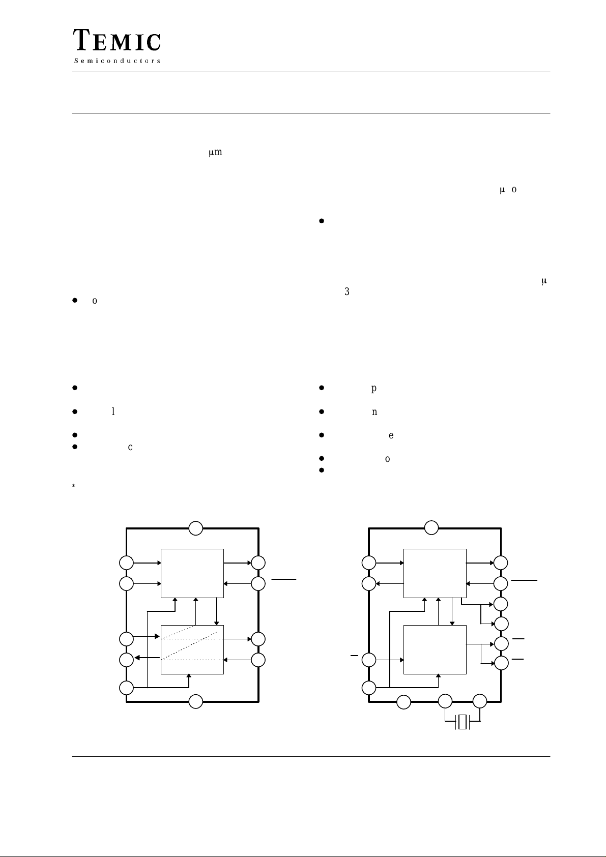
Block Diagrams
V
CC
XIN
B_CLK
TD_UART
RD_UART
Pulse
shaper
TD_IR
RD_IR
TD_232
RD_232
TOIM3232
D
Pulse shaping function (shortening and stretching)
used in infrared IrDA standard applications
D
Directly interfaces the infrared transceiver
TFDS3000
D
Programmable baud clock generator
(1200 Hz ∼ 115 kHz), 13 baud rates
D
3 V and 5 V operation
D
SO16L package
TD_232
RD_232
*)
to an RS232 port
V
CC
Pulse
shaper
Baud
clock
BR/D
generator
TD_IR
RD_IR
TD_LED
RD_LED
S1
S2
RESET
GND
TOIM3000 TOIM3232
TELEFUNKEN Semiconductors
Rev . A4, 26-Mar-96
RESET
Preliminary Information
GND
X1
X2
3.6864 MHz
1 (9)
TOIM3000/3232
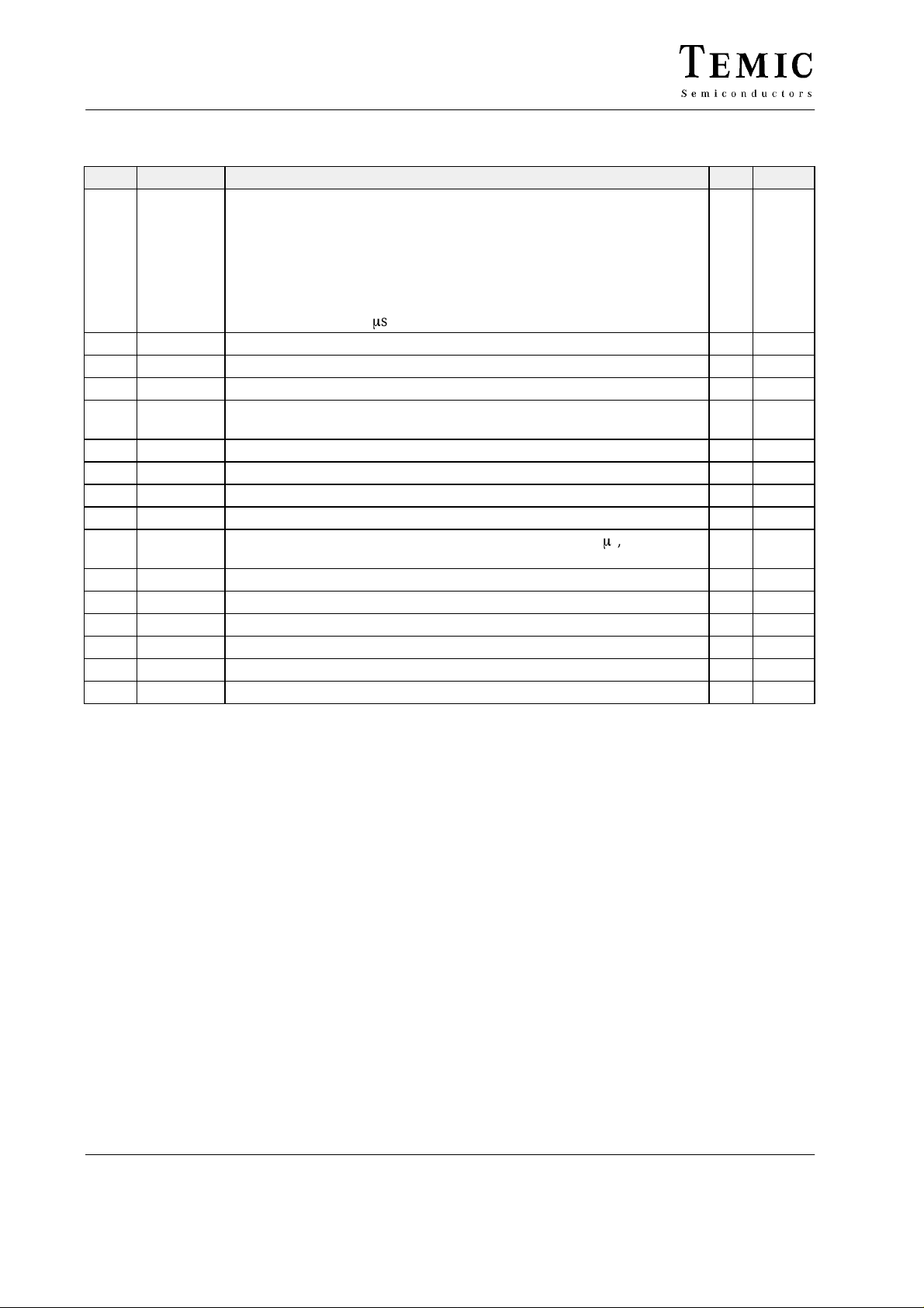
Pin Description TOIM3000
Pin Symbol Function I/Q Active
1 RESET Resets all internal registers. Initially must be HIGH to reset internal regis-
ters. When LOW, the TOIM3000 connects the UART with IrDA transceiver. Data received from the UART transmits out through the infrared
transmitter. Data received from the infrared receiver is routed to the
UART. When HIGH, the TOIM3000 connects the UART with the RS232
port. Data received from the UART transmits out through the RS232 port,
while data received from the RS232 port is routed to the UART. Minimum
hold time for reset is 1 ms.
2 RD_UART Received data to the UART O LOW
3 TD_UART Data fom the UART to be transmitted I LOW
4 B_CLK 16 times baud rate clock, input from the UART (Baudout) I
5 XIN Oscillator input, 1.8432 MHz clock (to be connected to Xout pin of the
UAR T)
6 NC No connection
7 NC No connection
8 GND Ground in common with the UART and RS232 port
9 S0 Must be connected to GND
10 S1 Must be connected to GND for output pulse length of 1.627 ms,
Connected to V
11 RD_232 Data input from the RS232 port, RXD pin I LOW
12 TD_232 Data output to the RS232 port, TXD pin O LOW
13 NC No connection
14 TD_IR Data output to infrared transmitter TFDS3000 O HIGH
15 RD_IR Data receive input from the infrared transmitter TFDS3000 I LOW
16 V
*)
CC
The use of a pulse length of 3/16 of bit duration is not recommended when both clocks, Xout and Baudout,
of the UART are available
Supply voltage
for pulse length of 3/16 of bit *)
CC
I
I
2 (9)
TELEFUNKEN Semiconductors
Rev . A4, 26-Mar-96
Preliminary Information
TOIM3000/3232
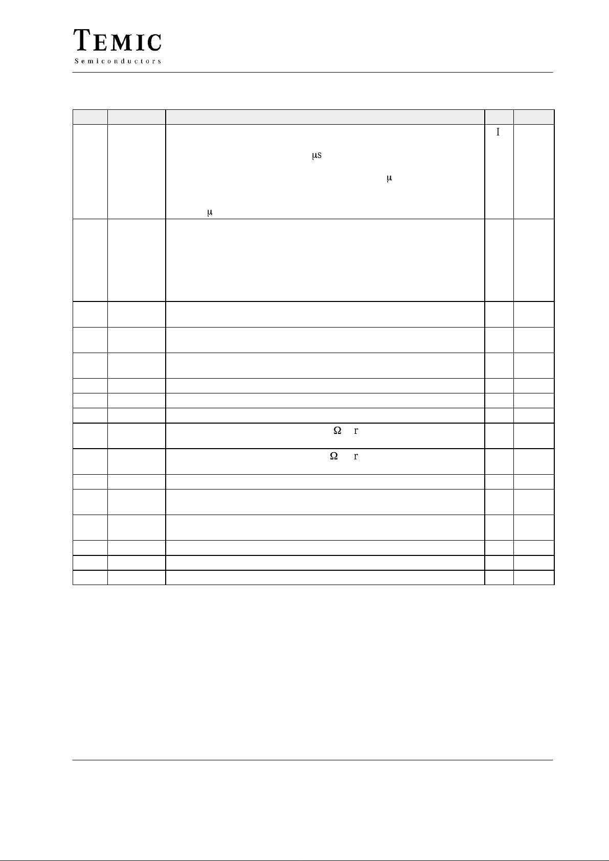
Pin Description TOIM3232
Pin Symbol Function I/Q Active
1 RESET Resets all internal registers. Initially must be HIGH (“1”) to reset internal
registers. When HIGH, the TOIM3232 sets the IrDA default bit rate of
9600 b/s, sets pulse width to 1.627 ms. Then the TOIM3232 enters the
power-saving mode. When RESET turns to LOW, the TOIM3232 exits
power-saving mode, and sets the baud rate and 1.627 ms pulse width
mode. In the application, the RESET pin can be controlled by either the
RTS or DTR line through RS232 level converter. Minimum hold time for
reset is 1 ms.
2 BR/D Baud Rate control / Data
When BR/D = 0, RD_232 data is transmitted to the IrDA transmitter pin
TD_IR, while RD_IR is routed to the transmitter pin TD_232.
When BR/D = 1, data received from the RS232 port is interpreted as the
control word. The control word programs the baud rate and pulse width of
TD_IR signal. The new baud rate and pulse width will be effective as
soon as BR/D returns to LOW.
3 RD_232 Data output of stretched signal to the RS232 port (using level converter);
received signal
4 TD_232 Data input from the RS232 port (passing the level converter); signal to be
transmitted
5 VCC_SD VCC shut-down output function. This pin can be used to shut down a
transceiver (e.g. TFDS3000). Output polarity: Inverted RESET input.
6 X1 Crystal input clock 3.6864 MHz I
7 X2 Crystal input clock I
8 GND Ground in common with the RS232 port and IrDA transceiver ground
9 TD_LED Transmit LED indicator driver. Use 270 W current limiting resistor in
series to LED to connect to V
10 RD_LED Receive LED indicator driver. Use 270 W current limiting resistor in
series to LED to connect to V
11 NC No connection
12 S1 User-programmable output. Can be used to turn a front end infrared trans-
ceiver ON/OFF (e.g. an infrared module at the adapter front).
13 S2 User-programmable output. Can be used to turn a front end infrared trans-
ceiver ON/OFF (e.g. an infrared module at the adapter back).
14 TD_IR Data output of shortened signal to the infrared transceiver TFDS3000 O HIGH
15 RD_IR Data input from the infrared transceiver TFDS3000 I LOW
16 V
CC
Supply voltage I
(VCC = 5 V).
CC
(VCC = 5 V).
CC
I HIGH
I
O HIGH
I HIGH
O LOW
O LOW
O LOW
O LOW
O LOW
TELEFUNKEN Semiconductors
Rev . A4, 26-Mar-96
3 (9)
Preliminary Information
 Loading...