

TEMIC TDA4483 Datasheet
TDA4483
Intercarrier Mixer and AM-Demodulator for TV and VCR
Features
D
D
Very high input sensitivity
D
Excellent signal-to-noise ratio
D
Intercarrier output signal gain controlled and independent from the picture carrier to sound carrier ratio
D
AM demodulator alignment free
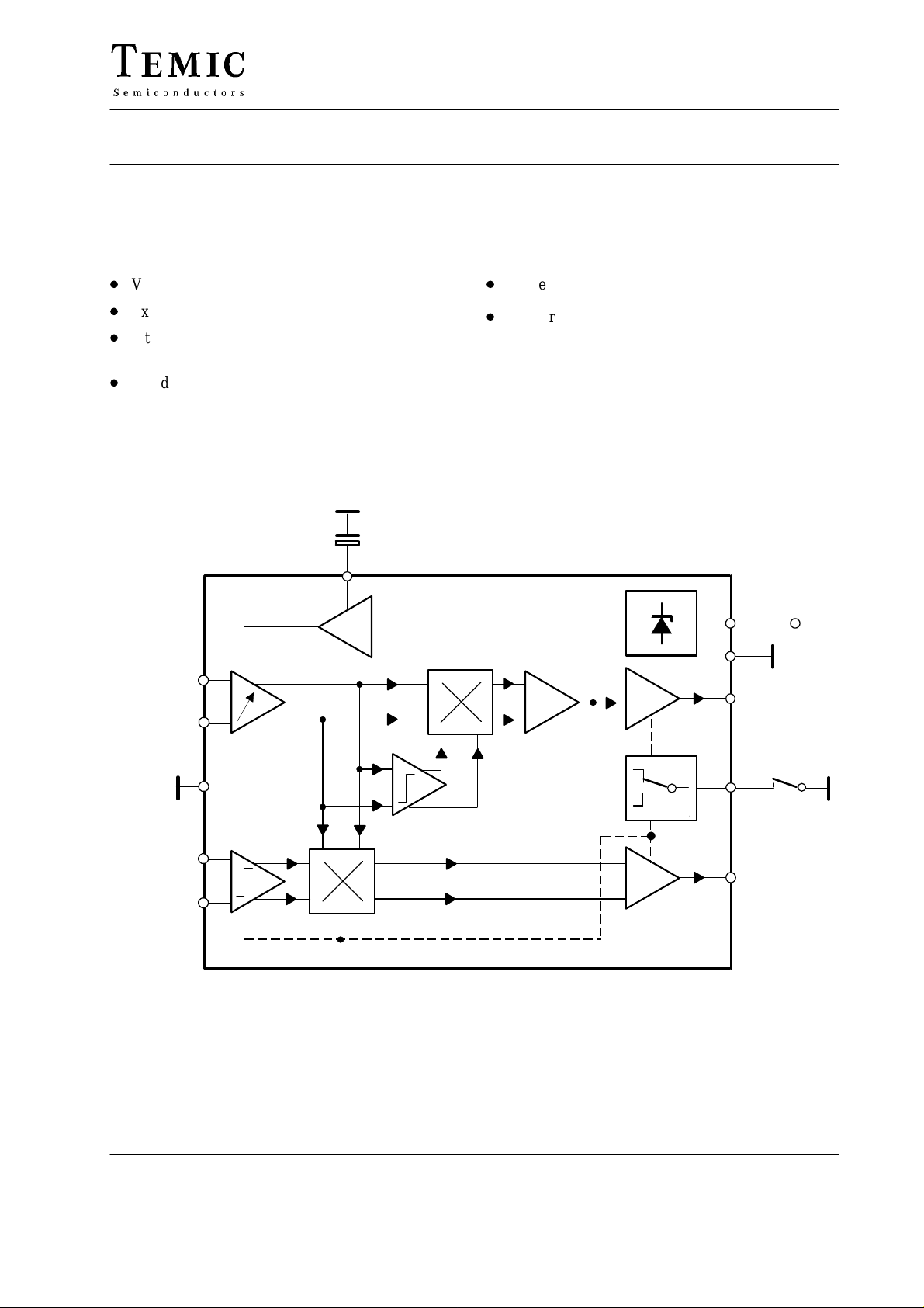
Block Diagram
Few external components
D
ESD protected
Case: DIP14
IF Input
sound carrier
IF Input
picture carrier
1
2
4
5
6
93 7481
AGC
7
Figure 1.
14
13
12
AF output
10
Standard switch
8
Intercarrier
output (FM)
(AM)
(AM / FM)
+V
S
TELEFUNKEN Semiconductors
Rev . A1, 15-May-96
1 (8)

TDA4483
Pin Description
Pin Function
1, 2 IF input (sound carrier)
3, 9, 11 No connected
4, 13 Ground
5, 6 IF input (picture carrier)
7 AGC time constant
8 Intercarrier output
10 Standard switch
12 AF output (AM)
14 Supply voltage
1
2
3
4
5
14
13
12
11
10
Circuit Description
The bipolar circuit TDA4483 enables high quality sound
IF processing for multistandard applications in TV-sets
and VCR. This circuit has separate inputs for the soundand picture carrier. The sound carrier signal (single or
dual carrier, modulated with AM, FM or NICAM) from
the SAW filter will be fed into a 3-stage, gain controlled,
IF amplifier (Pin 1 and 2).
The following two mixer stages operate using different
standards. In the case of AM, the first mixer works as a
quasi-synchronous detector providing the audio
frequency at Pin 12. Furthermore, the first mixer supplies
a regulation voltage to control the gain of the 3-stage IF
amplifier (AGC).
The second mixer stage works as a intercarrier mixer in
FM/NICAM mode and supplies the intercarrier signal at
Pin 8 (difference signal between picture and sound
carrier) independent of the picture carrier to sound carrier
ratio. In standard B/G the 5.5/5.74 MHz subcarrier is
6
7
available at Pin 8. The required picture carrier for the
intercarrier mixer will be coupled out from the tuned
demodulator circuit of the vision-IF IC (e.g. TDA4453 or
equivalent components). The selective and prelimited
picture carrier has to be applied symmetrically to the
picture carrier input (Pin 5 and Pin 6). An additional
limiting amplifier delivers the regenerated picture carrier
to the intercarrier mixer.
Possible modes of operation (FM/NICAM or AM) are
determined by the voltage level that is applied to Pin 10
(standard switch). Without external control voltage at
Pin 10, the FM/NICAM operation is automatically
selected. In the case of AM, the intercarrier output Pin 8
is switched off, however DC output voltage remains. In
corresponding with FM/NICAM operation, the AF output
Pin 12 is switched off.
9
8
2 (8)
TELEFUNKEN Semiconductors
Rev . A1, 15-May-96
TDA4483
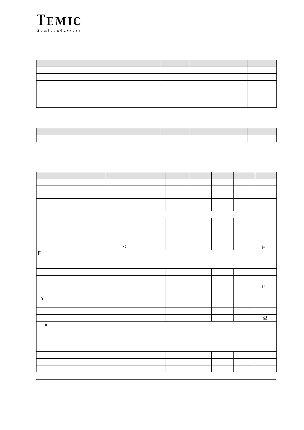
Absolute Maximum Ratings
Reference point Pin 13 (4), unless otherwise specified.
Parameters Symbol Value Unit
Supply voltage Pin 14 V
Supply current Pin 14 I
Power dissipation P
Junction temperature T
Operating temperature, ambient T
Storage temperature T
S
S
tot
j
amb
stg
Thermal Resistance
Parameters Symbol Value Unit
Junction-ambient R
thJA
Electrical Characteristics
T
= 25°C, VS = 12 V, reference point: Pin 13 (4), unless otherwise specified
amb
Parameters Test Conditions / Pins Symbol Min. T yp. Max. Unit
Supply voltage range Pin 14 V
Supply current FM-mode Pin 14
S
I
S
AM-mode
DC output voltage Pin 8
V
O
Pin 12
Standard switch Pin 10
Control voltage
Internal voltage FM-mode
AM-mode
FM-mode
Pin 10 open
V
CTRL
automatically selected
Control current V
CTRL
t
5 V Pin 10 I
CTRL
FM-mode
Test conditions: Picture carrier f
= 38.9 MHz, sound carrier f
PC
= 33.4 MHz, f
SC1
picture carrier to sound carriers ratio = 13/20 dB, picture carrier unmodulated (equivalent to sync peak pulse)
Sound carrier frequency range
Picture carrier input voltage Pin 5, 6
Sound carrier minimal
input voltage
5.5 MHz intercarrier
signal –3 dB Pin 1, 2
Sound carrier gain control
f
SC
v
PC
v
SC
AGC 60 65 dB
range
Intercarrier output voltage Pin 8
Output resistance Pin 8 R
v
OIC
O
Signal to noise ratio
Test conditions: Sound carrier V
= 10 mV, picture carrier v
SC
= 20 mV, limited carrier from TDA4453 or com-
PC
parable vision IF circuit, reference signal: frequency deviation ∆f = ±30 kHz, sound modulation f
Weighted (S + N)/N ratio of the demodulated intercarrier signal in accordance with CCIR468-4, measured with
FM-demodulator U2829B
Picture carrier unmodulated Channel 1/2 (S + N)/N 68/67 dB
Black picture Channel 1/2 (S + N)/N 62/60 dB
Grid Channel 1/2 (S + N)/N 50/48 dB
10 13.5 V
2.2
30 40 MHz
10 20 30 mV
13.5 V
50 mA
680 mW
125 °C
–25 to +70 °C
–25 to +125 °C
90 K/W
37
32
3.6
3.2
0
1.5
V
S
2.3
200
= 33.1587 MHz,
SC2
50
350 mV
15
= 1 kHz.
mod
mA
V
V
m
m
W
A
V
TELEFUNKEN Semiconductors
Rev . A1, 15-May-96
3 (8)
 Loading...