

INSTALLER/CONSUMER
CER TIF IED
D
E
S
I
G
N
C
E
R
T
I
F
I
E
D
SAFETY INFORMATION
PLEASE READ THIS MANUAL
BEFORE INSTALLING AND
USING APPLIANCE
WARNING!
IF THE INFORMATION IN THIS
MANUAL IS NOT FOLLOWED
EXACTLY, A FIRE OR
EXPLOSION MAY RESULT
CAUSING PROPERTY DAMAGE,
PERSONAL INJURY OR LOSS
OF LIFE.
FOR YOUR SAFETY
Installation and service must
be performed by a qualified
installer, service agency or the
gas supplier.
WHAT TO DO IF YOU SMELL GAS:
• Do not try to light any appliance.
• Do not touch any electric switch;
do not use any phone in your
building.
• Immediately call your gas
supplier from your neighbor’s
phone. Follow the gas suppliers
instructions.
• If you cannot reach your gas
supplier call the fire department.
DO NOT STORE OR USE
GASOLINE OR OTHER
FLAMMABLE VAPORS AND
LIQUIDS IN THE VICINITY OF
THIS OR ANY OTHER
APPLIANCE.
WARNING: Improper installation,
adjustment, alteration, service or
maintenance can cause injury or
property damage. Refer to this
manual. For assistance or additional
information, consult a qualified
installer, service agency or the gas
supplier.
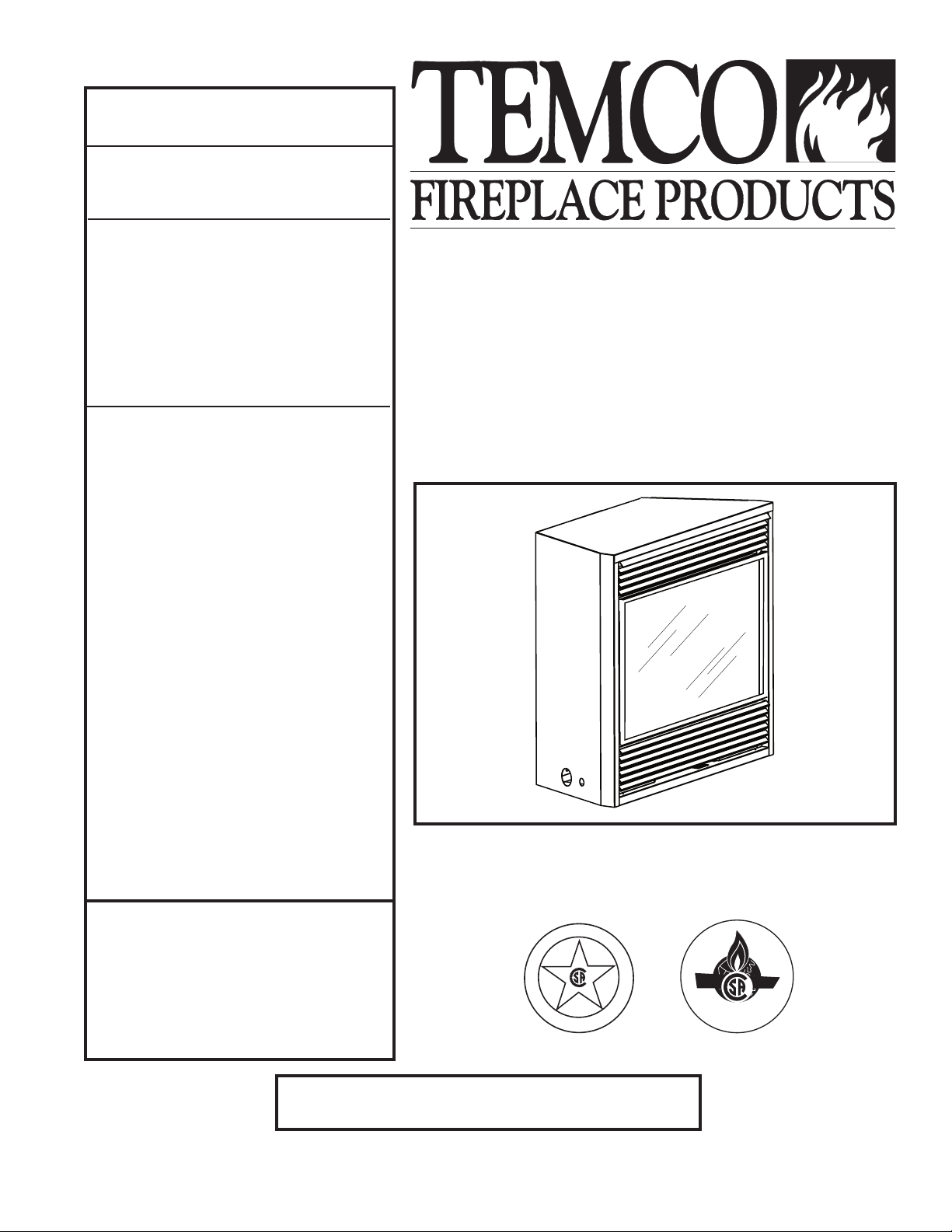
Builder Rear Vent Direct
Vent Zero Clearance Gas
Fireplace Heater
Models: 33RDVN, 36RDVN,
39RDVN
Installation Instructions and
Homeowner’s Manual
INSTALLER: Leave this manual with the appliance.
CONSUMER: Retain this manual for future reference.
20007628 5/08 Rev. 8

RDVN Series Direct Vent Gas Fireplace
Table of Contents
PLEASE READ THE INSTALLATION & OPERATING INSTRUCTIONS BEFORE USING THIS APPLIANCE.
Thank you and congratulations on your purchase of a CFM Corporation fireplace.
IMPORTANT: Read all instructions and warnings carefully before starting installation.
Failure to follow these instructions may result in a possible fire hazard and will void the warranty.
Installation & Operating Instructions
General Information, Warnings, Cautions ............................................................................................3
Requirements for the Commonwealth of Massachusetts ....................................................................4
Fireplace Dimensions ..........................................................................................................................
Locating Your Fireplace .......................................................................................................................6
Clearance to Combustibles .................................................................................................................
Mantels .............................................................................................................................................6
Hearth .............................................................................................................................................7
Framing & Finishing .............................................................................................................................
Final Finishing .....................................................................................................................................7
Gas Specifications ...............................................................................................................................
Gas Inlet and Manifold Pressures .......................................................................................................7
High Elevations ....................................................................................................................................7
Gas Line Installation ............................................................................................................................
Remote Switch Installation ..................................................................................................................8
Alternate Switch Location ....................................................................................................................
EB-1 Electrical Box ..............................................................................................................................9
General Venting Information
General Venting .................................................................................................................................
General Venting Information-Termination Location ..........................................................................11
General Information on Assembling Vent Pipes ................................................................................
Flex Vent Pipes ..................................................................................................................................12
Twist Lock Pipes ................................................................................................................................13
How to Use the Vent Graph ...............................................................................................................
Rear Wall Vent Application & Installation ...........................................................................................13
Vertical Sidewall Applications & Installation .......................................................................................
Below Grade Installations.. ................................................................................................................19
Vertical Through-the-Roof Applications & Installation ........................................................................20
Venting Components .........................................................................................................................
Operating Instructions
Glass Information ..............................................................................................................................
Louvre Removal ................................................................................................................................23
Window Frame Assembly Removal ...................................................................................................23
Glass Cleaning ..................................................................................................................................
Installation of Logs, Lava Rock & Ember Material ............................................................................24
Flame & Temperature Adjustment .....................................................................................................
Flame Characteristics ........................................................................................................................25
Lighting & Operating Instructions ......................................................................................................26
Troubleshooting .................................................................................................................................
Fuel Conversion Instructions .............................................................................................................30
Maintenance
Unit Adjustment .................................................................................................................................33
Maintenance ......................................................................................................................................33
Replacement Parts ........................................................................................................................................36
Optional Accessories
Fan Kits ...........................................................................................................................................
Wiring Instructions .............................................................................................................................39
Ceramic Refractory Kits .....................................................................................................................39
Decorative Bay Windows ...................................................................................................................39
Bay Window Screen ..........................................................................................................................40
Remote Controls ................................................................................................................................40
Warranty .........................................................................................................................................................44
Installation and Startup Checklist ...............................................................................................................45
Warranty Registration
...................................................................................................................................48
5
6
7
7
8
9
10
12
13
15
22
23
23
25
27
38
2
20007628
RDVN Series Direct Vent Gas Fireplace
�
Installation & Operating Instructions
This gas fireplace should be installed by a qualified installer,
preferably NFI or WETT (Canada) certified, in accordance with
local building codes and with current CSA-B149.1 Installation
codes for Gas Burning Appliances and Equipment. For USA
Installations follow local codes and/or the current National Fuel
Gas Code. ANSI Z223.1/NFPA 54.
FOR SAFE INSTALLATION AND OPERATION PLEASE NOTE
THE FOLLOWING:
1 . This fireplace gives off high temperatures and should be
located out of high traffic areas and away from furniture and
draperies.
2. Children and adults should be alerted to the hazards of the
high surface temperatures of this fireplace and should stay
away to avoid burns or ignition of clothing.
3. CAUTION: Due to high glass surface temperature chil-
dren should be carefully supervised when in the same
room as fireplace.
4. Under no circumstances should this fireplace be modified.
Parts removed for servicing should be replaced prior to
operating this fireplace again.
5. Installation and any repairs to this fireplace must be per
formed by a qualified installer, service agency or gas sup
plier. A professional service person should be contacted to
inspect the fireplace annually. More frequent cleaning may
be required due to excess lint and dust from carpeting, bedding material, etc.
6. Control compartments, burners and air passages in this fire
place should be kept clean and free of dust and lint. Make
sure that the gas valve and pilot light are turned off before
you attempt to clean this fireplace.
7. The venting system (chimney) of this fireplace should be
checked at least once a year and if needed your venting
system should be cleaned.
8. Keep the area around your fireplace clear of combustible
materials, gasoline and other flammable vapour and liquids.
This fireplace should not be used as a dry-ing rack for cloth
ing, nor should Christmas stockings or decorations be hung
on or around the fireplace.
9. Under no circumstances should any solid fuels (wood, coal,
paper or cardboard etc.) be used in this fireplace.
10. The flow of combustion and ventilation air must not be ob
structed in any way.
11. When the fireplace is installed directly on carpeting, vinyl tile
or any combustible material other than wood, this fireplace
must be installed on a metal or wood panel extending the
full width and depth of the fireplace.
12. This fireplace requires adequate ventilation and combustion
air to operate properly.
-
-
-
13. This fireplace must not be connected to a chimney flue
serving a separate solid fuel burning fireplace.
14. When the fireplace is not in use it is recommended that the
gas control valve be left in the OFF position.
15. These units have been approved for bedroom use.
33RDVN / 36RDVN / 39RDVN
Certified To
ANSI Z21.88-2005 / CSA 2.33-2005 / UL307B
Vented Gas Fireplace Heaters
WARNING: Check with your electronics manufacturer
before installing a television or other electronic device above this fireplace.
This appliance may be installed in an aftermarket
permanently located, manufactured home or mobile
home, where not prohibited by local codes.
This appliance is only for use with the type of gas
indicated on the rating plate. This appliance is not
convertible for use with other gases, unless a certified
kit is used.
IMPORTANT:
PLEASE REVIEW THE FOLLOWING CAREFULLY
Remove any plastic from from parts before turning the fireplace ON.
It is normal for fireplaces fabricated of steel to give off some
expansion and/or contraction noises during the start up or
cool down cycle. Similar noises are found with your furnace
heat exchanger or car engine.
It is not unusual for your gas fireplace to give off some odor
the first time it is burned. This is due to the curing of the paint
and any undetected oil from the manufacturing process.
Please ensure that your room is well ventilated-open all
windows.
It is recommended that you burn your fireplace for at least ten
four (4) hours the first time you use it. If the optional fan kit
has been installed, place the fan switch in the “OFF” position
during this time.
Proposition 65 Warning: Fuels used in gas, woodburning or oil fired appliances, and the products of
combustion of such fuels, contain chemicals known to
-
the State of California to cause cancer, birth defects
and other reproductive harm.
California Health & Safety Code Sec. 25249.6
20007628
3

RDVN Series Direct Vent Gas Fireplace
Installation & Operating Instructions
Requirements for the Commonwealth of
Massachusetts
All gas fitting and installation of this heater shall only be
done by a licensed gas fitter or licensed plumber.
For all side wall horizontally vented gas fueled
equipment installed in every dwelling, building or
structure used in whole or in part for residential
purposes, including those owned or operated by the
Commonwealth and where the side wall exhaust vent
termination is less than seven (7) feet above finished
grade in the area of the venting, including but not limited
to decks and porches, the following requirements shall
be satisfied:
Installation of Carbon Monoxide Detectors
At the time of installation of the side wall horizontal
vented gas fueled equipment, the installing plumber
or gas fitter shall observe that a hard wired carbon
monoxide detector with an alarm is installed on each
additional level of the dwelling, building or structure
served by the side wall horizontally vented gas fueled
equipment. It shall be the responsibility of the property
owner to secure the services of qualified licensed
professionals for the installation of hard wired carbon
monoxide detectors.
In the event that the side wall horizontally vented gas
fueled equipment is installed in a crawl space or an
attic, the hard wired carbon monoxide detector with
alarm and battery back-up may be installed on the next
adjacent floor level.
In the event that the requirements of this subdivision
can not be met at the time of completion of installation,
the owner shall have a period of thirty (30) days
to comply with the above requirements; provided,
however, that during said thirty (30) day period, a
battery operated carbon monoxide detector with an
alarm shall be installed.
Approved Carbon Monoxide Detectors
Each carbon monoxide detector as required in
accordance with the above provisions shall comply with
NFPA 720 and ANSI/UL 2034 listed and IAS certified.
Signage
A metal or plastic identification plate shall be
permanently mounted to the exterior of the building at
a minimum height of eight (8) feet above grade directly
in line with the exhaust vent terminal for the horizontally
vented gas fueled heating appliance or equipment. The
sign shall read, in print size no less than one-half (1/2)
inch in size, “GAS VENT DIRECTLY BELOW, KEEP
CLEAR OF ALL OBSTRUCTIONS”.
Inspection
The state or local gas inspector of the side wall
horizontally vented gas fueled equipment shall not
approve the installation unless, upon inspection, the
inspector observes carbon monoxide detectors and
signage installed in accordance with the provisions of
248 CMR 5.08(2)(a)1 through 4.
Exemptions
The following equipment is exempt from 248 CMR
5.08(2)(a)1 through 4:
• The equipment listed in Chapter 10 entitled
“Equipment Not Required To Be Vented” in the most
current edition of NFPA 54 as adopted by the Board;
and
• Product Approved side wall horizontally vented gas
fueled equipment installed in a room or structure
separate from the dwelling, building or structure
used in whole or in part for residential purposes.
MANUFACTURER REQUIREMENTS
Gas Equipment Venting System Provided
When the manufacturer of Product Approved side
wall horizontally vented gas equipment provides a
venting system design or venting system components
with the equipment, the instructions provided by the
manufacturer for installation of the equipment and the
venting system shall include:
• Detailed instructions for the installation of the venting
system design or the venting system components;
and
• A complete parts list for the venting system design or
venting system.
Gas Equipment Venting System NOT Provided
When the manufacturer of a Product Approved side
wall horizontally vented gas fueled equipment does
not provide the parts for venting the flue gases, but
identifies “special venting systems”, the following
requirements shall be satisfied by the manufacturer:
• The referenced “special venting system” instructions
shall be included with the appliance or equipment
installation instructions; and
• The “special venting systems” shall be Product
Approved by the Board, and the instructions for
that system shall include a parts list and detailed
installation instructions.
A copy of all installation instructions for all Product
Approved side wall horizontally vented gas fueled
equipment, all venting instructions, all parts lists
for venting instructions, and/or all venting design
instructions shall remain with the appliance or
equipment at the completion of the installation.
4
20007628
RDVN Series Direct Vent Gas Fireplace
F
O - Rough Opening Width
Rough
Opening
Height
Rough
Opening
Depth
S
S
R
Q
P
E
I
H
J
D
A
C
N
B
K
L
G
M
J
Gas Line
Access
Gas Line
Access
Low
Voltage
Electrical
Access
Electrical
Access
C
L
Centerline of
7" Collar
Fireplace Dimensions
7628
Fig. 1 Fireplace specifications and framing dimensions.
Ref. 33RDVN 36RDVN 39RDVN
A 33” (838 mm) 36” (914 mm) 39” (991 mm)
B 28
⁷⁄₈” (733 mm) 34¹⁄₄” (870 mm) 34¹⁄₄” (870 mm)
C 31” (787 mm) 33” (838 mm) 36” (914 mm)
D 16
³⁄₈” (416 mm) 21” (533 mm) 21” (533 mm)
E 22” (559 mm) 24” (610 mm) 24” (610 mm)
F 11
G 14
H 20
I 23
J 5” (127 mm) 6
K 7
L 8
M 1
Framing Dimensions
N 29” (737 mm) 35” (889 mm) 35” (889 mm)
O 33
P 12” (305 mm) 16
Q 51” (1295 mm) 58
R 25
S 36” (914 mm) 41
¹⁄₂” (292 mm) 16” (406 mm) 16” (406 mm)
³⁄₄” (375 mm) 19” (483 mm) 19” (483 mm)
¹⁄₄” (515 mm) 23⁷⁄₈” (606 mm) 23⁷⁄₈” (606 mm)
³⁄₄” (603 mm) 27¹⁄₂” (699 mm) 27³⁄₈” (695 mm)
³⁄₄” (171 mm) 6¹⁄₄” (159 mm)
¹⁄₂” (191 mm) 10” (254 mm) 8³⁄₈” (213 mm)
¹⁄₂” (216 mm) 13¹⁄₂” (343 mm) 12¹⁄₂” (318 mm)
⁷⁄₈” (18 mm) 1⁷⁄₈” (18 mm) 1⁷⁄₈” (18 mm)
¹⁄₂” (851 mm) 36¹⁄₂” (927 mm) 39¹⁄₂” (1003 mm)
¹⁄₂” (419 mm) 16¹⁄₂” (419 mm)
⁷⁄₈“ (1495 mm) 62¹⁄₄” (1581 mm)
¹⁄₂” (648 mm) 29⁷⁄₈” (748 mm) 31¹⁄₈” (790 mm)
⁵⁄₈” (1057 mm) 44” (1118 mm)
20007628
5
RDVN Series Direct Vent Gas Fireplace
Y
E
A
B
C
D
F
Y
B
X
X
A B C D E
V
W
X
Y
Z
Fireplace
J
F
G
H
I
Mantel
Leg
O
N
M
L
K
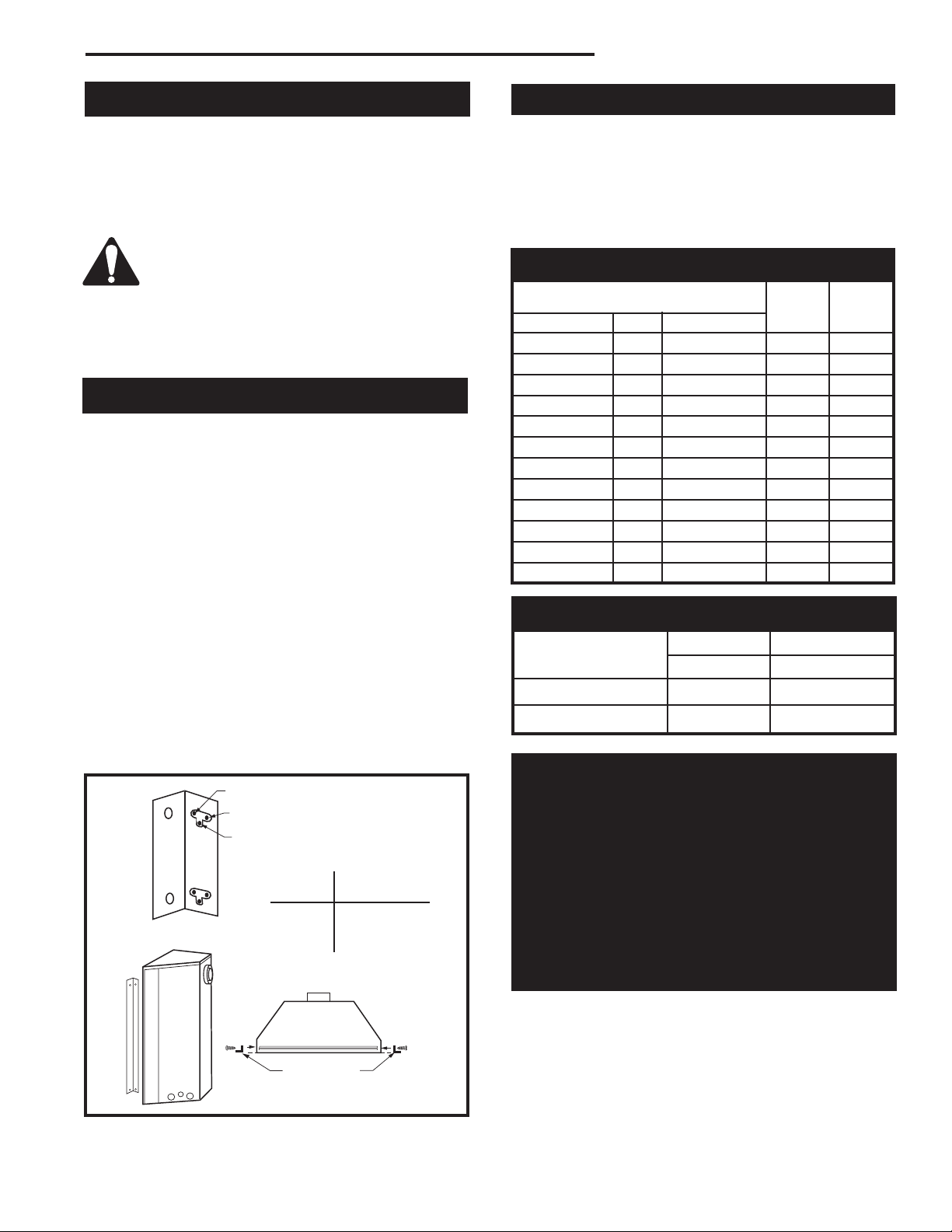
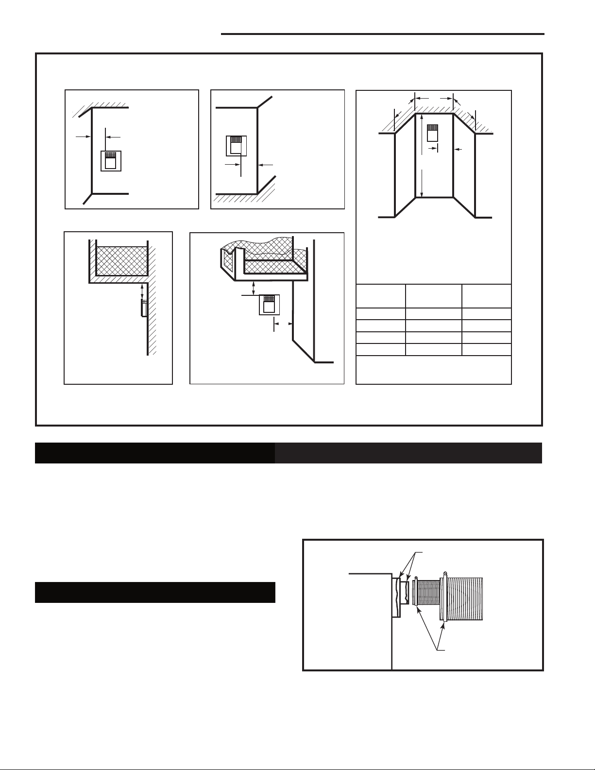
Locating Your Fireplace
LU584-T
Fig. 2 Locate gas fireplace.
A - Flat on wall B - Cross corner C - **Island
D - Room divider E - Flat on wall corner F - Chase installation
Y - Refer to “Clearance to Combustibles” Section
Note (Fig. 2):
** Island (C) and Room Divider (D) installation is possible as
long as the horizontal portion of the vent system (X) does not
exceed 20’ (6m). See details in manual Venting Section.
Clearance to Combustibles
Top of Unit to Ceiling ............................... 36” (914 mm)
Front of Unit to Combustibles .................. 36” (914 mm)
Appliance
Top .......................................................... 0” (0 mm)
Bottom ..................................................... 0” (0 mm)
Side ......................................................... 0” (0 mm)
Back ........................................................ 0” (0 mm)
Venting
Concentric sections of DV Vent
Top, bottom & sides .............................. 1” (25 mm)
Rear Vent Applications
Top ........................................................ 2” (51 mm)
Sides and Bottom .................................. 1” (25 mm)
Flex Vent .................................................. 7/8” (22 mm)
Top Louvre
Assembly
Top of Combustion
Chamber
Bottom of Door Trim
CFM146
Mantel Chart
Mantel Shelf Mantel from Top
Ref. or Breast Plate Ref. of Combustion Chamber
Depth 36/39/RDVN 33RDVN
V 10” (254 mm) A 19” (483 mm) 17” (432 mm)
W 8” (203 mm) B 17” (432 mm) 15” (381 mm)
X 6” (152 mm) C 15” (381 mm) 13” (330 mm)
Y 4” (101 mm) D 13” (330 mm) 11” (279 mm)
Z 2” (50 mm) E 11” (279 mm) 9” (229 mm)
Fig. 3a Combustible mantel minimum installation.
Black
Surround
Face
Side of
Combustion Chamber
Mantels
The height that a combustible mantel is fitted above the
fireplace is dependent on the depth of the mantel. This
also applies to the distance between the mantel leg (if
fitted) and the fireplace.
For the correct mounting height and widths refer to
Figures 3a and 3b.
The fitting of a bay window trim kit does not effect
the distances and reference points referred to in the
diagram and chart.
Noncombustible mantels and legs may be installed at
any height and width around the appliance.
When using paint or lacquer to finish the mantel, such
paint or lacquer must be heat resistant to prevent
discoloration.
6
CFM170
Mantel Mantel Leg from Side
Ref. Leg Depth Ref. of Comb. Opening
F 10” (254 mm) K 11¹⁄₂” (292 mm)
G 8” (203 mm) L 9¹⁄₂” (241 mm)
H 6” (152 mm) M 7¹⁄₂” (191 mm)
I 4” (101 mm) N 5¹⁄₂” (140 mm)
J 2” (51 mm) O 3¹⁄₂” (89 mm)
Fig. 3b Combustible mantel leg minimum installation.
20007628
RDVN Series Direct Vent Gas Fireplace
C
A
B
Hearth
A hearth is not mandatory but is recommended for
aesthetic purposes. We recommend a noncombustible
hearth which projects out 12” (305 mm) or more from
the front of the fireplace.
Cold climate installation recommendation:
When installing this unit against a
non-insulated exterior wall or chase,
it is mandatory that the outer walls
be insulated to conform to applicable
insulation codes.
NOTE: Never allow vapor barrier to contact the
outer casing of this fireplace or venting.
Framing and Finishing
1. Choose the unit location.
2. Place the unit into position and secure it to the floor
with 1¹⁄₂” (38 mm) screws, or nails. The holes to
secure the unit to the floor are located just behind
the access door grille on the left and right side of the
unit.
3. Frame in the fireplace with a header across the top.
It is important to allow for the finished wall face when
setting the depth of the frame.
4. Attach the fireplace to the frame using the adjust
able frame drywall strips (located behind the access
door for shipping). Preset the depth to suit the facing
material of the wall. The strips are adjustable to 1/2”
(13 mm), 5/8” (16 mm) or 3/4” (19 mm). (Fig. 4)
5. Screw through the slotted holes in the drywall strip
and into the pre-drilled holes in the fireplace side.
Measure from the face of the fireplace to the face of
the drywall strip to confirm the final depth.
-
Final Finishing
Noncombustible materials such as brick or tile may be
extended over the edges of the face of the appliance.
DO NOT cover any vent or grille panels.
If a Trim Kit is going to be installed on the fireplace, the
brick or tile will have to be installed flush with the edges
of the appliance.
Gas Specifications
Max. Min.
Input Input
Model Fuel Gas Control BTU/h BTU/h
33RDVN Nat Millivolt 18,000 13,000
33RDVP Prop Millivolt 18,000 13,000
33RDVDSN Nat 120 V 18,000 n/a
33RDVDSP Prop 120 V 18,000 n/a
36RDVN Nat Millivolt 20,000 13,000
36RDVP Prop Millivolt 20,000 13,000
36RDVDSN Nat 120 V 20,000 n/a
36RDVDSP Prop 120 V 20,000 n/a
39RDVN Nat Millivolt 22,000 15,000
39RDVP Prop Millivolt 22,000 15,000
39RDVDSN Nat 120 V 22,000 n/a
39RDVDSP Prop 120 V 22,000 n/a
Gas Inlet and Manifold Pressures
Natural LP (Propane)
Inlet Minimum 4.5” w.c. 10.8” w.c.
Inlet Maximum 14.0” w.c. 14.0” w.c.
Manifold Pressure 3.5” w.c. 10.0” w.c.
High Elevations
Fig. 4 Nailing flanges.
20007628
Adjustable Drywall Strip
(Nailing Flange)
Screw Drywall
Position Depths
A 1/2” / 13mm
B 5/8” / 16mm
C 3/4” / 19mm
Adjustable
1/2”, 5/8” &
3/4” Spacing
Input ratings are shown in BTU per hour and are
certified without deration for elevations up to
4,500 feet (1,370 m) above sea level.
For elevations above 4,500 feet (1,370 m) in USA,
installations must be in accordance with the current ANSI Z223.1/NFPA 54 and/or local codes having jurisdiction.
In Canada, please consult provincial and/or local
authorities having jurisdiction for installations at
elevations above 4,500 feet (1,370 m).
FP1023
7
RDVN Series Direct Vent Gas Fireplace
Gas Line Installation
When purging gas line, the front window
frame assembly must be removed.
1. The gas pipeline can be brought in through the rear
of the fireplace as well as the bottom. Knockouts are
provided on the bottom behind the valve to allow for
the gas pipe installation and testing of any gas connection. It is most convenient to bring the gas line in
from the rear right side of the valve as this allows fan
installation or removal without disconnecting the gas
line.
The gas line connection can be made with properly
tinned 3/8” copper tubing, 3/8” rigid pipe or an approved flex connector. Since some municipalities
have additional local codes, it is always best to con
sult your local authority and the National Fuel Gas
Code, ANSI Z223.1/NFPA 54 in the USA or the CSAB149.1 installation codes.
*Adhere to the following installation requirements in the State
of Massachusetts:
• The installer must be a licensed plumber or gas fitter.
• Flex connectors must be Massachusetts approved, cannot
exceed 36” (914mm) in length, must be a minimum 1/2”
dia. and may not penetrate a wall.
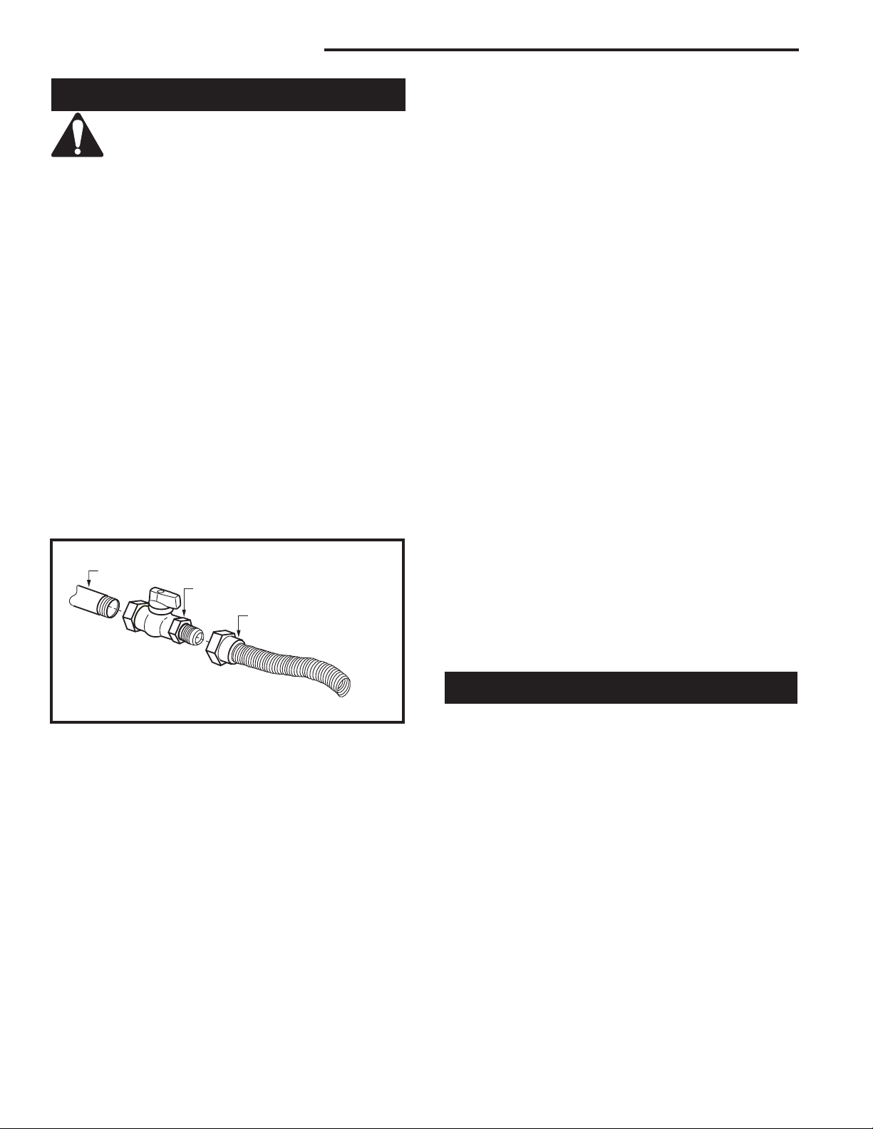
1/2” Gas Supply
1/2” NPT X 1/2” Flare Shut-off Valve
3/8” Flex line
(from valve)
5. For natural gas, a minimum of 3/8” iron pipe with a
gas supply pressure of 4.5” w.c. (from the gas meter). Consult with local gas utility and ANSI Z223.1/
NFPA 54 if any questions arise concerning pipe
sizes.
6. Turn the gas supply to ‘ON’ and check for leaks. DO
NOT USE OPEN FLAME FOR THIS PURPOSE.
Use an approved leak testing solution.
7. The appliance and its appliance main gas valve
must be disconnected from the gas supply piping
system during any pressure testing of that system at
test pressures in excess of 1/2 psig (3.5KPa).
8. This appliance must be isolated from the gas supply
piping system by closing its equipment shut off valve
during any pressure testing of the gas supply piping
system at test pressures equal to 1/2 psig (3.5KPa).
Always check for gas leaks with a mild soap and
water solution. Do not use an open flame for leak
testing.
The gas control is equipped with a captured screw type
pressure test point, therefore it is not necessary to provide a 1/8” test point up stream of the control.
When using copper or flex connector use only approved
fittings. Always provide a union when using black iron
pipe so that the gas line can be easily disconnected for
burner or fan servicing. Refer to the gas specifications
for pressure details and ratings.
The fireplace valve must not be subjected to any test
pressures exceeding 1/2 psi. Isolate or disconnect this
or any other gas appliance control from the gas line
when pressure testing.
FP297A
Fig. 5 Typical gas supply installation.
2. The gas control inlet is 3/8” NPT typical installation
layout for rigid pipe is shown in Figure 5.
NOTE: All models are equipped with a flex tube
with a shut off valve having a 1/2” NPT inlet. The
flex line with shut off is shipped in the control
valve compartment. Using two wrenches, tighten
the flexible tube at the shut off valve and at the
gas control
3. When using a flex connector,* use only approved fit
tings. When a union is installed, provide easy access
in its placement for servicing. Refer to gas specification for pressure details and ratings.
4. When a vertical section of gas pipe is required for
the installation, a condensation trap is needed. In
Canada see CSA-B149.1 for code details. See the
National Fuel Gas Code ANSI Z223.1/NFPA 54 in
the USA.
8
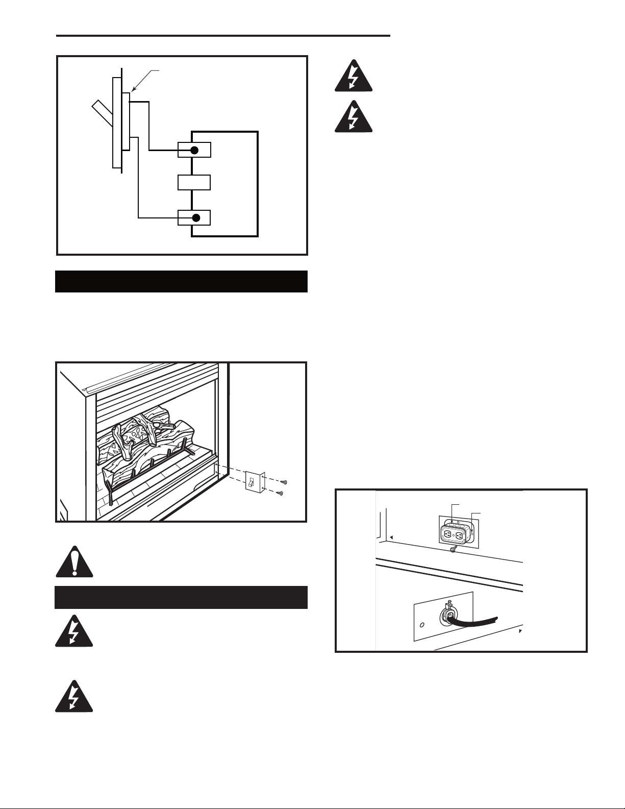
Remote ON/OFF Switch
Installation:
1. Thread the wiring through holes on the end panels
of appliance. Take care not to cut wire or insulation
on metal edges. Route the wire to a conveniently
located receptacle box.
2. Attach the wire to the ON/OFF switch and install the
switch into the receptacle box.
3. Connect the other ends of the wire to the gas control
valve. (Fig. 6)
-
20007628
RDVN Series Direct Vent Gas Fireplace
OUTSIDE
FRONT OF UNIT
INSIDE
FRONT OF UNIT
TP
TH
TP
TH
Remote ON/OFF
Switch or Thermostat or
Remote Control
Gas
Control
Valve
FP1224
Fig. 6 Remote switch wiring diagram.
Alternate Switch Location
The remote switch can be installed on the front/side of
the access door. Simply mount the switch to the bracket
provided and screw the bracket to either side of the
frame, lining up the screws with the pre-punched holes.
(Fig. 7)
It is strongly suggested that the wiring of
the EB-1 Electrical Junction Box be carried
out by a licensed electrician.
Ensure that the power to the supply line
has been disconnected before commencing this procedure.
The EB-1 Electrical junction box has been fitted standard on this model to allow for the easy connection of an
optional fan kit.
To connect the EB-1 box to the house electrical supply
follow the steps below.
1. Unscrew retaining screw from EB-1 base plate (Fig.
8) and remove the EB-1 assembly from the appliance.
2. Remove the front cover of the EB box.
3. Remove the plug socket assembly from the EB-1
box.
4. Feed the supply line in through the EB-1 opening in
the side of the appliance and then through the back
of the EB-1 assembly. (Fig. 8)
5. Connect the black wire of the power supply line to
the brass screw (polarized) of the socket assembly.
6. Connect the white wire of the power line to the
chrome screw of the socket assembly.
7. Connect the ground wire of the supply line to the
green screw of the socket assembly.
8. Refit the socket assembly back into the electrical
box and replace the cover plate. Secure the cable
with the clamp on the outside of the EB-1 base
plate and refit the EB-1 assembly to the unit with the
screw removed in step 1.
Fig. 7 Alternate switch location.
Do not wire the remote ON/OFF wall
switch for the gas fireplace to the 120 volt
power supply.
EB-1 Electrical Box
The fireplace, when installed, must be
electrically connected and grounded in
accordance with local codes or, in the absence of local codes, with the current CSA
C22.1 Canadian Electrical Code.
For USA installations follow local codes
and the national electrical code ANSI/
NFPA No. 70.
20007628
T256
Electrical Box
Retaining Screw
FP580
Fig. 8 EB-1 receptacle.
9

RDVN Series Direct Vent Gas Fireplace
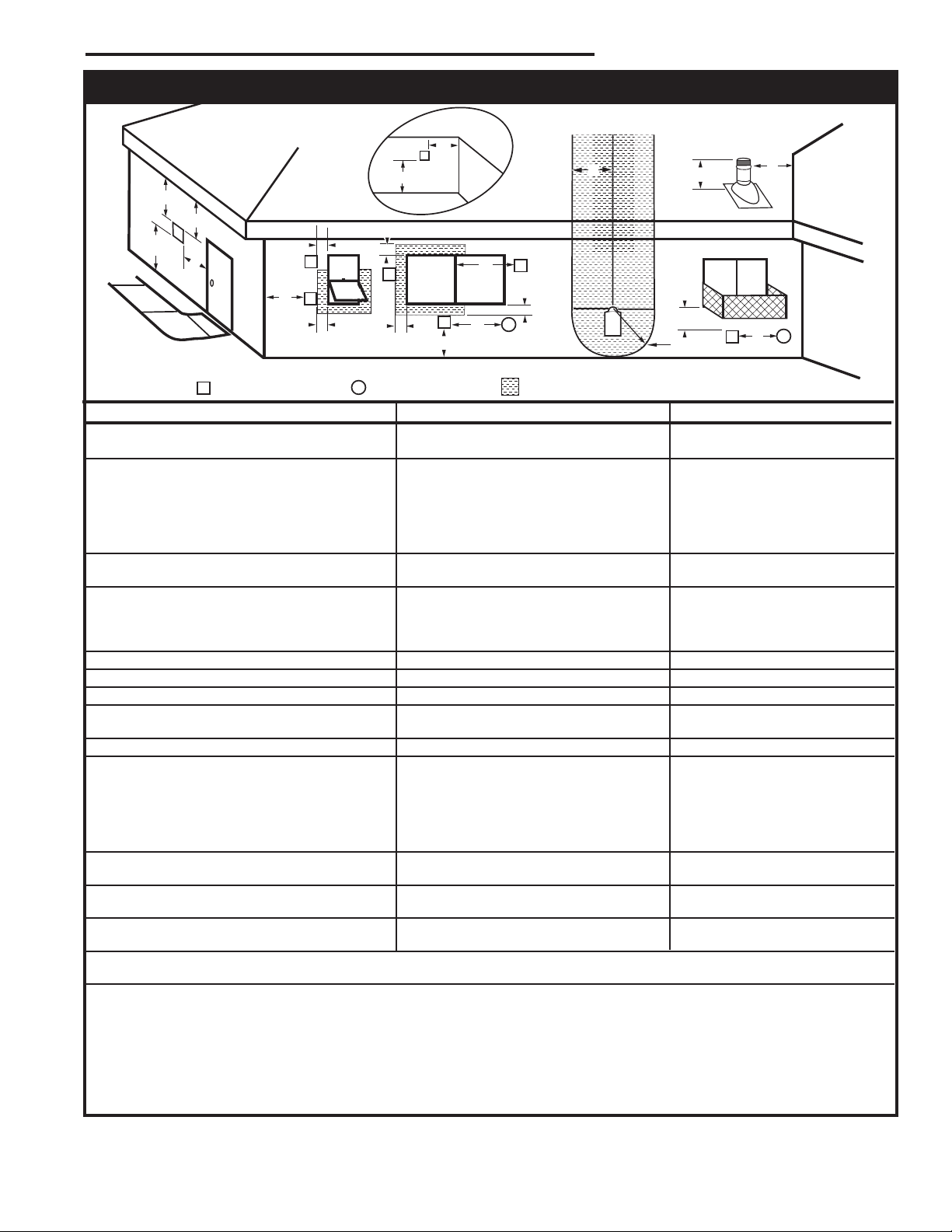
General Venting
Your fireplace is approved to be vented either through
the side wall, or vertical through the roof.
• Only CFM Corporation venting components specifically approved and labelled for this fireplace
may be used.
• Venting terminals shall not be recessed into a wall or
siding.
• Horizontal venting which incorporates the twist lock
pipe must be installed on a level plane without an
inclining or declining slope.
• Horizontal venting which incorporates the use of flex
venting shall have an inclining slope from the unit of
1” (25 mm) per 24” (610 mm).
There must not be any obstruction such as bushes,
garden sheds, fences, decks or utility buildings within
24” from the front of the termination hood.
Do not locate termination hood where excessive snow
or ice build up may occur. Be sure to check vent termination area after snow falls, and clear to prevent accidental blockage of venting system. When using snow
blowers, make sure snow is not directed towards vent
termination area.
Location of Vent Termination
It is imperative the vent termination be located observing the minimum clearances as shown on the following
page.
10
20007628
RDVN Series Direct Vent Gas Fireplace
V
V
V
V
V
V
V
X
X
X
D
E
B
B
B
C
B
M
B
A
J
K
F
L
VENT TERMINATION AIR SUPPLY INLET
AREA WHERE TERMINAL IS NOT PERMITTED
H
I
Operable
Operable
Fixed
Closed
V
B
INSIDE
CORNER DETAIL
V
A
G
N
N
CFM145a
General Venting Information - Termination Location
Canadian Installations1 US Installations
A = Clearance above grade, veranda, porch, 12” (30cm) 12” (30cm)
deck, or balcony
B = Clearance to window or door that may be 6” (15cm) for appliances 6” (15cm) for appliances
opened < 10,000Btuh (3kW), 12” (30cm) < 10,000 Btuh (3kW), 9”
for appliances > 10,000 Btuh (3kW) and (23cm) for appliances > 10,000
< 100,000 Btuh (30kW), 36” (91cm) Btuh (3kW) and < 50,000 Btuh
for appliances > 100,000 Btuh (30kW) (15kW), 12” (30cm) for
appliances > 50,000 Btuh (15kW)
C = Clearance to permanently closed window 12” (305mm) recommended to 12” (305mm) recommended to
prevent window condensation prevent window condensation
D = Vertical clearance to ventilated soffit located
above the terminal within a horizontal 18” (458mm) 18” (458mm)
distance of 2 feet (610mm) from the center
line of the terminal
E = Clearance to unventilated soffit 12” (305mm) 12” (305mm)
F = Clearance to outside corner see next page see next page
G = Clearance to inside corner (see next page) see next page see next page
H = Clearance to each inside of center line 3’ (91cm) within a height of 15’ 3’ (91cm) within a height of 15’
extended above meter/regulator assembly above the meter/regulator assembly above the meter/regulator assy
I = Clearance to service regulator vent outlet 3’ (91cm) 3’ (91cm)
J = Clearance to nonmechanical air supply inlet 6” (15cm) for appliances < 10,000 6” (15cm) for appliances
to building or the combustion air inlet to any Btuh (3kW), 12” (30cm) for < 10,000 Btuh (3kW), 9”
other appliances appliances > 10,000 Btuh (3kW) and < (23cm) for appliances > 10,000
100,000 Btuh (30kW), 36” (91cm) Btuh (3kW) and < 50,000 Btuh
for appliances > 100,000 Btuh (30kW) (15kW), 12” (30cm) for
appliances > 50,000 Btuh (15kW)
K = Clearance to a mechanical air supply inlet 6’ (1.83m) 3’ (91cm) above if within 10’
(3m) horizontally
L = Clearance above paved sidewalk or paved 7’ (2.13m)† 7’ (2.13m)†
driveway located on public property
M = Clearance under veranda, porch, deck or 12” (30cm)‡ 12” (30cm)‡
balcony
N = Clearance above a roof shall extend a minimum of 24” (610mm) above the highest point when it passes through the roof
surface, and any other obstruction within a horizontal distance of 18” (450mm).
1 In accordance with the current CSA-B149 Installation Codes
2 In accordance with the current ANSI Z223.1/NFPA 54 National Fuel Gas Codes
† A vent shall not terminate directly above a sidewalk or paved driveway which is located between two single family dwellings and serves both dwell ings
‡ only permitted if veranda, porch, deck or balcony is fully open on a minimum 2 sides beneath the floor:
NOTE: 1. Local codes or regulations may require different clearances.
2. The special venting system used on Direct Vent Fireplaces are certified as part of the appliance, with clearances tested and approved by the
listing agency.
3. CFM Corporation assumes no responsibility for the improper performance of the appliance when the venting system does not
meet these requirements.
Fig. 9 Vent termination clearances.
20007628
2
11
RDVN Series Direct Vent Gas Fireplace
Outside Corner
Inside Corner
Termination Clearances
Termination clearances for buildings with combustible and noncombustible exteriors.
G =
Combustible
6" (152 mm)
Noncombustible
2" (51 mm)
F =
Combustible
6" (152 mm)
Noncombustible
2" (51 mm)
G
Balcony with no side wall
M =
Combustible &
Noncombustible
12" (305 mm)
M
Balcony with perpendicular side wall
M = 24" (610 mm)
P = 20” (508 mm)
M
F
Alcove Applications*
C
D
C
E
V
V
Combustible &
Noncombustible
V
V
V
E = Min. 6” (152 mm) for
non-vinyl sidewalls
Min. 12” (305 mm) for
vinyl sidewalls
O = 8’ (2.4 m) Min.
O
P
*NOTE: Termination in an alcove space (spaces open only on one side and with an overhang) is permitted with the dimensions
specified for vinyl or non-vinyl siding and soffits. 1. There must be a 3’ (914 mm) minimum between termination caps. 2. All
mechanical air intakes within 10’ (1 m) of a termination cap must be a minimum of 3’ (914 mm) below the termination cap. 3. All
gravity air intakes within 3’ (914 mm) of a termination cap must be a minimum of 1’ (305 mm) below the termination cap.
Fig. 9 Termination clearances.
Canadian Installations:
The venting system must be installed in accordance
with the current CSA-B149 .1 installation code.
USA Installations:
The venting system must conform with local codes and/
or the current National Fuel Gas code ANSI Z223.1/
NFPA 54.
General Information on Assembling Vent Pipes
* Be sure the vent is actually crushed before proceeding. Apply a tug to be sure the vent will not slip off the
collars.
Repeat process with 7” flex vent pipe. The same procedure must be performed on the vent side.
Only venting components manufactured by CFM Corporation can be used in Direct Vent systems.
Flex Vent Pipes
Before joining the flex vent pipe to the unit, apply a
bead of high temperature sealant* (provided) to the 4”
pipe exiting the fireplace. Secure flex vent pipe in place
with a hose clamp (provided).
*Be sure the flex pipe overlaps at least 1” (25 mm) onto
the collars of the fireplace and termination. If the termination has an internal bead, be sure to overlap and
secure 1” (25 mm) past the bead.
12
Fig. 10 Apply high temperature sealant to 4” and 7” pipes.
No.
of Caps D
1 3’ (914 mm) 2 x D
2 6’ (1.8 m) 1 x D
3 9’ (2.7 m) 2/3 x D
4 12’ (3.7 m) 1/2 x D
D
= # of Termination caps x 3
Min.
C
= (2 / # termination caps) x D
Max.
Min.
Hose Clamp
C
Apply High Temperature
Sealant
Max.
Actual
Actual
Actual
Actual
Actual
584-15
FP1471
20007628
Twist Lock Pipes
3
4
5
6
7
8
9
10
11
12
13
14
15
16
17
18
19
20
21
22
23
24
25
26
27
28
29
30
3 4 5 6 7 8 9 10 11 12 13 14 15 16 17 18 19 20
eg: A
eg: B
When using CFM Corporation twist-lock pipe it is not
necessary to use sealant on the joints. The only areas
of the venting system that need to be sealed with high
temperature silicone sealant are the collars on the
fireplace and termination, and the sliding joint of any
telescopic vent section used in the system.
To join the twist lock pipes together, simply align the
beads of the male end with the grooves of the female
end, then while bringing the ends together, twist the
pipe until the flange on the female end contacts the
external flange on the male end. It is recommended that
you secure the joints with three (3) sheet metal screws,
however this is not mandatory with twist lock pipe.
To make it easier to assemble the joints we suggest
putting a lubricant (Vaseline or similar) on the male end
of the twist lock pipe prior to assembly.
RDVN Series Direct Vent Gas Fireplace
Vertical dimension from the floor of the fireplace to
the center of the horizontal vent pipe
Male End
Screw Holes
Fig. 11 Twist-lock pipe joints.
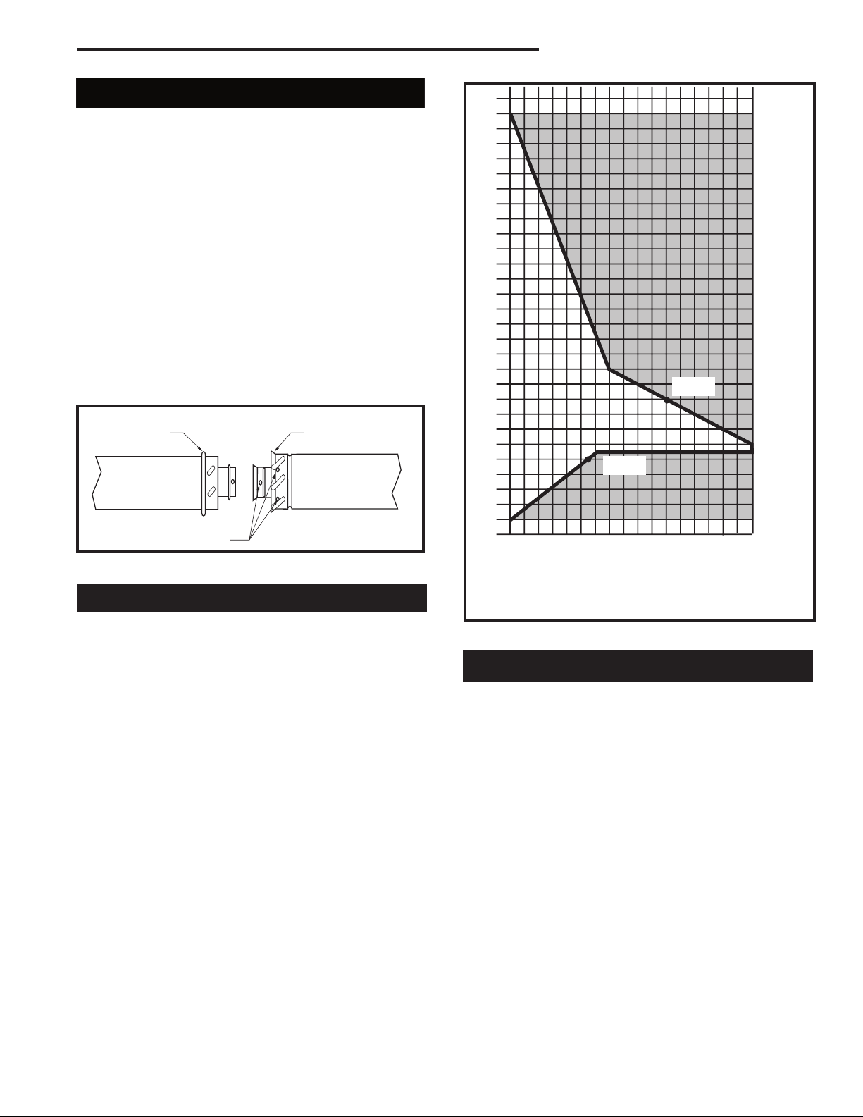
How to Use the Vent Graph
The vent chart should be read in conjunction with the
Female End
TWL100
Horizontal dimension from the outside face of the wall to
the center of the fireplace vent flange
Sidewall vent graph showing the relationship between vertical
and horizontal dimensions for a Direct Vent flue system.
Fig. 12 Sidewall venting graph. (Dimensions in feet)
following vent installation instructions to determine the
relationship of the vertical and horizontal dimensions of
the vent system.
1. Determine the height of the center of the horizontal
vent pipe exiting through the outer wall. Using this
dimension on the Sidewall Vent Graph (Fig. 12),
locate the point intersecting with the slanted graph
line.
2. From the point of this intersection, draw a vertical
line to the bottom of the graph.
3. Select the indicated dimension, and position the
fireplace in accordance with same.
Example A:
If the vertical dimension from the floor of the fireplace
is 11’ (3.4 m) the horizontal run to the face of the outer
wall must not exceed 14’ (4.3 m).
Example B:
If the vertical dimension from the floor of the unit is 7’
(2.14 m), the horizontal run to the face of the outer wall
must not exceed 8¹⁄₂’ (2.6 m).
20007628
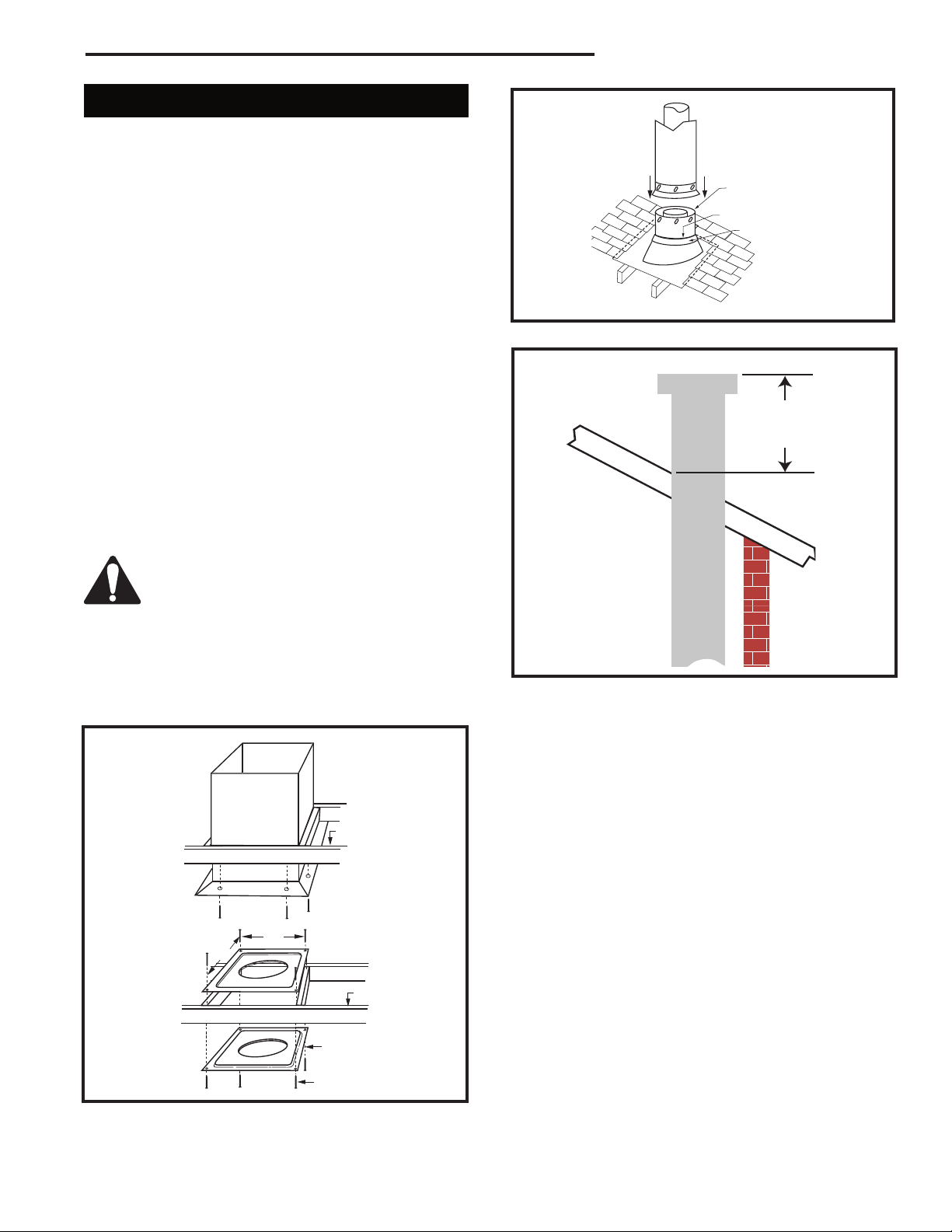
Rear Wall Vent Application
When installed as a rear vent unit this appliance may be
vented directly to a termination located on the rear wall
behind the appliance.
• Only CFM Corporation venting components are
approved to be used in these applications (See
‘Venting Components’ listed for different installation
requirements).
• The maximum horizontal distance between the rear
of the appliance (or end of the transition elbow in a
corner application) and the outside face of the rear
wall is 20” (508 mm). (Fig. 13, 14)
• Only one 45° elbow is allowed in these installations.
• Minimum clearances between vent pipe and com-
bustible materials are as follows:
Top - 2” (51 mm)
Sides - 1” (25 mm)
Bottom - 1” (25 mm)
13
RDVN Series Direct Vent Gas Fireplace
20 "
(5 0 8 m m )
Ma x .
20 "
(5 0 8 m m )
Ma x .
20” (508 mm)
Max.
Rear Vent Top View
10³⁄₈"
(265 mm)
Vent Opening for Combustible Wall
9³⁄₈"
(240 mm)
Framing
Detail
DVR584-600
Fig. 13 Rear vent application, no elbows.
45°
Rear Vent Top View, Corner Installation
Fig. 14 Rear vent application, one 45° elbow.
45°
FP836
Rear Wall Vent Installation
Twist Lock Pipe
Step 1
Locate and cut the vent opening in the wall. For combustible walls first frame in opening. (Fig. 15)
NOTE: When using flex vent, the opening will have to
be measured according to the 1/2” (13 mm) rise in 12”
(305 mm) vertical run.
Combustible Walls:
Cut a 10³⁄₈”H x 9³⁄₈” W (265 x 240
mm) hole through the exterior wall and frame as shown.
(Fig. 15)
Noncombustible Walls:
Hole opening should be 7¹⁄₂”
(191mm) diameter.
Zero clearance sleeve is only required for
combustible walls.
Step 2
Measure wall thickness and cut zero clearance sleeve
parts to proper length (Maximum 12” / 305 mm). Assemble sleeve to its maximum opening (10³⁄₈” x 9³₈”)
and attach to firestop assembly. (Fig. 16)
Step 3
Measure the horizontal length requirement for the venting including a 2” (51 mm) overlap, i.e. from the elbow
to the outside wall face plus 2” (51 mm). (Fig. 14)
Fireplace Hearth
Opening for Noncombustible Wall
7¹⁄₂" Dia.
(190 mm)
Fireplace Hearth
Fig. 15 Locate vent opening on wall.
Adjustable Zero Clear-
ance Sleeve
#8 Screws (2)
Adjustable Zero Clearance Sleeve
Fig. 16 Adjustable zero clearance sleeve.
Rnd.
Firestop
VO584-100
Max. Length 12”
(305mm)
#8 Screws (2)
#8 Screws
(2)
ZCS101
Step 4
Install the 4” (102 mm) vent to the appliance collar and
secure with 3 sheet metal screws. Install the 7” (178
mm) vent pipe to the appliance collar and secure with 3
sheet metal screws. It is not necessary to seal this connection. If a 45° elbow is being used attach the elbow
to the appliance in the same manner then attach the
venting to the elbow.
It is critical that there is no downward
slope away from the appliance when connecting the vent or elbow.
Step 5
Guide the venting through the vent hole as you place
the appliance in its installed position. Guide the 4” (102
mm) and 7” (178 mm) collar of the vent termination into
the outer ends of the venting. Do not force the termination. If the vent pipes do not align with the termination,
remove and realign the venting at the appliance flue
collars. (Fig. 17) Attach the termination to the wall as
outlined in the instruction sheet supplied with the termination.
14
20007628
Finished
1" (25mm)
24" (610mm)
Wall
Vent
Termination
RDVN Series Direct Vent Gas Fireplace
(Minimum 1” (25mm) rise)
FP1472
Fig. 19 There must be a 1” rise in 24” length.
Vertical Sidewall Applications
FP1005
Fig. 17 Side view of final unit location.
Rear Wall Vent Installation -
Flex Vent Pipe
Follow Steps 1 and 2 on Page 13.
Step 3
Install the 4” (102 mm) flex vent pipe to the appliance
collars described in “General Information Assembling
Vent Pipes”, Page 12. If the installation requires a 45°
angle, grasp the vent pipe close to the appliance collar
and bend to 45°. DO NOT exceed 45°. (Fig. 18)
Install the 7” vent pipe in the same manner as Step 2.
Termination
Flex Section
Appliance Collars
Since it is very important that the venting system maintain its balance between
the combustion air intake and the flue
gas exhaust, certain limitations as to vent
configurations apply and must be strictly
adhered to.
The Vent Graph shows the relationship between vertical and horizontal side wall venting and will help to
determine the various dimensions allowable.
Minimum clearance between vent pipes
and combustible materials is 1”(25 mm)
on top, bottom and sides unless otherwise
noted.
When vent termination exits through foundations less
than 20” (508 mm ) below siding outcrop, the vent pipe
must flush up with the siding. It is always best to locate
the fireplace in such a way that minimizes the number
of offsets and horizontal vent length.
The horizontal vent run refers to the total length of vent
pipe from the flue collar of the fireplace to the face of
the outer wall.
Horizontal plane means no vertical rise exists on this
portion of the vent assembly.
FP1473
Fig. 18 Grasp the vent pipe close to the collar and bend to
45° angle. Do not exceed 45°.
NOTE: There must be a 1” (25 mm) rise in a 24” (610
mm) length of flex vent.
Step 4
Assemble the flex vent to the collars on the termination
as you did on the appliance.
20007628
• The maximum horizontal vent run is 20 ft. (6.1 m)
when the vertical vent rise is 7¹⁄₂ ft. (2.3 m). (Fig. 20)
• The maximum number of 90° elbows per side wall
installation is three (3).
• If a 90° elbow is used in the horizontal vent run
(level height maintained) the maximum horizontal
vent length is reduced by 36” (914 mm). (Fig. 21)
This does not apply if the 90° elbows are used to
increase or redirect a vertical rise. (Fig. 22)
Example: According to the chart the maximum horizontal vent length in a system with a 7.5’ (2.3 m) vertical rise is 20’ (6 m) and if a 90° elbow is required in
the horizontal vent it must be reduced to 17’ (5.2 m).
In Figure 21 Dimension A plus B must not be greater
than 17’ (5.2 m).
15

RDVN Series Direct Vent Gas Fireplace
Maximum
20 ft. (6.1m)
7.5'
(2.3m)
7TDVRT90
Elbow
15 ft.
(4572mm)
48"
(1.2m)
12"
(305mm)
Maximum
3' (914mm)
7TDVRT90
Elbow
10 ft.
(3048 mm)
7 ft. 6 in.
(2286 mm)
7 ft.
(2134 mm)
1
2
3
4
1 + 2 + 3 + 4 = 270
o
Fig. 20 Maximum number of 90° elbows is three (3).
CFM141
• The maximum number of 45° elbows permitted per
side wall installation is two (2). These elbows can be
installed in either the vertical or horizontal run.
• For each 45° elbow installed in the horizontal run,
the length of the horizontal run MUST be reduced by
18” (45 cm). This does not apply if the 45° elbows
are installed on the vertical part of the vent system.
• The maximum number of elbow degrees in a system
is 270°. (Fig. 23)
Example:
Elbow 1 = 90˚
Elbow 2 = 45˚
Elbow 3 = 45˚
Elbow 4 = 90˚
Total angular variation = 270˚
Fig. 21 Maximum horizontal vent run.
Fig. 22 Maximum vent run with elbows.
A + B = 17’ (Max.)
CFM142
CFM147
CFM132
Fig. 23 Maximum number of elbow degrees.
• IMPORTANT •
Minimum clearance between vent pipes and combustible materials is one (1”) inch (25 mm) on bottom, sides
and top.
Twist Lock Vent Starter Kit 7TDVSK, plus Transition
Elbow 7TDVRT90 must be used in Vertical Sidewall
installations. The 4” pipe must be centered inside
the 7” pipe coming off the transition elbow.
Canadian & USA Installations:
The venting system must conform with local codes, or
in the absence of local codes, with National Fuel Gas
Code, ANSI Z223.1/NFPA 54 - latest edition, or CSA
B149.1 Installation Code.
Only CFM Corporation venting components specifically
approved and labelled for this fireplace may be used.
16
20007628

RDVN Series Direct Vent Gas Fireplace
X
7TDVRT90
X
Vertical Sidewall Installation
STEP 1
Locate vent opening on the wall. It may be necessary
to first position the fireplace and measure to obtain hole
location. Depending on whether the wall is combustible
or noncombustible, cut opening to size. (Fig. 24) For
combustible walls first frame in opening.
NOTE: When using flex vent, the opening will have to
be measured according to the 1” (25 mm) rise in 24”
(610mm) vent run.
Combustible Walls:
x 240 mm) hole through the exterior wall and frame as
shown.
Noncombustible Walls:
be 7¹⁄₂” (190 mm) in diameter.
Vent Opening for Combustible Wall
9³⁄₈”
(240mm)
(Fig. 24) Cut a 9³⁄₈”H x 9³⁄₈”W (240
(Fig. 24) Hole opening must
9³⁄₈”
(240mm)
Framing
Detail
Adjustable
Zero Clearance
Sleeve
#8 Screws
(2)
Firestop
Adjustable Zero Clearance Sleeve
Fig. 25 Adjustable zero clearance sleeve.
Ensure Pipes
are Concentric
Max. Length
12” (305mm)
#8 Screws (2)
#8 Screws
(2)
ZCS101
Fireplace Hearth
Opening for Noncombustible Wall
7¹⁄₂”
(190mm)
VO584-100
Fig. 24 Locate vent opening on wall.
STEP 2
Measure wall thickness and cut zero clearance sleeve
parts to proper length (MAXIMUM 12”/305 mm). Assemble sleeve and attach to firestop with #8 sheet
metal screws (supplied). Install firestop assembly. (Fig.
25)
Zero clearance sleeve is only required for
combustible walls.
STEP 3
Apply a bead of high temperature sealant to the inner
and outer flue collars of the fireplace and using appropriate venting component(s), attach to fireplace with
three (3) screws. (Fig. 26) Follow with the installation
of the inner and outer elbow. Again secure joints with
three (3) sheet metal screws. Wipe off any excess high
temperature sealant.
Bead of Sealant
(If necessary)
CFM143
Fig. 26 Apply sealant to inner and outer pipe.
STEP 4
Measure the horizontal length requirement including a
2” (51mm) overlap, i.e. from the elbow to the outside
wall finish plus 2”, or the distance required if installing a
second 90° elbow. (Fig. 27)
Always install
horizontal venting on a level
plane.
CFM136
Fig. 27 Measure horizontal length including 2” overlap.
20007628
17

RDVN Series Direct Vent Gas Fireplace
X
X
X
8"
(203mm)
8"
(203mm)
8"
(203mm)
8"
(203mm)
STEP 5
Use appropriate length of pipe section - telescopic or
fixed - and install the horizontal vent sections. The 20”
(508 mm) section of pipe which goes through the wall is
packaged with the 7TDVSK starter kit, and can be cut
to suit if necessary. (Fig. 28)
Sealing vent pipe and firestop gaps with
high temperature sealant will restrict cold
air being drawn in around fireplace.
High Temperature
Sealant
Vertical Sidewall Installation
Flex Vent Pipe
Follow Step 1 and 2 on Page 17.
Step 3
Install the four (4) spacer springs on the 4” flex vent
pipe. When installing the spacer springs around the 4”
pipe, stretch the spring to approximately 15” (381 mm),
wrap the spring around the pipe and interlock the ends
of the spacer spring approximately 2” (51 mm). (Fig.
30) Measure 8” (203 mm) from the end of the pipe.
Place the next spring 8” (203 mm) from the previously
installed spring. Place the next spring approximately
8” (203 mm) from the last spring. Finally place the last
spring approximately 8” (203 mm) from the last spring
installed. (Fig. 31) Maintain equal spacing between
spacer springs.
Spacer
Springs
CFM137
Fig. 28 Apply high temperature sealant.
STEP 6
Apply high temperature sealant to 4” (102 mm) and 7”
(178 mm) collars or the termination one inch away form
the end. Guide the vent termination’s 4” and 7” collars
into their respective vent pipes. Double check that the
vent pipes overlap the collars by 2” ( 51 mm). Secure
the termination to the wall with screws provided and
caulk around the wall plate to weatherproof. (Fig. 29)
T185a
Fig. 30 Wrap spacer spring around flex flue pipe, overlapping
ends.
Spacer Spring
Fig. 31 Install spacer springs.
Flex Outer Vent
Flue Pipe
4” Flex Vent
Pipe
FP1474a
Fig. 29 Horizontal length requirement.
18
CFM138
20007628

RDVN Series Direct Vent Gas Fireplace
24" (610mm)
Minimum*
Step 4
Install the 4” (102 mm) flex vent pipe to the termination
cap collar as described on Page 12.
Step 5
Slide the 7” (178 mm) flex vent pipe over the 4” flex
vent pipe and secure the 7” collar as described on Page
12.
Step 6
Be sure to follow the 1” (25 mm) rise in a 24” (610 mm)
horizontal run rule. Trim off excess vent material, then
install the 4” flex to the flue collar and the 7” flex to the
appliance collar. Secure venting with band clamps provided. Refer to Page 12, Figure 10.
Below Grade Installations
When it is not possible to meet the required vent terminal clearances of 12” (305 mm) above grade level a
snorkel vent kit is recommended. It allows installation
depth of down to 7” (178 mm) below grade level. The
7” is measured from the center of the horizontal vent
pipe as it penetrates through the wall.
If venting system is installed below
ground, we recommend a window well with
adequate and proper drainage.
Ensure sidewall venting clearances are observed.
If installing a snorkel a minimum 24” (610 mm) vertical
rise is necessary. The maximum horizontal run with
the 24” (610 mm) vertical pipe is 36” (914 mm). This
measurement is taken from the collar of the fireplace
(or transition elbow) to the face of the exterior wall.
Refer to the Sidewall Vent Graph for extended
horizontal run if the vertical rise exceeds 24” (610 mm).
1. Establish vent hole through the wall. (Page 17, Fig.
24)
2. Remove soil to a depth of approximately 16”
(406mm) below base of snorkel. Install drain pipe.
Install window well (not supplied). Refill hole with 12”
(305mm) of coarse gravel leaving a clearance of approximately 4” (102 mm) below snorkel. (Fig. 32)
3. Install vent system.
4. Ensure a watertight seal is made around the vent
pipe coming through the wall.
5. Apply high temperature sealant caulking (supplied)
around the 4” and 7 “ snorkel collars.
6. Slide the snorkel into the vent pipes and secure to
the wall.
7. Level the soil to maintain a 4” (102 mm) clearance
below snorkel. (Fig. 32)
Zero Clearance Sleeve
(if required)
Firestop
7” Pipe
BG400
Fig. 32 Below grade installation.
Do not back fill around snorkel. A clearance of at least 4” (102 mm) must be maintained between snorkel and the soil.
If the foundation is
recessed, use recess
brackets (not supplied)
for securing lower
portion of the snorkel.
Fasten brackets to
wall first, then secure
to snorkel with self
drilling #8 x 1/2 sheet
metal screws. It will be
necessary to extend
vent pipes out as far
as protruding wall
face. (Fig. 33)
Foundation
Recess
Recess
Brackets
Watertight Seal
Around
Pipe
Fig. 33 Snorkel installation, recessed foundation.
7TDVSNORK
(Snorkel)
4” (102mm)
Clearance
Min.
Window
Well
Gravel
Drain
Foundation Wall
*A minimum of 24” (610mm) ver
tical pipe must be installed when
using the 7TDVSNORK Kit.
Snorkel
Wall Screws
Sheet Metal
Screws
BG401
-
20007628
19

RDVN Series Direct Vent Gas Fireplace
H
12
x
Vertical Through-the-Roof Applications
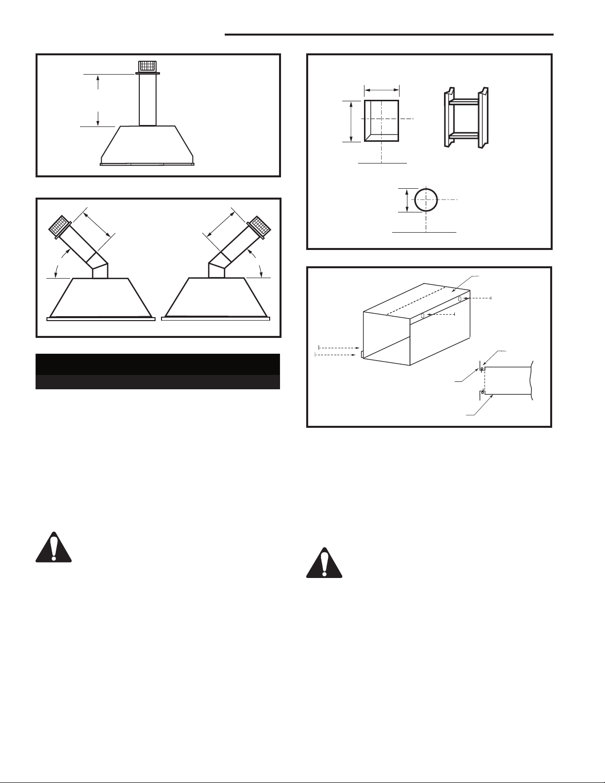
This Gas Fireplace has been approved for:
• Vertical installations up to 40’ (12 m) in height. Up
to a 10’ (3 m) horizontal vent run can be installed
within the vent system using a maximum of two 90°
elbows. (Fig. 34)
Maximum
10’
(3m)
Minimum
8’ (2.4m) /
Maximum
40’ (12m) Vertical
Rise
Pipe Straps Every
3’ (914mm)
Max.
8
(2.4m)
45°
Max.
8’
(2.4m)
45°
Typical Offset Installation
Fig. 35 Typical offset application.
Vent Cap
40’
(12m)
Lowest Discharge
Opening
Typical
Ceiling
Support
Application
Typical Roof
Support Ap
plication
-
FP1021
CFM148
Fig. 34 Support straps for horizontal runs.
• Up to two 45° elbows may be used within the
horizontal run. For each 45° elbow used on the
horizontal level the maximum horizontal length must
be reduced by 18” (457 mm).
Example: Maximum horizontal length
0 x 45° elbows = 10’ (3 m)
1 x 45° elbows = 8¹⁄₂’ (2.6 m)
2 x 45° elbows = 7’ (2.1 m)
• A minimum of an 8’ (2.4 m) vertical rise.
• Two sets of 45° elbows offsets within these vertical
installations. From 0 to a maximum of 8’ (2.4 m) of
vent pipe can be used between elbows. (Fig. 35)
• 7DVCS must be used to support offsets. (Fig. 35)
This application will require that you first determine
the roof pitch and use the appropriate starter kit.
(Refer to Venting Components List)
• The minimum height of the vent above the highest
point of penetration through the roof is 2’ (610 mm).
(Fig. 36)
Gas Vent
Roof Pitch
is X/12
H (Min.) - Minimum height
from roof to lowest discharge opening
T183
Roof Pitch H (Min.)
Flat to 6/12 12” (305 mm)
6/12 to 7/12 15” (381 mm)
Over 7/12 to 8/12 18” (457 mm)
Over 8/12 to 16/12 24” (610 mm)
Over 16/12 to 21/12 36” (914 mm)
Fig. 36 Vertical termination location.
20
20007628
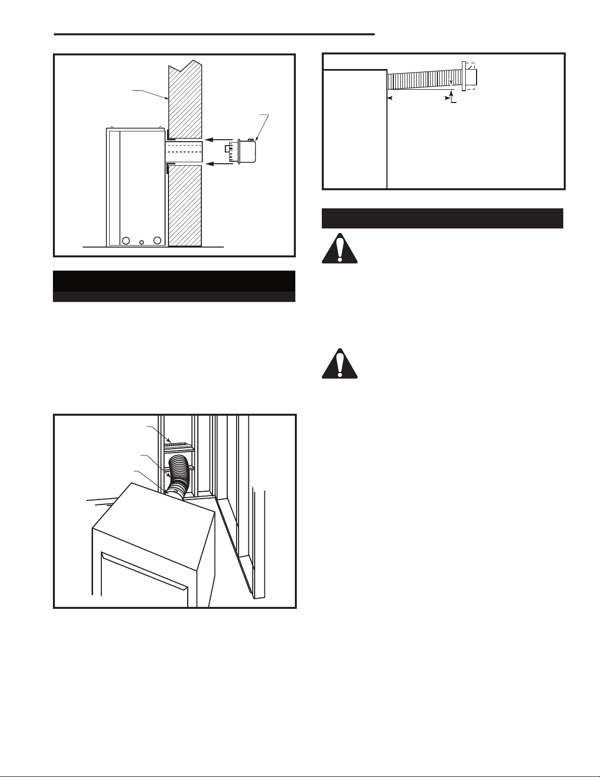
Vertical Through-the-Roof Installation
11"
(279mm)
11"
(279mm)
1. Locate your fireplace.
2. Plumb to center of the (4” (102 mm) flue collar from
ceiling above and mark position.
3. Cut opening equal to 9
4. Proceed to plumb for additional openings through
the roof. In all cases, the opening must provide a
minimum of 1” (25 mm) clearance to the vent pipe,
i.e., the hole must be at least 9³⁄₈” x 9³⁄₈” (240 x 240
mm).
5. Place fireplace into position.
6. Place firestop(s) #7DVFS or Attic Insulation Shield
#7DVAIS into position and secure. (Fig. 37)
7. Install roof support (Fig. 35) and roof flashing making
sure upper flange of flashing is below the shingles.
(Fig. 38)
8. Install appropriate pipe sections until the venting is
above the flashing. (Fig. 38)
9. Install storm collar and seal around the pipe.
10. Add additional vent lengths for proper height. (Fig.
39)
11. Apply high temperature sealant to 4” and 7” collars.
³⁄₈” x 9³⁄₈” (240 x 240 mm).
RDVN Series Direct Vent Gas Fireplace
#8 Sheet Metal Screws
(3 per joint)
Sealant
Storm Collar
TWL101a
Fig. 38 Roof flashing.
Min. 2’ (610 mm)
If there is a room above ceiling level,
firestop spacer must be installed on both
the bottom and the top side of the ceiling
joists. If an attic is above ceiling level a
7DVAIS (Attic Insulation Shield) must be
installed.
The enlarged ends of the vent section always face
downward. (Fig. 38)
Attic Insulation
Shield
Joist
Ceiling Installation
Upper Floor
Joist
CFM190
Fig. 39 Minimum termination to roof clearance.
Firestop Spacer
Fig. 37 Place firestop spacer(s) and secure.
Nails (4)
20007628
CFM100a
21

RDVN Series Direct Vent Gas Fireplace
Twist Lock Venting Components
7TDVSK - Through the wall Rear Vent Termination
Starter Kit Model 7TDVSK - Sidewall Venting (Twist Lock Pipe)
Model 7FDVSK - Sidewall Venting (Flex Vent Pipe)
Starter Kit - Model 7TDVSKV - Vertical Venting
for 7TDVSKV-A order 1/12 to 6/12 roof pitch
for 7TDVSKV-B order 7/12 to 12/12 roof pitch
for 7TDVSKV-F order flat roof
Starter Kit for Below Grade Installation
Model 7TDVSKS -Snorkel Kit (Twist Lock Pipe)
Model 7FDVSKS -Snorkel Kit (Flex Vent Pipe)
45o Elbow
7TDV45 for Rear Vent to Vertical Vent
or Vertical/Horizontal Offsets
90o Transition Elbow
7TDVRT90 for Rear Vent to Vertical Vent
90° Elbow
7TDV90 Vertical/Horizontal Offset
Telescopic vent sections
7TDVP1117 -11” to 17” adjustable length
7TDVP3567 -35” to 67” adjustable length
Pipe sections for vertical or horizontal venting
Model 7TDVP8” - 4 per box
Model 7TDVP12” - 4 per box
Model 7TDVP24” - 4 per box
Model 7TDVP36”
Model 7TDVP48”
Firestop Spacer
Model 7DVFS
Attic Insulation Shield
Model 7DVAIS
22
Vertical/Horizontal Combination Offset Support
Model 7DVCS
20007628
Operating Instructions
1.
2.
�
Glass Information
Only glass approved by CFM Corporation
should be used on this fireplace.
• The use of any non-approved replacement glass will
void all product warranties.
• Care must be taken to avoid breakage of the glass.
• Do not operate appliance with glass front
removed, cracked or broken.
• Replacement glass (complete with gasket) is
available through your CFM Corporation dealer
and should only be installed by a licensed
qualified service person.
RDVN Series Direct Vent Gas Fireplace
Lower Clamps
Window
Frame
Assembly
Push
Clamp
Handle
Fig. 41 Window frame assembly removal.
Window
Frame Assembly
Pull
Clamp
Hook
FP1228
Louvre Removal
The top louvre
panel is removed
by lifting the
panel vertically
and pulling it
away from the
appliance. (Fig.
40)
The lower access
door is hinged
along the bottom
edge and is
folded down to
allow access.
FP1227
Fig. 40 Remove top louvre assembly.
Glass Panel
Window Frame Removal
1. Turn the fireplace OFF (including the pilot)
2. If the unit has been operating allow time for the
components to cool.
3. Remove the top louvre assembly.
4. Open the lower louvre panel.
5. Release the two clamps securing the lower edge of
the frame by pulling down on the handles. (Fig. 41)
6. Tilt the glass frame out slightly at the bottom, lift the
7. To replace the glass frame reverse the procedure.
20007628
frame up and away from the fireplace.
Louvre
Glass Cleaning
It is necessary to periodically clean the glass. During
start-up condensation, which is normal, forms on the
inside of the glass. This condensation causes lint, dust
and other airborne particles to cling to the glass surface.
Also initial paint curing may deposit a slight film on
the glass. It is therefore recommended that the glass
be cleaned two or three times with a non-ammonia
based household cleaner and warm water (We
recommend gas fireplace glass cleaner) within the
first few weeks of operation.
After the initial cleaning process the glass should be
cleaned two or three times during each operating
season depending on the environment in the house.
Clean the glass after the first two weeks of
operation.
Do not clean glass when hot.
Do not use abrasive cleaners.
Do not strike or slam glass.
23

RDVN Series Direct Vent Gas Fireplace
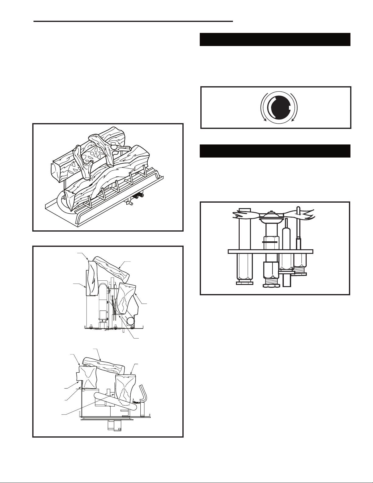
Installation of Logs, Lava Rock & Ember Material
Unpack the logs from packaging and remove each log
from its wrapping materials.
The logs are fragile and should be handled
with care. Keep the packaging material out
of the reach of children and dispose of the
material in a safe manner.
The embers supplied with your fireplace
are made from platinum coated embers
and should be handled carefully. Wash
your hands immediately after touching
to avoid irritation. The embers must be
placed correctly in order to function
properly.
Log Installation - 33RDVN
1. Open glass door (if installed).
2. Remove logs from the packaging. (As with all plastic,
these bags are not toys and should always be kept
away from children and infants.)
3. Place rear log on back bracket. Ensure that log is
firmly positioned and there is no side-to-side movement.
4. Place the front log on the front burner (starting toward the rear of the front burner) and slide it forward
until the notches lock into place.
5. Place the top logs onto the locator notches. Ensure
that the logs are secure. (Fig. 42)
Log Installation - 36/39RDVN
Attention: Glass door should be removed when install-
ing logset and prior to lighting the unit.
1. Remove glass door (Refer to “Window Frame Removal”).
2. Remove logs from carton and inspect. Refer to Fig
ure 43.
3. Rear log should be installed onto rear log supports.
Match up slots on rear of log with the vertical log
bracket tabs. Push log back as far as it will go.
4. The front log should be placed on the front log sup
ports, slots aligned with tabs and log bottom in channel.
5. Top twigs can then be placed in their designated po
sitions provided with pins on back logs and grooves
on the front log. Front log must be upright.
-
-
-
Fig. 42 33RDVN log placement.
24
TL126
TL119
Fig. 43 Correct log placement for 36/39RDVN.
All Models
6. Place platinum embers loosely along top surface
of burner along entire length of ported area of front
burner. DO NOT place embers on back portion of
burner. Use individual pieces of embers no larger
than dime size, about 1/16” thick (fluffed up thickness). Use a single layer of embers and DO NOT
overlap pieces. Ember material should be fluffed up
and not compressed. When properly placed, all embers will glow red. Adding more embers than necessary will detract from appearance.
20007628
RDVN Series Direct Vent Gas Fireplace
L
O
H
I
Turn
counterclockwise
to increase
flame height
Turn clockwise
to decrease
flame height
7. Ember tray ends beyond burner port area and area
in front of grate may be covered with lava rock to
suit individual appearance preferences.
8. Purge lines and test pilot operation.
9. Replace glass door. The door must be installed
before operating the fireplace.
10. Flame should not impinge (touch) on logs.
WARNING: Do not place lava rock or any other materials on the burner. Use only certified material supplied
with this fireplace. Using uncertified materials will void
the warranty.
Flame & Temperature Adjustment
For units equipped with ‘HI/LO’ valves the flame
adjustment is accomplished by rotating the ‘HI/LO’
adjustments knob located near the center of the gas
control valve. (Fig. 46)
Fig. 46 Flame adjustment knob for SIT valve.
Flame Characteristics
It is important to periodically perform a visual check of
the pilot and burner flames. Compare them to Figure
47.
If the flame patterns appear abnormal contact a
qualified service provider for service and adjustment.
Fig. 44 Logs in final position (36RDV shown).
Back Log
Twig
33RDV
Bracket
36/39RDV
Twig
Back Log
Slot
Bracket
TL121
FP1229
Fig. 47 Correct pilot flame appearance.
Front Log
Bracket
Front Log
Bracket
Fig. 45 Side view of logset.
20007628
TL122
25

RDVN Series Direct Vent Gas Fireplace
PILOT
ON
OFF
ON
P
I
L
O
T
O
F
F
O
F
F
5
4
3
2
1
O
F
F
P
i
l
o
t
3/8" - 1/2"
Lighting and Operating Instructions
FOR YOUR SAFETY READ BEFORE LIGHTING
WARNING:If you do not follow these instructions exactly, a fire or explosion
may result causing property damage, personal injury or loss of life.
A. This heater has a pilot which must be lit manu
ally. When lighting the pilot follow these instructions exactly.
B. BEFORE LIGHTING smell all around the
heater area for gas. Be sure to smell next to
the floor because some gas is heavier than air
and will settle on the floor.
WHAT TO DO IF YOU SMELL GAS
• Do not try to light any fireplace
• Do not touch any electric switch
• Do not use any phone in your building
• Immediately call your gas supplier from a
neighbor’s phone.
Lighting Instructions
-
Follow the gas supplier’s instructions.
• If you cannot reach your gas supplier, call
the Fire Department
C. Use only your hand to push in or turn the gas
control knob. Never use tools. If the knob will not
push in or turn by hand, do not try to repair it, call a
qualified service technician. Applying force or any
attempted repair may result in a fire or explosion.
D. Do not use this fireplace if any part has been under
water. Immediately call a qualified service technician to inspect the heater and to replace any part of
the control system and any gas control which has
been under water.
1. STOP! Read the safety information above.
2. Turn off all electrical power to the fireplace.
3. For MN/MP/TN/TP appliances ONLY, go on to
Step 4. For RN/RP appliances turn the ON/OFF
switch to “OFF” position or set thermostat to
lowest level.
4. Open control access panel.
5. Push in gas control knob slightly and turn clockwise to “OFF”.
Euro SIT SIT NOVA
Honeywell
6. Wait five (5) minutes to clear out any gas. Then
smell for gas, including near the floor. If you
smell gas, STOP! Follow “B” in the safety information above. If you do not smell gas, go to the
next step.
7. Remove glass door before lighting pilot. (See
Glass Frame Removal section).
8. Visibly locate pilot by the main burner.
9. Turn knob on gas control counterclockwise
to “PILOT”.
10. Push the control knob all the way in and hold.
Immediately light the pilot by repeatedly depressing the piezo spark ignitor until a flame appears.
Continue to hold the control knob in for about one
(1) minute after the pilot is lit. Release knob and it
will pop back up. Pilot should remain lit. If it goes
out, repeat steps 5 through 8.
• If knob does not pop up when released, stop
and immediately call your service technician or
gas supplier.
• If after several tries, the pilot will not stay lit,
turn the gas control knob to “OFF” and call your
service technician or gas supplier.
11. Replace glass door.
12. Turn gas control knob to “ON” position.
13. For RN/RP appliances turn the ON/OFF switch to
“ON” position or set thermostat to desired setting.
14. Turn on all electrical power to the fireplace.
1. Turn the ON/OFF switch to Off position or set
the thermostat to lowest setting.
2. Turn off all electric power to the fireplace if
service is to be performed.
26
To Turn Off Gas To Heater
3. Open control access panel.
4. Push in gas control knob slightly and turn clockwise to “OFF”. Do not force.
5. Close control access panel.
20007628

RDVN Series Direct Vent Gas Fireplace
Troubleshooting
SIT Millivolt Valve
NOTE: Before troubleshooting the gas control system, be sure external shut off is in the “ON” position.
WARNING: Before doing any gas control service work, remove glass front!
Table 1
Valve Type Main Operator Safety Magnet
NOVA MV Plus Minimum Voltage 145mV Hold-in Current Less than 285mA
Coil Resistance 2.25Ω ± 0.5Ω Drop-out Current Greater than 125mA
Coil Resistance 0.108Ω ± 0.003Ω
System Checks
Problem Possible Cause Solution
Pilot will not light. Air in gas lines. Bleed all air from gas lines.
Wrong inlet pressure. With the main burner functioning, adjust the inlet pressure
regulator to supply gas to the appliance within the design
parameters of the appliance manufacturer. (Typically 7”NG,
11”LPG).
Defective spark electrode. Replace piezo wire if insulation is cracked or the tip is cor-
roded.
Verify that the spark gap between the pilot and the electrode
is correct.
Defective piezo wire. Replace piezo wire if insulation is damaged, or the wire is bro ken or corroded.
Safety interlock function engaged. Allow thermocouple to cool until the mv drops below the hold in requirements of the safety magnet, (30 seconds or less).
Re-light pilot.
Pilot will not hold. Wrong inlet pressure. With the main burner functioning, adjust the inlet pressure
regulator to supply gas to the appliance within design
parameters of the appliance manufacturer. (Typically 7”NG,
11”LPG)
Pilot adjustment screw not After the pilot has been lit for approximately three minutes,
properly adjusted. and only the thermo-generator wire connected to the main
operator head, measure the voltage across TPTH and TP.
This open circuit voltage should be between 500mv and
750mv. Tune the pilot adjustment screw until the mv reading
falls within these parameters. (Counter-clockwise increases
mv reading, clockwise decreases).
Thermocouple or Make certain that the thermocouple and thermo-generator are
thermo-generator not properly fully inserted and tightened into their receptacles in the pilot
inserted into the pilot housing. head. The thermocouple should be threaded into the valve
hand-tight, plus 1/4 turn with a wrench.
Thermocouple or With the thermocouple and thermo-generator tips cool, clean
thermo-generator has film the upper 3/8” with a very fine emery cloth.
build-up on tip.
Electrical resistance too high. Using a very fine emery cloth, clean thermo-generator and
thermocouple connections at valve. Tighten thermocouple into
valve hand-tight, plus 1/4 turn with a wrench.
Defective thermocouple. Verify that thermocouple is not kinked or damaged. Check
(mv Plus systems) open circuit voltage of thermocouple. Voltage should be
between 18mv and 28mv. If voltage is less than 14mv,
replace thermocouple.
20007628
27
RDVN Series Direct Vent Gas Fireplace
System Checks (continued)
Problem Possible Cause Solution
Defective thermo-generator. After the pilot has been lit for approximately three minutes,
(Millivolt system) and only the thermo-generator wire connected to the main
operator head, measure the voltage across TPTH and TP.
This open circuit voltage should be between 500mv and
750mv. Tune the pilot adjustment screw until the mv reading
falls within these parameters. (Counter-clockwise increases
mv reading, clockwise decreases)
Defective safety magnet. Verify operation of safety magnet in the following
(mv Plus systems) manner.
(A) Depress and hold pilot button.
(B) Verify open-circuit thermocouple voltage as de-
scribed in previous step.
(C) Reconnect thermocouple to valve.
(D) Measure the Millivoltage between the solder button
on the base of the safety magnet, and the valve
body. If the mv reading is above 6mv for vented
appliances, or 8.5 mv for un-vented appliances, and
the safety magnet does not hold, replace the valve.
(E) If closed circuit mv reading is the same as the open
circuit reading, the coil is electrically open. Replace
the valve.
Defective Safety Magnet Verify operation of safety magnet in the following
(Millivolt system) manner.
(A) Remove all wires from the terminals of the main
operator.
(B) Measure the electrical voltage between the termi nals TPTH and TP. If the voltage is above 110mv
and the safety magnet does not hold, replace the
valve.
Pilot orifice blocked. Replace orifice with a new orifice of the exact size and
type.
Pilot drops out. Wrong pilot orifice. Replace the orifice with a new orifice supplied specifi cally for the appliance and gas type in question.
No gas to main burner Low gas pressure to appliance. With the main burner functioning, adjust the inlet pres sure regulator to supply gas to the appliance within the
design parameters of the appliance manufacturer.
(Typically 7”NG, 11”LPG).
Pilot not lit. Light pilot and wait for thermo-generator to heat up
sufficiently to power the main operator. If pilot fails to
light, or hold, refer to above sections.
Control knob not in ON Rotate OFF/PILOT/ON control knob to the ON position.
position.
Thermostat/wall switch Thermostat not in ON position. Turn thermostat ON, and adjust temperature control to
will not cycle main call for heat.
burner.
28
20007628

RDVN Series Direct Vent Gas Fireplace
System Checks (continued)
Problem Possible Cause Solution
Thermo-generator output After the pilot has been lit for approximately three
voltage not within design minutes, and only the thermo-generator wire connected
parameters. to the main operator head, measure the voltage across
TPTH and TP. This open circuit voltage should be
between 500mv and 750mv. Tune the pilot adjustment
screw until the mv reading falls within these parameters.
(Counter-clockwise increases mv reading, clockwise
decreases) If unable to meet minimum requirements,
replace thermo-generator.
Defective thermostat or (A) With the pilot adjusted properly, ( After the pilot has
thermostat wiring. been lit for approximately three minutes, and only
the thermo-generator wire connected to the main
operator head, measure the voltage across TPTH
and TP. This open circuit voltage should be be
tween 500mv and 750mv. Tune the pilot adjustment
screw until the mv reading falls within these param eters. Counterclockwise increases mv reading,
clockwise decreases), place a jumper wire between
TPTH and TH. Take a mv reading across the TPTH
and TP terminals on the valve. This closed circuit
voltage should not fall below 300mv. Record read
ing.
(B) Remove jumper wire from the TPTH and TH con nections, and reconnect the thermostat wires to the
same terminals. Take the closed circuit voltage as
described in the previous step. If the mv reading
drops below 150mvm, excessive resistance exists in
the thermostat circuit, and must be isolated and
eliminated.
Thermostat/wall switch Defective wall switch. Repeat the above troubleshooting items covered under
will not cycle main “Defective thermostat or thermostat wiring”, except
burner. substitute the words “wall switch” where the word
“thermostat” appears in the instructions.
Excessive wire resistance. Make certain that all mv connections are made using
wire of the proper size. (Reference Page 26).
Valve wired wrong. Thermo-generator leads must be connected to the
TPTH and TP connections of the main operator. Ther mostat wires must be connected to the TPTH , and TH
terminals of the valve.
Main burner lights in Main operator coil defective. Verify electrical resistance of main operator coil in the
the PILOT position. following manner.
(A) Remove all wires from operator head.
With an Ohm meter, measure electrical resistance
between TP and TH terminals. If the resistance does
not fall within specification, replace valve. (See table 1).
Debris on seat of main valve. Replace valve.
Main seat blown out as a Replace valve.
result of exposing LPG gas
valve to unregulated line
pressure in excess of 15 PSI.
20007628
29

RDVN Series Direct Vent Gas Fireplace
Attention: All fireplaces are shipped from the factory equipped for natural gas. Units must be converted for use with propane (LP) gas.
Fuel Conversion Instructions
WARNING: This HI/LO conversion kit must ONLY be
applied as part of a conversion kit supplied by the
appliance manufacturer for the specific appliance
and type of gas being converted.
The conversion shall be carried out in accordance
with the requirements of the provincial authorities having jurisdiction and in accordance with the
requirements of the CSA B149.2 Installation Code
(Canada) and with the requirements of the National
Fuel Gas Code Z223.1/NFPA 54 (United States).
WARNING: This conversion kit shall be installed
by a qualified service agency in accordance with
the manufacturer’s instructions and all applicable
codes and requirements of the authority having
jurisdiction. If the information in this instruction is
not followed exactly, a fire, explosion or production
of carbon monoxide may result causing property
damage, personal injury or loss of life. The qualified
service agency is responsible for the proper installation of this kit. The installation is not proper and
complete until the operation of the converted appliance is checked as specified in the manufacturer’s
instructions supplied with the kit.
Installer Notice: Using an ink pen, fill out the required information on the conversion label. Remove
the backing from label and stick label in a visible
position on bottom of fireplace close to gas valve.
Installer Notice: These instructions must be left
with the appliance.
Instructions for converting your fireplace from Natural
gas to Propane/LP gas.
All fireplaces are shipped from the factory equipped to
operate on Natural gas. To convert the fireplace to operate on Propane/LP gas, follow the instructions below.
Please see the appropriate parts list for your model for
parts included with the fireplace.
Check the items in the kit with the parts list. Notify the
supplier of any items that are missing before installing
the conversion kit.
1. Turn off gas supply.
2. Turn off the electrical supply to the appliance if so
equipped.
Replace Burner Orifice
33RDVN:
1. Bend retaining bracket away from burner tube. (Fig.
48)
2. With suitable tool, loosen the split nut assembly
from the air shutter. (Fig. 49) Lift burner tube up and
away.
Retaining Bracket
Burner Tube
Fig. 48 Bend retaining bracket away from tube.
Burner Tube
Air Shutter
Split Nut Assembly
Fig. 49 Loosen split nut assembly from air shutter and remove burner tube.
FC100
FC105
36/39RDVN:
1. Remove lava rock to expose screws and remove
grate assembly.
2. Use screwdriver and bend burner tabs outward. (Fig.
50)
3. Loosen the split nut assembly to remove from
burner/air shutter. Slide burner tube to the left and
off burner orifice. (Fig. 50)
Burner Tabs
Split Nut Assembly
Fig. 50 Bend tabs down, loosen split nut assembly and slide
burner tube to the left.
T257
All Models:
Remove the two (2) screws holding the pilot to the
burner bracket.
30
20007628

All Models:
1. Using a suitable tool replace natural orifice #47 with
propane orifice #56 for model 33RDVP, or replace
natural orifice #45 with propane orifice #55 for model
36RDVP, or replace natural orifice #42 with propane
orifice #54 for model 39RDVP furnished with conver
sion kit. Tighten orifice with suitable tool until gas
tight. (Fig. 51)
Split Nut Assembly
Air Shutter
RDVN Series Direct Vent Gas Fireplace
-
Pilot
Hood
Allen
Wrench
Burner Orifice
Fig. 51 Replace burner orifice with correct conversion orifice.
T259
2. Move burner tube back to original position, tighten
split nut assembly and bend tabs back up.
3. Set the air shutter opening for propane/LP gas.
Tighten air shutter screw. (Refer to Figure 52 and
Chart on Page 35)
3/8” - 33RDVP
3/8” - 36RDVP
3/8” - 39RDVP
T207
Fig. 52 Air shutter settings for propane/LP gas.
NOTE: Failure to adjust air shutter to the proper set-
ting will produce sooting.
4. Fasten pilot to burner bracket with two (2) screws.
5. Replace grate assembly.
WARNING: Failure to position the parts in accor
dance with these diagrams or failure to use only
parts specifically approved with this heater may
result in property damage or personal injury.
Replace Pilot Orifice
1. The pilot hood is held in place by spring pressure.
Remove the hood by pulling it directly up from the
pilot bracket. (Fig. 53)
2. Insert a 3/32” (4 mm) Allen wrench into the hex
agonal keyway of the injector (Fig. 53) and rotate it
counterclockwise until it is free of the injector journal.
(Fig. 53)
3. Verify that the new injector is proper for the applica
tion. The injector size is stamped on the side of the
injector near the top. LPG injectors have a groove
machined around their circumference near the top,
while the NG injectors do not have a groove. (Fig.
-
Conversion
Orifice
T207
Fig. 53 Remove pilot hood and orifice. Insert conversion
orifice.
LPG NG
T208
Fig. 54 Injectors.
54) Install the conversion orifice furnished with unit
(Conversion Kit).
4. Insert the Allen wrench into the end of the injector.
Insert the injector into injector journal, and rotate
the injector clockwise until a torque of 9 in/lbs. is
achieved. Replace the pilot hood by aligning the
tab on the base of the hood with the slot in the side
-
of the pilot journal. Push the hood down directly
onto the pilot bracket. (Fig. 53) The hood must sit
squarely on the bracket for proper operation. Check
to insure the hood is properly seated onto the pilot
bracket.
20007628
31
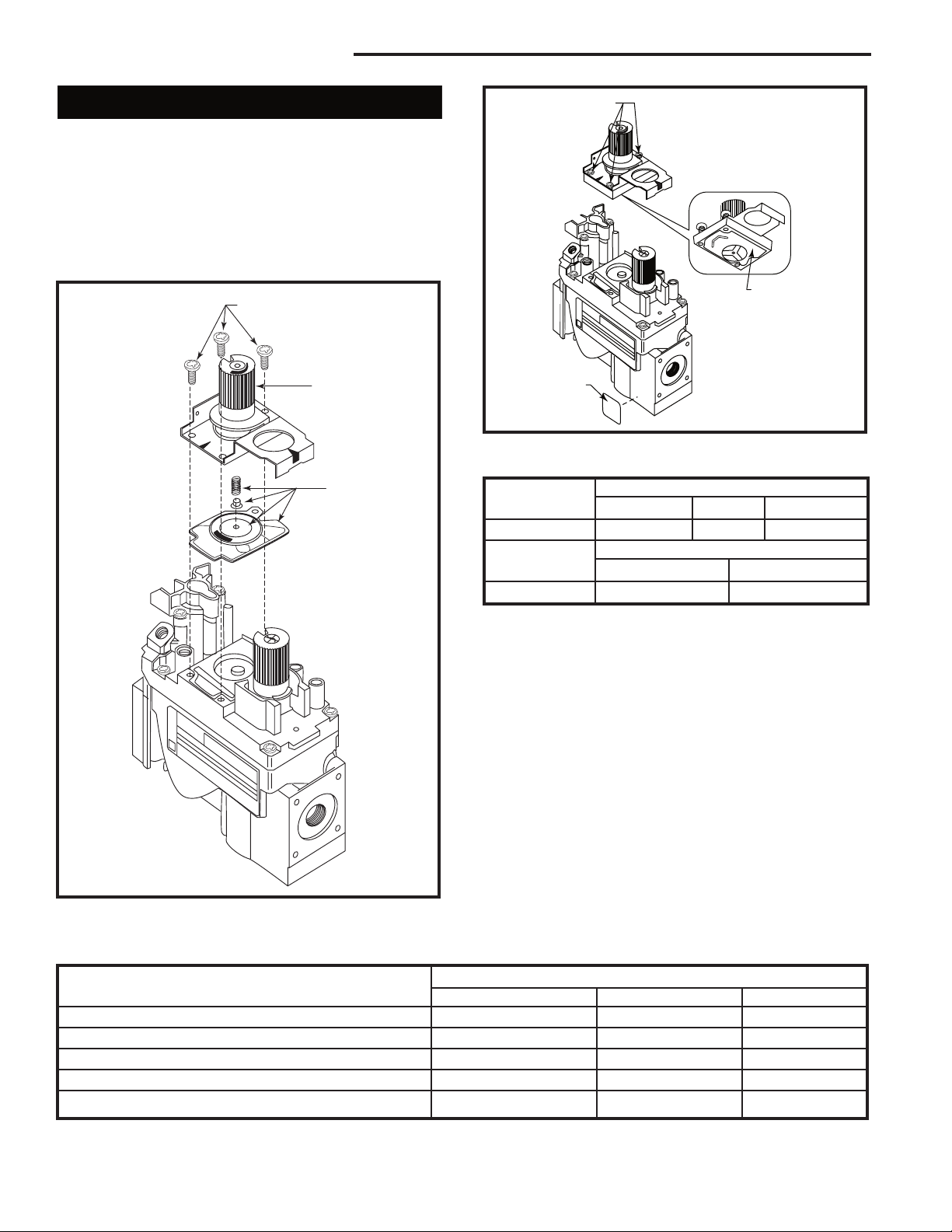
RDVN Series Direct Vent Gas Fireplace
A
B
C
O
F
F
P
I
L
O
T
O
N
D
E
F
O
F
F
P
I
L
O
T
O
N
Convert Valve to LP
1. Using a Torx T20 bit or slotted screwdriver, remove
and discard the three (3) pressure regulator mounting screws (A), pressure regulator tower (B) and
diaphragm (C). (Fig. 55)
2. Insure the rubber gasket (D) is properly positioned
and install the new HI/LO pressure regulator assembly to the valve using the new screws (E) supplied
with the kit. Tighten screws securely. (Fig. 56)
FC107
Fig. 55 Remove mounting screws, pressure regulator tower
and diaphragm assembly, and discard.
FC108
Fig. 56 Replace regulator.
Pressure ranges are:
Gas Supply Pressure (inches w.c.)
Minimum Normal Maximum
LP (Propane) 10.8 11.0 14.0
Manifold Pressure (inches w.c.)
Nornal (HI) Normal (Low)
LP (Propane) 10.0” 6.3”
3. Install the enclosed installation label (F) to the valve
body where it can be seen.
4. Apply gas to system and relight appliance according
to manufacturer’s instructions.
5. With the main burner “ON”, test the new pressure
regulator assembly for leaks using a soap solution.
6. Relight the main burner in both the HI and LO posi
tions, and verify proper burner ignition and operation.
7. Check inlet and manifold pressures. Loosen screw
in test port 1/2 turn to measure pressure. Tighten
screw when measurement is complete.
Manifold pressure can be measured by using a 5/16”
I.D. hose in the right hand side of the valve and connecting a manometer. Two test gauge ports are accessible for test gauge connection. Refer to Page 32.
Kit Number
Conversion Parts Included with Kit 33DVCKP 36DVCKP 39DVCKP
Main Burner Orifice - LP 76776 20007908 20007907
Label, Conversion 10002876 10002876 10002876
Pilot, Orifice - LP 76263 76263 76263
Conversion Pressure Regulator Assembly - LP 74655 74655 74655
Label, SIT Valve -- -- --
32
20007628

Unit Adjustment
RDVN Series Direct Vent Gas Fireplace
Once installed, the unit should be operated at least
three (3) times to ensure that all is in working order.
NOTE: Manufacturing oils will smoke during initial firing
of appliance. Open windows for ventilation.
Before leaving, the installer should make the following
checks:
Btu Input/Gas Pressure
The fireplace input is marked on the Rating Plate. The
gas inlet pressure specified in Table 1 is the pressure
where the field-installed gas line connects to the gas
control. This is measured at the inlet test port on the
gas valve in the appliance. Ensure that pressure is as
shown in Table 1.
The manifold pressure is controlled by a regulator
built into the gas control and should be checked at the
pressure outlet test port located on the body of the gas
valve.
The pressure should be checked with the appliance
burning on high (highest setting) and all other gas appliances turned on. One must then read the manometer
and if pressures are not as specified in Table 1, then the
inlet pressure must be adjusted.
The appliance and its individual shut-off valve must be
disconnected from the gas supply piping system during
any pressure testing of the system at test pressures in
excess of 1/2 psig (3.5 KPa).
Manifold pressure can be measured by using a 5/16”
I.D. hose or tubing. Using a small blade screwdriver,
back out the pressure screw for one full turn. Next, slip
the tubing over the pressure tap extension to check
the pressure with a manometer. Inlet and outlet pressure taps are located on the front (lower left side) of the
valve body.
1. Tap on the left side of the valve will give inlet supply
pressure.
2. Tap on the right side of the valve will give manifold
pressure.
Pressure ranges are as listed below:
Table 1
Gas Supply Pressure (inches w.c.)
Minimum Normal Maximum
Natural Gas 4.5” 7.0” 14.0”
LP (Propane) 10.8” 11.0” 14.0”
Manifold Pressure (inches w.c.)
Normal (HI) Normal (Low)
Natural Gas 3.5” 1.6”
LP (Propane) 10.0” 6.3”
High Altitude
When installing this fireplace at an elevation between 0
and 2000 feet (0 - 610 m) in the USA and 0 and 4500
feet (0 - 1370 m) in Canada the input rating does not
need to be reduced.
When installing this fireplace at an elevation above
2,000 feet (in the United States), it may be necessary to
decrease the input rating by changing the existing burner orifice to a smaller size. Input should be reduced
four percent (4%) for each 1,000 feet above sea level,
unless the heating value of the gas has been reduced,
in which case this general rule will not apply. To identify
the proper orifice size, check with the local gas utility.
When installing this fireplace at an elevation above
4,500 feet (in Canada), check with local authorities.
Consult your local gas utility for assistance in determining the proper orifice for your location.
Main Burner/Pilot
The pilot flame size is factory set. The pilot flame
should be at least 1¹⁄₂” (38 mm) long. The flame should
be impinging on the pilot generator. Pilot size can be
adjusted through the pilot adjust screw. If the pilot flame
is too small and can not be adjusted through the pilot
adjust screw then there is the possibility of dirt in the
pilot orifice in which case the pilot orifice should be
cleaned or replaced.
The main burner should be allowed to operate for 15 to
20 minutes before making any adjustment to the burner.
The air shutter on the right front of the main burner
should be adjusted so that there are no orange/red
flames with dark sooty looking tips. A luminous yellow
flame with blue base is what is acceptable.
For burner air shutter settings see Air Shutter Settings
chart. (Page 35)
If there is too much primary air then the flame will be
very blue with yellow tips and smaller flame height.
If there is too little primary air then the flame will be yellow with orange/red tips on the back flames with dark
sooty elongated tips. In this condition the glass and logs
could show signs of soot accumulation within 10 to 20
minutes.
20007628
33
RDVN Series Direct Vent Gas Fireplace
Maintenance
Motor and Blower for Fan Kit (optional)
This motor has been factory oiled and under normal
operating conditions should not require oiling.
WARNING: Ensure the power is turned off to
the fireplace before servicing.
Cleaning
This unit should be cleaned and serviced by a Qualified
Gas Technician at least annually. More frequent cleaning may be necessary if pet hair accumulates, dust and
lint are present, or if the unit is located in a high traffic
area. A Qualified Agency is defined in the Gas Code.
Cleaning should include burner tubes, orifice/injectors
(refer to section B.3 National Fuel Gas Code), logs,
ceramic base, and pilot assembly. It is recommended
that the sediment trap in the gas line be emptied and
cleaned at this time. (Refer to Section 3.7.2 National
Fuel Gas Code)
Burner, Pilot, Firebox and Logs
CAUTION: Before cleaning or moving logs
or other parts of the unit, be sure to read the
section on important safeguards.
Cleaning should be done before the logs are used each
year and after long periods of non-use. All cleaning
should be carried out when the appliance is cold.
Cleaning will be required under normal use. Dusting the
front grate or the control knob panel may be required
occasionally. Do not use any cleaning fluids to clean
the logs or any other part of the appliance.
If the flames show any unusual shapes or behavior, or if
the burners fail to ignite properly, then the burner holes
may require cleaning. If this occurs, contact your nearest dealer to get the appliance serviced.
Alternatively, the appliance can be cleaned by removing
all the logs. Handle the logs gently so as not to damage
them. Always lift each log by holding it carefully at each
end.
After the logs are removed allowing access to the burner area, use a vacuum cleaner to carefully remove dust
and loose particles from the base, logs and from around
the burners. Gloves are recommended to prevent the
ceramic fibers that compose the logs from pricking your
skin. If the skin is pricked, wash gently with soap and
water. Use extreme caution in cleaning around the pilot.
The pilot should not be moved or altered from the original factory setting (Pilot to burner preset location). The
burner should be placed back into its original locked
and secure position after cleaning and servicing(proper
location of burners are critical). NOTE: All replacements
and repairs should be performed by a qualified technician (contact your nearest dealer). After cleaning and/or
repairs, follow instructions for positioning of logs as
illustrated on Page 24.
Glass
It will be necessary to clean the glass periodically. During startup it is normal for condensation to form on the
glass and cause dirt, lint, etc., to adhere to the inner
surface of the glass. There also will be a film deposited
on the glass during the initial use of the fireplace due
to initial curing of the paint. It is recommended that the
glass be cleaned with a non-abrasive household cleaner and warm water. Be sure to rinse and dry the glass
well as not to leave any marks. It may be necessary to
clean the glass two to three times a season depending
on use of the fireplace.
34
20007628

RDVN Series Direct Vent Gas Fireplace
Normal and High
Direct Vent Units - Inputs - Orifice Size - Altitude
BTU/Hr BTU/Hr Manifold Pressure Orifice 0 - 2000ft. Altitude in USA
Model Min. Input Max. Input @ Max. Orifice 0-4500ft Altitude in Canada
33RDVN 13,000 18,000 3.5”w.c. #47 DMS
33RDVP 13,000 18,000 10.0” w.c. #56 DMS
36RDVN 13,000 20,000 3.5” w.c. #45 DMS
36RDVP 13,000 20,000 10.0” w.c. #55 DMS
39RDVN 15,000 22,000 3.5” w.c. #43 DMS
39RDVP 15,000 22,000 10.0” w.c. #54 DMS
Conversion Kits
Change Natural Change Propane
Model to Propane to Natural
33RDVN 33DVCKP - 33RDVP - 36RDVN 36DVCKP - 36RDVP - 39RDVN 39DVCKP - 39RDVP --
IMPORTANT: Always check for gas leaks with a
soap and water solution. Do not use open flame for
leak testing.
Air Shutter Settings
Opening
Model “A”
33RDVN 1/32” (1.0 mm)
33RDVP 3/8” (9.5mm)
36RDVN 1/32” (1.0 mm)
36RDVP 3/8” (9.5mm)
39RDVN 1/32” (1.0 mm)
39RDVP 3/8” (9.5mm)
NOTE: These are minimum settings. Air shutter openings may be increased to prevent flame sooting.
Opening
“A”
T203
Fig. 57 Air shutter opening.
20007628
35

RDVN Series Direct Vent Gas Fireplace
28
31
19
21
1
1d
1c
1b
1a
2
3
4b
11
18
27
26
29
30
36/39RDVN Logs
34
7
13
14
12
1b
1a
33RDVN Logs
1
1e
1f
4a
16a
16c
16b
CFM Corporation reserves the right to make changes in design, materials, specifications, prices and discontinue colors and products at any time,
without notice.
RDVN Series Gas Fireplace
Units: GF1AR1, GF1AR2, GF1AR3
Ref. Description 33RDVN 36RDVN 39RDVN
1. Log Set (complete) 20007868 20007629 20007629
1a. Log - Front 20008190 76895 76895
1b. Log - Back 20008191 20007630 20007630
1c. Log - Top Right Twig -- 75318 75318
1d. Log - Top Left Twig -- 75319 75319
1e. Left Crossover Log 20008192 -- - 1f. Right Crossover Log 20008193 -- --
2. Lava Rock Package (1lb. Bag) 10001454 10001454 10001454
36
20007628

RDVN Series Direct Vent Gas Fireplace
RDVN Series Gas Fireplace Heater (continued)
Ref. Description 33RDVN 36RDVN 39RDVN
3. Embers, Platinum 78037 78037 78037
4a. Burner Tube 20007801 -- - 4b. Burner Tube -- 20007517 20007517
5. Orifice, Burner, Nat. (not shown) 20008113 20008112 76775
6. Orifice, Burner, LP (not shown) 76776 20007908 20007907
7a. Pilot Assembly, SIT Top Convertible - Nat. 76261 76261 76261
8a. Pilot Orifice - LP 76263 76263 76263
8b. Pilot Orifice - Nat. 76262 76262 76262
9. Rep. Reg. Assembly - LP, HI/LOW 82979 (not shown) PC0B068 PC0B068 PC0B068
10. Rep. Reg. Assembly - Nat. HI/LOW 86354 (not shown) PC0B069 PC0B069 PC0B069
11. Front Grate Assembly 20008048 20008141 20008141
12. Pilot hood, SIT Top Convertible 10002385 10002385 10002385
13. Thermocouple 53373 53373 53373
14. Thermopile 51827 51827 51827
15. Pilot Tube (w/Fittings) SIT 10001296 10001296 10001296
16. Manifold Tube (w/Fittings and Orifice) 20008404 -- - 16b. Manifold Tube (w/Fittings and Orifice) -- 20007585 - 16c. Manifold Tube (w/Fittings and Orifice) -- -- 20007735
17. Flexible Gas Line w/On/Off Valve (not shown) 20002500 20002500 20002500
18. Piezo Igniter, SIT 820 Valve 52464 52464 52464
19. Gas Valve SIT820 RN 52677 52677 52677
20. Conversion Kit (Nat. to LP) (not shown) 33DVCKP 36DVCKP 39DVCKP
21. Fan Assembly (w/Bracket) (FK24 Option) 54103 54103 54103
22. Electrical Cord, (FK24 Option) (not shown) 51865 51865 51865
23. Fan Temperature Sensor, (FK24 Option) (not shown) 51704 51704 51704
24. Fan Speed Control, (FK24 Option) (not shown) 51738 51738 51738
25. Knob, Fan Speed Control, (FK24 Option) (not shown) 51882 51882 51882
26. Fan Assembly (FK12 Option) ZA1110 ZA1110 ZA1110
27. Glass Door Assembly 20011627 20011628 20011629
28. Clamp, Window Frame Assembly 54174 54174 54174
29. Louvre Assembly Top 10000292 10000037 10000039
30. Louvre Assembly Bottom 10000293 10000038 10000040
31. Hinge (Bottom Louvre Assembly) 52356 52356 52356
32. Remote ON/OFF Switch (not shown) 51842 51842 51842
33. Remote Switch Kit (Switch, Wire & Bracket) (not shown) 53875 53875 53875
34. Relief Plate w/Gasket Assy Burner Tray 10004192 10004192 10004192
20007628
37

RDVN Series Direct Vent Gas Fireplace
Optional Accessories
Fan Kits
FK24 Fan Assembly
This auxiliary fan system increases the efficiency of the
circulation of the heating air.
The FK24 fan kit allows variable speed control of the
circulation fan and also incorporates a heat sensor in
the circuit.
Specifications
115 Volt / 60Hz / 56 Watts
Maintenance
The fan itself does not require regular maintenance,
however periodic cleaning of the fan and the
surrounding area is required.
Check the area under the control door (lower louvre
assembly) and in front of the fan and wipe or vacuum
this area at least once a month during the operating
season.
Installation
The fan assembly and other components are supplied
fully wired eliminating the need for a licensed electrician
to carry out the installation.
If hard wiring the fan using Method B (following), we
strongly recommend the use of a licensed electrician.
1. Open the lower louvre assembly. Maneuver the fan
& bracket assembly around the gas valve and lines
to locate the unit onto the screw studs on the back of
the fireplace.
2. Install the thermal sensor under the bottom of the of
the firebox, locating it over the two 10 mm studs and
secure it with nuts.
3. Locate the fan speed control unit. This can be fitted
behind the lower louvre assembly as in Figure 58
or located remotely in a conveniently located wall
mounted electrical box. Remote location of the
speed control will require suitable extension of the
component wiring.
4. The power supply may be connected in two ways:
Method A
Route the 6’ lead fitted to the unit to a conveniently
located wall socket.
Method B
The EB-1 receptacle box (Pt. # ZA1200) may be
hard wired into the house supply. The fan lead is
then plugged into the EB-1 box. For instruction on
wiring the EB-1 Electrical Junction Box see the
earlier chapter in the Installation section of this
manual.
(Using EB-1 Receptacle Box)
Thermal Sensor
Fan Speed
Switch
FP1230
Fig. 58 FK24 fan placement.
Lines
Gas
Fan
EB-1
Receptacle
Box
FK12 Fan Assembly
This auxiliary fan system increases the efficiency of the
circulation of the heating air.
The FK12 Fan Assembly is a fixed speed fan system
and does not allow for variable speed control. It does
not use the speed control unit or the heat sensor used
in the FK24 Kit.
Specifications
115 Volts / 60 Hz / 56 Watts.
Maintenance
The fan itself does not require regular maintenance,
however periodic cleaning of the fan and the
surrounding area is required.
Check the area under the control door (lower louvre
assembly) and in front of the fan and wipe or vacuum
this area at least once a month during the operating
season.
Installation
The fan assembly is supplied fully wired eliminating
the need for a licensed electrician to carry out the
installation.
1. Open the lower Louvre assembly. Maneuver the
fan & bracket assembly around the gas valve and
lines to locate the unit against the back wall of the
appliance, resting on the base.
2. With the protective cover removed from the selfadhesive ‘Velcro’ strips apply mild pressure to the
fan & bracket unit to secure the strips to the metal
panels. No further securing is required.
3. Power to the fan can be supplied by plugging the
supplied lead into a conveniently located wall socket
or by using a hard-wired EB-1 connector box.
38
20007628
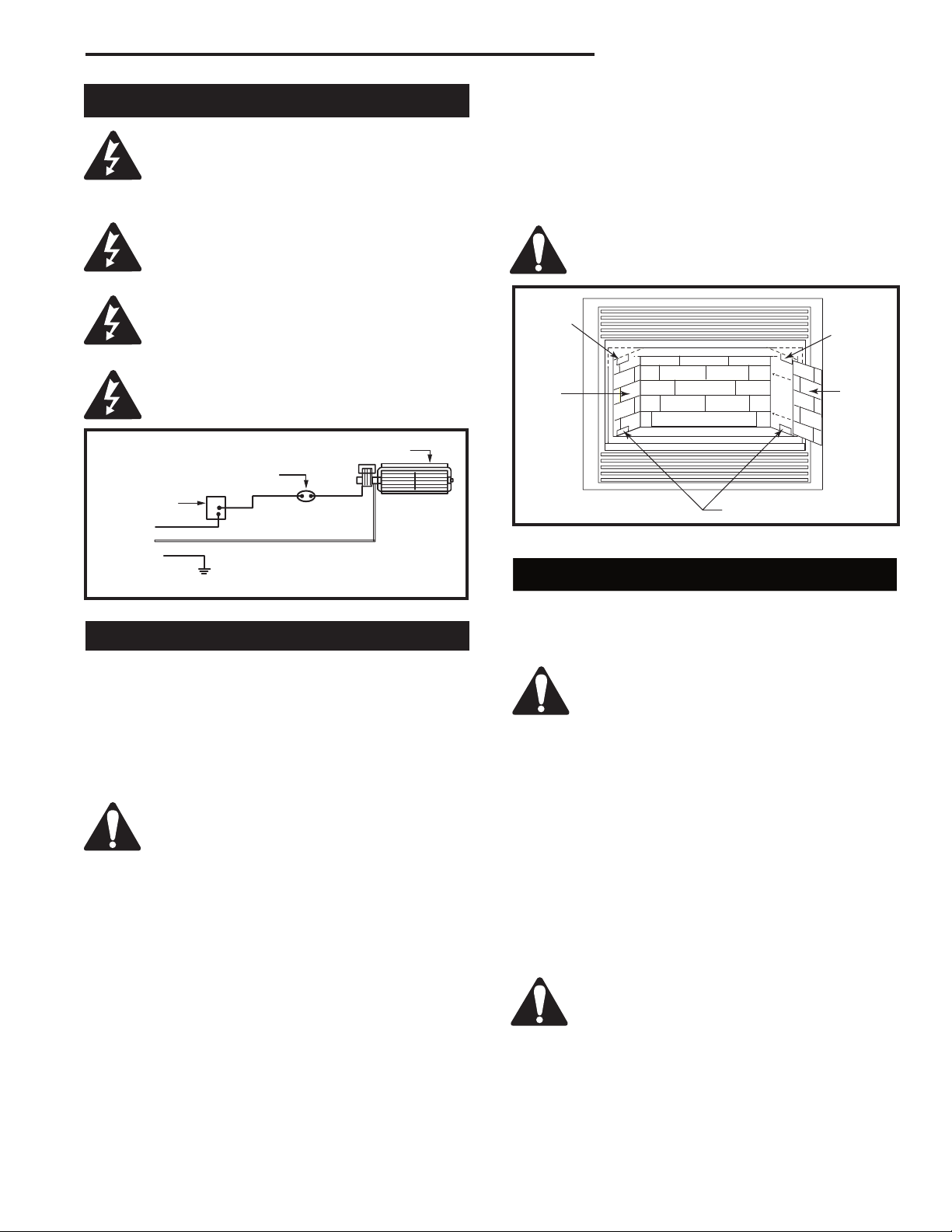
RDVN Series Direct Vent Gas Fireplace
Black
White
Ground
The fireplace, when installed, must be
electrically connected and grounded in
accordance with local codes or, in the
absence of local codes, with the current
CSA C22.1 Canadian Electric Code.
For USA installations follow the local
codes and the national electrical code
ANSI/NFPA No. 70.
Should this fan require servicing or repair
the power supply must be disconnected.
For rewiring of any replacement parts refer
to Figure 59.
Any electrical re-wiring of this fan must be
done by a licensed electrician.
Temperature Sensor
Speed Control
Wiring Instructions
Fan
5. Place the rear refractory panel in place.
6. Slide the side refractory panels into place to hold
the rear panel secure. Adjust the top adjustable tabs
to hold the side panel against the firebox wall and
secure the tab. Repeat the procedure on the other
side.
7. Replace the logs and window frame assembly.
For esthetic purposes we recommend
lining up the horizontal mortar lines.
Adjustable
Tab
Side
Panel
FP1231
Fig. 60 Ceramic panel installation.
Back Panel
Lower Side Supports
Adjustable
Tab
Side
Panel
FP1025
Fig. 59 FK24 fan wiring.
Ceramic Refractory Kits
Ceramic refractory panels are available in kit form for
the RDV/TDV series appliances.
Appliance Model Kit Name
33RDV AT1CBB
33TDV AT1CBB
36RDV/TDV BT2CBB
39RDV/TDV CT2CBB
Take care when handling the refractory
panels as they are fragile until held in
place and supported.
NOTE: The bottom pieces supplied in ceramic
refractory kit are not used on these fireplaces.
Installation, refer to Figure 60
1. Remove the front window frame assembly.
2. Remove the logs.
3. Place the lower supports for the side refractory
panels on the base of the firebox. Place each
support so the slotted hole fits over the forward
screw head along the edge of the base.
4. Loosely attach the top adjustable tabs to the studs
located in the top of the firebox toward the front
corners.
Discard small angular panels.
Decorative Bay Windows
Bay window kits are available for the 33TDVN/33RDVN,
36TDVN/36RDVN & 39TDVN/39RDVN model
appliances.
When fitting the Bay Window Kits the
original window frame assembly must
remain in place. The Bay Window kit will fit
over the existing window frame assembly.
Installation
1. Remove the existing bottom louvre assembly
complete with the hinges.
2. Remove the top louvre assembly.
3. Assemble the Bay Window Kit according to the
instructions supplied with the kit.
4. Place the 2 pieces of ceramic refractory along the
base of the bay window. (Fig. 61)
5. Hang the Bay Window Assembly over the existing
window frame assembly.
6. Re-install the upper louvre assembly.
Do not remove the existing window frame
assembly.
20007628
39

RDVN Series Direct Vent Gas Fireplace
Top Louvre
Bay
Window
Frame
Ceramic
Refractory
Bottom
Brass Trim
Screws
Fig. 61 Bay window installation.
Ceramic
Refractory
Bottom
Louvre Assemblies
FP1234
Bay Window Screen
Bay Window Screen Kits are available for the 33RDVN,
36RDVN & 39RDVN model appliances.
Do not remove existing window frame
assembly! Remove all plastic from brass
trims.
1. Let the fireplace cool down if it has been operating.
2. Remove existing top louvre from fireplace by lifting
up and pulling out.
3. Hang Bay Window Screen Frame Assembly over top
of existing window frame assembly.
CFM178
Fig. 62 Bay window screen assembly.
Remote Controls
Optional remote control units are available to control
different functions of the appliances
Model Function/s Controlled
RCI ON/OFF
RC2 ON/OFF and Temperature
IMTFK Wall mounted thermostat control
40
20007628

RDVN Series Direct Vent Gas Fireplace
20007628
41

RDVN Series Direct Vent Gas Fireplace
42
20007628

RDVN Series Direct Vent Gas Fireplace
20007628
43

RDVN Series Direct Vent Gas Fireplace
Limited Warranty
TEMCO Fireplace Products Direct Vent Gas Fireplaces
This warranty is limited to CFM Fireplace Products
Direct Vent Gas Fireplaces (henceforth, Product) manufactured by CFM Corporation (henceforth, CFM).
ONE YEAR WARRANTY
CFM warrants all components of the Product to be free
of defects in materials and workmanship for a period of
one year from the date of installation, with the exception
of the warranty on logs and ember base. If, by the sole
determination of CFM, any component covered under this
warranty is found to be defective, CFM will, at its option,
repair or replace the defective component at no charge
and will pay labor cost incurred as specified in the current
CFM Labor Allowance Schedule, 71313. If CFM determines replacement or repair is not economically practical,
CFM will, at its option, refund the purchase price of the
Product. Date of installation and purchase price must be
verified by acceptable proof of purchase.
This warranty covers only parts and labor as provided
above. In no case shall CFM be responsible for materials,
components or construction which are not manufactured
or supplied by CFM, or the labor necessary to install,
repair or remove such materials, components or construction.
NOTE: If allegedly defective components need to be returned by CFM in connection with the above warranties,
frieght or postage charges must be prepaid.
QUALIFICATIONS
For the above warranties to apply:
The Product must be installed by a qualified installer;
strictly in accordance with CFM installation instructions, and in compliance with local codes and ordinances. The logs must be placed strictly in accordance
with the arrangement described in the installation instructions.
The Product must be operated and maintained according
to the instructions furnished. Alteration of the Product
in any way is prohibited and voids any and all warranties. Removal of the data plate alters the Product
and voids the warranty.
The installer must have completed the installation
and Startup Checklist, a copy of which must be submitted along with proof of purchase, to obtain prior
approval for warranty repair or replacement and to
affect a warranty claim. The Checklist is found on
Pages 41 and 42 of this manual.
The limited warranty applies only to the original owner of
the Product or the original owner of the dwelling in which
the Product was installed. Use of any parts other than
genuine factory provided replacement parts shall void
this warranty.
Limitations
CFM is not responsible for any incidental or consequen-
tial damages caused by possible defects in the Product.
The duration of any implied warranty with respect to the
Product is limited to the duration of the foregoing warranties.
CFM is not responsible for any warranty repair (material
or labor) for defects created by improper field conversions.
Some states and provinces do not allow exclusion of incidental or consequential damages or limits on the duration
of implied warranties, so these limitations may not apply
to you.
Warranty Fulfillment
Claims require specific agreement and consent from
CFM Technical Services prior to performing any warranty repair or replacement. CFM reserves the right
to investigate any and all warranty claims. The ap-
pliance must not be removed prior to such investigation
other than on direction from CFM.
Please provide the following information when communicating with CFM Technical Services, its Dealers or
Distributors regarding service under this warranty.
CFM reserves the right to decide on the method of settlement (if any). This limited warranty is given in lieu of any
other expressed or implied warranty, and supersedes all
other CFM Product warranties.
Model Number: ____________________
Serial Number: _____________________
Date of Installation: ____/____/____
Purchased From: ___________________
44
20007628

RDVN Series Direct Vent Gas Fireplace
TEMCO FIREPLACE PRODUCTS DIRECT VENT FIREPLACES
INSTALLATION AND STARTUP CHECKLIST
Customer Copy
NOTE: TEMCO Fireplace Products gas logs and fireplaces require installation by a qualified gas appliance installer.
A copy of this checklist must be submitted, along with proof of purchase, when applying to Technical Services for prior
written approval of warranty repair or replacement.
❑ Read and understand installation instructions before attempting installation.
Verify CORRECT FUEL TYPE
❑ Check carton model number.
❑ Check fireplace label. Models ending in N are for natural gas; those ending in P are for propane (LP gas).
WARNING: Using the incorrect fuel can create a serious fire hazard and will void the warranties. Install in
accordance with local and/or natonal codes and ordinances. Follow the TEMCO installation instructions.
❑ Supply service shutoff valve upstream of gas fireplace.
❑ Gas line size adequate for input rating (BTU’s per hour) of fireplace, per National Fuel Gas Code (NFPA54)
in the case of USA installations or Installation Code CAN 1-149 in the case of Canadian installations.
Make following checks:
❑ Gas line integrity at supply line connection.
❑ Glass front panel position.
❑ Correct gas pressure. Inlet Pressure __________(inches w.c.) Manifold Pressure __________(inchesw.c.)
❑ Piezo ignitor function (millivolt control models only).
❑ Pilot ignition.
❑ Main burner ignition.
❑ Proper flame pattern and color.
❑ Positioning of logs (in accordance with instructions).
❑ Clearances to combustibles (vent, framing, mantels, etc.).
❑ Vent system in compliance with instructions. All joints and connections sealed.
❑ Wall switch operation. Do not connect millivolt wiring, wall switch or valve to 120v line voltage unless units is
specifically DSI equipped.
❑ Demonstrated proper operating procedure to homeowner.
❑ Explained the need for proper cleaning and maintenance.
❑ Check all fittings and connections for gas leaks, correct if necessary.
Please sign below that checklist has been completed and understood. DATE INSTALLED ____/____/____
Installer Phone Consumer Phone
20007628
45

RDVN Series Direct Vent Gas Fireplace
TEMCO FIREPLACE PRODUCTS DIRECT VENT FIREPLACES
INSTALLATION AND STARTUP CHECKLIST
Installer’s Copy
NOTE: TEMCO Fireplace Products gas logs and fireplaces require installation by a qualified gas appliance installer.
A copy of this checklist must be submitted, along with proof of purchase, when applying to Technical Services for prior
written approval of warranty repair or replacement.
❑ Read and understand installation instructions before installing.
Verify CORRECT FUEL TYPE
❑ Check carton model number.
❑ Check fireplace label. Models ending in N are for natural gas; those ending in P are for propane (LP gas).
WARNING: Using the incorrect fuel can create a serious fire hazard and will void the warranties. Install in
accordance with local and/or national codes and ordinances. Follow the TEMCO installation instructions.
❑ Supply service shutoff valve upstream of gas fireplace.
❑ Gas line size adequate for input rating (BTU’s per hour) of fireplace, per National Fuel Gas Code (NFPA54) in
the case of USA installations or Installation Code CAN 1-149 in the case of Canadian installations.
Make following checks:
❑ Gas line integrity at supply line connection.
❑ Glass front panel position.
❑ Correct gas pressure. Inlet Pressure __________(inches WC) Manifold Pressure __________(inchesWC)
❑ Piezo ignitor function (millivolt control models only).
❑ Pilot ignition.
❑ Main burner ignition.
❑ Proper flame pattern and color.
❑ Positioning of logs (in accordance with instructions).
❑ Clearances to combustibles (vent, framing, mantels, etc.).
❑ Vent system in compliance with instructions. All joints and connections sealed.
❑ Wall switch operation. Do not connect millivolt wiring, wall switch or valve to 120v line voltage unless units is
specifically DSI equipped.
❑ Demonstrated proper operating procedure to homeowner.
❑ Explained the need for proper cleaning and maintenance.
❑ Check all fittings and connections for gas leaks, correct if necessary.
Please sign below that checklist has been completed and understood. DATE INSTALLED ____/____/
____
Installer Phone Consumer Phone
46
20007628

Customer Copy
RDVN Series Direct Vent Gas Fireplace
Model # ______________________________________
I certify that I have followed all codes and regulations and adhered to the TEMCO Fireplace Products installation
instructions. I have completed the proper installation and startup checklist.
Serial # ______________________________________
Installer’s Signature Print Installer’s Name
Purchaser _____________________________________
Address ______________________________________
_____________________________________________
Phone ________________________________________
Retailer _______________________________________
Address ______________________________________
_____________________________________________
Phone ________________________________________
Date of Purchase _______________________________
Please cut along dotted line
WARRANTY REGISTRATION
Please answer the following questions (Check Box):
1. Type of Home ❑ Single Family ❑ Duplex ❑ Apt.
❑ Mobile Home ❑ Cabin/Vacation
2. Installed in(Room) ❑ Living ❑ Family ❑ Great ❑ Rec
❑ Bedroom ❑ Other
3. Other Choices Considered: ❑ Vented Decorative Gas
Log/Fireplace ❑ Woodburning Fireplace
❑ Gas Insert ❑ Woodburning Insert
❑ Direct-Vent Gas Fireplace/Logs
4. Why did you choose Direct Vent? (Rank in order of
importance: 1-6)
___ Appearance ___ Location Flexibility
___ Builder Decided ___ Other
To register your warranty, please provide the information indicated on this form and mail it to:
TEMCO Fireplace Products
Attn: Warranty Registration
410 Admiral Blvd.
Mississauga, Ontario Canada L5T 2N6
Model # ______________________________________
I certify that I have followed all codes and regulations and adhered to the TEMCO installation instructions. I have
completed the proper installation and startup checklist.
Serial # ______________________________________
Installer’s Signature Print Installer’s Name
Purchaser _____________________________________
Address ______________________________________
_____________________________________________
Phone ________________________________________
Retailer _______________________________________
Address ______________________________________
_____________________________________________
Phone ________________________________________
Date of Purchase _______________________________
WARRANTY REGISTRATION
Please answer the following questions (Check Box):
1. Type of Home ❑ Single Family ❑ Duplex ❑ Apt.
❑ Mobile Home ❑ Cabin/Vacation
2. Installed in(Room) ❑ Living ❑ Family ❑ Great ❑ Rec
❑ Bedroom ❑ Other
3. Other Choices Considered ❑ Vented Decorative Gas
Log/Fireplace ❑ Woodburning Fireplace
❑ Gas Insert ❑ Woodburning Insert
❑ Direct-Vent Gas Fireplace/Logs
4. Why did you choose Direct Vent? (Rank in order of
importance: 1-6)
___ Appearance ___ Location Flexibility
___ Builder Decided ___ Other
20007628
47

Efficiency Ratings
Model EnerGuide Ratings
Fireplace Efficiency (%)
33RDVN 48.4
33RDVP 48.4
36RDVN 48.9
36RDVP 48.9
39RDVN 56.5
39RDVP 56.5
CFM Corporation
2695 Meadowvale Blvd. • Mississauga, Ontario, Canada L5N 8A3
800-668-5323 • www.cfmcorp.com
 Loading...