


T30 SERIES PID Controller
User's Manual
DIGITAL PID CONTROLLER
SERIES
T30
PID controller + Timer
Hybrid

Useful Features !
※
Use the menu return function to speed up
the setting up to 10 times faster.
If you press the up key
while pressing the set key
in any setting menu,
you can move to the
corresponding upper menu
and move to the desired menu immediately.
+
F
u
n
c
t
i
o
n
o
f
m
e
n
u
r
e
t
u
r
n
sEt.n
< General Setting
group >
ORG.1
< Initial setting group >
iosE.2
< Input.output
Setting group >
Enhance hot key between
group menus

www.temcoline.com
DIGITAL PID CONTROLLER
Thank you for purchasing the T30 series from Temcoline.
The T30 series is a precision industrial controller that uses an advanced
2 degree-of-freedom (DOF) algorithm.
The T30 series consists of 5 models, which are T32, T33, T34, T37, and
T39.
This manual explains the installation, the functions, the operation, and
the handling of the products.
Please read the manual thoroughly before using the products.
If any difculties arise while using our products, please call our customer
service at +82-1588-5439.
- Use the products under the conditions specied in this manual.
- Please heed the cautions and warnings listed in this manual.
- The contents of the manual may be changed without notice.
- The product is designed to be used installed on a control panel.
- This manual is copyrighted, and may not be copied in part or in
whole without permission.
-
The manufacturer takes no responsibility for direct or indirect damages
caused by careless operation or operation under unpredictable or
risky environments.
Safety requirements are intended to prevent accidents and dangers
through the proper use of the products, so please heed them at all times.
The safety requirements are divided into "cautions" and "warnings",
which
indicate the following.
Serious injury or death may be caused
if instructions are not observed.
Failure to observe these instructions
may cause damage to the instrument
or some injury to the user.
2
Pay attention to the followings!
Safety requirements!
WARNING
CAUTION

www.temcoline.com
DIGITAL PID CONTROLLER
Use a separate safety device when this product is used to control a device
that could harm lives or expensive property in the event of a malfunction or a
breakdown. (This may cause res, deaths, or damage to property.)
Please conduct an inspection when water has entered the product.
(It may cause short circuits, res, and malfunction.)
Do not use this controller at place where there are flammable or
explosive gas. (It may cause a re or explosion.)
This controller should be used indoors.
(It may shorten the controller's life or give an electric shock.)
Before turning the power on, please check that wiring is correct to the
number of terminal. (It may cause a re.)
Observe the rated voltage and specication.
(It may cause a re or shorten the controller's life.)
Turn off the power during wiring and maintenance to avoid an electric shock.
Be careful that any of foreign materials do not inow into the controller. (It
may cause a re or malfunction of the controller.)
Do not touch the terminals when it is power on. (It may give an electric
shock.)
Do not give direct vibration or shock to the controller.
(It may cause of malfunction of the controller.)
This controller must be mounted on the panel to avoid an electric
shock.
Do not use chemical detergent or solvent, but use a dry towel in cleaning
the controller.(It may cause an electric shock or a re.)
Do not attempt to disassemble, modify and repair.
Please check the polarity of power before wiring and connecting the sensor. (It
may cause an electric shock or explosion.)
1.
1.
2.
2.
3.
3.
4.
4.
5.
5.
6.
6.
7.
7.
3
WARNING
CAUTION

www.temcoline.com
DIGITAL PID CONTROLLER
1. Ordering Information
2. Input ranges & Output conguration
3. Dimensions & Panel cutouts
4. Terminal Arrangements & Wirings
5. Ratings & Specications
6. Features & Function
7. Check points before using
8. Initial installation & Min. operation procedures
9. Entering into "set menu" & Setting method
10. Flow chart (Parameter structure)
11 . Setting mode
12. Alarm(ALARM1, 2, 3) setting
13. Details explanation of primary function
1) Auto tuning(AT) function
2) Manipulated variable(Mvn) check mode
3) Alarm(ALARM1, 2) function
4) Retransmission output
5) Input function
6) Selection function for Hysteresis
7) SV1, 2 set up control by external contact signal
8) Set value "LOCK" function
9) Error indication during operation
14. SOAK alam and Timer output
1) SOAK alam and Timer output
2) Timer Normal, T1~5 Output operation timing chart
5
16
28
9
18
30
32
14
27
22
7
17
29
12
27
21
31
32
32
32
32
33
15
27
25
Contents
4

www.temcoline.com
DIGITAL PID CONTROLLER
Code
Model
Code
2
3
4
7
9
S
Model
Code
Description
Size
Description
Remarks
Remarks
Remarks
T32-SERIES
SINGLE : Standard
Heating or Cooling control
T33-SERIES
T34-SERIES
T37-SERIES
T39-SERIES
48(W) x 96(H) x 77(D)
No option (Basic function)
No option (Basic function)
Option : 0, 1, 3
Option : 0, 3
No option (Basic function)
96(W) x 48(H) x 77(D)
96(W) x 96(H) x 77(D)
48(W) x 48(H) x 77(D)
72(W) x 72(H) x 77(D)
1. Ordering Information
1)
(1) Size
(3) Optional function
(2) Control mode
T32, T33
SERIES
T34
SERIES
T37
SERIES
T39
SERIES
0
RELAY output 1, Alarm output 2,
SCR(4~20mA), SSR(Voltage pulse) 1,
RET(4~20mA Retransmission output)
D.I(SV2, 3) External input
RELAY output 1, Alarm output 2,
SCR(4~20mA), SSR(Voltage pulse) 1,
RET(4~20mA Retransmission output)
D.I(SV2, 3) External input
RELAY output 1 (ALARM or MAIN),
SCR(4~20mA), SSR(Voltage pulse) 1
RELAY output 1, Alarm output 2,
SCR(4~20mA), SSR(Voltage pulse) 1
No function
(Basic function S0x)
No function
(Basic function S0x)
Basic function +
Option code
(0 : No option)
Basic function +
Option code
(0 : No option)
Ex.) T34-S10
Ex.) T34-S30
Ex.) T37-S30
RET(4~20mA Retransmission), Alarm 2
D.I(SV2, 3) External input, Alarm output 2
D.I(SV2, 3), RET(4~20mA Retransmission)
0
0
0
1
3
3
5
(1)
Size
(3) Optional function
(2) Control mode
(4) Power supply voltage
T 3 -

www.temcoline.com
DIGITAL PID CONTROLLER
Code
0
1
Description
Remarks
100 ~ 240 V AC
Alternating or Direct current usage
General-purpose usage
24V AC or DC
2) Example of model building
(4) Power supply voltage
6
"4"
"S"
"0"
"0"
T34-S00
"7"
"S"
"3"
"0"
T37-S30
Ex.) T34-S00
Ex.) T37-S30
(1)
Size : 48(W) x 48(H) x 77(D)
(1)
Size : 72(W) x 72(H) x 77(D)
(3) Optional function : Basic function
(3) Optional function : DI(SV1,2), RET
(2) Control mode : SINGLE
(2) Control mode : SINGLE
(4) Supply voltage : 100~240V AC
(4) Supply voltage : 100~240V AC
www.temcoline.com
DIGITAL PID CONTROLLER
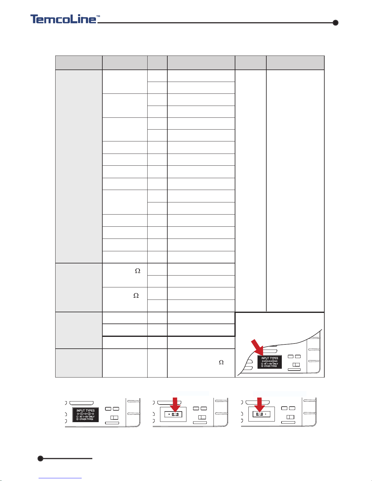
2. Input ranges and Output configuration
1) Input ranges
※ The T30 series has multiple inputs, which may be set and changed by the user.
7
※ How to change the interior switch when using 1~5V input
* F.S is max. value
to min. value of
each range.
* Digit is minimum
of display.
K
J
E
T
R
B
S
L
N
U
C (W5)
D (W3)
0~100 mV DC
-10~20 mV DC
1~5 V DC
4~20 mA DC
1
2
15
16
3
4
5
6
7
8
17
9
10
12
13
20
22
21
23
33
32
30
30
11
±0.3% of
F.S + 1 Digit
Voltage
(V DC/mV DC)
-200 ~ 1370
-199.9 ~ 999.9
-200 ~ 1000
-199.9 ~ 999.9
-200 ~ 1000
-199.9 ~ 999.9
-199.9 ~ 400.0
0 ~ 1700
400 ~ 1800
0 ~ 1700
-200 ~ 900
-199.9 ~ 900.0
-200 ~ 1300
-199.9 ~ 400.0
0 ~ 2300
0 ~ 2400
-199.9 ~ 500.0
-200 ~ 500
-199.9 ~ 640.0
-200 ~ 640
0 ~ 100 mV DC
-10 ~ 20 mV DC
1~5 V DC
When using current input,
use the resistor 250 on
input terminal.
Input type
Input
Setting
Code
Temperature range
Remarks
Accuracy
Thermocouple
(T.C)
RTD
Current
※ When using 1~5V input
(30), the interior jumper
switch must be relocated.
①
Remove plate or take out
the main cover.
②
Move and insert the
jumper that pulled by
tweezers.
③
Relocated jumper as
above and attach plate
or mounted cover.
MULT-IN MODE
IN 1~5V ONLY MODE
JPt100
(JIS, KS)
Pt100
(DIN, IEC)

www.temcoline.com
DIGITAL PID CONTROLLER
2) Output
conguration
(1) Summary and explanation of output settings
General
type
Setting
number
OUTPUT-1
OUTPUT-1 (ALARM 1,2)
T30-SXX
0
1
2
3
Relay output
SSR output
AL1 output AL2 output
SSR/SCR OUTPUT
SCR output
SCR output
OUT(ON/OFF)
ALM3(ALM1)
ALM3(ALM1)
ALM3(ALM1)
ALARM1 ALARM2
RET
RET
RET
RET
-
-
-
-
ALM3(ALM1)
OUT(PID)
OUT(PID)
OUT(PID)
※
The gure on the left uses
the terminal socket of
T37-S30 as an example
to illustrate the output
response relationship
.
Relay output of ON/OFF control [ Output setting number : 0 ]
This is a simple on/off control, mainly used to control cooling devices.
SSR output of PID control (Voltage pulse) [ Output setting number : 1 ]
This is the most widely used setting, and the default value at the point of manufacture.
SCR output of PID control (4~20mA current output) [ Output setting number : 2 ]
This setting is used mainly with thyristor power regulator (TPR) modules,
and is capable of precision control.
Relay output of PID control [ Output setting number : 3 ]
This is the most cost-efcient method of implementing PID control and is used mainly
with magnetic switches (electric switches). However, it may wear the contact point,
and is difcult to use in places that require fast response.
1(SSR) or 2(SCR)
0(ON/OFF)
or 3(RELAY)
Control output
Control output
The T30 series
has multiple outputs.
8
※ It is only for T34-S00!
ALARM1 or
3 output
ALARM1 or
3 output
(2) Main relay control output and alarm output
The T30 series can use up to three alarms independently when using the control
output as SSR (1) or SCR (2). That is, the basic model (no option) can be used as
alarm 1, and the optional model (alarm output) can be used as alarm 3.

www.temcoline.com
DIGITAL PID CONTROLLER
3. Dimensions and Panel cutouts
1) T32 (48x96 mm) Dimensions
2) T33 (96x48 mm) Dimensions
3) T34 (48x48 mm) Dimensions
9
T32 / T33 (96x48)
Panel cutouts
(Unit: mm)
(Unit: mm)
45
±0.5
92
±0.5
Min. 30
Min. 20
T34 (48x48) Panel cutouts
Min.17
Min.17
45
+0.5
-0
45
+0.5
-0
48.0
96.0
10.0 77.0
96.0
91.0
96.0
48.0
48.0
43.6
10.0
77.0
8.8
48.0
44.9
48.0
77.0
48.0

www.temcoline.com
DIGITAL PID CONTROLLER
4) T37 (72x72 mm) Dimensions
5) T39 (96x96 mm) Dimensions
10
(Unit: mm)
(Unit: mm)
T37 (72x72) Panel cutouts
Min. 20
68
±0.5
68
±0.5
Min. 30
T39 (96x96)
Panel cutouts
Min. 20
92
±0.5
92
±0.5
Min. 30
72.0
9.0 77.0
72.0
67.0
72.0
96.0
77.0
96.0
91.0
10.0
96.0

www.temcoline.com
DIGITAL PID CONTROLLER
6) Installation
(1) T34-SERIES
(2) T32 / T33 / T37 / T39-SERIES
①
Bore a hole in the panel, referring to the panel cutouts on the previous page.
② Insert this device into the front of the panel.
③
After inserting two brackets into the holes on the left and right respectively
of the device, Slide it forward until it ts tightly to the panel and secure.
①
Bore a hole in the panel, referring to the panel cutouts on the previous page.
② Insert this device into the front of the panel.
③
Insert 2 brackets, one each on the B/K holes on the top and the bottom
of the device.
④ Secure using screws on the two locations at top and bottom.
11
[ gure 1 ] Top side [ gure 2 ] Bottom side
[ gure 3 ] Fixing completion
Hole of xing screwHole of xing screw
Bracket hole
Bracket hole
Turn the screw
2-3 times after
contact with panel.
Bracket hole
Panel Panel

www.temcoline.com
DIGITAL PID CONTROLLER
4. Terminal arrangements and Wirings
1) T32 (48x96 mm), T33 (96x48 mm)
2) T34 (48x48 mm
)
12
T32, T33
T34
Option 1
(T34-S1x)
Option 3
(T34-S3x)
OPTION
T32/33
T37
T39
N.C

www.temcoline.com
DIGITAL PID CONTROLLER
T37
T39
T39
3) T37 (72x72 mm)
4) T39 (96x96 mm)
※ Terminal explanation (T39-S00)
Terminal :
OUT1 only for output
selection no. 0, 3 (Relay output) mode.
Terminal
: OUT1 only for output.
selection no. 1, 2 (SSR, SCR output) mode.
Terminal :
RET(Retransmission 4~20mA)
or for power of sensor SPS. (DC 15V)
Terminal :
Power supply terminal.
Terminal :
Alarm1 output terminal.
Terminal :
Alarm2 output terminal.
Terminal : The external D.I input
terminal may be used when (DIS=ON), and
the target value may be controlled. (SV1, SV2)
Terminal : Input terminals.
13
OPTION
Option 3
(T37-S3x)
T37
T39
T39
N.C

www.temcoline.com
DIGITAL PID CONTROLLER
5. Ratings and Specifications
T30-SERIESModel
Power supply
Power consumption
Display Accuracy
Control
Output
Relay
Voltage
(S.S.R)
Current
(S.C.R)
Input Impedance
Input sampling period
Control Method
Multi SV Input (D.I)
Retransmission Output
Ambient temperature
and Humidity
Weight
(Bracket, Accessories included)
Input Type
5VA (Max.)
±0.3% of FS +1 Digit
50~250ms (variable according to SG-PID algorithm)
DC15V 25mA (built-in short protection circuit)
Voltage pulse (time proportional PID output)
4~20mA DC, load impedance ≤ 600
(continuous PID output)
Super 2 degree-of-freedom PID (SG-PID algorithm),
Auto-Tuning
ON : ≤ 1K
, OFF : ≥ 100K
(external control SV1,2)
TC: K, J, T, E, R, B, S, L, N, U, C(W5), D(W3)
Platinum RTD: KPt100(KS), JPt100(JIS), Pt100(DIN)
Current input(A): 4~20mA DC
Voltage input(V): 1~5V DC, -10~20mV DC, 0~100mV DC
Rating 100~240V AC 50~60Hz (voltage operating range: 85~265V AC)
※
Option: Rating 24V AC or DC (voltage operating range: 20~28V DC)
1c 250V AC, 3A(resistance load) electric lifespan ≥ 100,000
(time proportional PID output or ON/OFF output)
4~20mA DC, load impedance ≤ 600
resolution 1/4,600
PV(process value), SV(set value), MV(manipulated variable[%]),
SPS(sensor module power supply)
Alarm output
(Alarm 1,2,3)
ALARM 1
ALARM 2
ALARM 3
1a 250V AC 3A (resistance load) 20 type of independent event
output & Control loop break alarm
Convenient timer output 6 types (SOAK ALARM external timer
mode T1 to T5) Inverter operation (RUN) / stop (STOP)
control
T32, T33, T37 : 230g T34 : 140g T39 : 320g
+ 30g, if options are added
14
-10~50 / relative humidity 25~85% RH
(but with neither condensation nor freezing)
℃
※
Current input (250
), Voltage input (TC included) ≥ 1M
(RTD line resistance : ≤ 10
, when 3-line resistance are the same)

www.temcoline.com
DIGITAL PID CONTROLLER
6. Features and Function (ex. T34 SERIES)
※
Description
Name
Function
① Process value
① Process value (PV)
display (Red color)
② Auto tuning lamp
② Auto tuning (AT) lamp
③ Set value display
③ Set value (SV)
display (Green color)
④ Control output lamp
④ Control output lamp
⑨ Set value Down key
⑧ Shift key
⑦ Storage & Function key
⑤ SV2 display lamp
⑤ SV2 display lamp
⑩ Set value Up key
⑥ Alarm output lamp
⑥ Alarm output lamp
⑦
Function key
⑧
Shift key
⑨ Set value down key
⑩ Set value up key
Display the process value. (red color)
Flash every 0.5 second during auto tuning.
Display the set value, codes, and modes.
Lights when the control output is ON.
Lights when the SV2 is displayed.
Lights during the alarm is ON.
Use to shift the digits.
Use to decrease set value and to move the menu.
Use to increase set value and to move the menu.
Use to move the menus, to store, and to operate.
15

www.temcoline.com
DIGITAL PID CONTROLLER
7. Check Points before Using
1) Default values at the point of manufacture
2) 7 Segment display indications
3) Initial display on power supply (T34 SERIES basis)
Model Name
Firmware version display
Option indication
Output type indication
Input type indication
0 : Basic type (No option)
1 :
RET, ALARM1, 2
3 : DI(SV1, 2), ALARM1, 2
01 : K-Type (-200~1370 ℃)
02 :
K-type (-199.9~999.9 ℃)
33 : mV DC (0~100 mV)
16
The default input and output values of the product at the point of manufacture
are as follows.
Input : K-Type (Code No. 1) Output : SSR (Code No. 1)
0 : RELAY ON/OFF control
1 :
SSR (
VOLT-PULSE) PID control
2 : SCR (4~20mA) PID control
3 : RELAY PID control
※ When selecting SSR (1), SCR (2) output mode only for model T34-S00
(no option), alarm 1 is output as MAIN RELAY. For models with other alarm
options, alarm 3 is output as MAIN RELAY. (Refer to the page 8 for details)

www.temcoline.com
DIGITAL PID CONTROLLER
17
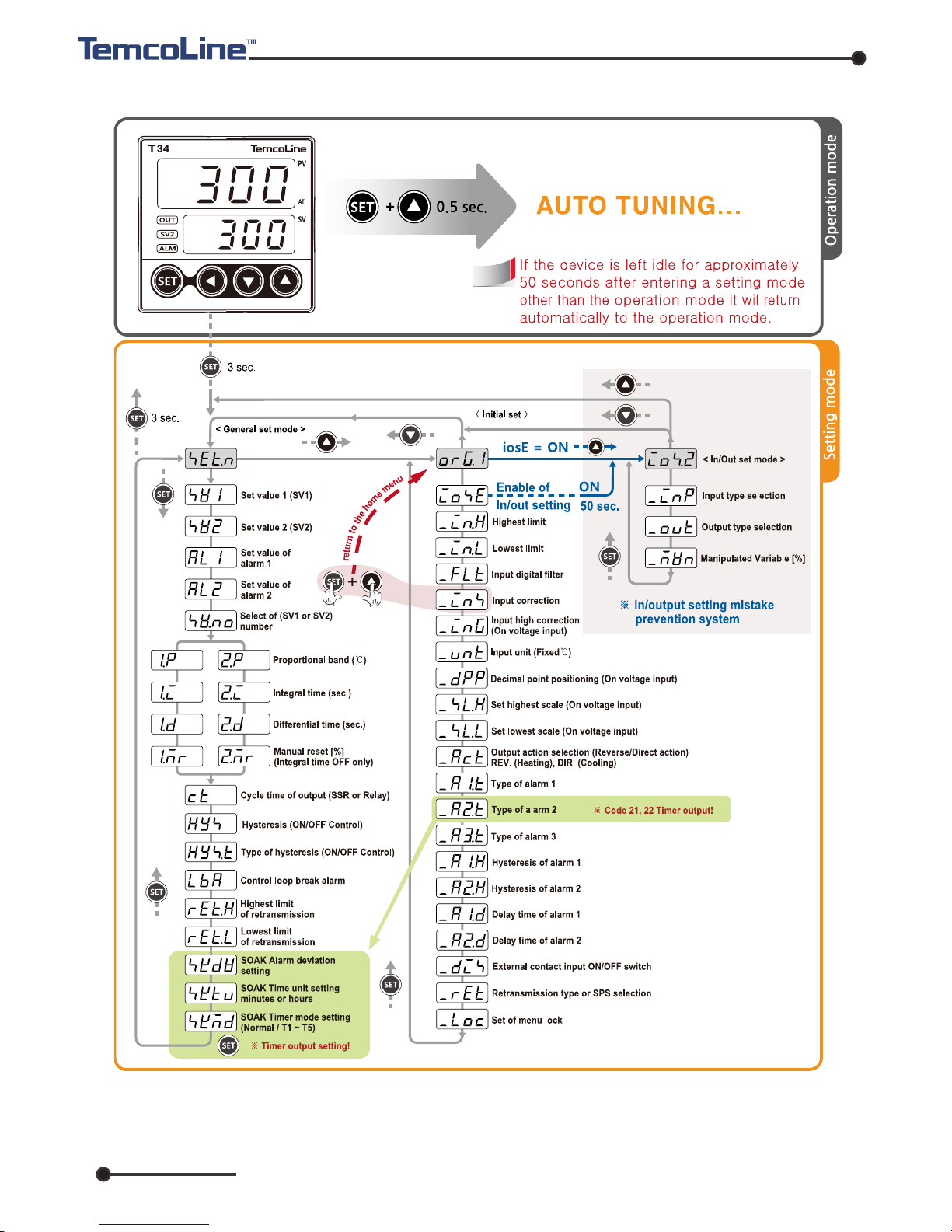
8. Initial installation and Minimum operation procedures
The following are the instructions for initial installation and minimum operation
procedures. Please read the contents of this manual, including the general functions
outlined here, as thoroughly as possible before operating the device.
1)
Check the external wiring diagram and specications.
(power supply and terminal
arrangement)
2) Check input and output specications!
The default setting for the T30 series at the point of manufacturer are as follows.
If you wish to change the input or the output type, please select the option
you
desire on the input group and the output group menus.
※ The input type settings must be congured rst before changes to other set values
are made.
When the input type is changed, all other parameters (set values) are reverted to
their factory default.
3) Select the desired set value (SV).
4)
Please set auto-tuning or P, I, D values to suit the operating environment.
Auto-tuning is recommended except under special circumstances.
Output : SSR mode (setting code 1)
Input :
K-Type (setting code 1 : -200 ~1370℃)
+
3초 이상
+
3초 이상
+
한번클릭
SET 키를 누른상태에서 UP 키를 한번 클릭하면
현재의 메뉴에 해당되는 처음의 위치로 순간 이동됩니다.
+
0.5초 이상5. : : 오토튜닝 단축 키
+
3초 이상
+
3초 이상
+
한번클릭
+
3초 이상
+
3초 이상
+
3초 이상
※ Direct menu navigation and entry key (hot key) support
T30 supports hot keys for user convenience.
4. One click :
Function of menu return, At any setting menu position,
if you press the UP key while holding the SET key, it moves
to the first position corresponding to the current menu.
3. 3 seconds or more : To enter initial setting mode
2. 3 seconds or more : To enter input/output setting mode
when AT is not running.
1. : To enter general setting mode
5. 0.5 seconds or more : Auto turning hot key
www.temcoline.com
DIGITAL PID CONTROLLER
18
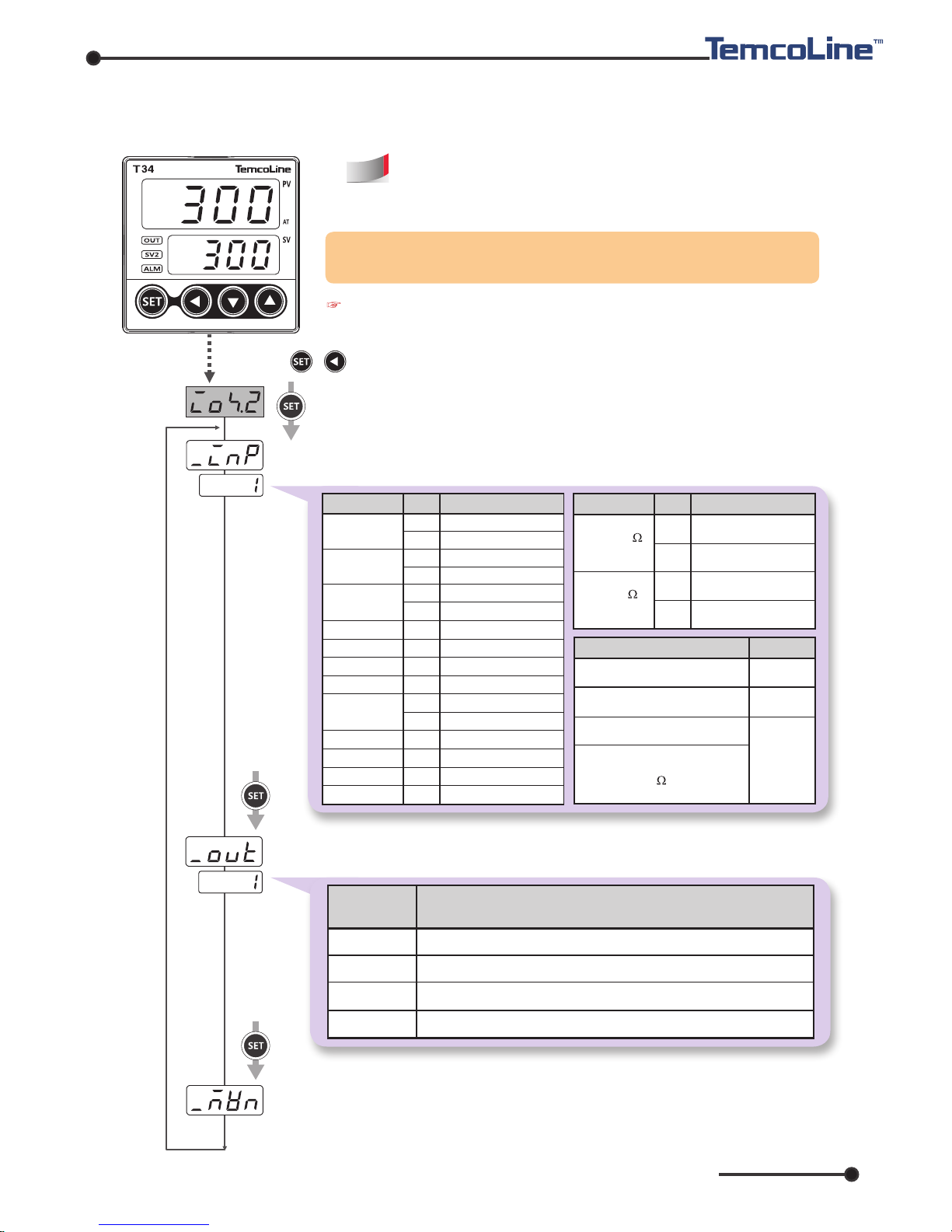
9. Entering into "set menu" and Setting method
1) Input & Output type setting
②
Input type setting : Select the desired input sensor type.
(setting code 1~33 / refer to P7, Input ranges)
③
Output type setting : Select the desired output type.
(setting code 0~3 / refer to P8, Output Conguration)
Temcoline products are universalized input and
output. Please set up input and output type rstly
and use when install our unit.
SETTING
CODE
CONTROL OUTPUT
RELAY ON/OFF CONTROL
SCR (4~20mA) P.I.D CONTROL
RELAY P.I.D CONTROL
SSR (Volt-Pulse) P.I.D CONTROL
0
1
2
3
④ Manipulated Variable Display setting [%]
It works when display the manipulated variable (0~100%) at
operating menu.
The method for input and output setting menu before
auto-tuning.
① Press + key more than 3 seconds, Entering into input & output setting menu.
※ Even if PID control output (1, 2, 3) is selected, ON / OFF control mode can
also be used when P value is OFF.
0 ~ 100 mV DC
-10 ~ 20 mV DC
1 ~ 5 V DC
33
32
30
INPUT(V DC/mV DC)
CODE
INPUT(RTD) TEMP. RANGE
20
22
21
23
-199.9 ~ 500.0
-200 ~ 500
-199.9 ~ 640.0
-200 ~ 640
CODE
INPUT(T.C)
CODE
TEMP. RANGE
K
J
E
T
R
B
S
L
N
U
C (W5)
D (W3)
1
2
15
16
3
4
5
6
7
8
17
9
10
12
13
11
-200 ~ 1370
-199.9 ~ 999.9
-200 ~ 1000
-199.9 ~ 999.9
-200 ~ 1000
-199.9 ~ 999.9
-199.9 ~ 400.0
0 ~ 1700
400 ~ 1800
0 ~ 1700
-200 ~ 900
-199.9 ~ 900.0
-200 ~ 1300
-199.9 ~ 400.0
0 ~ 2300
0 ~ 2400
JPt100
(JIS, KS)
Pt100
(DIN, IEC)
4 ~ 20mA DC
(Use 250 resistor.)
Caution !
When auto tuning is completed normally, the input / output menu is
locked for safety. Refer to the next page (P, 19) for how to How to Disable.

www.temcoline.com
DIGITAL PID CONTROLLER
19
2) The processing for input/output setting menu after auto-tuning
<Initial setting menu>
<In/output setting menu>
While normal using our products,
the method for input/output setting
menu after auto-tuning.
②
IOSE=ON
Return to the
operating menu.
(Will return
automatically)
①
+
more than 3 sec.
③ +
After auto-tuning has done of T30 series models, to avoid any user's mistake,
input/output setting menu is restricted automatically. But you can change input/
output by following ways. However, unit will be returned to factory default when
changed input type.
more than 3 sec.
※ Press + more than 3 seconds at the inital set. (before running auto-tuning)
※ Describe how to enter by using hot keys.

www.temcoline.com
DIGITAL PID CONTROLLER
20
3) Set value(SV) setting [ in condition of Mvn = OFF (basic) ]
4) Auto tuning
AT command lamp (flash every 0.5 sec.)
Auto-tuning is required before operating for the rst time. Set the target value(SV) in the
range
mainly used and run auto-tuning. When auto-tuning begins, the "auto-tuning command
lamp"
will ash every 0.5 second and will turn off upon completion of the auto-tuning
process.
Please refrain from operating the keys while auto-tuning is in progress.
① Enter to setting mode by key
② Set a desired value by key
③ Store a value by key
AT operation start : + 0.5 second
AT stop by perforce : + 0.5 second
※순간이동기능
< 초기설정 그룹 >
ORG.1
임의의 (위치)
설정 메뉴에서
SET키를 누른상태
에서 UP키를 누르면
해당되는 상위 (그룹)
메뉴로 순간이동하여 빠르게
원하는 메뉴로 이동할 수 있습니다.
+
편리한 기능
※ 순간이동 기능을
사용하면 설정속도가
최대 10배까지 빨라
집니다.
※
Function of menu return
※
Useful Features
※
Use the menu return function
to speed up the setting
up to 10 times faster.
If you press the up key
while pressing the set key
in any setting menu,
you can move to the
corresponding upper menu
and move to the desired menu immediately.
www.temcoline.com
DIGITAL PID CONTROLLER
21
10. Flow Chart (Parameter structure)
※ To enter 'Input/Output settings' by 'IOSE' on is valid for only time. If you want to enter
'Input/Output settings' again you must turn on 'IOSE' rst. If there is no Key action the
'IOSE' will be OFF automatically in 50 seconds.

www.temcoline.com
DIGITAL PID CONTROLLER
22
Initial value
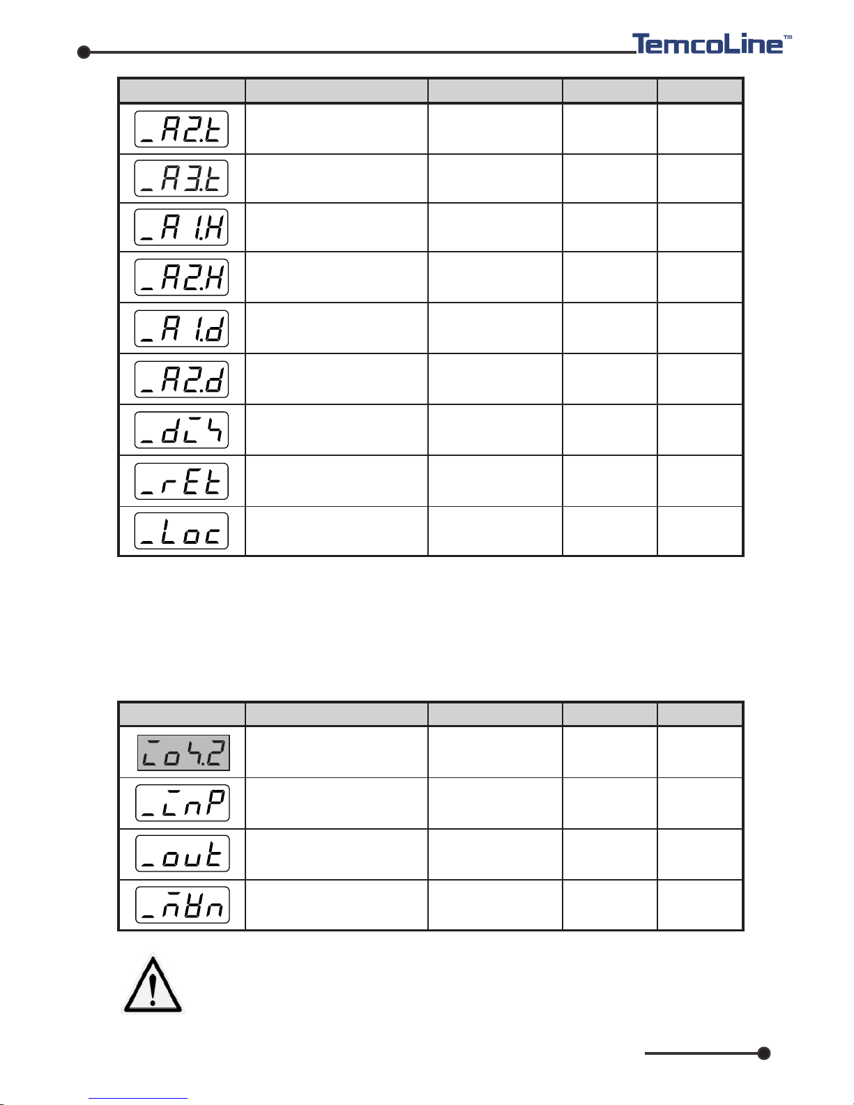
11. Setting mode
1) General setting mode
The general setting mode is for changing environment parameters on ad hoc basis and
also for tuning performance enhancement and conguring other functionalities.
Display
Description
Setting range
Condition
Display general setting
mode
EU (0 ~ 100 %)
EU (0 ~ 100 %)
EU (0 ~ 100 %)
EU (0 ~ 100 %)
1 / 2
EU (0 %)
EU (0 %)
EU (0 %)
EU (100 %)
20.0 ℃
240 sec.
2 sec.
2 ℃
NORMAL
480 sec.
EU (100 %)
EU (0 %)
1
50.0 %
60 sec.
D.I Option
in use
D.I Option
in use
Use Alarm 1
Integral time
OFF
PID control
(SSR or RELAY)
ON/OFF
control
ON/OFF
control
ALARM1
No. 21 selection
Use
retransmission
and select
PV or SV
Use Alarm 2
Always
PID control
PID control
PID control
- - -
OFF / 1 ~ 6000 sec.
OFF / 1 ~ 6000 sec.
-5.0 ~ 105.0 %
1 ~ 1000 sec.
EUS (0 ~ 100 %)
HALF / NORMAL
OFF / 1 ~ 9999 sec.
TC/RTD : _IN.H~_IN.L
DCV IN : _SL.H~_SL.L
( But, RET.H > RET.L )
Set value 1 (SV1) setting
Set value 2 (SV2) setting
Set value of alarm 1 (AL1)
Set value of alarm 2 (AL2)
Selection of (SV1, 2) number
SV1, 2 proportional band (P)
SV1, 2 Integral time (I)
SV1, 2 Differential time (D)
SV1, 2 Manual reset (MR)
Cycle Time (P.I.D Control Only)
Hysteresis (ON/OFF control)
Select the operational method
of Hysteresis
Control loop break alarm (LBA)
Highest limit of retransmission
(RET.H)
lowest limit of retransmission
(RET.L)
OFF/ 0.1 ~ 999.9 ℃
(ON/OFF control)
www.temcoline.com
DIGITAL PID CONTROLLER
23
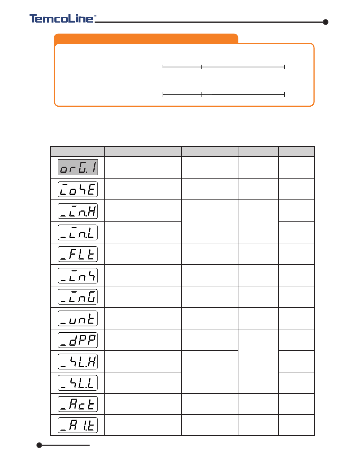
Initial value
2) Initial setting mode
The initial setting mode is for setting up initial parameters and conguration for
overall control and functionalities activation that are rarely changed after the initial
setup.
Display
Description
Setting range
Condition
Initial set mode (ORG.1)
ON / OFF
Within input range
(See input type and
range)
But, _IN.H
>
_IN.L
OFF / 1~120 sec.
EUS (-100.0~100.0 %)
EUS (-100.0~100.0 %)
OFF
1370
-200
EUS (0.0 %)
EUS (0.0 %)
OFF
℃
0.0
3
REV (Heating)
100.0
1
Always
Always
Always
Always
Always
Always
Always
On voltage
input
Voltage or
4~20mA
input mode
only
- - -
℃ / ℉
0 ~ 3
-1999 ~ 9999
But , SL-H > SL-L
Decimal point
positioning by _DPP
OFF / 1 ~ 21(LBA)
(See alarm type)
REV (Heating),
DIR (Cooling)
I/O setting entry switch
(IOSE)
Set highest input range
(_IN.H)
Set lowest input range
(_IN.L)
Set input digital filter value
(_FLT)
Input value correction (_INS)
Input temperature unit selection
(Fixed Celsius)
Correcting upper limit(Gain) of
input (_ING)
Select the decimal point position
in Voltage input mode (_DPP)
Free scale upper limit set
(voltage input mode)
Free scale lower limit set
(voltage input mode)
Select alarm 1 output type
Output action selection
※ EU :
An engineering unit in compliance with the input range
EU 0 % =
-
200
EU 100 % = 1370
-
200
1370 [℃]
0
EU 0 100 [%]
INPUT
ex) Input selection no. : 01 (K
-
TYPE)
EUS 0 100 [%]
( 0 )
( 200 )
( 1570 )
-
200
1370 [℃]
0 INPUT
EUS 0 % = 0
EUS 100 % = 1570
Ex.) Input selection no. : 01 (K-TYPE)
www.temcoline.com
DIGITAL PID CONTROLLER
24
Initial value
Initial value
Display
Display
Description
Description
Setting range
Setting range
Condition
Condition
In/output setting mode
OFF / 1 ~ 20
(See alarm type)
OFF / 1 ~ 20
(See alarm type)
1 ~ 33
(refer to P7, 2. 1)
0 ~ 3
(refer to P8, 2. 2)
EUS (0.0 ~ 100.0 %)
EUS (0.0 ~ 100.0 %)
OFF / ON
OFF / 1~240 sec.
OFF / ON
4
1
1
OFF
1 ℃
1 ℃
OFF
PV
OFF
OFF
OFF
OFF
Using alarm
1, 2 option
Using alarm
1, 2 option
Using alarm1
(1~20)
Always
Always
Always
Using alarm2
Using alarm1
Using
DI option
Using
RET option
Always
-
- -
PV/ SV/ MV/ SPS
OFF/ ON/ ALL
Select alarm 2 output type
Select alarm 3 output type
Input type selection (_InP)
Output type selection (_out)
Hysteresis of alarm 2 output
Hysteresis of alarm 1 output
Manipulated variable (_Mvn)
Display setting
Delay time of alarm 1
Delay time of alarm 2 and Timer
output, T4, T5 Time setting
External contact input (SV1, 2)
ON/OFF switch
Retransmission type
or SPS selection
Set data protection
3) In/Output setting mode
The input/output setting mode is a parameter for the rst time use. It's a
hardware configuration so requires special user caution. That is, the
configuration is determined by the type of equipment and it must be
congured rst. (※ all parameters are initialized according to the entered
input type.)
When the input type is changed, all parameters are reverted to their
factory
default. This means that before using the T30, the input type needs to
be set rst, after which other parameters can be configured.
If the input settings are changed while in use, auto-tuning and
other parameters need to be recongured.
When the input type is changed, all parameters are reverted to their factory default.
This means that before using the T30, the input type needs to be set first, after
which other parameters can be configured. If the input settings are changed while
in use, auto-tuning and other param eters n eed to be reconfigur ed.
Using alarm2
and Timer
OFF / 1 ~ 5999
sec.
Timer T4 and T5

www.temcoline.com
DIGITAL PID CONTROLLER
25
12. Alarm(ALARM1, 2, 3) Setting
Low
limit alarm
Alarm time!
(Holding!)
Process values
(PV)
Alam output!
Alarm output
Set value of alarm 1
Set value of alarm 2
<General set mode>
3 sec.
< General set mode >
3 sec.
3 sec.
or more
Loop break alarm
*Type of alarm 1 (When _A1.t = 21)
Type of alarm 1
Type of alarm 2
Type of alarm 3
Hysteresis of alarm 1
Hysteresis of alarm 2
Hysteresis of alarm 3
Delay time of alarm 1
Delay time of alarm 2
Alam1 type setting
< Initial setting menu >
Alam2 type setting
Alam 1 setting
Inverter start point
(0 ~ 100%)
6% set (operation start point)
<Initial set mode>
+ 3 sec.
The T30 series has up to three independent alarm outputs, and you can set up to 21
alarm types, hysteresis, and delay time.
The T30 series supports operation start / stop function during inverter control
(4 ~ 20mA) to enable more stable control and solve the problems of lifetime and
power saving of peripheral devices
When the low limit alarm is used, if
the temperature before the power
supply is lower than the set value,
unnecessary low limit alarm occurs
until the normal control temperature is
reached.
At this time, when the hold function
is used, it is possible to ignore the
occurrence of the alarm up to the
normal control temperature when the
initial power is turned on when the
temperature is within the alarm range.
2) Hold function
1) Inverter operation start / stop function
※
When the control output is selected as SSR (1) or SCR (2),
the main output relay can be used as alarm 3
Alam3 type setting " NO. 21"
(Inverter operation/stop output)
Inverter operation/stop output
Hysteresis
Hysteresis (2%)
Delay time(stop delay)
Power ON (HOLD)
Operates when using
the hold function

www.temcoline.com
DIGITAL PID CONTROLLER
26
2) Alarm output type and Selection code
When alarm type reverse-correspondence is selected for alarm type and code, please be
aware that when the alarm lamp turns on, the contact output will be off.
Loop break alarm (LBA)
ALARM 1
ALARM 3
ALARM 2
Inverter operation / stop
output alarm
Refer to page 28 LBA ! (ALARM1 only)
Page 25, 1) Refer to inverter operation stop control! (ALARM 3 only)
[Alarm No. 2 code 21] Supports five kinds of SOAK alarm and timer output (Process high)
(Setting mode T1 to T5)
[Alarm
No.
2 code 22] SOAK Alarm and Timer Output (Process low) refer to
* Page 33, "14. SOAK alarm and timer output mode ".
21
22
Absolute value upper-limit
Absolute value lower-limit
Upper-limit deviation
Process high with hold
Process high with hold
Process high with hold
Lower-limit deviation
Process low
Process low
Process low
Process low
Process low with hold
Process low with hold
Process low with hold
Process low with hold
Process high with hold
Upper & Lower-limit
deviation
Upper & Lower-limit
deviation with hold
Upper & Lower-limit
deviation in range
Upper & Lower-limit
deviation in range
with hold
CODE NO. ALARM TYPE
ALARM OUTPUT OPERATION
01
09
1 1
19
02
10
1 2
20
03
05
1 3
15
04
06
14
16
07
17
08
18
Low
When temperature
is falling
When temperature
is rising
OF F ON
ON
Alarm setting value
High
ON
Hy steresis
OF F
OF F
Low High
OF F
OF F
OF F
ON
ON
ON
Temperature
When temperature
is falling
When temperature
is rising
Alarm setting value
Hy steresis
<Negative temp. value setting>
Low
Temperature
When temperature is
falling
When temperature is
rising
High
OF F
OF F
OF F
ON
ON
-Alarm SV
-
ON
Hy steresis
<Positive temp. value setting>
Low
Alarm
setting value
High
SV
OF F
OF F
OF F
ON
ON
ON
Hy steresis
<Negative temp. value setting>
Low
Temperature
When temperature is
falling
When temperature is
rising
High
-Alarm
SV
OF F
OF F
OF F
ON
ON
-
ON
Hy steresis
Low High
SV
OF F
OF F
OF F
ON
ON
ON
Alarm
<Positive temp. value setting>
Hy steresis
When temperature
is falling
When temperature
is rising
AlarmAlarm
OF F
OF FON
ON
ON
ON
ON
ON
OF F
SV
Hy steresis
Temperature
Low High
When temperature
is falling
When temperature
is rising
AlarmAlarm
OF F
OF F
OF F
OF F
OF F
OF F
ON
ON
ON
SV
Hy steresis
Temperature
Low High

www.temcoline.com
DIGITAL PID CONTROLLER
27
13. Details explanation of primary function
Before the PID temperature controller can be used for the rst time, the P, I, D values
must be tuned. The auto-tuning function nds the optimal value by tuning automatically
according to the load factor and other conditions.
Please make sure that the controller is tuned before using it for the rst time, by dening
the set values in the most frequently used range and running auto-tuning.
When auto-tuning begins, the "auto-tuning command lamp" will ash every 0.5 second
and will turn off upon completion of the tuning process.
Please refrain from operating the keys while auto-tuning is in progress.
1) Auto tuning (AT) function
AT command lamp (ash every 0.5sec.)
※ Do not use auto tuning under below Process.
-
Rapid control Process such as Flow, input control.
-
Process which should not ON/OFF output even a temporary.
-
Process which should not over load at control.
2) Manipulated Variable [%] (Mvn) check mode
Refer to P18~19,
I/O Set Mode
Operation mode
< Setting method >
< In condition of Mvn = ON >
Mvn display screen
(Present Mvn Out = 85%)
AT operation start : + 0.5 second
AT stop by perforce : + 0.5 second
Change
Save
"Mvn [%] check function" displays the control output
[%], which can be viewed by pressing the " " key
while operating in default operation mode and is shown
as a percentage of the control output (0~100[%]) in
the SV display. In this mode, pressing the " " key
alternates between showing the SV and the Mvn values,
and changes to the SV value can be made by " " or
" ". If required, set in the order of .
확인기능
”은 제어 출력량[%] 보기 기능으로
,
“SV”
표시 부에
( 0~100 [%] )
이 표시되는 기능 입니다
.
,
키를 누름으로 서
SV
↔
Mvn
값이 교
,
설정 값
(SV)
변경은
or
필요 시
저 장
SET
SET
SET
save
3 sec.
Escape..

www.temcoline.com
DIGITAL PID CONTROLLER
28
3) Alarm (ALARM1,2) function
(1) Delay time of alarm
(2) LBA (Control Loop Break Alarm)
① How to set up
② Description of operation
If you set the alarm delay time, alarm (1 or 2) output waits for the delay time after
receiving the alarm. However, it is not applicable when the alarm is turns off.
During the delay time the alarm (ALM) output lamp blink 0.5 second intervals to
displays the current alarm is waiting to alert.
LBA is functionality where it triggers an alarm when there is no change in input
while the difference is in consistent state (it assumes there is certain problem in
the control loop). Therefore if the control loop is not in a normal working mode,
it can be utilized for detection. E.g. output is generated if there are problems with
control unit and other problems or can be used for heater disconnection.
Please set value of LBA two times of the normal integral time setting.
In addition, LBA can be set to automatically by the auto turning function.
In this case value will be set up automatically two times of integral times.
Control loop break alarm consists to alert you Control loop break by detect
Variation during setting time when P.I.D calculations (On time/period of output)
is 0% or 100%.
ⅰ.
When P.I.D calculations stays 100% more than LBA setting time, Break
alarm will be turned on if calculations is not increase more than 2℃.
(In positive action will turned on if calculations does not fall more than 2 ℃.)
ⅱ. When P.I.D calculations stays 0% more than LBA setting time, Break
alarm will be turned on if calculations is not fall more than 2℃.
(In positive action it will turned on if calculations does not increase more
than 2 ℃.)
Alarm 1 delay time setting Alarm 2 delay time setting
The T30 series alarm outputs have three independent alarm outputs and are designed
to be used with a variety of auxiliary outputs as well as simple alarm functions.
In the
setting group, 21 types of alarms, hysteresis of alarm output and delay time
can be set. (refer to th Page 25 ~ 26 Alarm Settings)
The alarm delay function is a function that waits for the set time when
the alarm output is generated and then outputs the alarm output.
Actual applications can be used for various auxiliary output functions
rather than alarm delay.
경보
1
지연시간 설정
경보
1
지연시간 설정
경보2 지연시간 설정

www.temcoline.com
DIGITAL PID CONTROLLER
29
4) Retransmission output
④ Notice of LBA
ⅰ. LBA will work when PID calculations is 0% or 100%. Thus the time from
occurring of abnormalities to alarm time will be the time of PID value 0%
or 100% plus.
ⅱ. LBA set-up times LBA will not working during auto tuning.
ⅲ. The LBA function is inuenced by disturbances (heat sources, etc) and
as a result may be activated even if there is no trouble in the controlled
system.
ⅳ. When LBA setting time is too short or wrong control target, sometimes
LBA will be on/off abnormally of not turned on. In this case please set
LBA time little longer.
Retransmission type or SPS selection
③ Cause of activation
LBA will activate below condition.
ⅰ. Abnormalities of the control target :
Heater break, No supply voltage,
`Wrong wiring, etc.
ⅱ. Abnormalities of the sensor : Disconnection / short circuit of sensor
ⅲ. Abnormalities of the handling tools : Splice relay, wrong wiring, etc.
ⅳ. Abnormalities of Output circuit : Spliced relay inside of unit, break
ON/OFF
ⅴ. Abnormalities of input circuit : No calculations change even input is
change.
4.0 mA
12.0 mA
20.0 mA
RET.H
RET.L
Retransmission value
DC Power Supply : DC 15V / 25mA
RET setting
: PV or SV
MV (Fixed)
SPS (Fixed)
100.0 %
0.0 %
Retransmission type or SPS selcetion
PV (Current Progress Value)
SV (Set Value)
MV (Manipulated Variable)
SPS (Power supply for external sensor)
The re-transmission output of the T30 series has all three transmission functions and
the ability to supply power when using an external sensor.

www.temcoline.com
DIGITAL PID CONTROLLER
30
5) Input function
(1) Digital input lter (_FLT)
(2) Input value correction (_INS)
This function is useful when suboptimal environments cause noises or severe
uctuations, enabling a digital software lter. The lter's sensitivity may be set
from off to 1~120 seconds. Please be careful when using this function, as it may
affect the control-related algorithms.
This function allows the input values to be compensated. This function is useful,
for example, when sensors cannot be placed at desired locations, or when several
different thermometers are used in conjunction. The values may be compensated
to extent desired by the user.
This applies only when using voltage inputs (DC V, mV) or currents between 4
to 20mA (1~5V). The user may set ranges, units and decimal point position as
desired. This can be used not only for temperatures but also for a number of
other measurements, including humidity, pressure, and weight.
(3) Correcting upper limit of input vlaue(_ING)
(4)
Setting decimal point position (_DPP), and free scale high and low limits (SL-H, SL-L)
Use only in voltage input(current 4-20mA) mode. This can accurately correct the
deviation occurred by output error of sensor module and an error of conversion
resistance (250
).
Ex.)
When using DC 4~20mA input, the lower value, 4mA can be corrected
at "_INS" mode and higher value, 20mA corrected at "_ING" mode.
To have more accurate correction, rstly set the lower value at "_INS" mode
and then set the higher value at "_ING" mode. T30 series offers the powerful
correction function with 4-20mA conversion resistance (250
) at competitive
prices.
Free Scale Area
[ 4~20mA INPUT ]
(Maximum)
(Minimum)
_IN.G
_IN.S
(_SL.L)
(_SL.H)
20.0
16.0
12.0
50.0
100.0
8.0
4.0
0

www.temcoline.com
DIGITAL PID CONTROLLER
1 2
"SV1, 2" selection menu when the (_dis = OFF)
Digital input switch (_dis) : This function selects whether to use digital input switch.
This function the ability to change SV1, 2 to Each pre-set value by an external contact
signal.
7) SV1, 2 set up control by External contact signal
T30 controls when the external
or internal SV1 or SV2 select control
by independent P, I, D, MR value.
As a result, it will have best control
performance depending on
the temperature value.
Typically, when use Auto-tuning,
it will work if either SV1 or SV2 tuned
and set same P, I, D value with the other.
Please use a non-voltage contact (relays, switches) for direct input. If a non-contact
device such as a semiconductor are used, please operate within the ranges, ON=1K
,
OFF=100K
.
ON
SV1 Select
OPEN
SHORT
SV2 Select
Use SV1,2 by external contact (_dis=ON)
SV Action External terminal status
Block external contact signal
(Can select under inside menu only)
OFF
T30-series can select Hysteresis operation method in ON/OFF control mode.
6)
Selection function for Hysteresis (ON/OFF control mode _out=0)
(1) HYS.T = “NORM” selection
(2) HYS.T = “HALF” selection
※
While Hysteresis operation in "HALF" mode,
the operation of Heating and cooling is same,
and "NORM" is factory default.
31
Hysteresis
_ACT = REV.
(heating operation)
SV
ON
OFF
_ACT = DIR.
(Cooling operation)
Hysteresis
SV
ON
OFF
Hysteresis
SV
ON
OFF

www.temcoline.com
DIGITAL PID CONTROLLER
Lock function will protect change set value and activate function such as auto tuning
from accidental key operation. Please use after setting prevents.
8) Set value "LOCK" function
Lock has 3 setting mode (OFF/ ON/ ALL)
Lock has 3 setting mode (OFF / ON / ALL)
32
OFF : LOCK function off
ON :
Can operate SV setting and AT only.
ALL :
Impossible all setting and operation, only LOCK OFF is available.
ALARM 2 of the T30 series supports powerful digital timer function. There are 5 types
of timer output mode besides the basic SOAK ALARM function.
1) SOAK alarm and timer output
14. SOAK alarm and timer output
9) Error indication during operation
B.OUT : INPUT SENSOR error or burn out etc.
+OVR :
Out of maximum input range (refer to input group setting) or overheating
-OVR : Out of minimum input range (refer to input group setting) or overcooling
SYS.E : SYSTEM setting error or Memory damage (request for repair)
RJC.E : RJC Sensor damage or PCB burn (request for repair)
EEP.E : EEPROM damage (request for repair)
COM.E : Communication ERROR (request for repair)
AT.E : Auto Tuning Error, Checking heater break or controller
(1) Alarm type setting
※ When the alarm 2 (Alarm2) is set to timer output, the digit shift key ( ) and
"external input terminal (SV2)" are automatically activated by the timer operation / stop
or reset function.
(2) Timer mode, unit, deviation setting
ⓑ Timer setting
ⓐ
Present value and Set value
(Press for more than 1.5 seconds)
※ It is only active
in timer mode.
Initial setting menu
[ Normal operation
menu ]
[ Time setting and
information display ]
(Current time remaining)
(Set time)
Time unit (Min / Hour) setting
When the unit is time,
it flashes in seconds
Min/Hour
Sec/Min
When OFF
Alarm 2 timer output
If ON, SV2
General Settings menu
【 Timer output mode 】
Alarm 2 type setting
21 (contact A) or 22 (contact B)
selection
SOAK Alarm deviation
setting
Timer unit setting
Min (Min) or Hour (Hour)
Timer mode setting
(Normal, T1 ~ T5)
Activated only
when setting timer mode
T4, T5

www.temcoline.com
DIGITAL PID CONTROLLER
33
Timer output
Time Set
T3
(Alarm 2)
T30-SERIES SOAK ALARM & TIMER OUTPUT MODE
Temp. Set
Value (SV)
Process
Value (PV)
Soak 경보편차 (Skdv)
POWER ON
Timer output
ON
OFF
OFF
1 min 45 s.
ON
Soak 경보편차 (Skdv)
2) 타이머 Normal, T1~5 출력 동작 타이밍 차트
Reset S/W
( or D.I )
1.5 sec
Time Set
(1min. 45 sec)
Run.. Timer
(1.45 ~ 0.00)
Timer set
Run.. Timer
(1.45 ~ 0.00)
Run.. Timer
(1.45 ~ 0.00)
1 min 45 s. 0 min 00 s. 1 min 45 s.
End.
0 min 00 s.
OFF ON
Norm
Min.
(Alarm 2)
Reset
Reset
AL2
1 min 45 s.
Run.. Timer
(1.45 ~ 0.00)
Timer set
Run..
(1.45 ~ 0.35)
1 min 45 s.
End.
0 min 35 s.
Run.. Timer
(1.45 ~ 0.00)
Run.. Timer
(1.45 ~ 0.00)
ON
OFF
OFFONOFF ON
AL2
OFF
Start/Stop
( or D.I )
1.5 sec
End (0.00)
1 min 45 s.
Run.. Timer
(1.45 ~ 0.00)
Timer set
1 min 45 s.
Run.. Timer
(1.45 ~ 0.00)
ON
OFF
OFFON OFF ON
AL2
OFF
Start/Stop
( or D.I )
1.5 sec
Run.. Timer
(1.45 ~ 0.00)
End.
1 min 45 s.
Run.. Timer
(1.45 ~ 0.00)
Timer set
1 min 45 s.
Run.. Timer
(1.45 ~ 0.00)
ON
OFF
OFFON OFF ON
AL2
OFF
Start/Stop
( or D.I )
1.5 sec
Run.. Timer
(1.45 ~ 0.00)
ON
Run.. Timer
(1.45 ~ 0.00)
ON Timer
(1.45 ~ 0.00)
1 min 45 s.
ON Timer
(1.45 ~ 0.00)
ON
OFF
ON
ON
AL2
OFF
Reset S/W
( or D.I )
1.5 sec
ON Timer
(1.45 ~ 0.00)
OFF
(70 sec.)
ON
OFF
ON
ON
AL2
OFF
선택코드 21(정접)
◈ 경보설정
선택코드 22(역접)
Timer output
Time Set
T1
(Alarm 2)
Timer output
Time Set
T2
(Alarm 2)
Timer output
On/Off Time Set
T4
(Alarm 2)
Timer output
T5
(Alarm 2)
Stop Start
Not valid
Not valid
1 min 45 s.
(1.45 ~ 1.09)
Forced stop
Timer set
Start
(1.09)
Start
Not valid
Start
Stop
Start
Not valid
(1st)
(2nd)
(3rd)
(4th)
1 min 45 s.
(1.45 ~ 1.09)
Forced stop
Timer set
(1.09)
Start
(1st)
Start
(2nd)
Start
(3rd)
Stop
Start
(4th)
Start
(5th)
OFF ON
OFF
OFF
OFF OFF OFF ON ON
OFF OFF OFF ON ON
70 sec.
OFF Time Set
ON Time Set
OFF Time
ON Timer
(1.45 ~ 0.00)
Timer
ON Timer
(1.45 ~ 0.00)
Reset
Reset period
ON Time Set
On/Off Time Set
70 sec.
OFF Time Set (1 min 45 s.)
ON Timer
(70 sec.)
ON Timer
(70 sec.)
OFF Timer
(1.45 ~ 0.00)
ON Timer
(70 sec.)
ON Timer
(70 sec.)
2) Timer normal , T1~5 Output Operation Timing Chart
◈ Alarm setting
Selection code 21 (precess high)
Selection code 22 (process low)
Soak Alarm deviation (SKdv)
Soak Alarm deviation (SKdv)

TEMCOLINE Co., Ltd.
Misung Bldg, 217-1, Gurojungang-ro, Guro-gu, Seoul, 08216 Korea
Tel. +82-2-3667-5521 Fax. +82-2-2632-5549
E-Mail : sales@temcoline.com
www.temcoline.com
Rev. 301701-01
 Loading...